

Tritech SeaKing Sidecan, SeaKing SK150 Sidescan, ROV Sidescan, Towfish, SeaKing Towfish Sidecan Operator's Manual
...
SeaKing Sidecan Sonars
Towfish, SK150 and ROV Sidescan
0374-SOM-00013, Issue: 01

SeaKing Sidecan Sonars SeaKing Sidecan Sonars
0374-SOM-00013, Issue: 01
2
© Tritech International Ltd.
© Tritech International Ltd
The copyright in this document is the property of Tritech International Ltd. The document is supplied by Tritech International Ltd on the
understanding that it may not be copied, used, or disclosed to others except as authorised in writing by Tritech International Ltd.
Tritech International Ltd reserves the right to change, modify and update designs and specifications as part of their ongoing product development
programme.
All product names are trademarks of their respective companies.

SeaKing Sidecan Sonars
0374-SOM-00013, Issue: 01
3
© Tritech International Ltd.
Table of Contents
Help & Support ........................................................................................................ 5
Warning Symbols ..................................................................................................... 6
1. Introduction .......................................................................................................... 7
I. Specification ......................................................................................................... 8
2. SeaKing ROV Sidescan ............................................................................... 9
2.1. Dimensions of Electronics Pod ........................................................ 9
2.2. Dimensions of Transducers .............................................................. 9
2.3. Physical Properties ............................................................................ 9
2.4. Electrical, Communication & Software .......................................... 10
2.5. Acoustic Properties ......................................................................... 10
3. SeaKing Towfish ....................................................................................... 11
3.1. Dimensions ..................................................................................... 11
3.2. Physical Properties .......................................................................... 11
3.3. Electrical, Communication & Software .......................................... 11
3.4. Acoustic Properties ......................................................................... 12
4. SeaKing Towfish SK150 ........................................................................... 13
4.1. Dimensions ..................................................................................... 13
4.2. Physical Properties .......................................................................... 13
4.3. Electrical, Communication & Software .......................................... 13
4.4. Acoustic Properties ......................................................................... 14
II. Installation ......................................................................................................... 15
5. Installing the ROV Sidescan ..................................................................... 16
5.1. Transducer Orientation ................................................................... 16
5.2. Communications ............................................................................. 17
5.3. Power .............................................................................................. 17
6. Installing the Towfish ................................................................................ 19
6.1. Cable and Strain Relief .................................................................. 19
6.2. Communications ............................................................................. 19
6.3. Power .............................................................................................. 20
7. Installing the SK150 .................................................................................. 21
7.1. Cable and Strain Relief .................................................................. 21
7.2. Communications ............................................................................. 21
7.3. Power .............................................................................................. 22
III. Seanet Pro Software Suite ............................................................................... 23
8. Overview of the Seanet Software Suite .................................................... 24
9. Installing Seanet Pro .................................................................................. 25
10. Seanet Pro ................................................................................................ 26
10.1. Basic Operation ............................................................................ 26
10.2. Settings Bar ................................................................................... 27
10.3. Application Tools ......................................................................... 29
10.4. Dynamic Range and Sonar Rx Indicator ...................................... 33
11. Seanet Dumplog ...................................................................................... 35
11.1. Overview of Process ..................................................................... 35
11.2. Application Window ..................................................................... 35
11.3. Options Dialog .............................................................................. 36
IV. Image Tiler Software ....................................................................................... 39

SeaKing Sidecan Sonars
0374-SOM-00013, Issue: 01
4
© Tritech International Ltd.
12. Introduction .............................................................................................. 40
13. Installation ................................................................................................ 41
14. SeaKing Sidescan Image Capture ........................................................... 42
15. Software Functions .................................................................................. 44
15.1. Toolbar .......................................................................................... 44
15.1.1. Project Controls ................................................................. 44
15.1.2. Tile Controls ...................................................................... 46
15.1.3. Zoom .................................................................................. 47
15.1.4. View/Hide Controls ........................................................... 47
15.1.5. Markers .............................................................................. 48
15.1.6. Tile Manipulation .............................................................. 48
15.1.7. Image Export Area ............................................................ 49
15.2. Moving tiles .................................................................................. 50
15.3. Rotating tiles ................................................................................. 50
15.4. Mosaic of Tiles ............................................................................. 51
15.5. Information Dialogs ...................................................................... 52
15.6. Tile List Dialog ............................................................................ 52
15.7. Using Markers .............................................................................. 54
16. Creating the Mosaic Image ..................................................................... 56
16.1. Overview of Process ..................................................................... 56
16.2. Create the Background Chart ....................................................... 57
16.2.1. Image with World File ...................................................... 58
16.2.2. Image with Manual Positional Data .................................. 59
16.2.3. Blank Chart ........................................................................ 60
16.2.4. Co-ordinate System ........................................................... 60
16.3. Add Image Tiles ........................................................................... 61
16.4. Manipulate Image Tiles ................................................................ 61
16.5. Save the Project ............................................................................ 61
16.6. Exporting the completed mosaic as an image .............................. 62
17. Supported File Formats ........................................................................... 64
17.1. For Loading Tiles ......................................................................... 64
17.2. Saving Images or Mosaics ............................................................ 64
17.3. Project Files .................................................................................. 65
17.4. Marker Files .................................................................................. 65
18. Example: Using Sidescan Image Tiles .................................................... 66
V. Service and Maintenance .................................................................................. 68
19. Maintenance ............................................................................................. 69
19.1. After each use of the equipment .................................................. 69
19.2. Regular maintenance .................................................................... 69
19.3. Storage of Equipment ................................................................... 69
19.4. Software Maintenance .................................................................. 70
20. Troubleshooting ............................................................................................... 71
A. ARCNET Termination ...................................................................................... 72
B. CHIRP Signal Processing ................................................................................. 73
C. Networking COMv6 Devices ........................................................................... 75
D. Marker Files ...................................................................................................... 79
Glossary .................................................................................................................. 82

SeaKing Sidecan Sonars
0374-SOM-00013, Issue: 01
5
© Tritech International Ltd.
Help & Support
First please read this manual thoroughly (particularly the Troubleshooting section,
if present). If a warranty is applicable, further details can be found in a Warranty
Statement at the end of the manual.
Tritech International Ltd can be contacted as follows:
Mail
Tritech International Ltd
Peregrine Road
Westhill Business Park
Westhill, Aberdeenshire
AB32 6JL, UK
Telephone ++44(0)1224 744 111
Fax ++44(0)1224 741 771
Email support@tritech.co.uk
Website www.tritech.co.uk
Prior to contacting Tritech International Ltd please ensure that the following is
available:
1.
The Serial Numbers of the product and any Tritech International Ltd equipment
connected directly or indirectly to it.
2. Software or firmware revision numbers.
3. A clear fault description.
4. Details of any remedial action implemented.
Contamination
If the product has been used in a contaminated or hazardous environment
you must de-contaminate the product and report any hazards prior to
returning the unit for repair. Under no circumstances should a product be
returned that is contaminated with radioactive material.
The name of the organisation which purchased the system is held on record at
Tritech International Ltd and details of new software or hardware packages will be
announced at regular intervals. This manual may not detail every aspect of operation
and for the latest revision of the manual please refer to www.tritech.co.uk
Tritech International Ltd can only undertake to provide software support of systems
loaded with the software in accordance with the instructions given in this manual. It
is the customer's responsibility to ensure the compatibility of any other package they
choose to use.

SeaKing Sidecan Sonars
0374-SOM-00013, Issue: 01
6
© Tritech International Ltd.
Warning Symbols
Throughout this manual the following symbols may be used where applicable to
denote any particular hazards or areas which should be given special attention:
Note
This symbol highlights anything which would be of particular interest to
the reader or provides extra information outside of the current topic.
Important
When this is shown there is potential to cause harm to the device
due to static discharge. The components should not be handled without
appropriate protection to prevent such a discharge occurring.
Caution
This highlights areas where extra care is needed to ensure that certain
delicate components are not damaged.
Warning
DANGER OF INJURY TO SELF OR OTHERS
Where this symbol is present there is a serious risk of injury or loss of life.
Care should be taken to follow the instructions correctly and also conduct
a separate Risk Assessment prior to commencing work.

SeaKing Sidecan Sonars
0374-SOM-00013, Issue: 01
7
© Tritech International Ltd.
1. Introduction
The SeaKing Sidescan family of sonars provide various methods for obtaining survey
sonar data. The two Towfish and SK150 are both designed to be towed behind a
vessel as it navigates survey lines, while the ROV mounted device is designed to be
fitted to a remotely operated vehicle which is then used to perform the survey.
Electrically and acoustically the devices are very similar, the ROV model is
merely shipped without a hydrodynamic tube and in three components (left/right
transducer and electronics pod). The SK150 is a specially designed Towfish that
can withstand higher pressures found in deeper water. Communication between the
surface computer and the devices can be via RS232, RS485 or ARCNET protocols.
The ROV mounted device can be combined with the Tritech International Ltd Subsea
Junction Box which will allow other devices, such as the SeaKing or Hammerhead
Sonar to be used on the same vehicle.
All three devices are controlled using the Tritech International Ltd Seanet Pro control
and display program and are capable of exporting to a variety of industry standard
formats for use in post-processing survey packages. It is also possible to use the data
in the Tritech International Ltd Sonar Image Tiler program in order to build up a
complete picture of a survey site.

SeaKing Sidecan Sonars
0374-SOM-00013, Issue: 01
8
© Tritech International Ltd.
Part I
Specification

SeaKing Sidecan Sonars
0374-SOM-00013, Issue: 01
9
© Tritech International Ltd.
2. SeaKing ROV Sidescan
2.1. Dimensions of Electronics Pod
Power & Communications
134
168
Ø110
Ø99
39
Transducer 1 and 2
Not to scale, dimensions in mm.
2.2. Dimensions of Transducers
Not to scale, dimensions in mm.
SIDE VIEW
TOP VIEW
side mounting holes
suit M6x1 screw 6.3mm through
34
75
75
32
top mounting holes (x4) to suit M6x1 6.3mm through
counterbored 10mm to 7mm
10
24
46
500
2.3. Physical Properties
Property Electronics Pod Transducers
Weight in air 2.5kg 1.4kg (each)
Weight in water 1.6kg 0.54kg (each)
Depth rating 4000m
Connector Tritech 6-pin waterblock
SeaKing ROV Sidescan SeaKing Sidecan Sonars
0374-SOM-00013, Issue: 01
10
© Tritech International Ltd.
2.4. Electrical, Communication & Software
Power requirement 20 - 36V DC at 12VA
Communication protocols ARCNET, RS232
Communication rates
ARCNET: 156kbit·s-1, 78kbit·s
-1
RS232: 115.2kBd
Software Tritech Seanet Pro or low level direct command
control
Data log format Tritech V4Log as standard
Export to XTF, TIFF, GeoTIFF and Google Earth
KMZ via converter
2.5. Acoustic Properties
Frequency 325kHz 675kHz
Beamwidth 30° vertical, 1° horizontal 30° vertical, 0.5° horizontal
Maximum range 200m 100m
Pulse length 400μs 200μs
Source level 200dB re 1μPa at 1m
Sensitivity Better than 2μV rms
Gain control 80dB
Dynamic range 40dB (configurable)
Sample rate 5 - 200μs
Data resolution 4 - 8 bits (configurable)
Note
The ROV Sidescan is supplied as either a Low Frequency or High
Frequency sonar and is not switchable.

SeaKing Sidecan Sonars
0374-SOM-00013, Issue: 01
11
© Tritech International Ltd.
3. SeaKing Towfish
3.1. Dimensions
Not to scale, dimensions in mm.
947
Ø63
187
3.2. Physical Properties
Weight in air 7kg
Weight in water 4.1kg
Depth rating 40m
Materials Alumnium body tube and stainless steel nose cone
Operating temperature -10°C to 35°C
Storage temperature -20°C to 50°C
3.3. Electrical, Communication & Software
Power 24V DC at 12VA
Communication ARCNET, RS485 (RS232 optional)
Cable Standard 6.7mm diameter Kevlar re-inforced cable. Supplied
in lengths of 100 and 150 metres.
Software Tritech Seanet Pro
ChesaPeake 'SonarWiz' real-time interface
Low level direct access and control
Data log format Tritech V4Log as standard
Export to XTF, TIFF, GeoTIFF and Google Earth KMZ via
converter

SeaKing Towfish SeaKing Sidecan Sonars
0374-SOM-00013, Issue: 01
12
© Tritech International Ltd.
3.4. Acoustic Properties
Operating frequency 325kHz 675kHz
Beamwidth 30° vertical, 1.7° horizontal 30° vertical, 1° horizontal
Pulse length 400μs 30° vertical, 1° horizontal
Range 200m 100m
Source level 200dB re 1μPa at 1m
Gain control range 80dB
Display
dynamic range
40dB (configurable)
Data resolution 4 - 8 bits (configurable)
Receiver sensitivity Better than 2μV rms
Note
The SeaKing Towfish is supplied as either a High Frequency or Low
Frequency sonar and is not switchable.

SeaKing Sidecan Sonars
0374-SOM-00013, Issue: 01
13
© Tritech International Ltd.
4. SeaKing Towfish SK150
4.1. Dimensions
Not to scale, dimensions in mm.
1160
Ø124
10°
385
4.2. Physical Properties
Weight in air 25.5kg
Weight in water 15.5kg
Depth rating 120m
Materials Polyester powder coated aluminium
Operating temperature -10 to 35°C
Storage temperature -20 to 50°C
Maximum towing speed 5 knots
4.3. Electrical, Communication & Software
Power requirement 36 - 48V DC (300mA at 36V)
Connector Tritech standard 6-pin waterblock
Cable Wire armoured
Software Tritech Seanet Pro or low level direct access and control
Data log format Tritech V4Log as standard
Export to XTF, TIFF, GeoTIFF and Google Earth KMZ
via converter

SeaKing Towfish SK150 SeaKing Sidecan Sonars
0374-SOM-00013, Issue: 01
14
© Tritech International Ltd.
4.4. Acoustic Properties
Operating frequency 150kHz
Beamwidth 60° vertical, 1.4° horizontal
Maximum range 350m
Minimum range 0.4m
Range resolution 5 - 300mm
Source level 210dB re 1μPa at 1m
Pulse length 400μs
Bandwidth 40kHz

SeaKing Sidecan Sonars
0374-SOM-00013, Issue: 01
15
© Tritech International Ltd.
Part II
Installation

SeaKing Sidecan Sonars
0374-SOM-00013, Issue: 01
16
© Tritech International Ltd.
5. Installing the ROV Sidescan
5.1. Transducer Orientation
Caution
Although the sonar is rugged, it should be handled with care, particularly
the connector and transducers.
The SeaKing ROV Sidescan sonar comprises two separate transducers which are
connected wit interconnect leads to a dual channel electronics pod.
25°
ROV
Figure 5.1. ROV Sidescan Installation Example
The transducers should be mounted at an ideal tilt angle of 25° below horizontal as
indicated in Figure 5.1, “ROV Sidescan Installation Example”. This will reduce the
length of the blind spot directly below and to each side of the vehicle (i.e., the areas
which do not fall within the transmit beam coverage). With a 25° angle the ROV can
be flown at a height of approximately 10% of the configured range.
To increase the maximum range the angle can be reduced to 10° and the ROV height
above the seabed increased but doing so will increase the size of the blind area
underneath the ROV. Targets may be missed if the ROV is flown directly over the
top of them.
A guard can be fitted to the ROV to protect from impact damage but this must not
overlap the transducer area or it may have an effect on the sonar image.
The electronics pod should be secured by clamping on the cylindrical body. The
clamp should be applied centrally to the aluminium body tube and should not be
over-tightened. Any metallic clamps should be electrically insulated from the body
by means of rubber or plastic strips or mount brackets of at least 3mm thickness and
extending at least 3mm beyond the clamp boundary to reduce any galvanic corrosion
effect. Non-metallic clamps are preferable and if metallic clamps are used they should
be painted or lacquered with at least two or three coatings.
Caution
Avoid any metal alloys containing copper such as brass or bronze.

Installing the ROV Sidescan SeaKing Sidecan Sonars
0374-SOM-00013, Issue: 01
17
© Tritech International Ltd.
Note
The electronics pod does not need to be installed in a dry area and is rated
against water ingress so can be placed anywhere on the ROV.
5.2. Communications
The SeaKing ROV Sidescan electronics pod is fitted with a maximum of four standard
Tritech waterblock connectors. Two of these will be labelled PORT and STARBOARD
and these should be used to connect to the transducers using a cable that is wired
straight through (with a 1 to 1 wiring). The other two ports are MAIN which is
for connection to the surface and optionally AUX which is for connecting auxiliary
devices such as altimeters, oceanographic sensors and scanning sonars. The AUX port
may be blanked off.
The MAIN connector and optional AUX connector are wired as follows:
Tritech Waterblock
Pin Function Cable colour
1
ARCNET A
RS232 TX
Yellow
2
ARCNET B
RS232 RX
Blue
3 DC + Red
4 DC - Black
5 RS232 Ground Green
6 Earth/cable shield cable screen
Note
If communicating using the ARCNET protocol it will be necessary to have
resistors fitted at each end of the cable. For more details please refer to
Appendix A, ARCNET Termination for more information.
5.3. Power
The SeaKing Towfish range of sensors are designed to work over a smoothed DC
power supply over the range specified in Chapter 2, SeaKing ROV Sidescan.
Caution
Never try to make the Towfish work over a longer cable by increasing
the voltage above the maximum specified, doing so may cause permanent
damage.

Installing the ROV Sidescan SeaKing Sidecan Sonars
0374-SOM-00013, Issue: 01
18
© Tritech International Ltd.
If using a rectified transformer PSU the output must have a filter capacitor of at least
470μF for each head that is being powered. The use of unregulated power supplies
is not recommended.
If powering the head down a long lead or umbilical, the maximum recommended
loop resistance of the power line must not exceed 10Ω for a single device. If other
SeaKing devices are connected via the AUX port in a network then the loop resistance
should be 5Ω for two devices and 3Ω for three devices.
If the supply voltage is less than the minimum specified in Chapter 2, SeaKing ROV
Sidescan the Sidescan is unlikely to work correctly.
Ground Fault Monitoring Equipment
The power supply within all SeaKing devices includes an electrically
isolated DC to DC converter front end with a small capacitive connection
made to the sonar chassis. This should not noticeably affect any impressed
current Ground Fault Interrupter (GFI) or Residual Current Devices
(RCD).

SeaKing Sidecan Sonars
0374-SOM-00013, Issue: 01
19
© Tritech International Ltd.
6. Installing the Towfish
Note
The Towfish is supplied balanced for level flight in water. Do not add to
or alter the parts as this may affect the hydrodynamic properties.
6.1. Cable and Strain Relief
Note
In order to have enough cable it is advisable to have at least 3m of cable for
every 1m of operating depth. The cable should be re-inforced with Kevlar.
The SeaKing Towfish is fitted with a strain relief mechanism which is located in the
tow arm by two cable clamps and attached by wire to the rear section. A side plate
is fitted on the tow arm to secure the cable and strain relief in place. The tow arm
is connected to the tow bar on the body using a pivot assembly and pivot pin which
is designed to shear if the Towfish is subject to impact whilst under way. This will
enable the Towfish to be recovered tail first and should prevent it from becoming
entangled.
An acetal tail cone is screwed on the rear end which can be unscrewed to enable the
removal of the safety wire and pin assembly.
If the fins hit a hard object they are designed to slide out and are secured by an elastic
cord which prevents them from being lost. This elastic cord has a loop in one end
and the safety wire should be passed through this loop before being secured with the
tail cone and pin assembly.
6.2. Communications
The SeaKing Towfish is fitted with a standard Tritech waterblock connector. This is
a 6 pin connector and is wired as follows:

Installing the Towfish SeaKing Sidecan Sonars
0374-SOM-00013, Issue: 01
20
© Tritech International Ltd.
Tritech Waterblock
Pin Function Cable colour
1
ARCNET A
RS232 TX
Yellow
2
ARCNET B
RS232 RX
Blue
3 DC + Red
4 DC - Black
5 RS232 Ground Green
6 Earth/cable shield cable screen
Note
If communicating using the ARCNET protocol it will be necessary to have
resistors fitted at each end of the cable. For more details please refer to
Appendix A, ARCNET Termination for more information.
6.3. Power
The SeaKing Towfish range of sensors are designed to work over a smoothed DC
power supply over the range specified in Chapter 3, SeaKing Towfish.
Caution
Never try to make the Towfish work over a longer cable by increasing
the voltage above the maximum specified, doing so may cause permanent
damage.
If using a rectified transformer PSU the output must have a filter capacitor of at least
470μF for each head that is being powered. The use of unregulated power supplies
is not recommended.
If powering the head down a long lead or umbilical, the maximum recommended
loop resistance of the power line must not exceed 10Ω.
If the supply voltage is less than the minimum specified in Chapter 3, SeaKing
Towfish the Towfish is unlikely to work correctly.
Ground Fault Monitoring Equipment
The power supply within all SeaKing devices includes an electrically
isolated DC to DC converter front end with a small capacitive connection
made to the sonar chassis. This should not noticeably affect any impressed
current Ground Fault Interrupter (GFI) or Residual Current Devices
(RCD).

SeaKing Sidecan Sonars
0374-SOM-00013, Issue: 01
21
© Tritech International Ltd.
7. Installing the SK150
Note
The SK150 is supplied balanced for level flight in water. Do not add to or
alter the parts as this may affect the hydrodynamic properties.
7.1. Cable and Strain Relief
Note
In order to have enough cable it is advisable to have at least 3m of cable for
every 1m of operating depth. The cable should be re-inforced with Kevlar.
The main towing point is secured to the body with nylon fasteners which will shear
when subjected to excessive pulling pressure. Also the bow pin on the tow cable
mounting shackle will shear when excessive pulling pressure is applied.
If the fins hit a hard object they will break off and can be easily replaced on recovery
of the SK150.
7.2. Communications
The SeaKing Towfish is fitted with a standard Tritech waterblock connector. This is
a 6 pin connector and is wired as follows:
Tritech Waterblock
Pin Function Cable colour
1
ARCNET A
RS232 TX
Yellow
2
ARCNET B
RS232 RX
Blue
3 DC + Red
4 DC - Black
5 RS232 Ground Green
6 Earth/cable shield cable screen
Note
If communicating using the ARCNET protocol it will be necessary to have
resistors fitted at each end of the cable. For more details please refer to
Appendix A, ARCNET Termination for more information.
Installing the SK150 SeaKing Sidecan Sonars
0374-SOM-00013, Issue: 01
22
© Tritech International Ltd.
7.3. Power
The SeaKing Towfish range of sensors are designed to work over a smoothed DC
power supply over the range specified in Chapter 4, SeaKing Towfish SK150.
Caution
Never try to make the Towfish work over a longer cable by increasing
the voltage above the maximum specified, doing so may cause permanent
damage.
If using a rectified transformer PSU the output must have a filter capacitor of at least
470μF for each head that is being powered. The use of unregulated power supplies
is not recommended.
If powering the head down a long lead or umbilical, the maximum recommended
loop resistance of the power line must not exceed 10Ω.
If the supply voltage is less than the minimum specified in Chapter 4, SeaKing
Towfish SK150 the SK150 is unlikely to work correctly.
Ground Fault Monitoring Equipment
The power supply within all SeaKing devices includes an electrically
isolated DC to DC converter front end with a small capacitive connection
made to the sonar chassis. This should not noticeably affect any impressed
current Ground Fault Interrupter (GFI) or Residual Current Devices
(RCD).

SeaKing Sidecan Sonars
0374-SOM-00013, Issue: 01
23
© Tritech International Ltd.
Part III
Seanet Pro Software Suite

SeaKing Sidecan Sonars
0374-SOM-00013, Issue: 01
24
© Tritech International Ltd.
8. Overview of the Seanet Software Suite
The Seanet Pro software suite is a set of programs which enables complete control
of all the Tritech International Ltd sonar equipment. The programs are available
individually from www.tritech.co.uk.
Seanet Pro This is the main program for controlling and displaying the sonar
data. The program allows data from multiple sources, such as GPS,
altimeter, scanning and side-scan sonars, to be displayed on one
screen. It is also possible to log the sonar data and store it on the
computer hard drive.
Seanet Setup This is included as part of Seanet Pro and it is not possible to install
it separately. Using this program it is possible to re-configure the
sonar by changing communication protocols or baud rates. It is also
possible to choose which serial port the sonar is connected to if there
are multiple ports on the computer.
Seanet
DumpLog
In order to process SeaKing Sidescan log files it may be necessary
to convert them into another format and the Seanet DumpLog utility
is designed to allow conversion between the standard Seanet Pro
(.v4log) format and other industry standard formats.

SeaKing Sidecan Sonars
0374-SOM-00013, Issue: 01
25
© Tritech International Ltd.
9. Installing Seanet Pro
Note
The hardware must not be connected to the PC prior to or during software
installation.
If any Seanet software is already installed on the PC this must be removed correctly
using Windows Control Panel - Add or Remove Programs (or Programs
and Features in Windows 7) prior to starting the software installation.
Note
The latest version of Seanet Pro can be obtained from www.tritech.co.uk
Insert the Seanet Pro installation CD into the PC CD-ROM drive - if autorun is
enabled a dialog will appear with installation options. If autorun is disabled then run
the Setup.exe from the CD.
When the installation program starts, click Next to continue.
Read the license agreement and if you agree to its terms select the YES option and
click Next to continue.
Confirm the installation destination directory (by default C:\Program Files
\SeanetV2 but if you wish to change this click the browse button and select an
alternative directory), click Next to continue.
Installation will then copy files onto your computer and make entries in the Windows
Registry, this process may take several minutes. If any anti-spyware software is
running this may warn you that registry changes are being made, allow any changes
to be made if prompted. Once files are copied you will be prompted to restart the PC
(if you wish to defer the restart select No ), click Finish to continue.
If the installation has been successful two new icons will have been created on the
desktop for Seanet Pro and Seanet Setup.

SeaKing Sidecan Sonars
0374-SOM-00013, Issue: 01
26
© Tritech International Ltd.
10. Seanet Pro
10.1. Basic Operation
The SeaKing Sidescan sonars have 2 transducers fitted in a port and starboard
arrangement. The display software can display both or either one of these channels.
The transducers are fired in a "ping-pong" mode, i.e., the port transducer fires and
receives a return signal and then the starboard transducer fires (if using a modern DST
sonar the transducers can be configured to fire simultaneously using the Sidescan
option under Application Tools).
The Sidescan echo return data may be displayed with time marks and text labelling
and the software has the option to output the data to a thermal plotter via a parallel
port interface.
To set up Seanet Pro for use with a SeaKing Sidescan first launch Seanet Pro and
then navigate to the Applications menu and select Application Wizard.
In the configuration wizard which presents itself, select Add Application then
click Next and choose Sidescan from the list. The rest of the wizard allows
customisation of the layout.
Once the software is configured and data is being received the display will be built
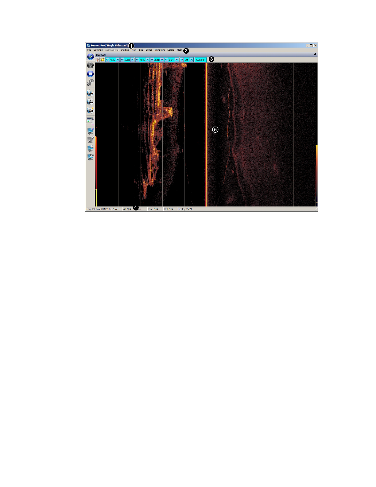
up as the sonar is moved forward through the water. A typical display is shown in
Figure 10.1, “Sidescan Sonar Data in Seanet Pro”
Seanet Pro SeaKing Sidecan Sonars
0374-SOM-00013, Issue: 01
27
© Tritech International Ltd.
Figure 10.1. Sidescan Sonar Data in Seanet Pro
The main areas of the display are:
1. Display Header - this part of the screen is used for system/software
identification.
2. Menu Bar - this is where system set-up functions can be accessed.
3. Settings Bar - this is where the Sidescan can be controlled and configured.
The settings bar is on top of every display window for each device that is connected
to the system. It includes a Tools Setup button, status indicator (pause/go) and
RAT dials and buttons
4. Status Bar - this part of the screen is used to display system status information,
logging status/progress and job specific information.
5. Sensor Display Area - this part of the screen is where the main Sidescan
data is displayed. Other pertinent data such as range scale, cursor and status
messages pertaining to the Sidescan may also be displayed within this area
10.2. Settings Bar
These controls are displayed on the Sonar Settings bar. Each button has a function
on the RAT as described:

Seanet Pro SeaKing Sidecan Sonars
0374-SOM-00013, Issue: 01
28
© Tritech International Ltd.
Note
On the RAT, F1 - F3 and F5 - F7 are not used.
Sonar Gain (C1, C4) This sets the sonar receive gain as required - typically
this is around 20% but can be varied according to
water and target conditions.
Contrast (C2, C5) This sets the display contrast between hard and soft
targets. It can help to find small features in a generally
featureless situation or exclude clutter from a heavily
featured seabed.
Range (C3) This sets the maximum range the sonar will scan.
Long ranges are scanned more slowly than short
ranges due to the limit imposed by the velocity of
sound in water (and may require a slower vehicle
speed if the the Sidescan is being towed).
Resolution (F4) Resolution toggles through 4 preset sampling periods
over the pulsed range.
Lo resolution produces the least samples and gives the
lowest resolution. The number of samples is increased
from Med, Hi through to Ult. Usually a Lo or
Med resolution are used for very fast tow speeds
where more scan-line updates are required giving
coarser detail. Hi or Ult should be used for detailed
examination of targets at a slower tow-speed.
Frequency On the sidescan sonars this is for information only and
cannot be changed.
Seanet Pro SeaKing Sidecan Sonars
0374-SOM-00013, Issue: 01
29
© Tritech International Ltd.
10.3. Application Tools
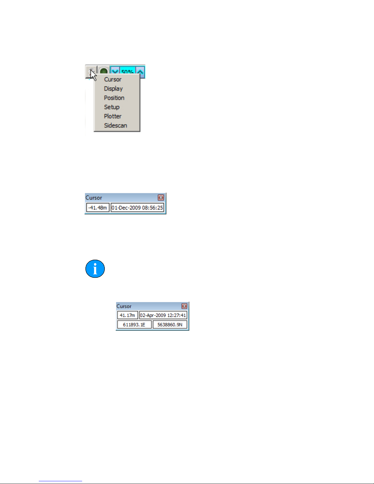
Cursor
Adds the cursor position panel to the sonar display, displays the Range and Time.
Move the mouse pointer over the Sidescan waterfall display to update the cursor
position giving Range to pointer and Time of scan-line that the pointer is positioned
over.
Note
If the system has real-time GPS position and heading data input, the panel
will extend to additionally display the target coordinates.
Display
Controls all the display options.
Seanet Pro SeaKing Sidecan Sonars
0374-SOM-00013, Issue: 01
30
© Tritech International Ltd.
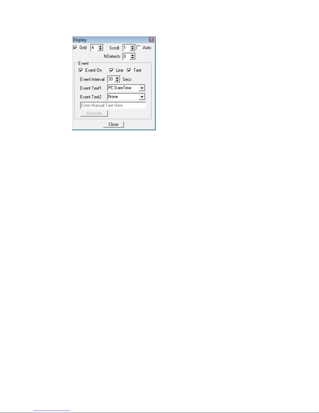
Grid Display the set number of range lines.
Scroll Zoom the waterfall plot on the time axis (i.e., accommodates different
vehicle speeds). Auto auto-adjust scroll from incoming vehicle speed
data.
NDetects Number of detects.
Event
On
Toggle display event on/off.
Line Toggle event line on/off.
Text Toggle event text on/off.
Event
Interval
Set a time interval of 1-60s between events. This is not applicable to
"Manual Text" events.
Event
Text
Text1 is displayed on the left and Text2 is displayed on the right.
Choose from:
• None (no event text displayed)
• PC DateTime (current date and time from the control computer)
• Manual Text (enter text via the text box and click the Annotate
button)
• Remote Text (from a serial "Aux" device configured through the
Utilities menu and Aux Device)
• GPS E/N (Easting/Northing from a GPS)
• GPS Lat/Lon (Latitude/Longitude from a GPS)
• GPS UTC Time
Seanet Pro SeaKing Sidecan Sonars
0374-SOM-00013, Issue: 01
31
© Tritech International Ltd.
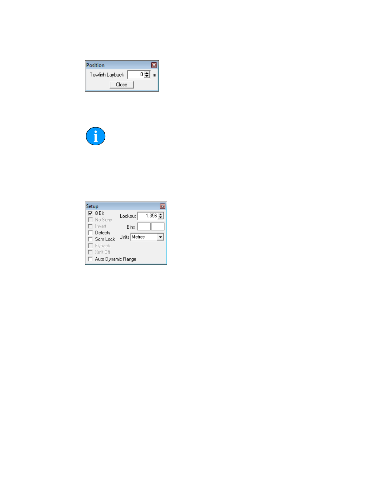
Position
Sets the lay-back offset (in metres) which is the distance between the Sidescan sonar
and reference datum (i.e., GPS receiver).
Note
This is only applicable to towed Sidescan sonars, the Towfish and SK150.
Setup
Sets various options to control the display of the Sidescan data.
8 bit Usually checked. Selects the intensity sampling of sonar data, if un-
checked the intensity will be set at 4 bit.
Detects Paint the leading edge of strong targets on the screen, used to
emphasise sub-bottom layers.
Scrn Lock Locks the number of range "bins" sampled to the screen resolution.
This over-rides the Resolution (F4) control.
Lockout Sets a minimum lockout range for the detects (always in metres).
Units Waterfall display range units (metres, feet, fathoms or yards).
Auto
Dynamic
Range
This will auto adjust the display contrast and sensitivity whilst the
Sidescan is running. Auto adjustment occurs periodically.
Plotter
This is for printout to a parallel port EPC or Alden thermal plotter.

Seanet Pro SeaKing Sidecan Sonars
0374-SOM-00013, Issue: 01
32
© Tritech International Ltd.
EPC/
Alden
Select the desired printer and then tick the Enabled tick-box to open
the parallel port connection.
Alden
Setup
When Alden is selected this button will become active. Click this
button to setup the Alden interface.
Negative inverts greyscale output. Output allows the left, right or
both channels to be chosen as the output. Line Repeat stretches the
printout by repeating line printouts (0 = off).
Sidescan
This is where the Sidescan channel settings are configured.
Interleaved Scan This button becomes enabled when a DST Sidescan is
connected. The DST Sidescan has capability to fire both
channels at the same time (as opposed to in "ping-pong"
mode) and this control enables simultaneous firing.
Slope Applies a Time Variable Gain adjustment to the received
signal returns to account for through-water attenuation of
the transmit pulse.

Seanet Pro SeaKing Sidecan Sonars
0374-SOM-00013, Issue: 01
33
© Tritech International Ltd.
Note
When the Interleaved Scan mode is enabled, the DST Sidescan
reverts to "ping-ping" operation as opposed to "ping-pong". This doubles
the quantity of data being transmitted to the surface with a larger overhead
on the Sidescan plotting function. To run in this mode a modern computer
(at least a Pentium 4) is required to cop with the increase in data. If the
CPU activity reaches 100% it will be necessary to disable Interleaved
Scan.
10.4. Dynamic Range and Sonar Rx Indicator
The dynamic range bar is the A/D sample window (with 64-colour mapping)
for the Sonar receive signal (which extends from 0 to 80dB).
To the right of the dynamic range bar is the Sonar receive signal strength
indicator (Yellow = Average amplitude over scan-line, Red = Maximum
amplitude echo for scan-line).
Normally the sampling window should not need to be adjusted from its default
position (as shown on the left). However, if used properly, adjusting the sample
window can produce better quality imaging.
The dynamic range bar can be adjusted to change Sonar display contrast and
sensitivity. Adjustment is made using the left and right mouse buttons.
Contrast adjustment Right-click on the bar and whilst holding
down the right button, move the mouse up/
down to increase/decrease the size of the
bar. The sampling window can be any size
between a range of 9 - 25dB. Decrease the
size of the sampling window to increase
the sonar display contrast. Ideally the
control should be set somewhere in the
centre of the allowed range (16 - 18
dB) to give the best results under most
conditions. Select a high value to reduce
the contrast of the sonar display.
Sensitivity adjustment Left-click on the bar and whilst holding
down the left button, move the mouse up/
down to decrease/increase the Sensitivity
of the Sonar receiver. Decreasing the
Sensitivity will produce a more saturated
display with greater weak-return content.
Increasing the Sensitivity will omit

Seanet Pro SeaKing Sidecan Sonars
0374-SOM-00013, Issue: 01
34
© Tritech International Ltd.
background noise and low level returns
seen at the receiver
The sonar receiver will accept a return signal in the region of 0 - 80dB. The dynamic
range controls are used to adjust the position of a sampling window within the 0-80dB
dynamic range band of the receive signal. An idealised representation of the sample
window is shown:

SeaKing Sidecan Sonars
0374-SOM-00013, Issue: 01
35
© Tritech International Ltd.
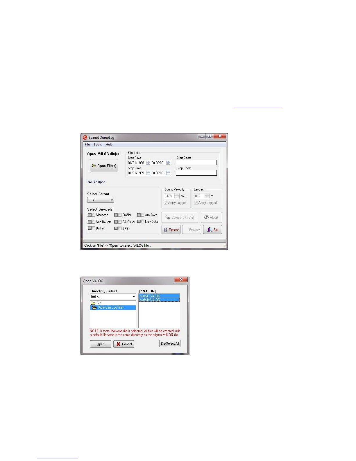
11. Seanet Dumplog
Note
The latest version of Seanet Dumplog is available from
www.tritech.co.uk. This section applies to version 2.20 of the software.
11.1. Overview of Process
Seanet Dumplog is a tool for converting Tritech International Ltd standard Seanet
log files with the filename extension of .v4log into other industry standard formats.
The process of conversion is as follows:
1. Acquire a log file from Seanet Pro.
2. Launch Seanet Dumplog and load the previously recorded log file.
3. Select the sonar type that has been used (in this case Sidescan) and if any GPS
data is present.
4. Select the desired output image format (e.g., TIFF or GeoTIFF).
5. Click on the Options button and configure any specific options for the output,
such as the colour to use.
6. Click on the Convert File(s) button and the process will start. After the
conversion a prompt will appear to name and choose the location of the save file.
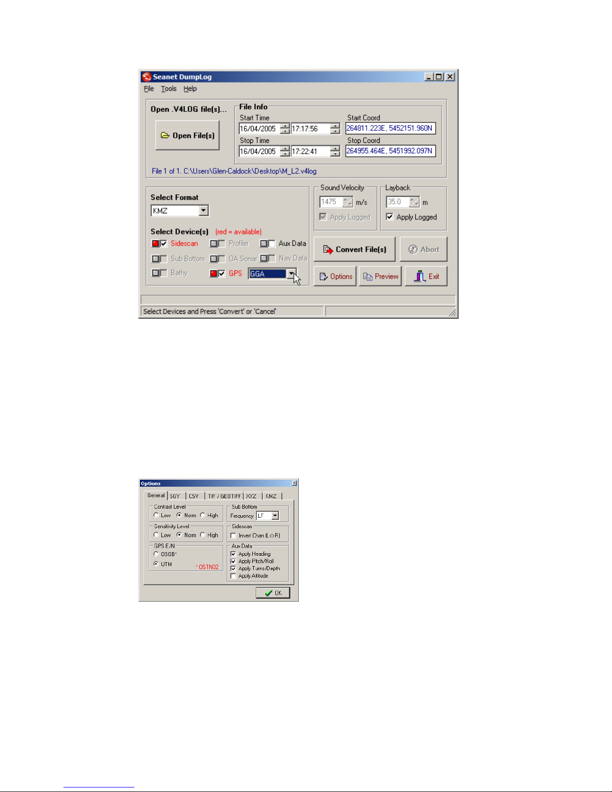
11.2. Application Window
The Seanet Dumplog utility is a simple application and most of the functions are
available on a single screen as shown below.
Seanet Dumplog SeaKing Sidecan Sonars
0374-SOM-00013, Issue: 01
36
© Tritech International Ltd.
11.3. Options Dialog
For advanced configuration and control of the output it is sometimes necessary to use
the Options dialog. This is split into six tabs with each tab relating to the different
output formats available.
General
The option relevent to the sidescan sonar on
this tab is Invert Chan (L<>R). This
will swap the Port and Starboard channels
over to create a mirror image if desired.
The Sensitivity Level can also be
altered to compensate for a very noisy sonar
scan which contains many returns.

Seanet Dumplog SeaKing Sidecan Sonars
0374-SOM-00013, Issue: 01
37
© Tritech International Ltd.
SGY
This tab is not relevant to Sidescan data.
CSV
The GPS Format drop-down list can be
used to configure GPS data (if it is present in
the log file). In the list Raw Data outputs
the GPS data as it was recorded and UTC,
E, N outputs in UTC format with Easting
and Northing position.
TIF/GEOTIFF
These are the options for configuring the
output of the Sidescan as images.
The selections made here will also determine
how the KMZ output is formatted as well.
XYZ
This tab is not relevant to Sidescan data.
Seanet Dumplog SeaKing Sidecan Sonars
0374-SOM-00013, Issue: 01
38
© Tritech International Ltd.
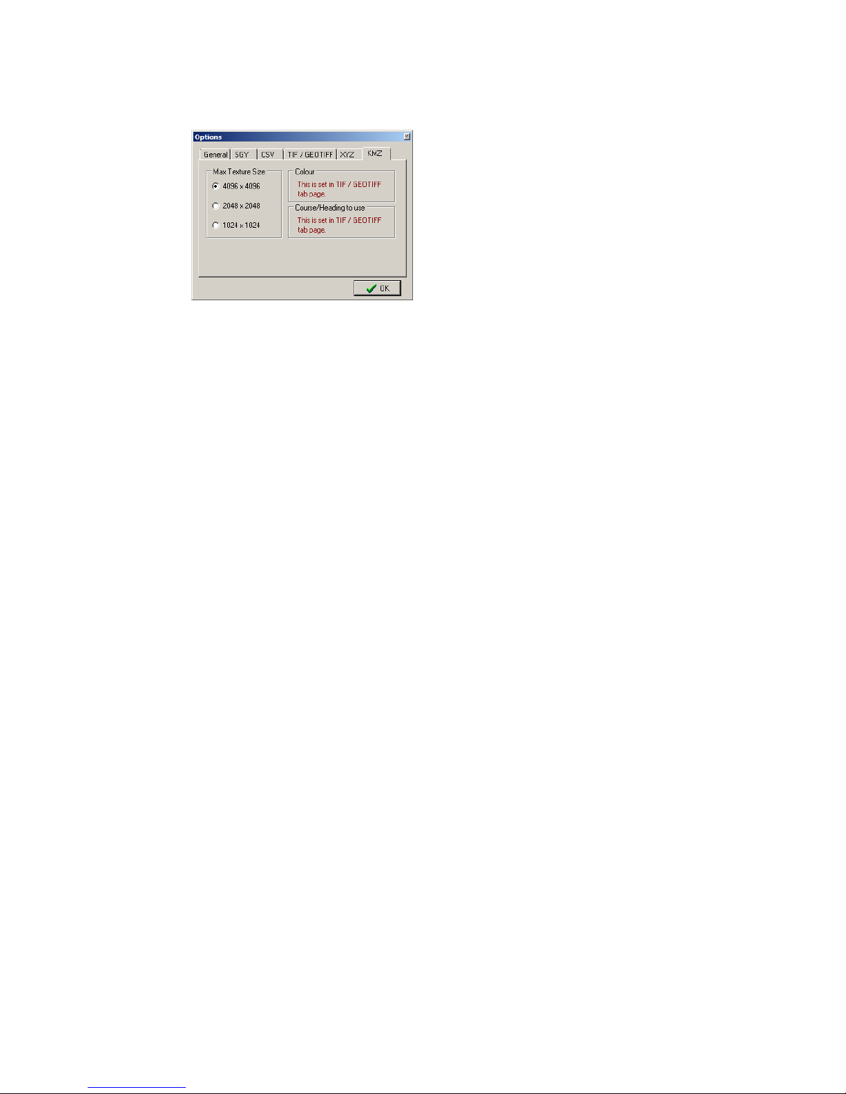
KMZ
For output to Google Earth KMZ format use
the TIFF/GEOTIFF tab to control the image
background colour and palette.
Use this tab to choose the image resolution.

SeaKing Sidecan Sonars
0374-SOM-00013, Issue: 01
39
© Tritech International Ltd.
Part IV
Image Tiler Software

SeaKing Sidecan Sonars
0374-SOM-00013, Issue: 01
40
© Tritech International Ltd.
12. Introduction
The Tritech Sonar Image Tiler is designed to allow sonar images to be stitched
together into a single larger image or mosaic. This allows mapping or surveying work
to build up a complete picture of the seafloor in important areas such as harbour floors,
wreck sites or around underwater structures such as bridge and platform supports.
Note
This manual applies to software version 1.3
Hardware & Software Requirements
•
A laptop, PC or SCU running Seanet Pro OR a computer running the offline
DumpLog utility and a previously recorded Sidescan log file.
• Positional data either from an external GPS/USBL linked into Seanet Pro or from
a manually entered World Position for the sonar installation.

SeaKing Sidecan Sonars
0374-SOM-00013, Issue: 01
41
© Tritech International Ltd.
13. Installation
The installer file for the Sonar Image Tiler can be found on the Hammerhead
Installation CD or downloaded from: www.tritech.co.uk
The installation CD will autorun on disc insertion, select the following button to
install the software:
If installing from the Internet an executable file called ImageTilerSetup.exe
will be downloaded. Run this file and follow the on-screen instructions.
Upon installation a program icon will be created on the Windows desktop and a
Tritech Image Tiler folder will be added to the Windows Start menu.
SeaKing Sidecan Sonars
0374-SOM-00013, Issue: 01
42
© Tritech International Ltd.
14. SeaKing Sidescan Image Capture
The Sidescan and GPS data first has to be recorded into a log file (.v4log) using
Seanet Pro. This log file is then opened in the DumpLog offline utility program
and a GeoTiff output is created. This GeoTiff output will also contain a World File
assuming that there is valid GPS data within the log file.
For the latest version of the DumpLog utility please visit: www.tritech.co.uk
Run DumpLog and click on Open File(s)
Select the log file or files that are to be converted.
Select the GEOTIFF output format and then tick the Sidescan and GPS device
boxes as shown below:

SeaKing Sidescan Image Capture SeaKing Sidecan Sonars
0374-SOM-00013, Issue: 01
43
© Tritech International Ltd.
Note
If the indicators next to the Sidescan or GPS boxes are not illuminated
red after opening the log file it indicates that there is no matching data. If
this is the case it will not be possible to create a GeoTiff and World File
output for use with the Image Tiler.
There are several TIF and GeoTiff settings that can be altered by clicking on
Options and selecting the TIF/GEOTIFF tab page.
The main settings are for a Colour Scheme to be applied to the output sidescan
imagery and a choice of methods to apply heading/course correction to the output
file. The Beam Width sets the width of each scan line which can help with gaps
that may occur, particularly when cornering.
Once setup is complete click on Convert File(s) to create the output. This
will create .TIF (GeoTiff image) and .TFW (World File) files which can then be
imported into the Sonar Image Tiler.

SeaKing Sidecan Sonars
0374-SOM-00013, Issue: 01
44
© Tritech International Ltd.
15. Software Functions
15.1. Toolbar
Import chart
Export as image
Save project
Load project
Clear project
Add tile
Delete all tiles
Reset all tiles
Resize tile
Create mosaic
Save mosaic
Zoom in
Fit to screen
Zoom out
Toggle coordinates dialog
Toggle coordinate system dialog
Toggle tile list dialog
Toggle chart
Show markers
Move marker
Pan tool
Erase tool
Area erase tool
Remove tile background
Export area
15.1.1. Project Controls
Import/Create Chart
For creating a blank chart or importing a previously created chart. For more
information on this function please see Section 16.2, “Create the Background Chart”.

Software Functions SeaKing Sidecan Sonars
0374-SOM-00013, Issue: 01
45
© Tritech International Ltd.
Export As Image
If an area is selected this button will export the selected area. If no area is selected
the whole chart will be exported.
For details of the supported file format please refer to: Section 17.2, “Saving Images
or Mosaics”.
Note
The markers will be embedded into the image file and if the image is
loaded again it will no longer be able to modify or hide them. If exporting
the image to use again as a chart the markers should first be hidden (see
Section 15.7, “Using Markers”).
Save Project
The first time this is pressed it opens a dialog to name and then save the current state
of the chart, tiles and markers as an XML file. Using this option allows the project to
be loaded later and the markers or tiles moved or hidden.
Subsequent presses of the button will not prompt for a filename and instead save over
the existing project - to save under a different name navigate to the File menu and
select Save Project As....
Note
If the tiles have been moved or rotated away from their original positions
it will no longer be possible to restore them after the Project has been
saved, i.e., the new "original" position which they will be returned to when
they are "reset" will be the position which they were in when the Save
Project button was pressed.
Load Project
For loading a previously saved Project file. The files are only generated by the Sonar
Image Tiler and are in XML format.
For details of the supported file format please refer to: Section 17.3, “Project Files”.
Clear Project

Software Functions SeaKing Sidecan Sonars
0374-SOM-00013, Issue: 01
46
© Tritech International Ltd.
Removes any loaded data and clears the workspace. Any unsaved data will be lost.
15.1.2. Tile Controls
Add Tile
Opens a dialog to load an image tile. Image tiles must be in the correct format and
have an associated world file.
For details of the supported file format please refer to: Section 17.1, “For Loading
Tiles”.
Delete All Tiles
Removes all the tiles from the chart. Any unsaved changes will be lost
Note
To delete a tile individually use the Tile List as detailed in
Section 15.6, “Tile List Dialog”.
Reset All Tiles
Resets all the tiles using the position, orientation and size from when they were first
loaded.
If the tiles were loaded as part of a project then they will be reset to the original state
that they were when the project was saved.
Note
To reset a tile individually use the Tile List as detailed in Section 15.6,
“Tile List Dialog”.
Resize Tile
Tiles can be resized individually using this tool. When the tool is enabled each tile
will show a thin red outline with anchors at the corners and side midpoints. The
Software Functions SeaKing Sidecan Sonars
0374-SOM-00013, Issue: 01
47
© Tritech International Ltd.
mouse pointer will change to arrows indicating the available resize direction when
it is positioned above the resize points. Click, hold and drag to resize the tile. The
corner anchors maintain aspect ratio while it is resized whereas the side anchors allow
the image to be stretched.
Create Mosaic
This will stitch all the visible tiles together into a single image. If only some of the
tiles are to be included the remaining ones should be hidden from view using the
Tile List as detailed in Section 15.6, “Tile List Dialog”.
Save Mosaic
Saves the newly created mosaic as an image with an accompanying world file which
can then be loaded as a tile for future Projects.
Using the Save Mosaic function has the advantage over Create Mosaic in
that it does not alter the tiles within the project so they can still be modified if desired.
The newly created mosaic is in a completely separate file.
For details of the supported file format please refer to: Section 17.2, “Saving Images
or Mosaics”.
15.1.3. Zoom
The zoom controls allow the user to Zoom In on an area of the screen by using the
button or by scrolling the mouse wheel forward.
Similarly, zooming out can be accomplished using the Zoom Out button or
scrolling the mouse wheel backwards.
The view can be reset so as the chart fits into the window by pressing the Fit To
Screen button
15.1.4. View/Hide Controls
These controls are the same as those found in the View menu and allow the different
dialogs to be shown or hidden from the workspace.
The background chart can be hidden to allow better viewing of the individual tiles by
selecting the View/Hide Chart button:

Software Functions SeaKing Sidecan Sonars
0374-SOM-00013, Issue: 01
48
© Tritech International Ltd.
For more detail on the functionality of the dialogs refer to Section 15.5, “Information
Dialogs” and Section 15.6, “Tile List Dialog”.
15.1.5. Markers
Using these buttons the markers can be shown, hidden or moved. For a full description
of the use of markers see Section 15.7, “Using Markers”
15.1.6. Tile Manipulation
Pan Tool
The pan tool is the default operation and allows the current viewpoint to be moved
around by clicking and holding the left mouse button - useful if zoomed in or using
a very large chart.
When this tool is selected and the mouse pointer is hovered over the tile handles the
functionality will change to that of move a single tile or rotate the tile (depending on
where the mouse pointer is located).
Note
This tool does not alter the position of the chart - it simply changes the
visible portion on the screen.
Erase Tool
Note
This action cannot be undone. To restore the original tile the tile has to be
deleted and then added afresh.
This tool allows parts of the sonar tile to be removed manually as if using an eraser.
To remove a section of sonar tile select this tool then click and drag the left mouse
button over the desired area. When this tool is active the mouse cursor should change
to an eraser.
If multiple tiles are overlapping the erase tool will work on the uppermost tile only
but if a portion is already erased the eraser will start to erase the tile below as well.
To avoid accidentially erasing the wrong tile, it is recommended that the tiles that are
not being worked on are disabled or hidden using the Tile List (see Section 15.6,
“Tile List Dialog”).
Software Functions SeaKing Sidecan Sonars
0374-SOM-00013, Issue: 01
49
© Tritech International Ltd.
Area Erase Tool
Note
This action cannot be undone. To restore the original tile the tile has to be
deleted and then added afresh.
This tool erases polygonal-shaped sections from the sonar image tile. To use it select
the tool then click (and release) on the sonar tile, move the mouse and click again to
add another point (the points will be joined by a red line). Keep adding points until
the desired shape has been constructed and then double-click to close the area (i.e.,
the last added point will be joined to the first point with a straight line). When the
area is closed the polygon that is created will be automatically deleted from the tile
and the red outline will also disappear. While this tool is active the mouse cursor will
change to a cross-hair with polygon shape.
All visible tiles that intersect with the defined polygon will have a section deleted. To
make sure that some tiles are preserved, first hide them from view - see Section 15.6,
“Tile List Dialog”.
Crop Background
Note
This action cannot be undone. To reset the tile, it must be deleted and
added again as if it is new.
To control the amount of sonar data displayed in a tile the automatic background
removal tool uses an intelligent algorithm to determine unwanted sections and remove
them from the tile. Unwanted background pieces are those that are typically around
the edge of the sonar scan and do not add any detail to the images. In general, acoustic
shadows around areas of high intensity should be kept as they add detail and context
to the image.
15.1.7. Image Export Area
The Image Export Area selection tool enables restricted areas of the workspace to
be exported to an image file. The mouse pointer will change to a cross-hair for more
accurate selection. To use, simply draw a box around the area to be exported and then
press the Export As Image button ( )

Software Functions SeaKing Sidecan Sonars
0374-SOM-00013, Issue: 01
50
© Tritech International Ltd.
Note
Only when this button is enabled will the selection be used as the export
area, otherwise the entire chart will be used.
15.2. Moving tiles
The Pan Tool button has to be selected for this function to work.
When the mouse pointer is over the centre of the tile it will change to a hand icon.
Hold down the mouse button to drag the tile and position it correctly.
15.3. Rotating tiles
The Pan Tool button has to be selected for this function to work.
A tile can be rotated by selecting and moving the rotation lever (see Figure
Figure 15.1, “Rotating the Tile”). The mouse pointer will change to show a hand with
rotation arrows when it is positioned above the end of the lever. Holding the mouse
button down and dragging in a circular motion will rotate the tile:
Figure 15.1. Rotating the Tile
The amount of rotation will be displayed in the Tile List panel (which can be
displayed using the View menu and selecting Tile List).

Software Functions SeaKing Sidecan Sonars
0374-SOM-00013, Issue: 01
51
© Tritech International Ltd.
The colour of the rotate handle can be changed by navigating to the Tools menu
and selecting Options
15.4. Mosaic of Tiles
To create a mosaic of tiles it will be necessary to have multiple tiles together within
a single geographic region. It will not be possible to create a mosaic if the tiles are
very far apart, likely as a result of having an incorrect or corrupt world file which
results in their incorrect placement.
Creating a mosaic is a simple process, first arrange the tiles as desired and hide tiles
that are not going to be included in the final mosaic, then press the mosaic button
on the toolbar ( ) which will start the mosaicking process. An example of this is
presented in Figure 15.2, “Mosaicking Tiles”.
Note
The mosaicking process is irreversible and will result in a new tile created
which cannot be split into the original tiles. To restore the original tiles
they will have to be re-loaded.
Figure 15.2. Mosaicking Tiles

Software Functions SeaKing Sidecan Sonars
0374-SOM-00013, Issue: 01
52
© Tritech International Ltd.
Note
If Save Mosaic is pressed instead the output will not be on the screen
but to a file so a file chooser dialog will present itself.
15.5. Information Dialogs
There are also three information panels accessible from the toolbar or the View menu:
the tile list; mouse position; and the coordinate system used. Both the tile list and the
mouse view display the position of tile centres or mouse pointer, respectively, using
the selected coordinate system.
Coordinate System
The Coordinate System display can be viewed and controlled by selecting
the button or using the View menu and select Coordinate System option.
This allows the user to choose between using Decimal Degree, Degrees and
Decimal Minutes, Degrees, Minutes and Seconds and Universal
Transverse Mercator (UTM). Selecting one of these options automatically
updates the display in the both the Mouse Position and Tile List display
panels.
Mouse Coordinates
The Mouse Coordinates display is also controlled from the View menu and
View button collection . It shows the mouse position in the context of the chosen
coordinate system.
15.6. Tile List Dialog
The Tile List panel can be made visible using the View menu and selecting the
Tile List option.
Alternatively the Tile List can also be viewed using the button: .
Action on Multiple Tiles
By holding down the shift key on the keyboard it is possible to select
multiple tiles in the Tile List and move them up/down the layers
together, show/hide them as a group or delete/reset multiple tiles in one
go.

Software Functions SeaKing Sidecan Sonars
0374-SOM-00013, Issue: 01
53
© Tritech International Ltd.
Saving the tile will only work on one tile at a time.
Layering tiles
Layering the tiles determines the order in which they are displayed, i.e., tile 1 is
displayed in front of tile 2. The order can be changed by moving tiles up and down
in this list, either as individual tiles or in groups.
Note
If centre marks or rotation handles obscure one another interaction will
occur using the lowest numbered (corresponding to the topmost) tile so it
may be necessary to re-order the tiles to gain access to the handles.
Click on the row containing a tile to highlight it and then press either the UP or DOWN
arrow to bring the image forward or backward on the display by one layer.
Multiple tiles can be moved in one go by selecting each one and holding down the
control key on the keyboard (or by selecting a span using the shift key). Once
selected the tiles can be dragged as a group by holding down the mouse button and
moving up or down the list to re-order them.
The tiles will be automatically renumbered with the lowest number being the first
one displayed.
The tiles can also be controlled using a menu that is accessible by clicking on the tile
entry in the list with the right mouse button. Using this method the tile can also be
moved immediately to the front or the back of the display stack.
Save Selected Tile
Saving a tile will export it with a new world file so that any changes that have been
made to the position or orientation can be preserved.
Delete Selected Tiles
Deleting a tile will permanently remove it from the display. Any changes made to
it will be lost.
If multiple tiles are selected when this button is pressed they will all be deleted.

Software Functions SeaKing Sidecan Sonars
0374-SOM-00013, Issue: 01
54
© Tritech International Ltd.
Reset Selected Tiles
Resetting a tile changes the tile location, orientation and size to the coordinates and
rotation value contained in the world file that was originally used to load the tile. Any
subsequent movements or rotations that have been made are lost.
If multiple tiles are selected when this button is pressed they will all be reset.
Note
If a project has been loaded the tile will be reset to the orientation when the
project was loaded. The process of saving the chart and tiles as a project
removes the original tile data so the only way to restore the original tile
would be to delete it and reload it.
Show/Hide Selected Tiles
Tiles are hidden by de-selecting the check box to left of the tile number.
If multiple tiles are selected when this button is pressed they will all be shown/hidden.
15.7. Using Markers
The Image Tiler has the ability to import a marker file which has been saved from
Seanet Pro (marker files have the extension ".mrk") or from a CSV text file (full
details of the marker files are in Appendix D, Marker Files).
First create the marker file from the chart in the MicronNav application in Seanet
Pro. Then open the marker file by navigating to Import Marker File from the
Tools menu.
The imported markers will be overlayed on top of the chart:

Software Functions SeaKing Sidecan Sonars
0374-SOM-00013, Issue: 01
55
© Tritech International Ltd.
The positions of the markers is shown next to the location. Markers can be hidden
using the button on the toolbar: .
To move a marker first select the move marker button ( ) and then click on the
marker and drag it to the new location.
Note
If markers are displayed and Export as Image is selected they will
be merged with the background. If the chart is to be used again it will
not be possible to move or remove the markers. For this functionality
the chart should be saved without the markers or with them hidden. If
Save Project is selected the chart, tiles and markers are all saved as
individual entities and can be interacted with as normal.

SeaKing Sidecan Sonars
0374-SOM-00013, Issue: 01
56
© Tritech International Ltd.
16. Creating the Mosaic Image
Figure 16.1. Completed Mosaic
A mosaic as shown in Figure Figure 16.1, “Completed Mosaic” can be created with
the Sonar Image Tiler using a background chart, and sonar image tiles with their
associated world files. The user must first set a background to place the image tiles.
This background is called a "chart"; although if an actual survey chart is not available
a blank canvas can be used. There is also the option to use the first added tile
as a reference. All image tiles and background chart or blank canvas require georeferencing. This is done during the creation of the chart by entering Position
Co-ordinates for the top-left corner and a chart Width and Height.
With a background chart in place the sonar image tiles can then be loaded and any
position or rotation corrections made. The entire chart and tiles, or a selected area,
can be exported as an image file and a (separate) world file.
This chapter is organised into sections explaining the process of creating a mosaic,
the tools available to the user, and also exporting an image or saving the project.
Note
Load Project allows a previously created chart, collection of tiles
and markers to be loaded for further editing or for selecting an area to be
exported as a bitmap.
16.1. Overview of Process
Prior to starting the mosaic process it is necessary to obtain the following:

Creating the Mosaic Image SeaKing Sidecan Sonars
0374-SOM-00013, Issue: 01
57
© Tritech International Ltd.
• An image with GPS data in an associated world file to use as a background. Or
appropriate GPS coordinates and geographical dimensions sufficient to encompass
all of the sonar image tiles if creating the chart manually.
• A set of sonar image tiles from a Seanet Pro session which include GPS data in
accompanying world files.
Given data already created using Seanet Pro the process for tiling images into a
mosaic is as follows:
1. Create a chart: either from an image, import a previously created chart or create
a blank chart from GPS data.
2. Load sonar image tiles onto the chart.
3. Manipulate the image tiles to the correct position (if required).
4. Either export the resulting mosaic as a bitmap (with world data) or save as a project
(containing a chart and a collection of tiles) to work on again later.
16.2. Create the Background Chart
The Sonar Image Tiler starts with a blank screen:
First create a chart background onto which the sonar image tiles will be placed.
If Seanet Pro is running on the PC and has a chart configured as part of its Nav
application then you can select it using the Files menu and Open Seanet Chart
option. If no Seanet chart is available click on the Import/Create Chart button
to set up a new chart background.
Note
It is also possible to use the first tile as the chart background - see below
for the procedure for adding tiles. This tile cannot be moved or rotated
and acts as the fixed reference point for other tiles.
In the Add Chart dialog box there are three options for adding or creating a chart.
The user can select to use an image with associated world file; an image with manually
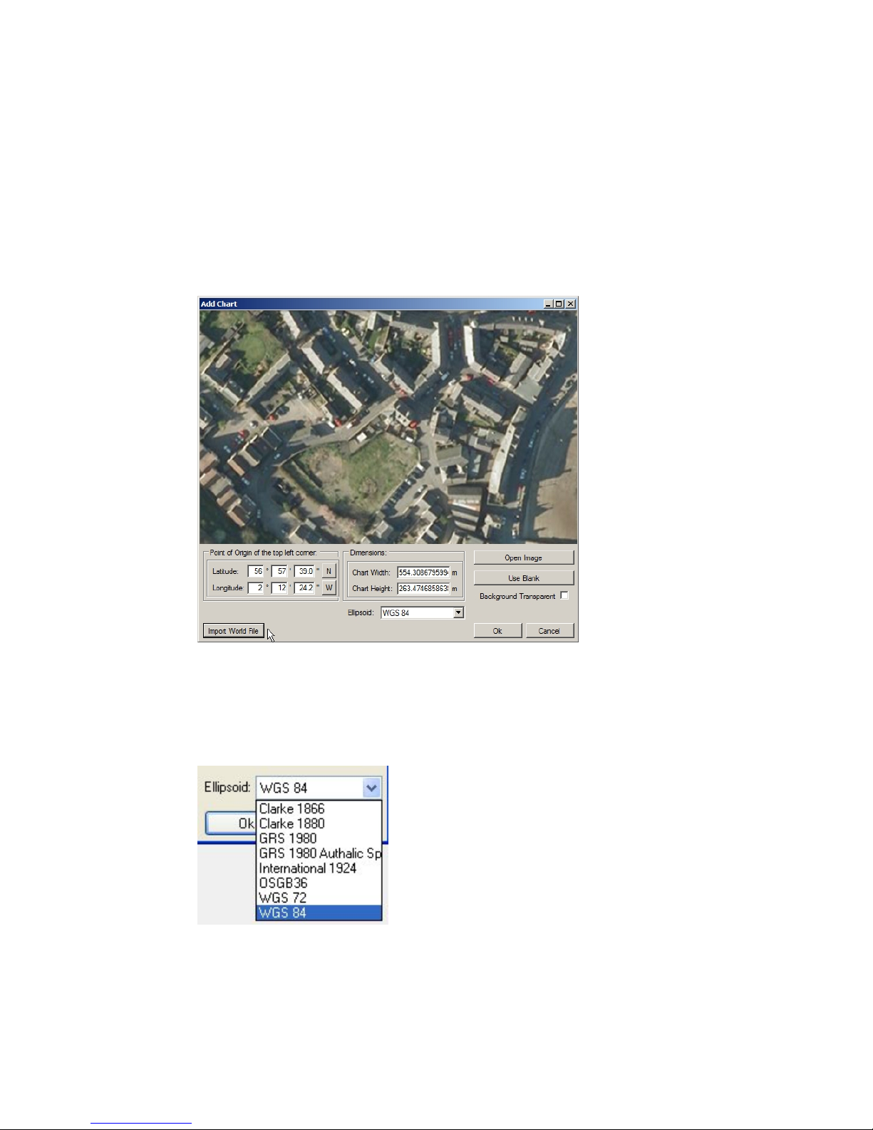
Creating the Mosaic Image SeaKing Sidecan Sonars
0374-SOM-00013, Issue: 01
58
© Tritech International Ltd.
entered position and scale; or a blank chart with manually entered position data. These
options are explained further in the following sections.
16.2.1. Image with World File
Select Import World File for the Open World File dialog and select the
appropriate world file. The format of the world file can be either .bpw (bitmap), .jgw
(jpeg), .tfw (tiff) or .wld (generic/CAD).
The world file format for x and y co-ordinates can either be in Eastings/Northings (E/
N) or Longitude/Latitude (L/L). If co-ordinates are in E/N then a Zone will need to
be entered and a reference Ellipsoid selected (for definition of latitude, longitude
and elevation).
Verify chart parameters are correct and click OK to confirm and load this chart onto
the display.

Creating the Mosaic Image SeaKing Sidecan Sonars
0374-SOM-00013, Issue: 01
59
© Tritech International Ltd.
16.2.2. Image with Manual Positional Data
First, select Open Image button to bring up the Open Chart dialog and select
the required chart image. The image format can either be .bmp (bitmap), .jpg (jpeg)
or .tif (tiff).
Note
Where an associated world file (matching name) is detected in the same
folder as the selected image the chart parameters will automatically be
loaded.

Creating the Mosaic Image SeaKing Sidecan Sonars
0374-SOM-00013, Issue: 01
60
© Tritech International Ltd.
Next, enter the Point of Origin co-ordinates and the chart Dimensions.
If the Universal Transverse Mercator (UTM) coordinate system is used a reference
Ellipsoid will also have to be selected at this point (the default is WGS84 (World
Geodetic System 1984)).
16.2.3. Blank Chart
Select Use Blank to create a blank image for the chart background. A default width
and height will be set.
The Point of Origin co-ordinates and the chart Dimensions will have to
be set. If UTM then also select a reference Ellipsoid at this point (the default is
WGS84).
16.2.4. Co-ordinate System
When creating charts the Point of Origin co-ordinates will be in the format
that is currently selected in the Coordinate System panel. To change this select
Cancel and navigate to the Coordinate System control (if this is not visible
go to the View menu and select Coordinate System).

Creating the Mosaic Image SeaKing Sidecan Sonars
0374-SOM-00013, Issue: 01
61
© Tritech International Ltd.
16.3. Add Image Tiles
Once the chart background has been loaded sonar image tiles can be added. Tiles
must be within the same geographic area of the chart background.
Either click on the Add Tile icon, or add the tile through the Tools menu
and Add Tile option.
• A dialog enabling searching and adding of images is shown. The images can
be in .bmp (bitmap), .jpg (jpeg) or .tif (tiff) formats. A matching world file is
required in the same folder or the image will not load.
• The tile will be added on top of the chart if the geographic co-ordinates are within
the background area.
• Simply repeat these steps to add further tiles.
Note
Several files can be added at the same time by holding down the Ctrl
key whilst selecting the images.
16.4. Manipulate Image Tiles
The position information for tiles is dependent on the settings when the tile scans
were created.
If the imported position is incorrect the tiles can be repositioned on the chart at any
point after they have been added to provide a more accurate mosaic. There are several
repositioning functions available: moving, rotating, and resizing. As well as tools to
alter the appearance of shadows in tiles: automatic cropping of unwanted shadows,
manual eraser, and area erase.
For full details of the possible ways to manipulate the tiles please refer to Chapter 15,
Software Functions
16.5. Save the Project
Save Project allows the chart to be saved as a chart and a collection of tiles (and
any markers) so it can be loaded for editing at a later date. The user is prompted for
a file name, with the file type being XML.
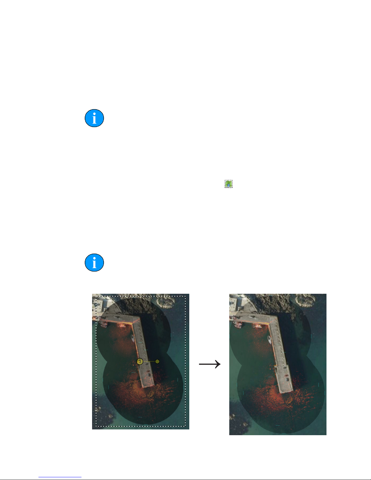
Creating the Mosaic Image SeaKing Sidecan Sonars
0374-SOM-00013, Issue: 01
62
© Tritech International Ltd.
16.6. Exporting the completed mosaic as an image
Charts can either be exported whole or areas can be selected and saved. To export
the entire image simply select Export as Image from the Files menu. This
will then display a dialog prompting for the desired location and name of the file.
This output image will have an associated world file so it can be imported into other
software packages with the geo-referencing intact.
Note
If there is an area selected on the chart, clicking Export as Image
will only save what is contained within the selection region. The format of
the saved chart will depend on the format of the input chart (i.e., a .bmp
input will generate a .bmp output).
To create an output image using the Selection Tool follow these steps:
First click on the Image Export Area button:
Using the left mouse button click and hold anywhere on the chart and then drag the
cursor across the screen to create a selection area.
Click on the Files menu and go to Export as Image. Enter a filename and
select the desired file type (.jpeg, .bmp or .tiff) then click Save. A world file will be
created with the same filename as the image file.
Note
There will also be a .kmz file created. This is a Google Earth file format
and will allow the image to be viewed in Google Earth.

Creating the Mosaic Image SeaKing Sidecan Sonars
0374-SOM-00013, Issue: 01
63
© Tritech International Ltd.
Selection area within dotted line Output image
Note
It is also possible to output just the tiles (i.e., without the background
chart) by clicking on the Save Mosaic button:

SeaKing Sidecan Sonars
0374-SOM-00013, Issue: 01
64
© Tritech International Ltd.
17. Supported File Formats
17.1. For Loading Tiles
In order to correctly position the images each image tile file should be accompanied
by an equivalent "world file" which contains positional data. This data should come
from a GPS linked into Seanet Pro. If a GPS is available Seanet Pro will automatically
create a world file with the correct data when a Snapshot is taken.
The following file formats are supported:
Image Type World File
.bmp .bpw
.jpeg/.jpg .jgw
.tiff/.tif .tfw
.png .pgw
Note
The image file and world file should have the same filename (i.e.,
sonar.bmp and sonar.bpw).
Note
The image tiles have to be saved from the latest version of Seanet Pro; if
an older version is used they will not open in the Sonar Image Tiler. If
in doubt, remove the current version of Seanet Pro and either download
the latest version from www.tritech.co.uk or re-install from the CD-ROM
which contained the Image Tiler installation program.
17.2. Saving Images or Mosaics
Saving an image can either be the whole chart (with any visible tiles or markers), a
marked out section or a mosaic of tiles either way the supported formats are:
.bmp Bitmap image
.kmz Google Earth format
.png Portable Network Graphic
Note
The Sonar Image Tiler will automatically create at matching world file
for the saved image.

Supported File Formats SeaKing Sidecan Sonars
0374-SOM-00013, Issue: 01
65
© Tritech International Ltd.
17.3. Project Files
The Sonar Image Tiler uses a customised XML format for saving and loading
projects. These project files will preserve any tile data or marker data so that they can
be manipulated again at a later stage or transferred to another computer for editing.
Note
Due to the fact that the project files contain the data for all the tiles, if the
project has many tiles it can result in the production of large XML files.
17.4. Marker Files
Two different marker file types are supported both of which are in CSV format but
with different filename extensions and different complexity:
.mrk Seanet Pro full length marker files.
.csv A shortened version of the Seanet Pro format.
Note
For full details of the marker file formats please see Appendix D, Marker
Files.

SeaKing Sidecan Sonars
0374-SOM-00013, Issue: 01
66
© Tritech International Ltd.
18. Example: Using Sidescan Image Tiles
Several .v4log files have been created in Seanet Pro that contain SeaKing Sidescan
and GPS NMEA data. Each file contains the sidescan data for one track from a
lawnmower style survey. GeoTiff files (and corresponding world files) were created
using the DumpLog utility and these file-sets were added/imported into the Image
Tiler application as sonar image tiles.
The files used for this example were as follows:
GeoTIFF file: Outfall3.TIF
World File: Outfall3.TFW
Outfall3.TIF image, ©Cawthron
Contents of
Outfall3.TFW:
0.0121457489878543
0
0
-0.121457489878543
299883.8970386512
4836012.20188229
Outfall4.TIF image ©Cawthron
Contents of
Outfall4.TFW:
0.0121457489878543
0
0
-0.121457489878543
300067.466645638
4835950.35472915
The TIF and TFW file sets were imported into the Sonar Image Tiler using the Add
Tile button. The first tile imported was used as the reference background image.
Further tiles were added and repositioned.

Example: Using Sidescan Image Tiles SeaKing Sidecan Sonars
0374-SOM-00013, Issue: 01
67
© Tritech International Ltd.
With the image tiles added an area was highlighted using the Selection Tool
and the area was saved to file using the Export Chart as Image button. The
saved image mosaic appears as follows:
Sidescan Images provided courtesy of Cawthron, New Zealand (image shows mega
ripples of sand off the coast of Foveaux Strait near Bluff)

SeaKing Sidecan Sonars
0374-SOM-00013, Issue: 01
68
© Tritech International Ltd.
Part V
Service and Maintenance

SeaKing Sidecan Sonars
0374-SOM-00013, Issue: 01
69
© Tritech International Ltd.
19. Maintenance
19.1. After each use of the equipment
Make sure that after using the sonar head that it is washed down with fresh water and
check the unit for any signs of obvious damage.
Once the unit is clean; dry thoroughly and place in the storage container.
Note
If the unit is fitted to an ROV it is advisable to remove from its fitting and
wash both with fresh water and dry both thoroughly prior to re-assembly.
This will prevent the build up of corrosive salts in any crevices between
the sonar and mounting bracket.
19.2. Regular maintenance
There are no user serviceable parts inside the sonar and it is not necessary to take it
apart for any maintenance tasks.
A regular inspection routine should be established to ensure that the sonar head,
particularly stress points such as the connectors, does not have any damage.
If the system is in regular use, or submerged routinely for extended periods, it is
advisable to arrange for an annual service to be carried out by Tritech International
Ltd. This service will enable the equipment to be checked thoroughly or for any worn
parts to be replaced and will enable long-term trouble free operation of the sonar. For
details of the servicing options available contact Tritech International Ltd.
19.3. Storage of Equipment
If storing the equipment for extended periods make sure that it is completely dry (if
necessary leave to air-dry before stowing).
Pack into storage containers along with several pouches of silica gel. The original
packing containers contain specific foam cut-outs for the storage of the equipment
so wherever possible they should be re-used. The foam will absorb moisture so if
the cases are allowed to get wet they should be dried thoroughly prior to stowing
equipment in them.
Any supplied cabling is jacketed with polyurethane which is resistant to corrosion but
if it is intended to store the reel for an extended period without use then it is advisable

Maintenance SeaKing Sidecan Sonars
0374-SOM-00013, Issue: 01
70
© Tritech International Ltd.
to un-reel the cable and dry its entire length. This will also give the opportunity to
inspect the cable for any damage which has occurred during use.
19.4. Software Maintenance
The operating system required on the computer is Microsoft Windows and should
have appropriate anti-virus or protection software installed.
If it becomes necessary to reload the system software it is advisable to download
the latest version of Seanet Pro from www.tritech.co.uk. If no Internet connection is
available the supplied CD-ROM (or USB) should be used to re-install the software.
Note
Prior to installing the software make sure that Windows and any required
drivers for the computer are fully installed and working.
To ensure that the system remains secure and error free it is recommended that no
extra software other than is absolutely necessary (such as anti-virus software) is
installed on the computer.
If the sonar has been supplied with a Tritech SCU then the operating system can be
re-initialised using the provided USB memory stick. Please refer to the SCU manual
for more details (document reference: 0581-SOM-00002).
Note
A regular backup schedule for any important log files should be in place
for the computer since re-initialisation may erase the hard drive contents.

SeaKing Sidecan Sonars
0374-SOM-00013, Issue: 01
71
© Tritech International Ltd.
20. Troubleshooting
Continuous status Timeout 10 message
No communication with the device
(In this case the Node number of the device is 10). Check the power and
communications links to the sonar head for continuity and for correct polarity, voltage
and ensure that the power supply can provide sufficient current to power all devices.
If internal damage is suspected, contact Tritech International Ltd for service and
repair options.
No seabed sonar targets observed
Sonar at incorrect height above seabed.
Ensure that the head is positioned sufficiently close to the seabed.

SeaKing Sidecan Sonars
0374-SOM-00013, Issue: 01
72
© Tritech International Ltd.
Appendix A. ARCNET Termination
The ARCNET communication link requires a termination resistor to be installed at
each end of the umbilical cable. Normally this is supplied fitted within the ARCNET
cable DA-15 connector at the surface and is left for the user to fit at the sub-sea end
in a convenient junction box or by use of the yellow waterblock.
Caution
Fitting the resistor inside the unit is not recommended and may invalidate
the warranty.
The purpose of these terminations is to attenuate any electrical interference or
"reflections" which may occur due to an impedance mis-match and the overall aim
is to improve signal quality and negate any effects which might otherwise be felt by
other sources of impedance such as from the cable itself.
The diagram below shows best practice to use when installing termination resistors
on an ARCNET network of Tritech International Ltd sonar products.
Note
A special yellow waterblock is available from Tritech International Ltd
which contains an in-line impedance of 39ohm which will enable quick
and easy installation of the subsea termination resistor.
Cable length Termination Baud rate setting
Less than 100m Single 39ohm subsea resistor Normal baud rate
100-1200m 270ohm at surface and 39ohm subsea Normal baud rate
1200-2500m 270ohm at surface and 39ohm subsea Half baud rate
Note
If there is more than one sensor connected then the sub-sea resistor should
be fitted at the junction box or splice of the cable.

SeaKing Sidecan Sonars
0374-SOM-00013, Issue: 01
73
© Tritech International Ltd.
Appendix B. CHIRP Signal Processing
There are several advantages of Tritech International Ltd Digital Sonar Technology
(DST) which allows the use of CHIRP signal processing technology in order to
improve the images generated by the sonar.
In monotonic (single frequency burst) sonar, the range resolution is determined by
the length of the transmitted pulse. The smaller the pulse is, the greater the resolution
achievable and vice-versa. The smallest pulse length is typically 50 micro seconds
and velocity of sound in water is approximately 1500 metres/second which gives a
range resolution of 37.5mm. This result effectively determines the ability to resolve
separate targets.
Target
Seperation
T1
T2
Time
Transmitted Pulse
Target 1 echo
Target 2 echo
Sonar range
resolution
Target
seperation
Combined echo
(seen by the receiver)
Using the example above, if two targets are less than 37.5mm apart then they cannot
be distinguished from each other. The net effect is that the system will display a single
large target, rather than multiple smaller targets.
CHIRP signal processing overcomes these limitations by sweeping the frequency
within the burst over a broad range of frequencies throughout the duration of
transmission pulse. This creates a signature acoustic pulse - the sonar knows what
was transmitted and when. Using pattern-matching technology, it can now look for
its own unique signature being echoed back from targets.
Transmitted signal
Transmitter
circuit
Receiver
circuit
Received decoded signal
pulse duration
In a CHIRP system, the critical factor determining range resolution is now the
bandwidth of the CHIRP pulse which means the range resolution is given by:
Range resolution =
velocity of sound
2 x bandwidth
The bandwidth of a typical Tritech International Ltd CHIRP system is 50kHz
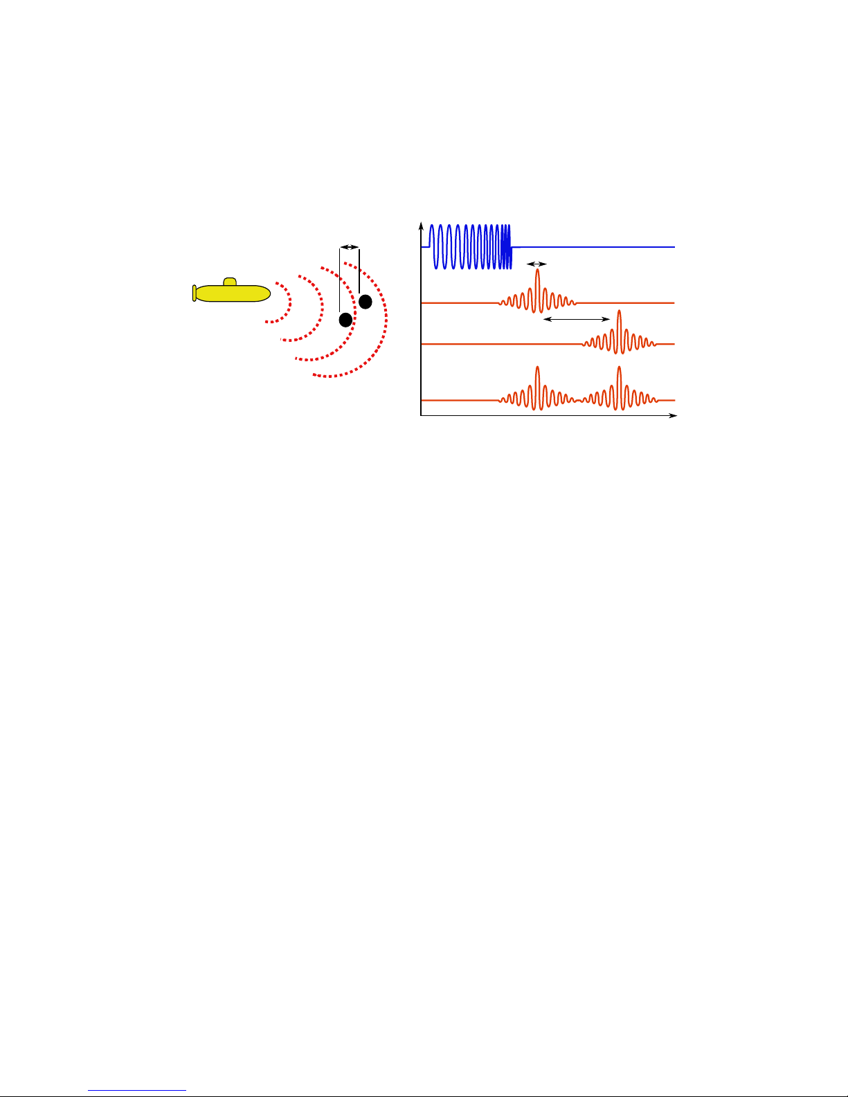
CHIRP Signal Processing SeaKing Sidecan Sonars
0374-SOM-00013, Issue: 01
74
© Tritech International Ltd.
With velocity of sound in water of 1500m/s this gives a new range resolution of
15mm.
This time, when two acoustic echoes overlap, the signature CHIRP pulses do not
merge into a single return. The frequency at each point of the pulse is different, and
the sonar is able to resolve the two targets independently.
Target
Seperation
T1
T2
Time
Transmitted Pulse
Target 1 echo
Target 2 echo
Sonar range
resolution
Target
seperation
Combined echo
Both targets
are visible.
The response from the pattern-matching algorithms in the sonar means that the length
of the acoustic pulse no longer affects the amplitude of the echo on the sonar display.
Longer transmissions (and operating ranges) can be achieved without a loss in range
resolution.
Additionally CHIRP offers improvements in background noise rejection, as the sonar
is only looking for a swept frequency echo, and removes random noise or out-ofband noise.

SeaKing Sidecan Sonars
0374-SOM-00013, Issue: 01
75
© Tritech International Ltd.
Appendix C. Networking COMv6 Devices
Overview
Some of the newer SeaKing ROV Sidescan and SK150 devices may be fitted with
the COMv6 Communication PCB and have the AutoComms feature. This is meant to
enable automatic connection of a single sonar device to a computer without the need
to manually select communication protocols.
The sonar scans available communication settings until it finds an active one (the
one which is connected to the computer). Once an active one has been found it will
set its communication protocols to the correct settings to enable communication with
the PC.
The AutoComms feature does not work for networked devices though and instead the
following procedure should be adopted to allow communication between the sonar
heads and surface PC.
The basic procedure is:
1. Set the communication protocols of the surface unit to match the sonar (i.e., if the
sonar is communicating on RS232, set the surface unit to RS232)
2. Turn off AutoComms (if present)
3. Change the sonar settings to meet new requirements of the system - at which point
it will "disappear" from the computer
4. Repeat for all the sonar devices to be connected
5. Change the surface unit to match the new system settings
Manually Setting Comms
Note
Unless it has been specified differently at time of purchase the factory
default settings of all Tritech International Ltd sonars are RS232 serial at
115.2kBd so if AutoComms has previously been disabled these settings
could be tried first.
1.
Set Surface Unit to Match Sonar
Launch the Seanet Setup application and then select the Setup option from the
Action column.

Networking COMv6 Devices SeaKing Sidecan Sonars
0374-SOM-00013, Issue: 01
76
© Tritech International Ltd.
A warning should appear to show that the settings are going to be changed,
acknowledge this and then select the appropriate setting from the dialog box which
presents itself. The example below shows the setting for port C of a SeaHub being
changed to RS232 from RS485.
2.
Set Sonar to New Setting
The sonar and SeaHub should both show a Status of OK and have green status
colour. Once they are both in this condition select the Setup action for the sonar
but this time click on the sonar which will then bring up the Digital Sonar
Setup screen:
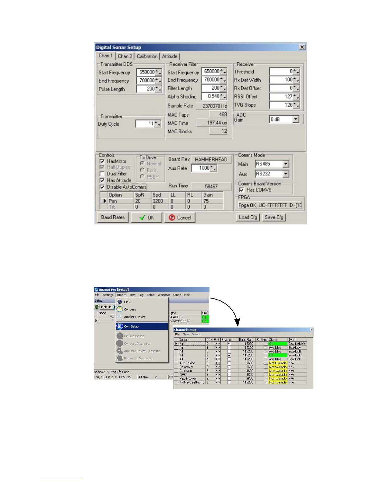
Networking COMv6 Devices SeaKing Sidecan Sonars
0374-SOM-00013, Issue: 01
77
© Tritech International Ltd.
First make sure that the Disable AutoComms option is checked and then
change the Comms Mode settings in the bottom right corner. If working on
an ARCNET network the baud rates should be changed by clicking on Baud
Rates (in the bottom left of the above screenshot). Serial baud rates are set
up using the Channel Setup screen which is accessed by returning to the
main setup screen and navigating to Com Setup from the Utilities menu:
3.
Repeat the above procedures for all sonar devices which are going to be on the
network.
4.
Set the surface control box to match the new communication protocols of the
networked sonars.
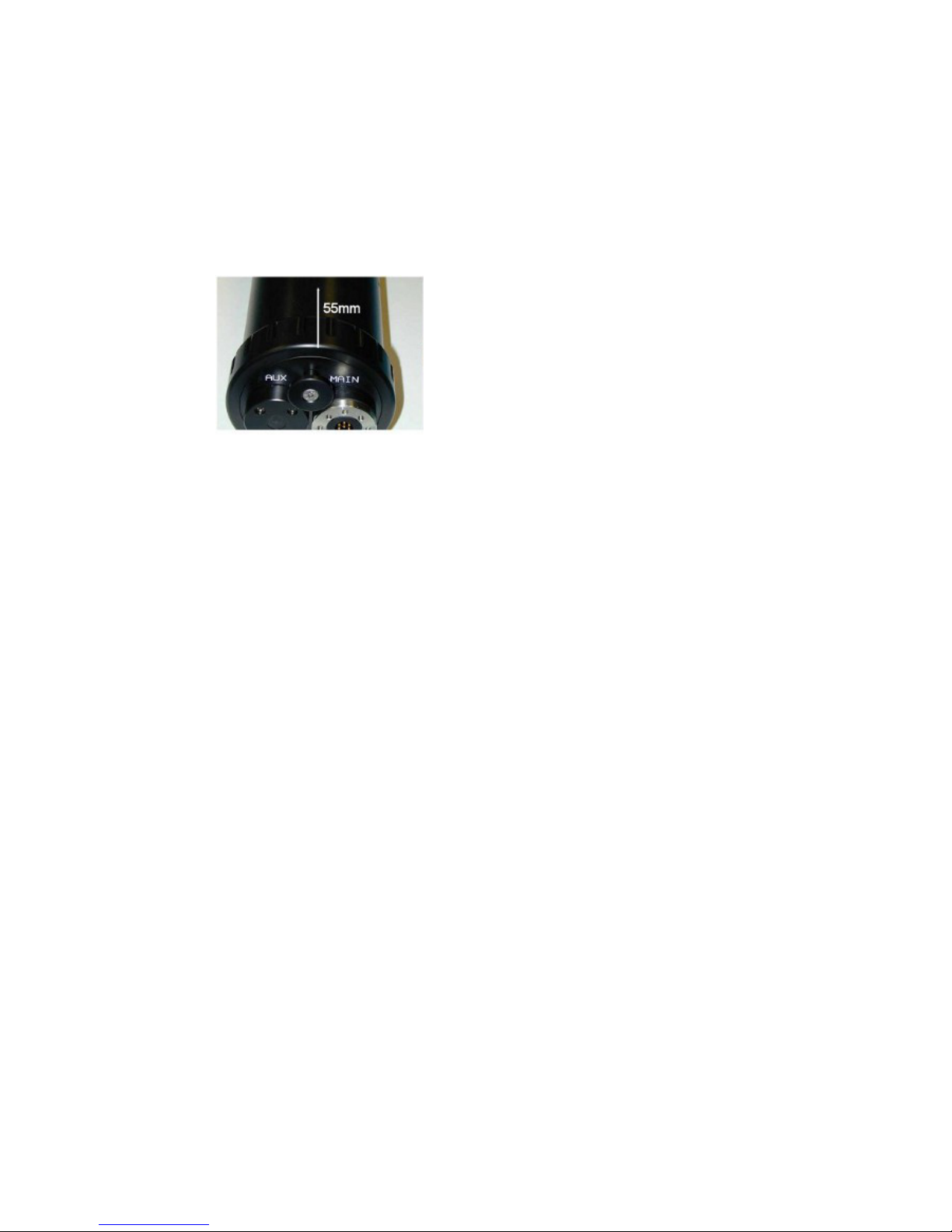
Networking COMv6 Devices SeaKing Sidecan Sonars
0374-SOM-00013, Issue: 01
78
© Tritech International Ltd.
Hard Reset
To perform a "hard reset" and force the sonar back to factory settings first turn it off
and then put a strong magnet over the case in the location indicated below. Power the
unit up with the magnet held in place and factory settings should be restored.
Measure 55mm from casing edge in-line with puller:

SeaKing Sidecan Sonars
0374-SOM-00013, Issue: 01
79
© Tritech International Ltd.
Appendix D. Marker Files
Seanet Pro includes the facility to lay a series of markers to label and track objects,
points of interest and way positions. These markers can be saved to file for the purpose
to re-load at a later date, to form part of a report or for use with the Sonar Image
Tiler program.
There are two formats of marker file:
1. A full, comma separated file format with the filename extension .mrk
2. A shortened, comma separated format with the filename extension .csv
Full Marker File Format (.mrk extension)
This is the format that is native to Seanet Pro and includes full details of the marker
configuration. The file is in an ASCII Comma Separated format and contains the
following fields:
IndexValue Description
1 ID This is a unique string ID. It comprises a 2 letter header
("mk") followed by a DateTime code. Any unique string
value is acceptable.
2 Group This is unused and should be set to 0.
3 X Coordinate For the .mrk file this will always be output in UTM
Easting.
4 Y Coordinate For the .mrk file this will always be output in UTM
Northing.
5 Altitude This is UTM Altitude and is currently unused.
6 UTM Zone Parallel Zone latitudinal letter (e.g. 'C' through 'X').
7 UTM Zone
Meridian
Zone longitudinal number (e.g 1 through 60).
8 UTM Ellipsoid Ellipsoid code (0 = Airy, 1 = Australian National, 2
= Bessel1841, 3 = Clarke 1866, 4 = Clarke 1880, 5 =
Everest, 6 = GRS80, 7 = International 1924, 8 = Modified
Airy, 9 = WGS84).
9 Point Size Applies to Circle, Square & Triangle shape types only,
otherwise set to 0.
10 Date & Time Date & Time in English(GB) Locale.
Format is "dd/mm/yyyy hh:mm:ss"
11 Shape Type 0 = Circle, 1 = Square, 2 = Triangle, 3 = Sonar Range, 4
= Preset Image (see Image Info below).

Marker Files SeaKing Sidecan Sonars
0374-SOM-00013, Issue: 01
80
© Tritech International Ltd.
IndexValue Description
12 Shape Colour Applies to Circle, Square and Triangle shape types only,
otherwise set to 00000000 (32 bit RGBA).
13 Font Inner Colour Applies to Comment Text (32 bit RGBA).
14 Font Outer Colour Applies to Comment Text (32 bit RGBA).
15 Marker Bitwise Bit 1 = Show Marker, Bit 2 = Show Coordinates, Bit 3 =
Show Comment Text (i.e. 00000111 = Show All).
16 Image Info Presets = Red Flag, Blue Flag, Green Flag, Buoy, Anchor,
Rock, Danger, POI, ViewPort, Sonar, Diver, Wheel,
Comment or MLO
Alternatively can be full path and name of an image file
(e.g. 'C:\Image1.bmp').
17 Comment Comment text.
For example, the following two markers would produce a two line .mrk file as shown:
mk41149.5595988657,0,548699.614997778,6313221.96999907,-5.3544902067987E-76,V,30,9,0,
28/08/2012 13:25:51,4,00000000,00FFFFFF,00000000,7,Red Flag,Possible Wreck Site
mk41149.5605201736,0,548724.213265236,6313198.87994614,-5.3544902067987E-76,V,30,9,0,
28/08/2012 13:27:48,4,00000000,00FFFFFF,00000000,7,Rock,WARNING! ROCKS
Shortened Marker File Format (.csv extension)
This file format is a more concise and usable format, particularly for loading a predefined target list into Seanet Pro. The file is in an ASCII Comma Separated format
and contains the following fields:

Marker Files SeaKing Sidecan Sonars
0374-SOM-00013, Issue: 01
81
© Tritech International Ltd.
IndexValue Description
1 ID This is a unique string ID. It comprises a 2 letter header
("mk") followed by a DateTime code. Any unique string
value is acceptable.
3 X Coordinate For the .csv file, will be in coordinate system used in
Seanet (either Longitude or UTM Easting).
4 Y Coordinate For the .csv file, will be in coordinate system used in
Seanet (either Latitude or UTM Northing).
17 Comment Comment text.
11 Shape Type 0 = Circle, 1 = Square, 2 = Triangle, 3 = Sonar Range, 4
= Preset Image (see Image Info below).
16 Image Info Presets = Red Flag, Blue Flag, Green Flag, Buoy, Anchor,
Rock, Danger, POI, ViewPort, Sonar, Diver, Wheel,
Comment or MLO
Alternatively can be full path and name of an image file
(e.g. 'C:\Image1.bmp').
10 Date & Time Date & Time in English(GB) Locale.
Format is "dd/mm/yyyy hh:mm:ss"
For example, the following two markers would produce a two line .csv file as shown:
mk41149.5595988657,-2.1991799999203,56.9600300036883,Possible Wreck Site,4,Red Flag,
28/08/2012 13:25:51
mk41149.5605201736,-2.19877999992026,56.9598200036882,WARNING! ROCKS,4,Rock,
28/08/2012 13:27:48

SeaKing Sidecan Sonars
0374-SOM-00013, Issue: 01
82
© Tritech International Ltd.
Glossary
.bmp The standard filename extension for bitmap images.
.kml The standard filename extension for a Keyhole Markup
Language file which contains georeferencing data. This file
will either be incorporated within a .kmz file or requires an
accompanying image file (with the same file name) to be valid.
Used by Google Earth.
.kmz The standard filename extension for a compressed file containing
the Keyhole Markup Language file (.kml) and image file. For
storing georeferencing data and images in a single file. Used by
Google Earth.
.mrk The standard filename extension for marker files exported from
Seanet Pro, saved as a text file in tabular format with table cells
separated by commas.
.png The standard filename extension for Portable Network Graphics
- a bitmapped image format employing lossless compression.
.tiff or .tif The standard filename extension for Tagged Image File Format.
.v4log The standard file format used by Seanet Pro log files.
ARCNET Attached Resource Computer NETwork - a network protocol
similar to Ethernet but with the advantage of working over much
longer ranges.
ASCII American Standard Code for Information Interchange - a
character encoding scheme originally based on the English
alphabet.
AutoComms
Hardware developed by Tritech International Ltd for use in sonar
heads which enables the sonar to automatically switch to the
correct communication protocol to match that of the surface
controller.
CD-ROM Compact Disc - Read Only Memory
CPU Central Processing Unit, the processor of a computer.
CSV Comma Separated Value - a text file in tabular format with table
cells separated by commas, usually given the filename extension
.csv but this can vary depending on the application.
DC Direct Current
DST Digital Sonar Technology

Glossary SeaKing Sidecan Sonars
0374-SOM-00013, Issue: 01
83
© Tritech International Ltd.
GeoTiff A public domain standard file format which allows
georeferencing information to be embedded into a TIFF (Tagged
Image File Format) image, uses the filename extension .tif or
.tiff.
Google Earth A virtual globe, map and geographical information program,
originally called EarthViewer 3D prior to being acquired by
Google Inc. in 2004.
GPS Global Positioning System.
JPEG or JPG Joint Photographics Expert Group - a compression method and
file format for image files, files can be stored with either .jpeg
or .jpg file extensions
Kevlar Poly-paraphenylene terephthalamide high strength, light weight,
material branded and sold as Kevlar by DuPont.
NMEA National Marine Electronics Association - a USA based
standards association responsible for overseeing electrical and
data communications standards between marine devices (due
to become the IMEA or International Marine Electronics
Association in 2012).
PC Personal Computer
PCB Printed Circuit Board
PSU Power Supply Unit
RAT Remote Access Terminal - the detachable front part of the Tritech
Surface Control Unit (SCU) computer. Provides an alternative to
using a keyboard and mouse.
ROV Remotely Operated Vehicle
RS232 Traditional name for a series of standards for serial binary data
control signals.
RS485 A standard for defining the electrical characteristics of drivers
and receivers for use in a balanced digital multipoint system (also
known as EIA-485).
RX Receive (data)
SCU Surface Control Unit - a specially manufactured computer which
is rack mountable and capable of processing the data from
the sonar equipment running either Windows XP Embedded or
Windows 7 and Seanet Pro or Gemini software.
SeaKing
A specific sonar produced by Tritech International Ltd but also
refers to the family of sonar equipment manufactured by Tritech

Glossary SeaKing Sidecan Sonars
0374-SOM-00013, Issue: 01
84
© Tritech International Ltd.
International Ltd comprising of the SeaKing, SeaKing DST
scanning and profiling sonars and the Hammerhead survey sonar.
Seanet Pro
The software supplied by Tritech International Ltd which is
capable of running all the sonar devices.
Sidescan A sonar that is typically towed behind a boat or mounted to the
side of an ROV which takes a series of narrow sonar images that
are joined together to form strips. Typically used for survey work.
Tritech waterblock
The 4000m depth rated connector developed by Tritech
International Ltd for their subsea equipment.
TX Transmit (data)
USB Universal Serial Bus.
USBL Ultra Short Base Line (positioning system)
UTC Coordinated Universal Time (time data closely related to
Greenwich Mean Time (GMT)).
UTM Universal Transverse Mercator coordinate system - a 2-
dimensional Cartesian coordinate system to give locations on the
surface of the Earth.
WGS84 World Geodetic System (1984 revision) - a standard for use in
cartography, geodesy and navigation and used as the reference
coordinate system by GPS devices.
world file A file used by the Tritech Sonar Image Tiler program which
is designed to accompany an image file and contains georeferencing data. The file format will have different extensions
depending on the format of the image file:
Image type World file
extension
.bmp .bpw
.jpg or .jpeg .jgw
.tif or .tiff .tfw
.png .pgw
XML Extensible Markup Language. A markup language and file
format that is designed to be both human and machine readable.
 Loading...