


Micron Modem
0630-SOM-00001, Issue: 01
1
© Tritech International Ltd.
Micron Modem
Product Manual
0630-SOM-00001, Issue: 01

Micron Modem
0630-SOM-00001, Issue: 01
2
© Tritech International Ltd.
© Tritech International Ltd
The copyright in this document is the property of Tritech International Ltd. The document is supplied by Tritech International Ltd on the
understanding that it may not be copied, used, or disclosed to others except as authorised in writing by Tritech International Ltd.
Tritech International Ltd reserves the right to change, modify and update designs and specifications as part of their ongoing product development
programme.
All product names are trademarks of their respective companies.

Micron Modem
0630-SOM-00001, Issue: 01
3
© Tritech International Ltd.
Table of Contents
Help & Support ........................................................................................................ 4
Warning Symbols ..................................................................................................... 5
1. Introduction .......................................................................................................... 6
2. Specification ........................................................................................................ 7
2.1. Dimensions Diagram ................................................................................ 7
2.2. Acoustic .................................................................................................... 7
2.3. Electrical and Communication ................................................................. 7
2.4. Physical ..................................................................................................... 8
2.5. Pin-out Diagram & Cable Specification ................................................... 8
3. Installation ............................................................................................................ 9
3.1. Mounting ................................................................................................... 9
3.2. Handling .................................................................................................... 9
3.3. Power ...................................................................................................... 10
3.4. Communication Protocol ........................................................................ 10
3.5. Port Layout ............................................................................................. 10
4. Operation ............................................................................................................ 12
4.1. Software .................................................................................................. 12
4.2. Integration Considerations ...................................................................... 12
4.3. Transmission Characteristics .................................................................. 13
5. Configuration ..................................................................................................... 15
5.1. Enabling Setup Mode ............................................................................. 15
5.2. Modem Configuration Window .............................................................. 16
6. Maintenance ....................................................................................................... 18
A. Testing with HyperTerminal or Docklight ....................................................... 19
B. CHIRP Signal Processing ................................................................................. 24
Glossary .................................................................................................................. 26

Micron Modem
0630-SOM-00001, Issue: 01
4
© Tritech International Ltd.
Help & Support
First please read this manual thoroughly (particularly the Troubleshooting section,
if present). If a warranty is applicable, further details can be found in a Warranty
Statement at the end of the manual.
Tritech International Ltd can be contacted as follows:
Mail
Tritech International Ltd
Peregrine Road
Westhill Business Park
Westhill, Aberdeenshire
AB32 6JL, UK
Telephone ++44(0)1224 744 111
Fax ++44(0)1224 741 771
Email support@tritech.co.uk
Website www.tritech.co.uk
Prior to contacting Tritech International Ltd please ensure that the following is
available:
1.
The Serial Numbers of the product and any Tritech International Ltd equipment
connected directly or indirectly to it.
2. Software or firmware revision numbers.
3. A clear fault description.
4. Details of any remedial action implemented.
Contamination
If the product has been used in a contaminated or hazardous environment
you must de-contaminate the product and report any hazards prior to
returning the unit for repair. Under no circumstances should a product be
returned that is contaminated with radioactive material.
The name of the organisation which purchased the system is held on record at
Tritech International Ltd and details of new software or hardware packages will be
announced at regular intervals. This manual may not detail every aspect of operation
and for the latest revision of the manual please refer to www.tritech.co.uk
Tritech International Ltd can only undertake to provide software support of systems
loaded with the software in accordance with the instructions given in this manual. It
is the customer's responsibility to ensure the compatibility of any other package they
choose to use.

Micron Modem
0630-SOM-00001, Issue: 01
5
© Tritech International Ltd.
Warning Symbols
Throughout this manual the following symbols may be used where applicable to
denote any particular hazards or areas which should be given special attention:
Note
This symbol highlights anything which would be of particular interest to
the reader or provides extra information outside of the current topic.
Important
When this is shown there is potential to cause harm to the device
due to static discharge. The components should not be handled without
appropriate protection to prevent such a discharge occurring.
Caution
This highlights areas where extra care is needed to ensure that certain
delicate components are not damaged.
Warning
DANGER OF INJURY TO SELF OR OTHERS
Where this symbol is present there is a serious risk of injury or loss of life.
Care should be taken to follow the instructions correctly and also conduct
a separate Risk Assessment prior to commencing work.

Micron Modem
0630-SOM-00001, Issue: 01
6
© Tritech International Ltd.
1. Introduction
The Tritech International Ltd Micron Data Modem provides a means of transferring
data acoustically through water. Operation is point to point, between a pair of
Micron Data Modems, at operational distances of up to 500m horizontally and 150m
vertically at a data rate of 40 bits per second.
Devices are addressed through a serial electrical interface, which may be controlled
directly from a personal computer with a simple teletype (half-duplex) terminal
program.
Spread Spectrum Technology
The quality of acoustic data transmission in water using conventional single
frequency systems suffers considerably from multi-path phenomena. Sound
transmitted from the sending modem arrives at the receiving unit via the direct path,
and via a series of secondary paths, due to reflections from the sea surface and sea
bottom. This can often result in the loss or corruption of transmitted data.
In addition, conventional systems have poor immunity to the continuously varying
background sea noise (such as wave noise).
Tritech Spread Spectrum technology however does not concentrate the acoustic
energy in one waveband, but produces a transmission which is linearly varied between
20kHz and 24kHz (known as a CHIRP waveform). By correlating the received
signals with the CHIRP waveform it is possible to achieve superior performance in
challenging multi-path environments.
In addition, identification of a unique transmission signature allows signals to be
detected in extremely noisy conditions, to the extent that communication is successful
even when the signal to noise ratio is as low as -6dB. This means that data streams can
be successfully detected which are considerably below the background noise level.

Micron Modem
0630-SOM-00001, Issue: 01
7
© Tritech International Ltd.
2. Specification
2.1. Dimensions Diagram
79
Ø50
56
68
Ø56
Not to scale, dimensions in mm.
2.2. Acoustic
Frequency band 20 - 28kHz
Data rate
40bit·s-1 (spread spectrum)
Range 500m horizontal, 150m vertical
Transmitter source 169dB re 1μPa at 1m
Doppler tolerance
±5m·s
-1
Minimum signal to noise ratio -6dB (in band)
Multipath rejection Maximum delay spread of 10 - 100ms
Ranging Integral range function with 0.1m resolution
over full range and ±0.2m accuracy
(assuming correct velocity of sound)
2.3. Electrical and Communication
Communications protocol RS232 or RS485
Power supply 12 - 24V DC
Power consumption 7.92W (330mA at 24V) transmitting
0.72W (30mA at 24V) receiving
Specification Micron Modem
0630-SOM-00001, Issue: 01
8
© Tritech International Ltd.
2.4. Physical
Weight in air 235g
Weight in water 80g
Depth rating 750m
Temperature range -10 to 35°C (-20 to 50°C in storage)
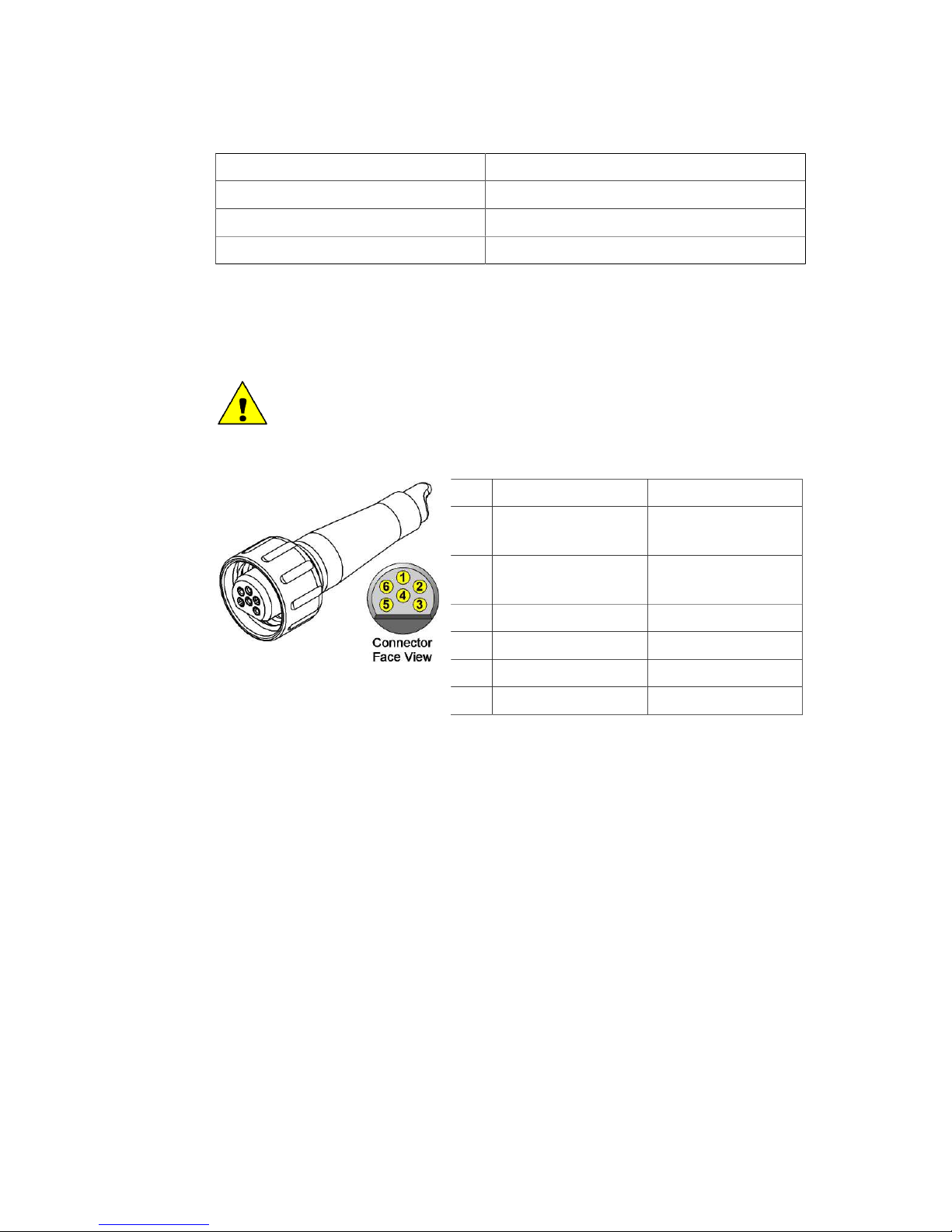
2.5. Pin-out Diagram & Cable Specification
Caution
The Micron series connector is not wet mateable and direct exposure to
water when the unit is powered will cause damage.
Pin Wire Colour Function
1 Yellow RS485 A (-)
RS232 TX
2 Blue RS485 B (+)
RS232 RX
3 Red DC +
4 Black DC ground
5 Green RS232 ground
6 cable sheath earth

Micron Modem
0630-SOM-00001, Issue: 01
9
© Tritech International Ltd.
3. Installation
3.1. Mounting
Orientation of the Micron Data Modem will normally be in the vertical position with
the transducer uppermost. The transducer is omni-directional.
Four tapped holes in the aluminium body are provided by the bottom of the Micron
Modem to permit mounting on flat surfaces, alternatively the Modem may be gently
gripped by a 50mm diameter clamping mechanism around the bottom part of the
housing.
Caution
It is recommended that any fixing screws used should be of a non-metallic
material to reduce the risk of corrosion around the fixing positions.
All dimensions are in millimetres.
Figure 3.1. Mounting Holes on Micron Range
3.2. Handling
The Micron Data Modem is a sealed product and under no circumstances should it be
opened or tampered with in any way. There are no user-serviceable parts or internal
switches which would necessitate disassembly.
The connector socket is not usable "open face" and should always be sealed wither
with a connector plug or the blanking plug provided. The auxiliary port should be
blanked off at all times when not in use.

Installation Micron Modem
0630-SOM-00001, Issue: 01
10
© Tritech International Ltd.
3.3. Power
The Micron Data Modem should be powered from a clean DC supply or battery pack.
To reduce damage to the device in the event of over-voltage it is recommended that
an appropriate fuse is included in the power supply connection.
For full details of the power requirement refer to Chapter 2, Specification.
3.4. Communication Protocol
The Micron Data Modem is supplied with two communications ports labelled MAIN
and AUX (short for auxiliary). All communication to the control computer on the
surface should be via the MAIN port.
The communication protocols used by the ports are factory set and are not user
selectable other than at the time of build.
• The RS232 telemetry is bi-directional, 3-wire (TX, RX and ground) between the
data modem and the controlling serial port.
• The RS485 telemetry is half-duplex, 2-wire (RS485+ and RS485-). Typically the
controlling RS485 connection can be an RS485 serial port installed in a computer
or can be an RS485 to RS232/USB signal converter. The RS485 circuit inside the
Micron Modem is factory supplied with a 150Ω termination.
A pair of Micron Data Modems can be connected between two serial devices in order
to transfer data between them acoustically.
For pin-out and cable specification refer to Chapter 2, Specification
3.5. Port Layout
The Micron Modem is supplied with two communications ports labelled MAIN and
AUX. All communication to the control computer on the surface should be via the
MAIN port, while the AUX port is used for daisy chained communication links to other
Tritech International Ltd sensors, such as the Micron Echosounder.
The communication configuration of the ports are factory set. The factory setting is
written on the label attached to the Micron, and can also be obtained from the original
build record.
Any combination of protocols (RS232 and RS485 only) are possible and Tritech
International Ltd use the letters A to D to denote the factory settings:

Installation Micron Modem
0630-SOM-00001, Issue: 01
11
© Tritech International Ltd.
ID MAIN AUX Label Example
A RS485 RS485
B RS232 RS485
C RS485 RS232
D RS232 RS232
Note
If the settings are changed through software it is important to keep a record
of the changes, otherwise it can be difficult to re-connect to the modem.
Micron Modem
0630-SOM-00001, Issue: 01
12
© Tritech International Ltd.
4. Operation
4.1. Software
Tritech International Ltd does not supply the Micron Data Modem with specific
operating software. Seanet Pro software is required should any modem reconfiguration be required (refer to Chapter 5, Configuration).
Any terminal software may be used to operate and test a pair of data modems,
however, they will normally be used as part of a larger system, the hardware of which
will take control of the data transfer process
The Micron Data Modem is configured to communicate on RS232 at 9600Bd, 8 data
bits, 1 stop bit and no parity by default. Other rate options are possible although the
device is not configurable once in the field. If the settings of a particular device are
unknown contact Tritech International Ltd Technical Support providing the serial
number and any of the original purchase details (if known).
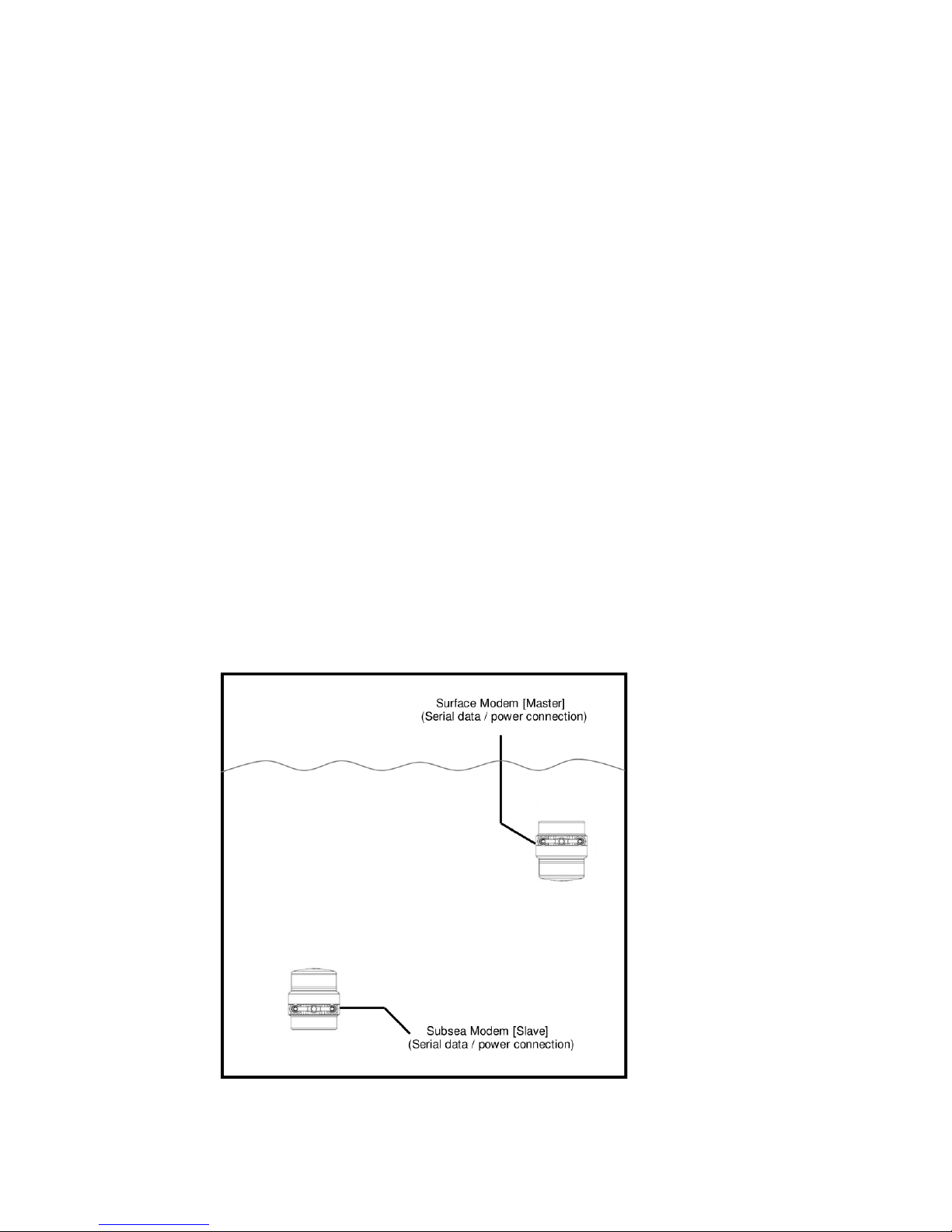
4.2. Integration Considerations
A pair of Micron Data Modems may be used in the following basic configuration:
Figure 4.1. Pair of Micron Modems in Use

Operation Micron Modem
0630-SOM-00001, Issue: 01
13
© Tritech International Ltd.
The following points should be noted:
• The terms "Master" and "Slave" in Figure 4.1, “Pair of Micron Modems in Use”
are used purely as an aid to system description. Either unit can transmit to and
receive from the second unit. The operating distinction between a master and slave
is that each uses a separately coded CHIRP to avoid a unit receiving a close echo
of its own transmission.
• The Micron Data Modem acoustic communication link provides a serial data
transmission path through water.
• The Micron Data Modem has an internal buffer of 256 bytes. The incoming serial
data rate must take into account of the acoustic transmission rate of 40bit·s-1 and
this buffer size.
• The acoustic radiation pattern is approximately omni-directional, and the modem
will operate in both horizontal and vertical attitudes.
• Data modems should not be placed close to any acoustically reflecting surfaces,
such as a boat hull or the sea/seabed surface, ideally providing a separation of at
least 1m.
•
Each Micron Modem is capable of withstanding Doppler shifts of up to ±5m·s-1.
• No unique addressing function is provided. A slave modem can communicate with
a master modem only, with a master modem capable of broadcasting data to all
slave modems within operational range.
• Data control is not provided by the Micron Data Modem. For instance simultaneous
transmissions from both modems in a pair may not result in transmission receipt
by either modem. Control of the Micron Modem must be handled by the connected
computer or hardware.
• Error checking and data quality is not provided by the Micron Modem. Any error
in transmission will not be detected by the Modem and the Modem will not attempt
re-transmission of the same data should it not be received correctly by the receiving
Modem.
• The RNG function command can be used to calculate the distance acoustically
between the two Modems with a resolution of 0.1m and an accuracy of 0.2m
4.3. Transmission Characteristics
Transmission characteristics are depended on a variety of operating conditions which
may significantly reduce operating range:
• The presence of thermoclines
• The presence of acoustically reflecting surfaces within the operating environment

Operation Micron Modem
0630-SOM-00001, Issue: 01
14
© Tritech International Ltd.
• Ambient noise
• Salinity
• Volume reverberation
• Surface and seabed reflectivity
• Significant Doppler shifts present, due to the relative movement between two
communicating Modems.

Micron Modem
0630-SOM-00001, Issue: 01
15
© Tritech International Ltd.
5. Configuration
5.1. Enabling Setup Mode
Ensure the Modem is powered off and the PC serial port connected to the Modem is
enabled, set to a baud rate of 57600Bd
Launch Seanet Setup and navigate to Com Setup from the Utilities menu. In
the dialog that is displayed make sure that the device Aif is enabled and using the
correct COM port that is connected to the Micron Modem (the Status column
should read Not Available until the Micron Modem is turned on).
Power on the modem while holding a magnet to the side of the housing as indicated
in Figure 5.1, “Location of Reset Switch (activated by magnet)”.
Figure 5.1. Location of Reset Switch (activated by magnet)
Once the Micron Data Modem has started it will be listed as node number 85 in the
Seanet Setup node table and should be labelled as MINIMODEM.
From here it is possible to select Setup from the Action column to enable the
setup mode for the Micron Modem. This is illustrated in Figure 5.2, “Enter Micron
Modem Setup”.
Figure 5.2. Enter Micron Modem Setup

Configuration Micron Modem
0630-SOM-00001, Issue: 01
16
© Tritech International Ltd.
5.2. Modem Configuration Window
From the node table in Seanet Setup select Setup from the action column of the row
which shows the Micron Modem. This will bring up the AM100ModemCfgSetup
dialog as shown in Figure 5.3, “Micron Modem Configuration”.
Figure 5.3. Micron Modem Configuration
The AM100ModemCfgSetup dialog allows the following settings to be changed:
Note
Test Msg, Ranging and Responder all must be entered in lower
case characters followed by a line feed command and no carriage return
terminator.
Unit OpMode Select Surface Modem or SubSea Modem
(Transponder and Responder are not applicable to the
Micron Data Modem).
COM Rx TMO
Enabled
This option should always be selected to prevent data loss.
Test Msg (stm) When selected, on receipt of an stm<LF> string the receiving
modem responds with the message: Hello!!! This is
a test message using spread spectrum at
40bps
Ranging (rng) When selected on receipt of an rng<LF> string the receiving
modem responds with a transmitted CHIRP allowing the first
modem to calculate the total transmission time, and hence the
intervening distance in metres. This is displayed as a range
value between the two modems.

Configuration Micron Modem
0630-SOM-00001, Issue: 01
17
© Tritech International Ltd.
Responder (png) When selected on receipt of a png<LF> string, the receiving
modem responds with an acoustic CHIRP - used for
diagnostics only.
Force 4 Mode Forces Setup mode to be entered without using a magnet
during power-up operation.
Save Cfg Saves the current set of settings to a configuration file.
Load Cfg Loads a set of settings from a configuration file.
Baud Rates
Caution
The Hi Speed 57600 setting in Async 0 (Serial
LAN AUX 1) section must not be altered - the
magnetic reset does not reset the baud rates).
This button will load the Comms Setup dialog. The only
field that should be altered is indicated in Figure 5.4, “Comms
Setup Dialog”.
Figure 5.4. Comms Setup Dialog
To change the setting
1. Select the required baud rate from the list in the field
indicated in Figure 5.4, “Comms Setup Dialog”.
2. Press OK on the Comms Setup dialog.
3. Press OK on the AM100ModemCfgSetup dialog and the
changes made will be programmed into the modem.
Note
Any parameters not listed above are not effective at present and should
not be selected or changed from the factory defaults.

Micron Modem
0630-SOM-00001, Issue: 01
18
© Tritech International Ltd.
6. Maintenance
There are no user serviceable components in the Micron Modem and there is no
reason to dismantle the device.
Wash down with fresh water each time the Micron Modem is recovered from the
water, paying particular attention to the transducer and connector.
Although the Micron Modem is designed for a wide temperature range it is best
to avoid temperature extremes for long periods and protect the device from bright
sunlight.
It is recommended that usage logs are maintained and that the heads are returned to the
vendor at 4000 hour intervals for routine inspection and replacement of o-ring seals.
Any cables that are supplied with the Micron Modem are high quality with low
halogen jackets and should provide long service life without problems. Care should
be taken to ensure that they are properly sited during installation to avoid movement
and fatigue but otherwise no maintenance is required.

Micron Modem
0630-SOM-00001, Issue: 01
19
© Tritech International Ltd.
Appendix A. Testing with HyperTerminal or
Docklight
The Micron Data Modems can be bench tested in air using any terminal program.
Typically the modems being tested should be no further than about 20-30cm apart
with a clear line of sight present between the blue potted transducer on each modem.
If the modems are too far apart in air then corruption of the ASCII message will occur
or no data will be received by the second modem.
HyperTerminal
1. Open HyperTerminal (if this is installed, it will be located in the Windows Start
Menu).
2. Enter the name for the Terminal window and then click OK:
3. Next select the COM port number of the port that the first modem is connected
to and click OK.

Testing with HyperTerminal or Docklight Micron Modem
0630-SOM-00001, Issue: 01
20
© Tritech International Ltd.
4. Ensure that the Bits per second (baud rate) is set correctly for the modem
(9600 is default) and set the flow control to None.
5. Within the main Terminal window click on the Call drop down menu and
select Disconnect. Then click on the File drop down menu and select
Properties. Click on the Settings tab at the top of the window and click
the ASCII Setup button.
6. Ensure that the Send line ends with line feeds and Echo typed
characters locally options are checked and click OK to apply the settings
and then click OK on the properties dialog.

Testing with HyperTerminal or Docklight Micron Modem
0630-SOM-00001, Issue: 01
21
© Tritech International Ltd.
7. Repeat steps 1-6 to create another terminal window for the second modem.
8. Using the mouse to click one terminal window into focus, any typed ASCII
message will be transmitted acoustically from one modem to the second modem.
With the Master/Slave modem configuration, multiple Slave modems can be
connected and tested in HyperTerminal with one Master modem. The Master
modem ASCII message is broadcast to all Slave modems in range and each Slave
modem message is only received by the Master modem.

Testing with HyperTerminal or Docklight Micron Modem
0630-SOM-00001, Issue: 01
22
© Tritech International Ltd.
Docklight
Note
The version in use here is Docklight V1.9. Docklight is available from
www.docklight.de">.
1. Within the Send Sequences box double click on the grey box in the Name
column to enter the Edit Send Sequence dialog.
2. Next fill in the commands for Test Message, Ranging and Responder
(clicking Apply after each command) and use the Index selection arrows at the
top of the window to switch to the next command window and then click OK to add
them. The main window should now be shown as below with the three function
commands entered:
3. The COM port that the Micron Data Modem is attached to needs to be configured.
Double click on the COM port number in the top right hand corner of the main
window which will open the Project Settings dialog. Within this dialog
select the appropriate COM port for the modem to be used. Ensure the baud rate
is set to match the modem (9600 by default) and that the Send/Receive option
is selected.

Testing with HyperTerminal or Docklight Micron Modem
0630-SOM-00001, Issue: 01
23
© Tritech International Ltd.
4. For testing the Micron Data Modem the COM port that the Master is connected
to should be selected in Docklight first and used to send the function commands
and check that the appropriate command response is received. Then the COM port
that the Slave is connected to should be selected and the commands sent again.
This will check that both modems can send and receive commands. An example
output is shown:

Micron Modem
0630-SOM-00001, Issue: 01
24
© Tritech International Ltd.
Appendix B. CHIRP Signal Processing
There are several advantages of Tritech International Ltd Digital Sonar Technology
(DST) which allows the use of CHIRP signal processing technology in order to
improve the images generated by the sonar.
In monotonic (single frequency burst) sonar, the range resolution is determined by
the length of the transmitted pulse. The smaller the pulse is, the greater the resolution
achievable and vice-versa. The smallest pulse length is typically 50 micro seconds
and velocity of sound in water is approximately 1500 metres/second which gives a
range resolution of 37.5mm. This result effectively determines the ability to resolve
separate targets.
Target
Seperation
T1
T2
Time
Transmitted Pulse
Target 1 echo
Target 2 echo
Sonar range
resolution
Target
seperation
Combined echo
(seen by the receiver)
Using the example above, if two targets are less than 37.5mm apart then they cannot
be distinguished from each other. The net effect is that the system will display a single
large target, rather than multiple smaller targets.
CHIRP signal processing overcomes these limitations by sweeping the frequency
within the burst over a broad range of frequencies throughout the duration of
transmission pulse. This creates a signature acoustic pulse - the sonar knows what
was transmitted and when. Using pattern-matching technology, it can now look for
its own unique signature being echoed back from targets.
Transmitted signal
Transmitter
circuit
Receiver
circuit
Received decoded signal
pulse duration
In a CHIRP system, the critical factor determining range resolution is now the
bandwidth of the CHIRP pulse which means the range resolution is given by:
Range resolution =
velocity of sound
2 x bandwidth
The bandwidth of a typical Tritech International Ltd CHIRP system is 50kHz

CHIRP Signal Processing Micron Modem
0630-SOM-00001, Issue: 01
25
© Tritech International Ltd.
With velocity of sound in water of 1500m/s this gives a new range resolution of
15mm.
This time, when two acoustic echoes overlap, the signature CHIRP pulses do not
merge into a single return. The frequency at each point of the pulse is different, and
the sonar is able to resolve the two targets independently.
Target
Seperation
T1
T2
Time
Transmitted Pulse
Target 1 echo
Target 2 echo
Sonar range
resolution
Target
seperation
Combined echo
Both targets
are visible.
The response from the pattern-matching algorithms in the sonar means that the length
of the acoustic pulse no longer affects the amplitude of the echo on the sonar display.
Longer transmissions (and operating ranges) can be achieved without a loss in range
resolution.
Additionally CHIRP offers improvements in background noise rejection, as the sonar
is only looking for a swept frequency echo, and removes random noise or out-ofband noise.

Micron Modem
0630-SOM-00001, Issue: 01
26
© Tritech International Ltd.
Glossary
ASCII American Standard Code for Information Interchange - a
character encoding scheme originally based on the English
alphabet.
CHIRP Compressed High Intensity Radar Pulse - a technology for
improving image resolution initially used in radar systems but
also adapted to sonar devices.
DC Direct Current
RS232 Traditional name for a series of standards for serial binary data
control signals.
RS485 A standard for defining the electrical characteristics of drivers
and receivers for use in a balanced digital multipoint system (also
known as EIA-485).
RX Receive (data)
TX Transmit (data)
USB Universal Serial Bus.
 Loading...