

Page 1
C SERIES
PUMP
Installation Instructions
IMPORTANT SAFETY INSTRUCTIONS
READ AND FOLLOW ALL INSTRUCTIONS
SAVE THESE INSTRUCTIONS
Table of Contents
SECTION I. MOTOR REMOVAL. ............................................................................................ 2
SECTION II. MOTOR INSTALLATION PROCEDURES ......................................................... 2
SECTION III. PARTS LIST C SERIES PUMPS. ......................................................................... 3
SECTION IV. C SERIES PUMP CURVES ..................................................................................4
™
WARNING
Before installing this product, read and follow all warning notices and instructions accompanying this pump.
Failure to follow safety warnings and instructions can result in severe injury, death, or property damage.
Call (800) 831-7133 for additional free copies of these instructions.
Important Notice
Attention Installer.
This manual contains important information about the installation, operation and safe use of this
product. This information should be given to the owner/operator of this equipment.
WARNING
Risk of electrical shock or electrocution.
This pool pump must be installed by a licensed or certified electrician or a qualified pool
serviceman in accordance with the National Electrical Code and all applicable local codes and
ordinances. Improper installation will create an electrical hazard which could result in death or
serious injury to pool users, installers, or others due to electrical shock, and may also cause
damage to property.
Always disconnect power to the pool pump at the circuit breaker before servicing the pump.
Failure to do so could result in death or serious injury to serviceman, pool users or others due to
electric shock.
Pentair Pool Products
1620 Hawkins Ave., Sanford, NC 27330 • (919) 774-4151
10951 West Los Angeles Ave., Moorpark, CA 93021 • (805) 523-2400
Rev. D 7-17-02 1 P/N 075277
Page 2
CAUTION
To reduce the risk of injury, do not permit children to use this product unless they are closely supervised at all times.
CAUTION
DO NOT OPERATE THIS UNIT DRY. Operating this unit dry will damage the shaft seal which will cause the pump to leak.
CAUTION
Motor must be wired as indicated on motor diagram. (See box cover and nameplate). Refer to 'Motor Rotation Check'
for correct pump rotation. Incorrect rotation can damage the pump.
Three Phase Motors are NOT thermally protected. MUST be installed in conjunction with a Magnetic Starter
equipped with Thermal Overload Protection.
SECTION I. MOTOR REMOVAL.
1. Support motor on both sides. Remover four hex head cap screws (22) that hold motor to volute (7).
2. Carefully and slowly pull motor (23) until seal flange (17) and impeller (15) are completely out of the volute (7).
Avoid resting entire unit on seal flange or impeller.
3. Remove Allen head cap screw (12) and washer (13) from center of impeller (15). Pull impeller from shaft.
Do not lose square key (21).
4. Remove seal spring member (16) from shaft. Avoid cutting rubber parts or scratching carbon face.
5. Remove two hex head cap screws (19) from seal flange (17). Hold seal flange so that it does not drop on motor
shaft while removing screws. Remove seal flange.
6. Remove ceramic seal face member (16) from center of seal flange (17) and o-ring (18) from grove.
Check for nicks and cuts. Replace as necessary.
7. Finally, remove water slinger (20) if replacing with new one or servicing motor.
SECTION II. MOTOR INSTALLATION PROCEDURES.
1. Slip water slinger (20) on motor shaft past shoulder.
2. Press ceramic seal face member (16) into center cavity of seal flange (17) with the smooth ceramic facing out.
Clean and grease o-ring (18) and place in seal flange groove.
NOTE
MAKE SURE THAT CERAMIC FACE IS FREE FROM OIL OR GREASE.
3. Install seal flange on motor register and secure in place with two cap screws (19).
4. Press seal spring member (16) on motor shaft with carbon face towards ceramic seal member.
Avoid cutting rubber parts on shaft.
5. Line up keyways and push impeller (15) on motor
shaft up to shoulder. Insert square key (21) in
place.
6. Secure impeller with washer (13) and Allen head
cap screw (12).
7. Position and carefully install assembled motor
until to the volute (7) and secure motor using cap
screws (22).
8. Remove motor shaft and cap. Momentarily, start
and stop motor - while impeller is still turning,
check end shaft rotation. Rotation must be in the direction indicated by the arrow on the outside of the
volute (7). Fill strainer pot with water, install basket, and secure cover. Pump is ready for operation.
Press in motor shaft end cap.
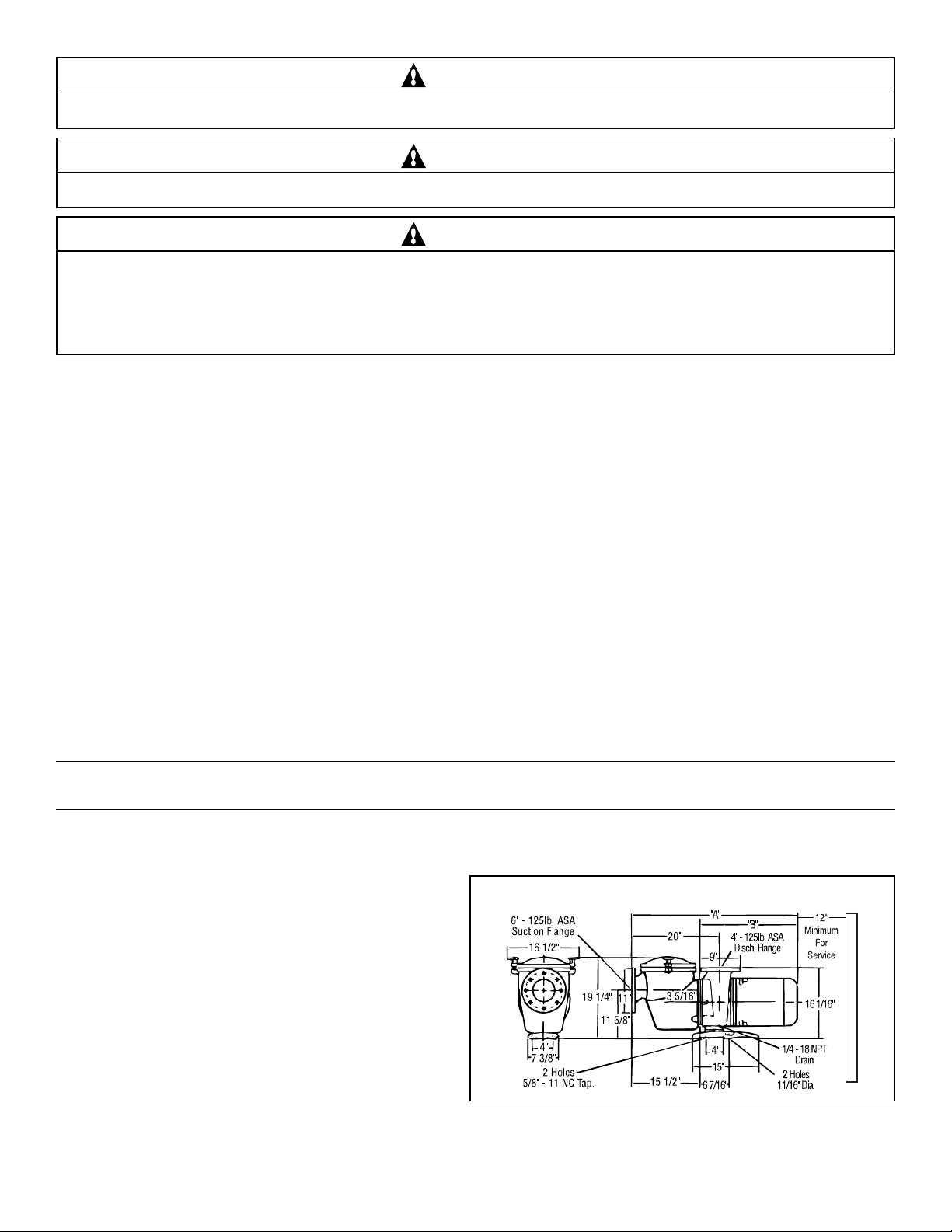
C SERIES PUMP DIMENSIONS
P/N 075277 2 Rev. D 7-17-02
Page 3

SECTION III. PARTS LIST C SERIES PUMPS.
1
2
4 in.
Discharge
Volute
3
Flange
14
6
13
12
15
16
17
18
21
23
20
22
8
7
4
6 in.
Pot
Suction
Flange
9
5 in.
5
4
Suction
Volute
Flange
11
10
Item Part Reference Description
No. No. No.
1 075280 54475281199 Hand nut assy. - brass, 2 req.
2 075275 26075275219 Cover, C-16 - brass
3 071433 3640525457 O-ring C-18
4 071551 6000002190 Plug pipe ¼ in. brass, 2 req.
5 075271 79675271199 Pot mach. strain brass C-22
6 072795 70472795100 Basket, C-29 s/s 11 in.
7 075273 18075273199 Volute C-2 brass
8 070943 36470943603 Gasket flange P-135-5 in.
9 071683 1680634104 Screw ¾ in. - 10 x 1¾ in. HH brass P-12, 4 req.
10 075287 82075287632 Foot C-4 cast iron - coated
11 071688 1680558359 Screw 5/8 -11 x 1 s/s HH, 2 req.
12 071037 1680115104 Imp.-C-35 lock screw
13 071048 90871048212 Imp. washer C-71
14 356631 3642034603 Imp. washer gasket
15 073828 44473328208 Imp CH-50/CHK-50/CHKL-50 - 5hp, single, 3ph, high head
15 070228 44470228208 Imp CM-50/CMK-50/CMKL-50 - 5hp, single, 3ph, med. head
15 073829 44473829208 Imp CHK-75/CHK-75/CHKL-75 - 7.5hp, single, 3ph, high head
15 070227 44470227208 Imp CM-75/CMK-75/CMKL-75 - 7.5hp, single, 3ph, med. head
15 073830 44473830208 Imp CHK-100/CHKL-100 -10hp, 3ph, high head
15 070226 44470226208 Imp CMK-100/CMKL-100 -10hp, 3ph, med. head
15 073831 44473831208 Imp CHK-150/CHKL-150 -15hp, 3ph, high head
15 070225 44470225208 Imp CMK-150/CMKL-150 -15hp, 3ph, med. head
15 073832 44473832208 Imp CHK-200/CHKL-200 - 20hp, 3ph, high head
16 071725 71271725753 Seal (C-7) PS-360
17 070906 11670906199 Flange, mach.-C-52 brass
18 071423 3640508457 O-ring, C-70
19 071681 1680378104 Screw 3/8 - 16 x ¾ in. CS HH, 2 req.
20 072185 7641043478 Water slinger C-115
21 071046 4720201104 Impeller key 3/16 in. sq.
22 071687 1680155113 Screw ½ in. - 13 x 1¼ in. std. HH, 4 req.
60 HERTZ MOTORS
23 357205 Motor 5 hp,1ph, 200/208v
23 071366 52571366999 Motor 5hp, 1ph, 230v
23 357206 Motor 5hp, 3ph, 200/208v
23 071364 52571364999 Motor 5hp, 3ph, 220/440v
23 357237 Motor 5hp, 3ph, 575v
23 357207 Motor 7.5hp, 1ph, 200/208v
23 357204 525357204999 Motor 7.5hp, 1ph, 230v
23 357208 Motor 7.5hp, 3ph, 200/208v
23 071365 52571365999 Motor 7.5hp, 3ph, 220/440v
23 357247 Motor 7.5hp, 3ph, 575v
19
All motor subassemblies are 60 Hertz 220/440v, 3 Phase
EXCEPT 073264 and 073260 which are 230v only.
All motor subassemblies are single phase 60 Hertz.
All motor subassemblies are 50 Hertz 380/415v, 3 Phase.
Notes:
All brass C Series parts will retrofit older cast iron models.
Standard flange not included with pump.
Item Part Reference Description
No. No. No.
60 HERTZ MOTORS (Cont'd.)
23 357209 Motor 10hp, 3ph, 200/208v
23 071363 52571363999 Motor 10hp, 3ph, 220/440v
23 357238 Motor 10hp, 3ph, 575v
23 071361 52571361999 Motor 15hp, 3ph, 220/440v
23 357245 Motor 15hp, 3ph, 575v
23 071362 52571362999 Motor 20hp, 3ph, 220/440v
23 357246 Motor 20hp, 3ph, 575v
50 HERTZ MOTORS
23 072737 52572737999 Motor 5hp, 3ph, 380/415v
23 072739 52572739999 Motor 7.5hp, 3 ph, 380/415v
23 072740 52572740999 Motor 10hp, 3 ph, 380/415v
23 072742 52572742999 Motor 15hp, 3 ph, 380/415v
23 072744 52572744999 Motor 20hp, 3 ph, 380/415v
Motor sub assemblies include items #12 thru #23.
073260 Motor sub assy. CM-50
073264 Motor sub assy. CH-50
073262 Motor sub assy. CMK-50
073265 Motor sub assy. CHK-50
073263 Motor sub assy. CMK-75
073266 Motor sub assy. CHK-75
073680 Motor sub assy. CMK-100
073267 Motor sub assy. CHK-100
073261 Motor sub assy. CMK-150
073268 Motor sub assy. CHK-150
073269 Motor sub assy. CHK-200
357905 Motor sub assy. CM-75, 1ph, 230v
357910 Motor sub assy. CH-75, 1ph, 230v
357930 Motor sub assy. CM-75, 1ph, 200v
357935 Motor sub assy. CH-75, 1ph, 200v
014700 Motor sub assy. CMKL-50, 380/415v
014801 Motor sub assy. CHKL-50, 380/415v
014701 Motor sub assy. CMKL-75, 380/415v
014802 Motor sub assy. CHKL-75, 380/415v
014702 Motor sub assy. CMKL-100
014803 Motor sub assy. CHKL-100
014703 Motor sub assy. CMKL-150
014804 Motor sub assy. CHKL-150
014805 Motor sub assy. CHKL-200
Rev. D 7-17-02 3 P/N 075277
Page 4

SECTION IV. C SERIES PUMP CURVES
TOTAL DYNAMIC HEAD IN FEET OF WATER
FLOW RATE IN GPM
TOTAL DYNAMIC HEAD IN FEET OF WATER
FLOW RATE IN GPM
SAVE THESE INSTRUCTIONS.
Pentair Pool Products
1620 Hawkins Ave., Sanford, NC 27330 • (919) 774-4151
10951 West Los Angeles Ave., Moorpark, CA 93021 • (805) 523-2400
P/N 075277 4 Rev. D 7-17-02
 Loading...