

Page 1

TRISCO TECHNOLOGY CORP.
8F, No.45, Fu Hsing South Road Sec. 2,
Taipei 106, Taiwan, R.O.C
Tel: 886-2-2703 7031 Fax: 886-2-2325 4076
Http//www.trisco.com
E-mail: [email protected]
2010 Trisco Technology Corp. All rights reserved.Ver.1.0
P/N: 244.144 (A)
R-456
6-Function Analyzer
User’s Manual
Page 2
ENGINE ANALYZER INSTRUCTION MANUAL
An engine analyzer is an indispensable companionshio to an automechanic, regardless if he is a
“Sunday machanic” or a professional.
Warning : To avoid body injuries and damages to the tester, use extreme care when working under the
hood. Do not touch any moving parts or hot surfaces of the engine.
If you will take a few moments to read through the following informations and get yourself familiar with
your new tester, we are sure you can enjoy many years of its service and through its use, the engine
efficiency of your car will be increased highly.
Note : For all the following tests, unless otherwise stated, the engine should be at normal operating
temperature and running at idle speed.
TACHOMETER FUNCTION
Although the Tachometer will give out only RPM readings, judicious use of this function will provide much
more :
1. Connecting the analyzer:
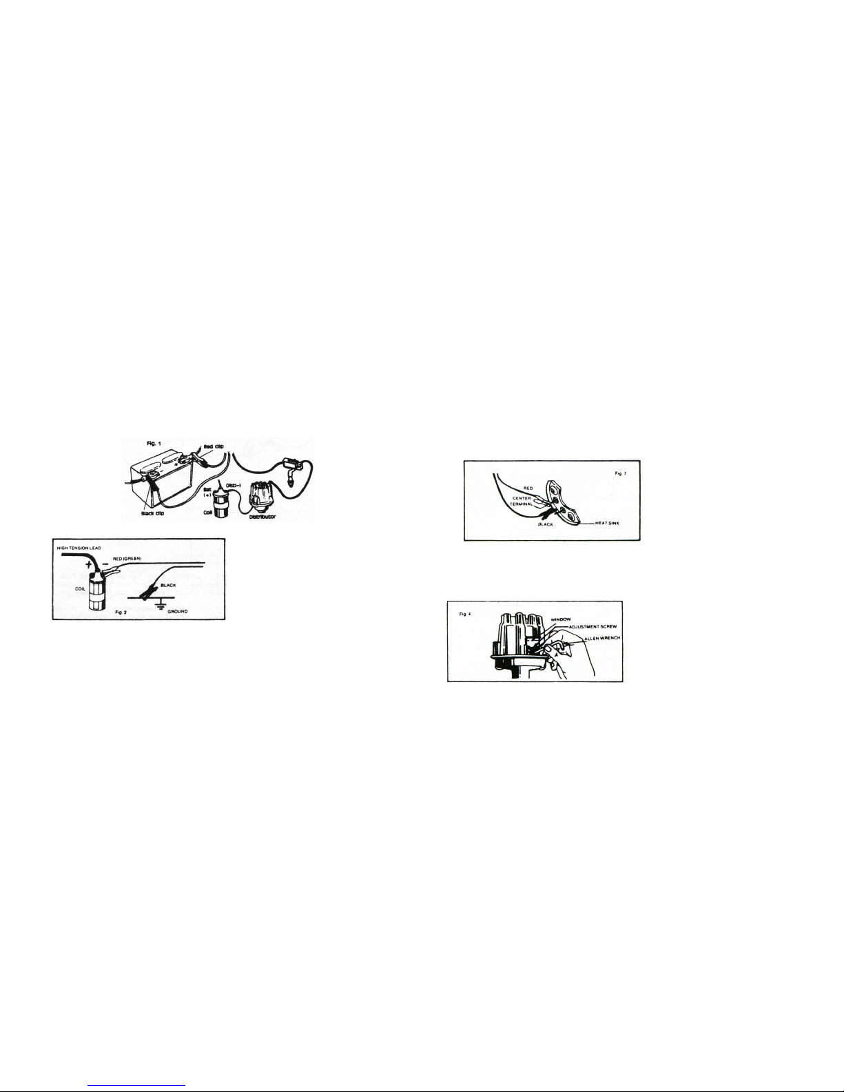
a. Model equipped with an inductive pick-up (see fig. 1)
b. Model only with two test leads. (see fig. 2)
● Connect Black clip to (-) post of the battery or any part of the engine which is relied to (-) of the
battery.
● Connect red (green) clip to (-) post of the ignition coil.
● Move the Cylinder switch selection to the correct position in accordance with the number of
your car cylinder.
2. Zero adjustment :
Before each use verify your analyzer reads “0”, if not, proceed as following:
● Hold the instrument in normal use position, adjust the screw in front of the meter until it reads “0”
on tach scale.
IDLE ADJUSTMENT:
1. Set the analyzer at LO-TACH.
2. Turn the Idle MIXTURE screw in until the engine begins to fall off, turn the screw out until the engine
again begins to fall off, then adjust the screw between these two points to get the highest RPM
without any missing or rolling.
3. Turn the IDLE screw to get the RPM reading according to manufacturer’s specifications.
- 1 -
OHM FUNCTION
TESTING THE CONTINUITY OF A CIRCUIT:
1. Connect the black and red clips together, turn the “Ohm adjust” knob until the pointer is at “0”
2. Connect the suspect component to the red and black clips.
● If the reading is very low, the continuity exists.
● If the reading is very high, the component is opened.
TESTING THE DIODE : (see fig. 7)
1. Connect the clips to the diode ends and note the value.
2. Reverse the connections at the diode ends and note the value.
● The two noted values should be considerably different, one is very high and one is very low, if not
the diode is defective.
ADJUSTING THE DWELL ANGLE: (see fig. 4)
Note: On the Delco type distributor, the dwell angle can be adjusted from the outside while the engine is
running. Simply lift the window protecting the Allen screw and use an Allen wrench to adjust the
dwell angle to manufacturer’s specifications.
1. Bring the engine temperature to normal working temperature, stop the engine.
2. Remove the distributor cap and rotor. Ground the high voltage cable from the ignition coil.
3. Loosen the locking screw of the points.
4. Crank the engine while turning the adjusting screw until the proper dwell angle is obtained.
Note: The meter needle may oscillate at cranking speed, use the average reading for measurement.
5. Reassemble the distributor and recheck the dwell at idle speed.
- 6 -
Page 3
TESTING THE STARTER CIRCUIT:
1. Remove the High voltage cable from the ignition coil and ground it.
2. Move the function switch to Lo-Volt.
3. Connect the black clip to the (-) post.
Note : If the clip is connect to the cable clamp, make sure that the contact is clean and tied before
proceeding to next step.
4. Connect the red clip to the housing of the starter motor. Make sure that a good electrical contact is
made.
5. Crank the engine while watching the meter. If it reads 2 volt or m ore, the starter motor is poorly
grounded, repair as necessary.
6. Connect the red clip to (+) post.
Note: see step. 3
7. Connect black clip to the isolated terminal of the starter motor.
8. Crank the engine, if meter reads 2V or more, check for loose or dirty connections.
AMMETER FUNCTION
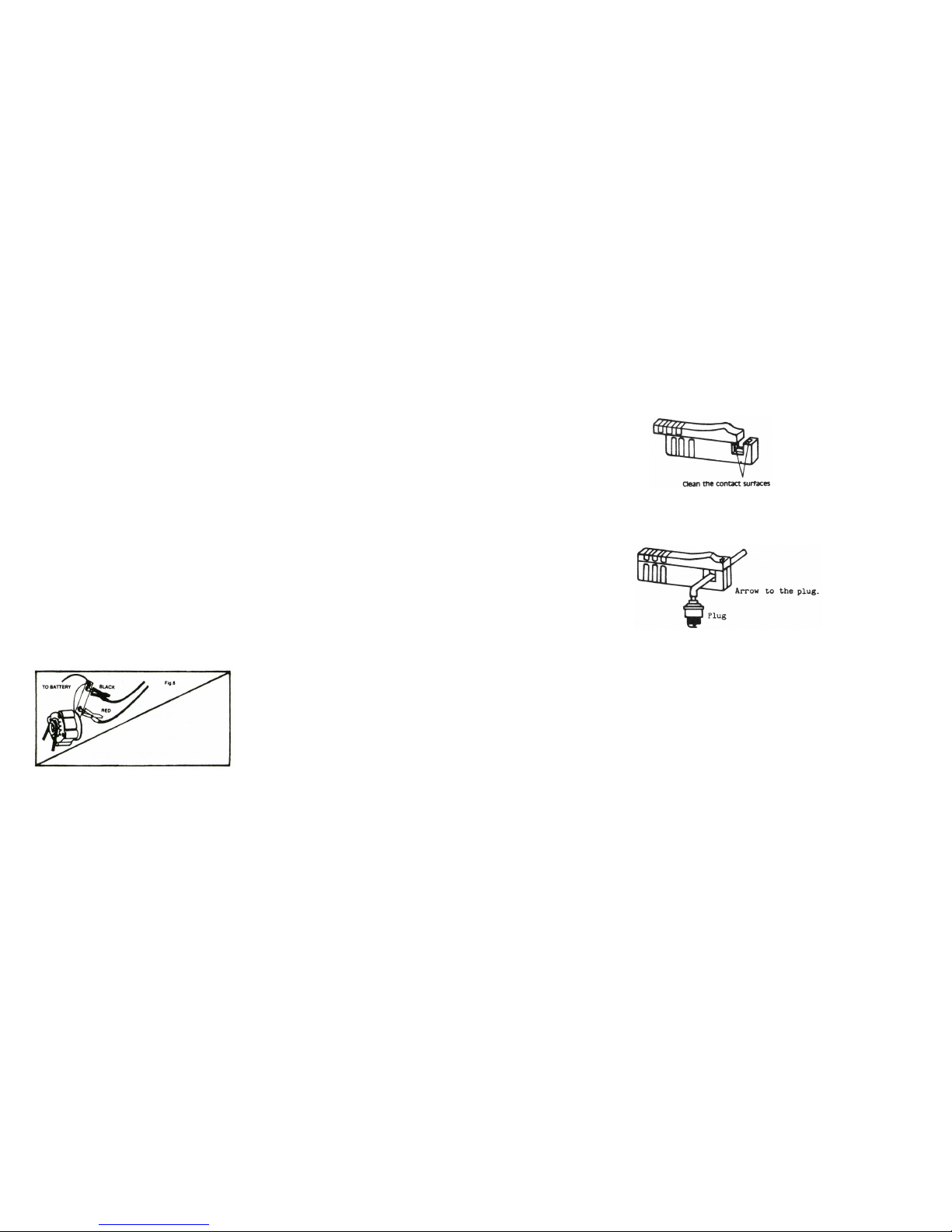
TESTING THE CHARGING CURRENT : (see fig. 6)
1. Disconnect the (-) cable from the battery.
2. Disconnect the wire from the output terminal of the alternator (BAT) and connect the external shunt
between this terminal and the wire just removed.
3. Reconnect the battery cable, crank the engine several times without starting it to partially discharge
the battery.
4. Start the engine, increase the RPM to about 2000 RPM.
Note the reading of the meter.
If it is within 10 AMP of the value specified by the manufacturer. The charging current is OK.
If it is too low proceed to next step to determine if the regulator or the alternator is defective.
5. Refer to steps 2a, b, c of the “testing the charging system” to jump the field terminal of the alternator.
6. Start engine and increase the RPM to 2000 RPM. If the current now is within the value specified, the
regulator is defective; if it is still too low, then the alternator is defective.
POINTS FUNCTION
TESTING THE POINTS RESISTANCE:
1. Connect the black clip to a good electrical ground on the engine. Connect the red clip to the (-)
terminal of the ignition coil.
2. Turn ignition key on; bump the engine until the points are closed.
3 . The pointer of the meter should stay in the OK area, if not the points need to be replaced.
- 5 -
● Connect read clip to battery positive (+) post, black clip to negative (-) post.
● Clip the inductive pick up to any of the spark plug cable, preferably as close as possible of the
spark plug without touching any hot metal part.
NOTE:
If the needle does not move or gives an unstable reading when testing engine RPM, proceed as follow:
1. Check that the jaws of inductive pickup is fully closed and with the right aide facing the spark plug.
2. Check that the contact surfaces of the upper and lower ferrite cores are clean without dirt or grease.
Use a volatile detergent to clean the contact surfaces if necessary.
3. If the needle still fluctuates, slowly move the inductive pickup along the cable towards distributor cap
and observe reading.
4. If needle fluctuation persists, try another spark plug cable. But it is normal for the needle to fluctuate
slightly at low engine speed.
Note:
Now you are ready to read the RPM of the engine regardless of the number of cylinders.
TEST THE AIR/FUEL MIXTURE:
1. Remove the air filter assembly.
2. Using a flat piece of metal, slowly block off the air intake of the carburetor while watching the RPM:
● If the RPM does not change until the intake is almost completely blocked off, the air/fuel mixture is
correct.
● If the RPM increases, the mixture is too lean; if the RPM decreases, the mixture is too rich,
readjust the idle mixture screw accordingly.
TEST THE CONDITION OF THE AIR FILTER:
1. Remove the air filter while watching the RPM, if the RPM varies, the filter is dirty and needs to be
cleaned or replaced.
TEST THE CENTRIFUGAL ADVANCE:
1. Loosen the distributor holdown bolt enough so the distributor can be rotated left and right.
2. Rotate the distributor to get a maximum RPM reading.
3. Increase the RPM to 1000 RPM, again rotate the distributor while watching the RPM; if the RPM can
be increased by 100 or more, the centrifugal advance is faulty, repair or replace as necessary.
TEST THE POSITIVE CRANKCASE VALVE (PCV) :
1. Remove the PCV hose and close off the valve with a finger. Note the RPM, if it drops 50 RPM or
more, the valve is working correctly. If it does not or drops less than 50 RPM, the PCV valve is
plugged or inoperative, repair or replace as necessary.
- 2 -
Page 4
DWELL METER FUNCTION
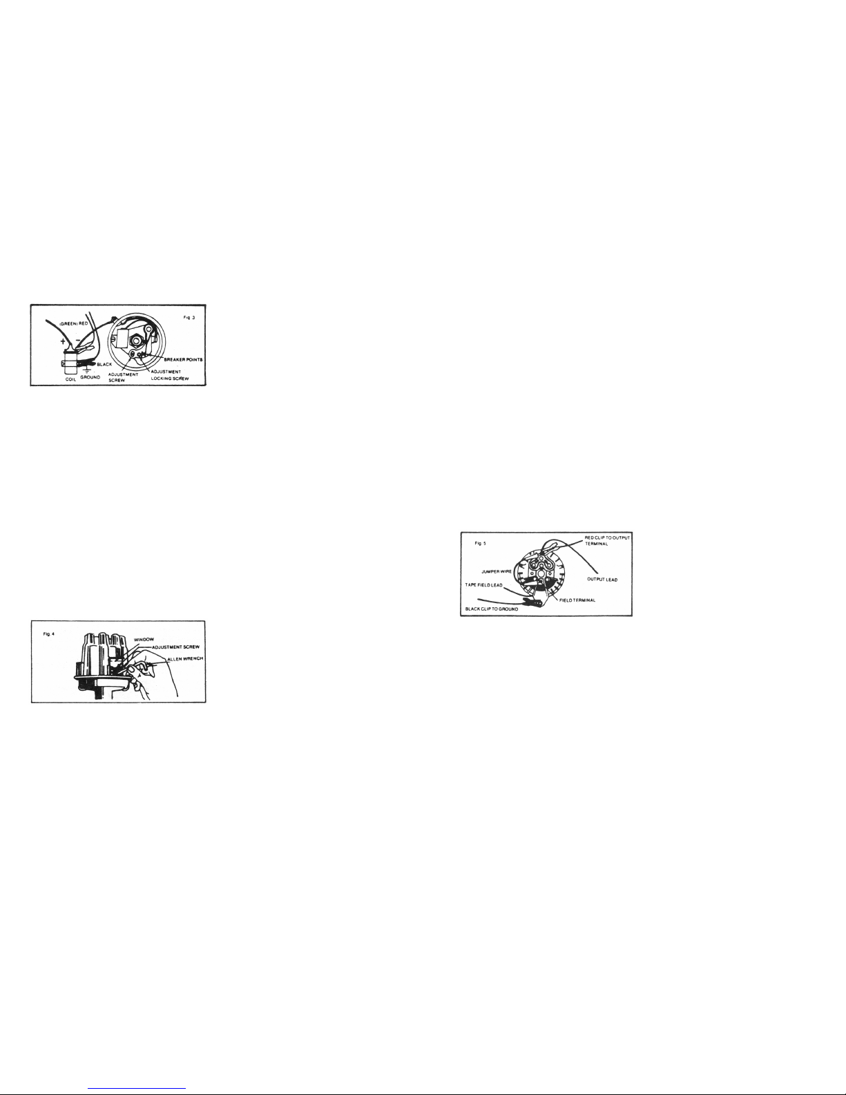
Connecting the analyzer : (see fig. 3)
1. Model equipped with an inductive pick-up:
● The black clip remained connected to the negative (-) terminal of the battery or the part of the
engine relied to the (-) post.
● Move the red clip to the negative (-) terminal of the ignition coil.
Note: The Tachometer still functions while the analyzer is connected as above there might be some slight
oscillations of the pointer at very low RPM reading.
2. Model with only two test leads:
The connections remain identical as in the Tachometer function.
DEFINITION OF DWELL ANGLE:
The dwell angle is the time the points close, allowing the current to go into the ignition coil and build up
energy before the spark.
If the dwell angle is too low, the point gap is too large, resulting in poor acc eleration or missing at high
speed. If the dwell angle is too large, the point gap is too low, resulting in rapid deterioration of the points.
TESTING DISTRIBUTOR CAM WEAR:
1. Note the dwell angle at idle speed.
2. Increase the RPM to about 2000 RPM, while observing the dwell angle, if the dwell angle varies more
than the amount specified by the manufacturer, usually 3, the cam is worn out or the distributor shaft
is bent, repair or replace as necessary.
ADJUSTING THE DWELL ANGLE : (see fig. 4)
Note: On the Delco type distributor, the dwell angle can be adjusted from the outside while the engine is
running. Simply lift the window protecting the Allen screw and use an Allen wrench to adjust the
dwell angle to manufacturer’s specifications.
1. Bring the engine temperature to normal working temperature, stop the engine.
2. Remove the distributor cap and rotor. Ground the high voltage cable from the ignition coil.
3. Loosen the locking screw of the points.
4. Crank the engine while turning the adjusting screw until the proper dwell angle is obtained.
Note: The meter needle may oscillate at cranking speed, use the average reading for measurement.
5. Reassemble the distributor and recheck the dwell at idle speed.
- 3 -
VOLTMETER FUNCTION
TESTING BATTERY LEAKAGE:
1. Connect the black clip to negative (-) post of the battery.
2. Move function switch to Lo-Volt scale.
3. Clip a metal nail to the red clip and touch various spots on the battery while watching the meter, if it
registers any reading, the battery is leaking and need to be cleaned with backing soda and water.
TESTING BATTERY AT HEAVY LOAD:
1. Follow the first two steps of testing battery at light load.
2. Remove the high voltage cable from the ignition coil and ground it.
3. Crank the engine for 15 seconds and note the voltage. If the reading is less than 9.5 on 12 volts
system or 5.7 on 6 volts system check the starter circuit, if it is OK, recharge the battery and retest. If
the reading is low, replace the battery.
TESTING THE CHARGING SYSTEM: (see fig. 5)
1. Connect the meter as in Testing battery at light load.
2. Gradually increase the RPM while watching the meter:
● If the pointer climbs steadily to between 13.5 and 15.5 or to the value specified by the
manufacturer, the charging system-regulator, alternator is OK.
● If the voltage is above the specified value or oscillates erratically, the regulator is defective.
● If the voltage is below the specified value, the regulator or alternator might be defective, proceed
as follow:
a. Disconnect the (-) cable from the battery.
b. Remove the wire from the field terminal of the alternator, do not let it touch the ground.
c. Use a jumper wire, connect the Field terminal of the alternator to its output (BAT) terminal.
Refer to the owner’s manual for more specific information.
d. Reconnect the (-) battery cable, start the engine and slowly increase the RPM while watching
the meter.
● If the voltage is now above 13.5V, the regulator is defective. Caution: perform this test as
quickly as possible and do not exceed 17V.
● If the voltage is still low, the alternator is defective.
- 4 -
 Loading...