

TriQuint Semiconductor Inc TQ9303 Datasheet
T R I Q U I N T S E M I C O N D U C T O R , I N C .
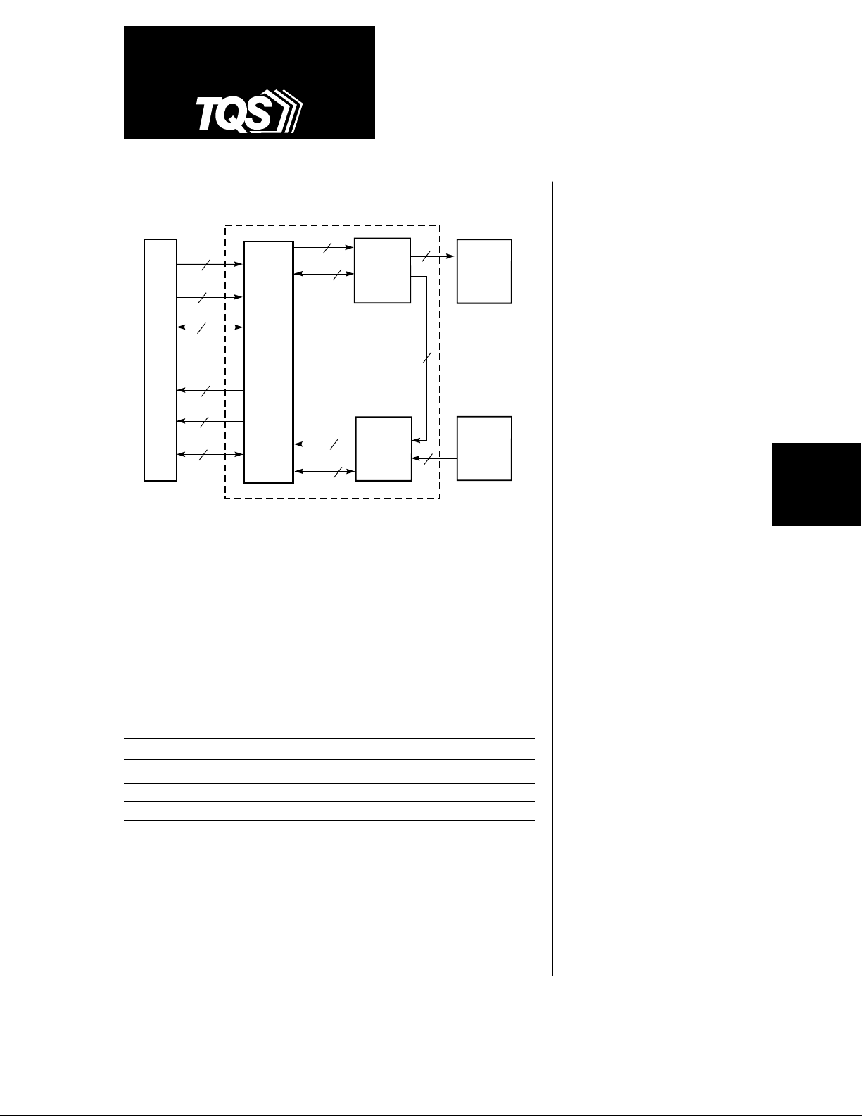
Figure 1. TQ9303 Block Diagram
HOST
Data
Parity
Control
11
Data
Parity
Control
12
Data
32
4
TQ9303
ENDEC
32
4
Control
Data
Control
TQ9501
10
10
or
GA9101
2
Tx
TQ9502
or
GA9102
Rx
2
Optical Tx
2
2
2
or
Copper
Interface
Optical Rx
or
Copper
Interface
The TQ9303 ENDEC (ENcoder/DECoder) implements 8b/10b encoding
and decoding, ordered set encoding and decoding, and parity checking
and generation as defined in the Fibre Channel Physical Signaling
Interface Standard (FC-PH). The ENDEC fully implements the FC-1 layer
of the Fibre Channel Standard. Implemented in a 0.8-micron CMOS
process, the ENDEC also performs 32-bit CRC checking and generation
as defined in the FC-2 layer of the Fibre Channel specification.
TQ9303
Fibre Channel
Encoder/Decoder
Features
• Compliant with ANSI X3T11
Fibre Channel Standard
• Full implementation of
Fibre Channel’s FC-1 layer
• Interfaces directly with
TriQuint’s GA9101/GA9102
and TQ9501/TQ9502 FC-0
Fibre Channel chipsets
• Suitable for proprietary serial
links (virtual ribbon cable)
• Implements 8b/10b encoding
and decoding
• Implements ordered set
encoding and decoding
DATACOM
PRODUCTS
The TQ9303 ENDEC interfaces directly to TriQuint’s FC-0 layer Fibre Channel
Transmitter (Tx) and Receiver (Rx) chipsets at the speeds shown below:
FC Rate Transmitter Receiver Data Rate (Mbaud)
FC-266 GA9101 GA9102 194–266
FC-531 TQ9501 TQ9502 500–625
FC-1063 TQ9501 TQ9502 1000–1250
Triquint’s Transmitter and Receiver devices are designed with TriQuint’s
proprietary 0.7-micron GaAs process. The Tx and Rx interface directly to
copper-based electrical media or to a fiber-optic module. The Transmitter
performs parallel-to-serial conversion on the encoded data and generates
the internal high-speed clock for the serial output data stream. The Receiver
recovers the clock and data from the input serial stream, performs serialto-parallel conversion, and detects and aligns on the K28.5 character.
For additional information and latest specifications, see our website: www.triquint.com
• Checks and generates 32-bit
CRC and parity
•
10-bit TTL-compatible interface
to Transmitter and Receiver
• 32-bit interface to the host
• Fully synchronous operation
• 160-pin PQFP
1
TQ9303
Fibre Channel provides a transport vehicle for Intelligent
Peripheral Interface (IPI) and Small Computer System
Interface (SCSI) upper layer command sets, HighPerformance Parallel Interface (HIPPI) data link layer,
and other user-defined command sets. Fibre Channel
replaces the SCSI, IPI, and HIPPI physical interfaces
with a protocol-efficient alternative that provides
performance improvements over distance and speed.
Fibre Channel is optimized for predictable transfers of
large blocks of data such as those used in file transfers
between processors (such as super computers, mainframes, and super minis), storage systems (such as disk
and tape drives), communications devices, and outputonly devices (such as laser printers and raster scan
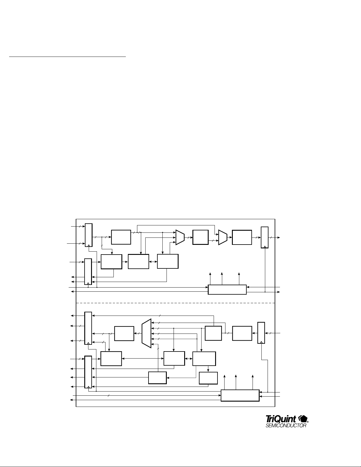
Figure 2. TQ9303 ENDEC Block Diagram
CTXD0..31
CTXC0,
CTXC1,
CTXP0..3,
CTXRAWA,
CTXRAWB
CTXRAW,
CTXPENN,
CTXPMODE
CTXPERR
CTXCERR
CTXCLK
CTXWREF
RESETN
RXERROR
CRXD0..31
CRXP0..3,
CRXS0,
CRXS2..4
RAW Rx,
RXPMODE
CRXS1
CRXS5
WRDSYNC
RXCKPH0,1
CRXCLK
32
17
Shifter
20
Ordered Set
Encoder
32-BIT CRC
Generator/
Checker
40
17
Parity
Checker/
Generator
Word-to-
Half-Word
40
Register
8
3
Register
ENCODER SECTION
DECODER SECTION
1
Mux
20
16
16
1
3
Line State
Decoder
32
Half-Word-
40
36
4
Parity
Generator
2
to-Word
Shifter
Register
8
2
Register
20
graphics terminals). The Fibre Channel protocol is
implemented in hardware, making it simple, efficient,
and robust.
The lower level physical interface is decoupled from the
higher level protocol, allowing Fibre Channel to be configured with various topologies. Point-to-point, multi-drop
bus, ring, and cross-point switch topologies are permitted in Fibre Channel, optimizing it for specific applications.
Fibre Channel supports distances up to 10␣ Km at baud
rates of 132.8125␣ Mbaud to 1.0625␣ Gbaud. Coax and
STP (Shielded Twisted Pair) are used at lower data
rates and shorter distances, while fiber-optic cables are
used for higher data rates and longer distances.
Mux
32-Bit CRC
Checker
17
8b/10b
Encoder
Ordered Set
Decoder
Word Sync
Detector
20
Word
Clk
Clock Generator
10b/8b
Decoder
Mux
Half Word
Clk
20
Word
Clk
Clock Generator
Half-Word-
to-Byte
Shifter
Byte
Clk
Byte-to-
Half-Word
Shifter
Half Word
Clk
10
Byte
Clk
10
Register
10
Register
BTXD0..9
BTXCKIN
BTXCKOUT
BRXD0..9
BRXCLK
BRXSYNC
2
For additional information and latest specifications, see our website: www.triquint.com

Functional Description
TQ9303
The TQ9303 may be divided into two independent
functional sections: the Encoder and Decoder, as
shown in Figure 2. The Encoder section describes the
flow of data from the host to the transmitter.
Conversely, the Decoder section describes the flow of
data from the receiver to the host. Designed for fullduplex operation, the Encoder and Decoder will
transmit and receive one at a time or simultaneously.
The Encoder performs 8b/10b encoding of information
from the host to the transmitter. The Decoder performs
10b/8b decoding of information from the receiver to
the host. The host interface is denoted by a letter C (as
in
CTXP), and the transmit/receive interface is denoted
by a letter B (as in
section are denoted with the letters TX (as in C
and pins within the Decoder section are denoted with
RX (as in C
has a 32-bit transmit data bus and a 32-bit receive data
bus, each with 4-bit parity and 8-bit control. The
transmitter and receiver interfaces to the TQ9303 are
10-bit data buses. Table␣ 5 includes all the pin
descriptions. Detailed descriptions of the Encoder and
Decoder sections follow.
RXS1). At the host interface, the TQ9303
BTXD0). Pins within the Encoder
TXP),
Encoder Section
The Encoder has several functional blocks:
Parity Check, 32-Bit CRC, Ordered Set generator,
8b/10b Encoder, and Clock Generator. The Encoder
section has two modes of operation: Normal mode and
Raw mode. In the Normal mode, the Encoder section
receives a word from the host interface, checks parity,
calculates CRC, divides the word into bytes, encodes
them using 8b/10b, and generates a 10-bit output, as
illustrated in Figure 2. In the Raw mode, the Encoder
section receives a word from the host interface without
parity check, CRC check, or 8b/10b encoding.
The following is the encode sequence data flow:
1. Word input
2. Parity check
3. Word–to–half-word conversion
4. Ordered set encoding
5. 32-bit CRC check or generate
6. Muxing between ordered set, 32-bit CRC, and
unchanged input
7. 8b/10b encoding
8. Muxing between unchanged input and
encoded word
9. Half-word–to–byte conversion
10. Byte output
Parity Check Block
Parity check depends on the TXPENN (Transmit Parity
ENable Not) input. TXPENN high ignores parity, while
TXPENN low checks parity for each byte on the data
bus, CTXD0..31. There are four parity bits (CTXP0..3),
each bit corresponding to a byte of data, as follows:
CTXP0 to CTXD0..7, CTXP1 to CTXD8..15, CTXP2 to
CTXD16..23, and CTXP3 to CTXD24..31. Control bit
TXPMODE (Transmit Parity MODE) alters the normal
meaning of CTXP3. TXPMODE low is the normal mode,
where CTXP3 checks for parity for CTXD24..31. With
TXPMODE high, CTXP3 checks for parity for
CTXD24..31 and CTXC0. CTXC0 is a control input
which indicates whether CTXD0..31 is data or an
ordered set. An ordered set is a Fibre Channel word
where the most significant byte is composed of a valid
special character, K28.5, as defined in the standard.
Appendix A includes a table of valid special characters.
The parity bits follow odd parity convention, where it is
high if the number of ones is even and low if the
number of ones is odd.
DATACOM
PRODUCTS
For additional information and latest specifications, see our website: www.triquint.com
3
TQ9303
CTXPERR (Transmit Parity ERRor) is driven high
when an error is detected in the parity check mode.
When parity checking is disabled, CTXPERR is driven
low. In Raw Mode transmit, where the data
flow
bypasses the parity check, 32-bit CRC, 8b/10b encoder,
and ordered set encoder, CTXPERR is driven low.
32-Bit CRC Block
32-bit Cyclic Redundancy Checking (CRC) generates
or checks CRC, depending on CTXC1. CTXC1 high
generates CRC, while CTXC1 low checks CRC for the
incoming frame. The CRC used in Fibre Channel is the
same as FDDI's frame check sequence, where a 32bit CRC is computed for every frame, starting after
SOF (Start Of Frame) and ending a byte before EOF
(End Of Frame). The resulting 32-bit CRC is
automatically inserted into the frame before EOF.
In the check CRC mode, CTXCERR (Transmit Crc
ERRor) is driven high when a CRC error is detected.
In the generate CRC mode, CTXCERR is driven low. In
Raw Mode transmit where the data flow bypasses the
parity check, 32-bit CRC, 8b/10b encoder, and ordered
set encoder, CTXCERR is driven low.
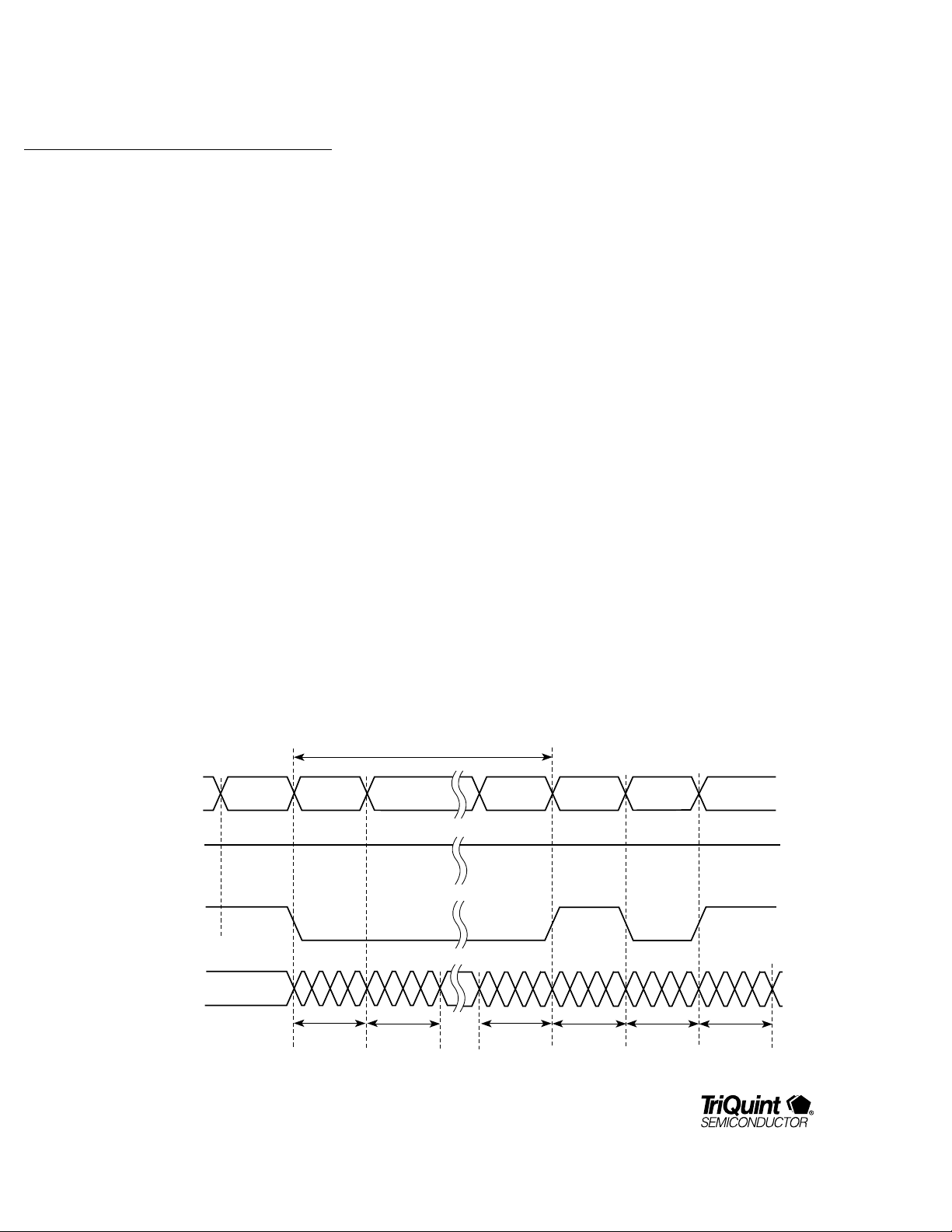
The Generate CRC mode timing diagrams are shown in
Figure 3. CTXC1 is high for the entire frame, when
generating CRC. CTXC0 is high only for the duration of
SOF, indicating that the input word (CTXD0..31) is an
ordered set. Similarly, CTXC0 is high for the duration of
EOF, which is another ordered set. The 32-bit CRC
block computes the CRC for data after SOF and before
EOF. The resulting CRC is inserted between the last
data word and EOF at the output (BTXD0..9).
The Check CRC mode timing diagrams are shown in
Figure 4. CTXC1 is low for the whole frame when
checking CRC. CTXC0 is high only for the duration of
SOF, indicating that the input word (CTXD0..31) is an
ordered set. Similarly, CTXC0 is high for the duration of
EOF, another ordered set. 32-bit CRC begins after SOF
Figure 3. Generate CRC Mode TIming
CTXD0..31
CTXC1
CTXC0
BTXD0..9
4
SOF
For additional information and latest specifications, see our website: www.triquint.com
D0
4 Bytes
SOF
CRC Computation
D1
D0
Dn
Dn-1
EOF
Dn
"d"
CRC
Idle
EOF
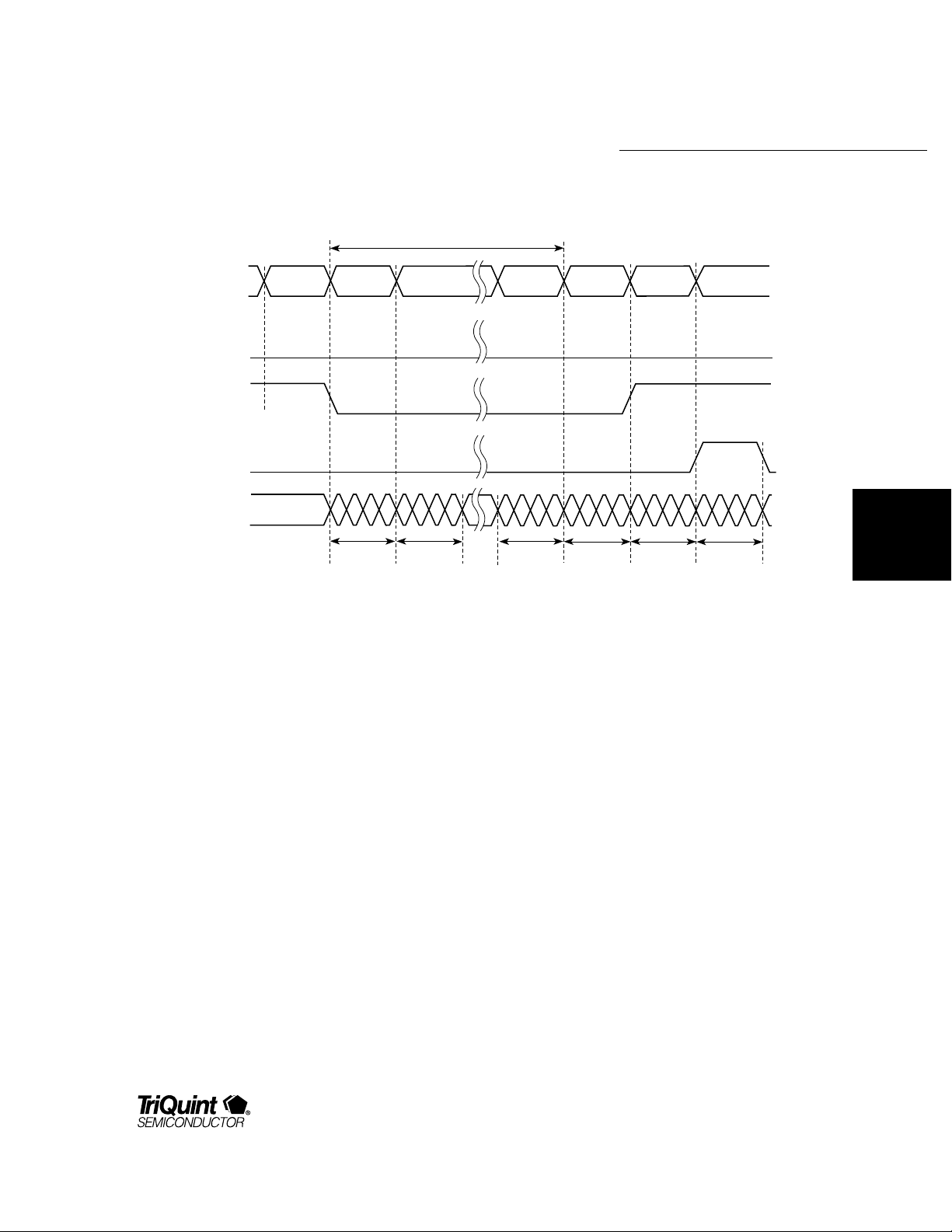
Figure 4. Check CRC Mode TIming
TQ9303
CRC Computation
CTXD0..31
CTXC1
CTXC0
CTCXERR
BTXD0..9
SOF
D0
4 Bytes
SOF
D1
D0
and ends before EOF. CTXCERR remains low if the
computed CRC matches the CRC input on CTXD0..31.
CTXCERR is driven high for one word cycle after the
end of EOF.
If CTXC1␣ is␣ high (generate CRC) then the ENDEC will
add one word (the CRC) to the user’s data frame before
encoding the EOF. In this situation, when the user
commands the ENDEC to encode an EOF, it is latched
for one CTXCLK cycle while the ENDEC inserts the
generated CRC in the data stream. Then the requested
EOF is encoded. During the encoding of the EOF (that
is, the one that was latched for encoding after the CRC
was inserted) the ENDEC ignores the CTX inputs.
Ordered Set Generator Block
An ordered set is a Fibre Channel word in which the
first byte is a K28.5 special character, followed by valid
data characters. Appendix B contains tables for the
ordered set coding scheme. When CTXC0 is high, the
ordered set generator generates an ordered set from
Dn
Dn-1
CRC
Dn
EOF
CRC
Idle
EOF
the most significant byte of the input data, CTXD24..31.
Although only the most significant byte of the input
word is required for generating an ordered set, and
lower order bits CTXD0..23 are “don’t cares” for
encoding the ordered set, parity checking is performed
on the word. Valid word parity must be maintained to
prevent parity errors.
If a parity or CRC error is detected within a frame,
some EOF ordered sets are modified, indicating an
invalid frame. Ordered sets EOF
EOF
(EOF Terminate) are modified to EOFNI (EOF
T
(EOF Normal) and
N
Normal–Invalid).
Any ordered set can be sent or received. If the ordered
set desired is not in the predefined set of Fibre Channel
ordered sets, the user can create it using the “special”
ordered set commands (see Appendix B). For instance,
to send “K28.5, D0.0, D31.7, D0.0,” the user would
send 8500FF00h on CTXD0..31 while holding CTXC0
high. When receiving this same “special” ordered set
DATACOM
PRODUCTS
For additional information and latest specifications, see our website: www.triquint.com
5

TQ9303
(which does not correspond to any predefined Fibre
Channel ordered set) the ENDEC will send the user the
same value, 8500FF00h, while holding CRXS0 high. It
is up the the user to examine the second, third, and
fourth bytes of “special” ordered sets to identify them.
8b/10b Encoder Block
The 8b/10b Encoder encodes 8-bit-wide data to 10-bitwide data to improve its transmission characteristics.
The 8b/10b coding scheme maintains the signal DC
balance by keeping the same number of ones and zeros
for easier receiver designs, provides good transition
density for improved clock recovery, and improves
error checking. It also forces the correct running
disparity when encoding line states, idles, or receiverready ordered sets. Appendix A contains the lookup
tables for the 8b/10b coding scheme.
Clock Generator Block
The Clock Generator generates word, half-word, and
byte clocks required by other blocks in the Encoder. It
uses BTXCKIN (a byte clock) from the transmitter as a
reference clock. For example, using Fibre Channel data
rates, BTXCKIN runs at 106.25␣ MHz using FC1063,
53.125␣ MHz using FC531, and 26.5625␣ MHz using
FC266. The Clock Generator generates BTXCKOUT for
clocking BTXD0..9. It also generates CTXWREF, a word
clock used by the host to generate CTXCLK, which
clocks the host I/O registers.
25.5625␣ MHz using FC1063,
CTXCLK runs at
13.28125␣ MHz using
FC531, and 6.640625␣ MHz using FC266.
Raw Mode Transmit
In Raw Mode Transmit where TXRAW is high for the
whole frame, the input data word bypasses the parity
check, ordered set generator, CRC, and 8b/10b, and is
directly converted to bytes of data. The word-to-byte
mapping of input to output is listed in Table␣ 1. Note that
in raw mode, a “raw” word may be inserted into the
data flow at any time, although running disparity will be
forced negative and the word sync detector state
machine will reset.
Proprietary Link Mode
The PL_IDLE (Proprietary Link IDLE) input can be used
to simplify designs that do not have to conform to Fibre
Channel standards. In such designs the CTXC0 input is
driven low (that is, grounded) and the PL_IDLE pin is
used to distinguish data from nondata. The PL_IDLE
pin controls a bit logic in front of the input registers of
the CTXC0 and CTXD24..31 inputs. It was added to
make it easier for users who aren’t concerned with the
Fibre Channel protocol, but simply want to control the
transmission of data without habing to mux control
information into their data paths in order to control the
CTXD24..31 pins for ordered set control.
On the rising edge of CTXCLK on the first cycle of
PL_IDLE going high, the input registers for CTXC0 and
CTXD24..31 are “jammed” with the value that would
make the ENDEC encode an EOFa. As long as PL_IDLE
is held high, these input registers are jammed with the
value that would make the ENDEC encode an IDLE
ordered set. If CTXC1 is low (check mode) CTXERR will
properly reflect the validity of CRC contained in the
user’s data (assuming the user’s data contains CRC), or
it can be ignored if no CRC is used. If CTXC1 is high
(generate mode), the ENDEC will insert CRC before
encoding the EOFa followed by IDLEs. This creates a
situation in which the user’s data will begin as soon as
PL_IDLE is dropped (with no preceding SOF); but it
does not present a problem for the ENDEC, because the
CRC blocks in both Rx and Tx halves are initialized by
any ordered set. Thus, the IDLE ordered set that
preceeds the user’s data is sufficient to ensure proper
CRC calculation.
6
For additional information and latest specifications, see our website: www.triquint.com

Table 1. Raw Mode I/O Mapping
TQ9303
TRANSMISSION ORDER
FIRST
BYTE
FIRST SERIAL BIT IN TX/RX
SECOND
BYTE
THIRD
BYTE
LAST SERIAL BIT IN TX/RX
FOURTH
BYTE
Bit ENCODE: Word to Bytes DECODE: Bytes to Word
39 CTXC0 BTXD0 BRXD0 CRXS0
38 CTXP3 BTXD1 BRXD1 CRXP3
37 CTXD31 BTXD2 BRXD2 CRXD31
36 CTXD30 BTXD3 BRXD3 CRXD30
35 CTXD29 BTXD4 BRXD4 CRXD29
34 CTXD28 BTXD5 BRXD5 CRXD28
33 CTXD27 BTXD6 BRXD6 CRXD27
32 CTXD26 BTXD7 BRXD7 CRXD26
31 CTXD25 BTXD8 BRXD8 CRXD25
30 CTXD24 BTXD9 BRXD9 CRXD24
29 CTXC1 BTXD0 BRXD0 CRXS2
28 CTXP2 BTXD1 BRXD1 CRXP2
27 CTXD23 BTXD2 BRXD2 CRXD23
26 CTXD22 BTXD3 BRXD3 CRXD22
25 CTXD21 BTXD4 BRXD4 CRXD21
24 CTXD20 BTXD5 BRXD5 CRXD20
23 CTXD19 BTXD6 BRXD6 CRXD19
22 CTXD18 BTXD7 BRXD7 CRXD18
21 CTXD17 BTXD8 BRXD8 CRXD17
20 CTXD16 BTXD9 BRXD9 CRXD16
19 CTXRAWA BTXD0 BRXD0 CRXS3
18 CTXP1 BTXD1 BRXD1 CRXP1
17 CTXD15 BTXD2 BRXD2 CRXD15
16 CTXD14 BTXD3 BRXD3 CRXD14
15 CTXD13 BTXD4 BRXD4 CRXD13
14 CTXD12 BTXD5 BRXD5 CRXD12
13 CTXD11 BTXD6 BRXD6 CRXD11
12 CTXD10 BTXD7 BRXD7 CRXD10
11 CTXD9 BTXD8 BRXD8 CRXD9
10 CTXD8 BTXD9 BRXD9 CRXD8
9 CTXRAWB BTXD0 BRXD0 CRXS4
8 CTXP0 BTXD1 BRXD1 CRXP0
7 CTXD7 BTXD2 BRXD2 CRXD7
6 CTXD6 BTXD3 BRXD3 CRXD6
5 CTXD5 BTXD4 BRXD4 CRXD5
4 CTXD4 BTXD5 BRXD5 CRXD4
3 CTXD3 BTXD6 BRXD6 CRXD3
2 CTXD2 BTXD7 BRXD7 CRXD2
1 CTXD1 BTXD8 BRXD8 CRXD1
0 CTXD0 BTXD9 BRXD9 CRXD0
DATACOM
PRODUCTS
For additional information and latest specifications, see our website: www.triquint.com
7

TQ9303
Proprietary Link Mode (continued)
When PL_IDLE is driven low, data words on CTXD0..31
are encoded just as in Fibre Channel operation. When
PL_IDLE is driven high, the TQ9303 encodes one EOFa
ordered set followed by IDLE ordered sets for as long
as PL_IDLE remains high.
The EOFa ordered set is used to ensure proper running
disparity. When using the PL_IDLE signal, IDLE
ordered sets do not force proper running disparity. It is
therefore necessary to transmit at least one word with
PL_IDLE low followed by at least one word with
PL_IDLE high in order to guarantee proper running
disparity.
Without proper running disparity, the receiver portion
of the TQ9303 may flag the IDLE ordered sets as
errors and prevent the word sync state machine from
reaching the synchronized state as long as the running
disparity is incorrect.
Without proper running disparity, the receiver portion
of the TQ9303 may flag the IDLE ordered sets as errors
and prevent the word sync state machine from
reaching the synchronized state as long as the running
disparity is incorrect.
The contents and parity of CTXD0..31 and CTXP0..3 are
ignored during the word cycles when PL_IDLE is held
high. If CTXC1 is low, then CRC checking will occur,
which may cause the TXCERR signal to indicate an
error, which can be ignored in proprietary designs. If
CTXC1 is driven high, then the TQ9303 will generate a
32-bit CRC word during the first word cycle of PL_IDLE
high. During the second word cycle of PL_IDLE high,
the EOFa will be encoded followed by IDLE ordered
sets. Therefore, at least two word cycles of PL_IDLE
high between data bursts must be provided when using
CRC generation (that is, CTXC1␣ high). When using CRC
generation, the CRXS1 signal is used to indicate CRC
errors. When not using the CRC, CRXS1 should be
ignored. For non-Fibre Channel designs making use of
the PL_IDLE input, the CRXSO output can be used to
distinguish received data from idle time.
Decoder Section
The Decoder has several functional blocks:
10b/8b Decoder, Ordered Set Decoder, Word Sync
Detector, Line State Decoder, 32-bit CRC Checker,
Parity Generator, and Clock Generator.
The Decoder section has two modes of operation: the
Normal mode and Raw mode. In the Normal mode, the
Decoder section takes 10 bits of data from the Receiver
output, decodes it using 10b/8b, decodes ordered sets,
checks CRC, combines four bytes into a single word
output, and generates parity. In the Raw mode, the
Decoder section directly combines the bytes into
words, bypassing 10b/8b decoding, ordered set
decoding, CRC checking, and parity generation.
The following is the decode sequence data flow:
1. Byte Input
2. Byte–to–Half-Word Conversion
3. 10b/8b Decoding
4. Ordered Set Decoding
5. Line State Decoding
6. Word Sync Generation
7. 32-Bit CRC Checking
8. Muxing between Ordered Set, Unchanged Input,
10b/8b Decoded Input, and Status Bits
9. Half-Word–to–Word Conversion
10. Parity Generation
11. Word Output
8
For additional information and latest specifications, see our website: www.triquint.com
 Loading...