

TriQuint Semiconductor Inc TQ5M31 Datasheet
WIRELESS COMMUNICATIONS DIVISION
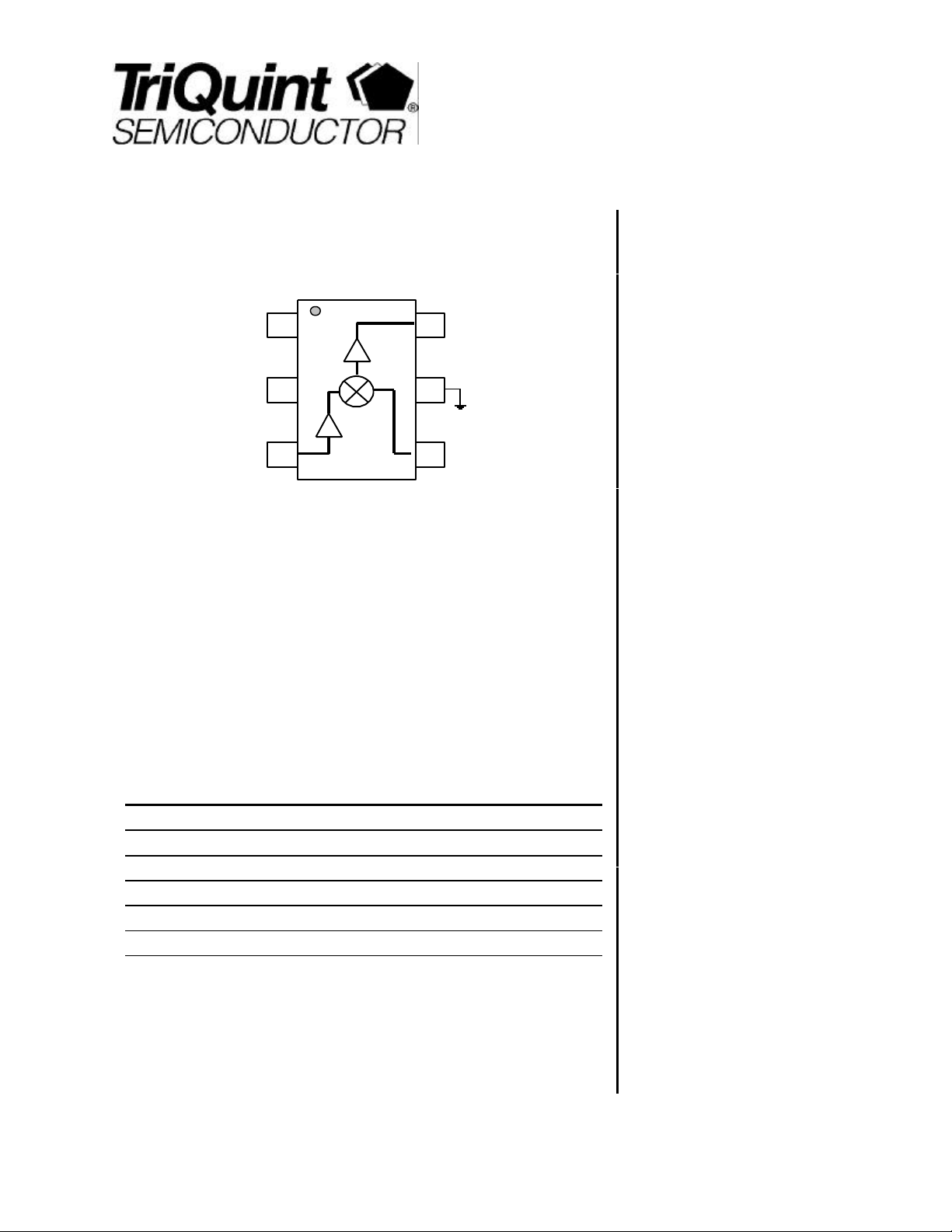
TQ5M31
Vdd
Gain/IP3/current
adjustment
Vdd
GIC
IF
OUT
GND
IF
DATA SHEET
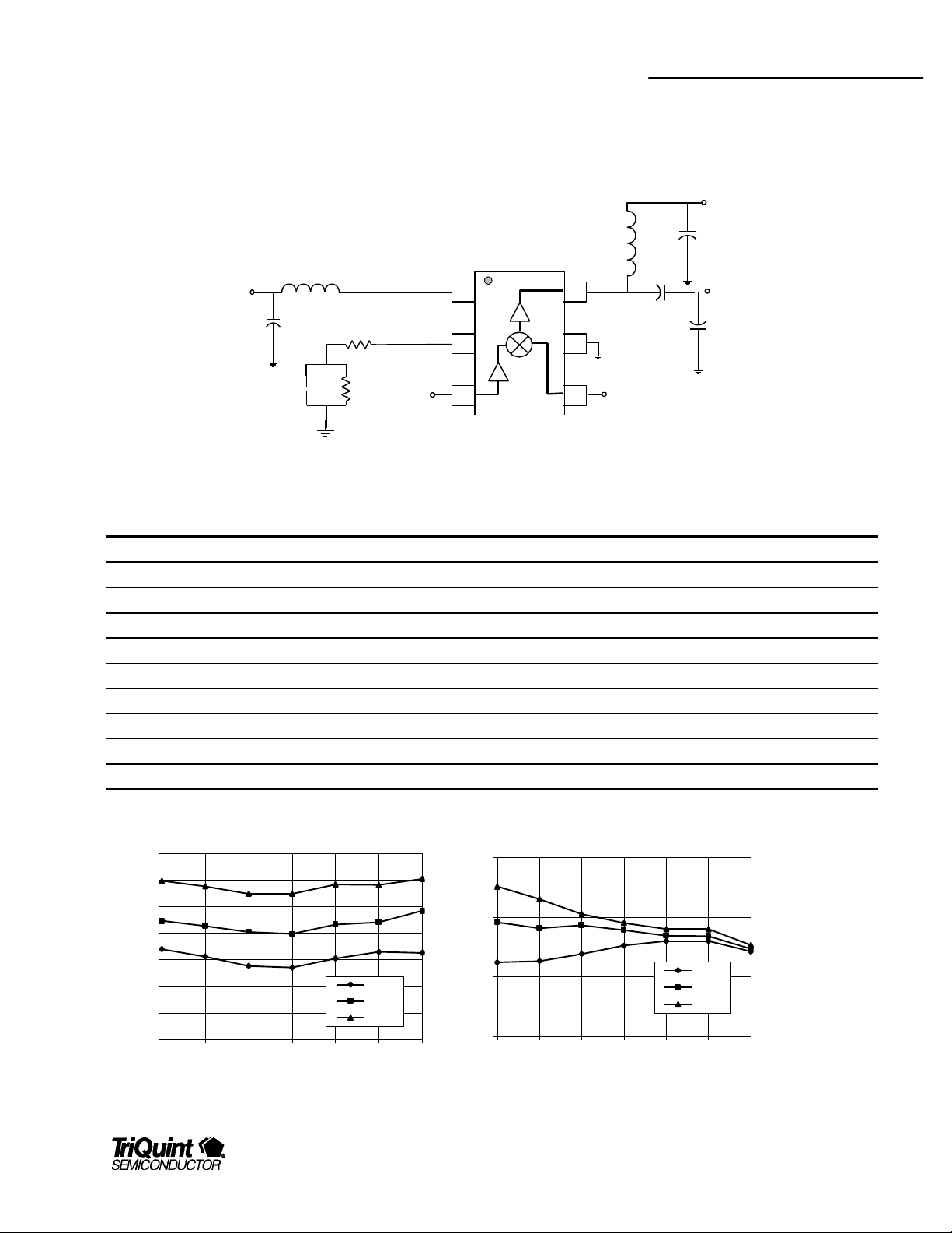
3V Downconverter
Mixer IC
GND
50 ohm
LO INPUT
LO
RF
50 ohm
RF INPUT
Product Description
The TQ5M31 is a general purpose RFIC mixer downconverter designed for multiple
applications including worldwide cellular and PCS mobile phones, ISM bands, GPS
receivers, L band satellite terminals, WLAN and pagers. The TQ5M31 is usable for
applications with an RF frequency range from 500 to 2500 MHz, and an IF output
range from 45 to 500 MHz. The integrated circuit requires minimal off-chip
matching, while allowing for the maximum application flexibility. Low current drain
makes this part ideal for portable, battery operated applications. The output third
order intercept efficiency is very high.
Electrical Specifications
Parameter Min Typ Max Units
RF Frequency 500 2500 MHz
Conversion Gain 4.0 dB
Noise Figure 8.5 dB
Input 3rd Order Intercept 9.0 dBm
DC supply Current 6.2 mA
Note 1: Test Conditions: Vdd=2.8V, Ta=25C, RF=1960MHz, LO=1750MHz, IF=210MHz, LO input=-
4dBm
1
Features
§ Single 3V Operation
§ Adjustable Gain/IP3/Current
§ Low Current Operation
§ Few external components
§ SOT23-6 plastic package
§ High IP3
§ Broadband Performance
Applications
§ Cellular and PCS mobile applications
worldwide
§ Wireless data applications
§ GPS/ISM/ general purpose
For additional information and latest specifications, see our website: www.triquint.com 1
TQ5M31
Data Sheet
Electrical Characteristics
Parameter Conditions Min. Typ/Nom Max. Units
RF Frequency 500 1960 2500 MHz
LO Frequency 600 1750 2700 MHz
IF Frequency 45 210 500 MHz
LO input level -7 -4 0 dBm
Supply voltage 2.7 2.8 4.0 V
Conversion Gain 3.0 4.0 dB
Input 3rd Order Intercept 6.5 9.0 dBm
Supply Current 6.2 8.5 mA
Note 1: Test Conditions (devices screened to the above test conditions): Vdd=2.8V, RF=1960MHz, LO=1750MHz, IF=210MHz, LO input=-4dBm, TC = 25° C, unless
otherwise specified.
Absolute Maximum Ratings
Parameter Value Units
DC Power Supply 5.0 V
Power Dissipation 100 mW
Operating Temperature -40 to 85 C
Storage Temperature -60 to 150 C
Signal level on inputs/outputs +20 dBm
Voltage to any non supply pin +.3 V
2 For additional information and latest specifications, see our website: www.triquint.com
TQ5M31
Data Sheet
Cellular Band Typical Electrical Characteristics
Parameter Conditions Min. Typ/Nom Max. Units
Conversion Gain 3.5 dB
Noise Figure 9.5 dB
Input 3rd Order Intercept 9.0 dBm
Return Loss Mixer RF input
Mixer LO input
Isolation RF to IF; after IF match
LO to IF; after IF match
IF Output Impedance Mixer “On”
Mixer “Off”
Supply Current 4.5 mA
Note 1: Test Conditions: Vdd=2.8V, RF=881MHz, LO=991MHz, IF=85MHz, LO input=-4dBm, TC = 25° C, unless otherwise specified.
10
10
33
40
500
<50
dB
dB
dBm
dBm
Ω
Ω
PCS Band Typical Electrical Characteristics
Parameter Conditions Min. Typ/Nom Max. Units
Conversion Gain 4.0 dB
Noise Figure 9.5 dB
Input 3rd Order Intercept 9.0 dBm
Return Loss Mixer RF input
Mixer LO input
Isolation RF to IF; after IF match
LO to IF; after IF match
IF Output Impedance Mixer “On”
Mixer “Off”
Supply Current 6.0 mA
Note 1: Test Conditions: Vdd=2.8V, RF=1960MHz, LO=1750MHz, IF=210MHz, LO input=-4dBm, TC = 25° C, unless otherwise specified.
10
10
33
40
500
<50
dB
dB
dBm
dBm
Ω
Ω
For additional information and latest specifications, see our website: www.triquint.com 3
TQ5M31
Variable bypass (R4), total resistance
Data Sheet
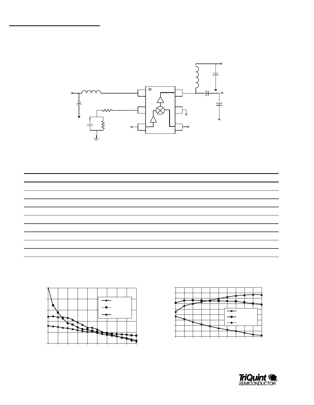
Typical Performance/Applications circuit for GIC tuning plots
Test Conditions (Unless Otherwise Specified): Vdd=2.8V, Ta=25C, RF=1960MHz, LO=1750MHz, IF=210MHz,Current≈6mA, Gain≈4dB, IIP3≈+10dB
Vdd
C2
C3
IF
OUT
C4
Vdd
C1
L1
R3
Vdd
GIC
L2
IF
GND
50 ohm
RF
RF
INPUT
C7
R4
50 ohm LO
INPUT
LO
Bill of Material for TQ5M31 Downconverter Mixer for GIC tuning plots
Component Reference Designator Part Number Value Size Manufacturer
Receiver IC U1 TQ5M31 SOT23-6 TriQuint Semiconductor
Capacitor C1 470pF 0402
Capacitor C2 1000pF 0402
Capacitor C3 22pF 0402
Capacitor C4 27pF 0402
Capacitor C7 150 pF 0402
Inductor L1 2.2nH 0402
Inductor L2 39nH 0402
Resistor R3, R4 Select 0402
25
20
15
10
Performance
5
0
10 30 50 80 110 140 180 220 260 320
4 For additional information and latest specifications, see our website: www.triquint.com
Conversion Gain, Idd and IIP3 Vs Rbias
(Vdd = 2.8v, PLO = - 4dBm)
CG (dB)
Idd (mA)
IIP3 (dBm)
Rbias (ohms)
Performance Vs. Bypass DC Bias Resistance
(RF = 1960 MHz, Vdd = 2.8v, PLO = -4 dBm)
21
18
15
12
9
6
3
Performance
0
-3
-6
100 90 80 70 60 50 40 30 20 10 0
(R3 +R4 = 103 ohm)
Gain (dB)
OIP3 (dBm)
IIP3 (dBm)
TQ5M31
Data Sheet
Cellular Band Typical Performance/Applications circuit
Test Conditions (Unless Otherwise Specified): Vdd=2.8V, Ta=25C, RF=881MHz, LO=966MHz, LO input –4dBm, IF=85MHz,Current≈9mA, Gain≈9dB, IIP3≈+10dB
Vdd
C2
C3
IF
OUT
C4
Vdd
C1
L1
R3
Vdd
GIC
L2
IF
GND
50 ohm
RF
RF
INPUT
C7
R4
50 ohm LO
INPUT
LO
Bill of Material for TQ5M31 Downconverter Mixer Cellular band
Component Reference Designator Part Number Value Size Manufacturer
Receiver IC U1 TQ5M31 SOT23-6 TriQuint Semiconductor
Capacitor C1 1000pF 0402
Capacitor C2 1000pF 0402
Capacitor C3 20pF 0402
Capacitor C4 22pF 0402
Capacitor C7 150pF 0402
Inductor L1 2.2nH 0402
Inductor L2 39nH 0402
Resistor R3 3.3ohm 0402
Resistor R4 39ohm 0402
Noise Figure vs. Temperature vs. Frequency
11
10
12
Input IP3 vs. Temperature vs. Frequency
9
8
7
Noise Figure (dB)
6
5
4
865 870 875 880 885 890 895
Frequency (MHz)
-40 C
+25 C
+85 C
For additional information and latest specifications, see our website: www.triquint.com 5
11
IIP3 (dBm)
10
9
865 870 875 880 885 890 895
Frequency (MHz)
-40 C
+25 C
+85 C
 Loading...