

Page 1

WARRANTY
REGISTRATION:
register online today for a chance
to win a FREE Tripp Lite product—
www.tripplite.com/warranty
U209-004 USB to 4-Port
U209-008 USB to 8-Port
Owner’s Manual
Serial Adapter
Serial Adapter
1111 W. 35th St., Chicago, IL 60609 USA
Customer Support: (773) 869-1234
Copyright © 2006 Tripp Lite. All rights reserved. All trademarks are the sole property of their respective owners.
www.tripplite.com
Page 2

Table of contents
Table of contents ......................................................................................................................................2
Figures ..................................................................................................................................................2
Introduction ..............................................................................................................................................3
System requirements ............................................................................................................................3
Installing the USB-to-Serial Adapter ....................................................................................................3
Installing under Windows XP................................................................................................................3
Installing under Windows 2000.............................................................................................................5
Uninstalling under Windows 2000 or Windows XP ............................................................................7
Making external connections ................................................................................................................7
RS-232 serial connections ....................................................................................................................7
Testing DB-9 serial ports in HyperTerminal ........................................................................................8
Running HyperTerminal ..................................................................................................................8
Using Device Manager ............................................................................................................................8
Accessing Device Manager ..................................................................................................................8
Exploring Device Manager screens ......................................................................................................8
Windows XP and 2000 ....................................................................................................................8
Troubleshooting ......................................................................................................................................11
Appendix A ............................................................................................................................................12
Specifications ................................................................................................................. .....................12
Warranty and Warranty Registration ................................................................................................12
Figures
Figure 1 - Windows XP Found new hardware ..........................................................................................3
Figure 2 - Windows XP Choose your search and installation options ......................................................4
Figure 3 - Windows XP Searches for drivers ............................................................................................4
Figure 4 - Windows XP Wizard installs the software ..............................................................................4
Figure 5 - Windows XP Finished installing ..............................................................................................5
Figure 6 - Windows 2000 Found new hardware........................................................................................5
Figure 7 - Windows 2000 Search for display drivers................................................................................5
Figure 8 - Windows 2000 Locate driver files ..........................................................................................6
Figure 9 - Windows 2000 Finished searching for driver files prompt ......................................................6
Figure 10 - Windows 2000 Finished installing..........................................................................................6
Figure 11 - DB-9 connector pinout ..........................................................................................................7
Figure 12 - Use of DTEs and DCEs in a communication link ................................................................7
Figure 13 - Cabling requirements for RS-232 devices ..............................................................................7
Figure 14 - Windows XP/2000 Device Manager properties, General tab ................................................9
Figure 15 - Windows XP/2000 RS-232 Advanced Options dialog ..........................................................9
Figure 16 - Windows XP/2000 USB serial port, Port settings ................................................................10
Figure 17 - Windows XP/2000 USB serial port, Advanced settings ......................................................10
Figure 18 - Windows XP/2000 USB serial port properties, Driver ........................................................10
Figure 19 - Windows XP/2000 USB serial port, Driver file details........................................................11
2
Page 3

Introduction
This manual describes how to set up and install your USB-to-Serial Adapter.
U209-004 and U209-008 provide four or eight independent RS-232 serial interfaces to the host PC via
the Universal Serial Bus (USB) port.
Each adapter uses high-speed UARTs and deep FIFOs, allowing each channel to obtain data rates up to
921.6 kbps. The adapters are powered over their USB connection (bus-powered), eliminating the need
for an external power supply. The adapters are Plug-and-Play devices and require no hardware
configuration.
Note: These products comply fully with USB Specification version 2.0. They will also operate over slower USB 1.1
connections at a slightly reduced performance level.
System requirements
USB-to-Serial adapters are supported under the Windows 2000/XP (and later) and Linux operating
systems. One USB port is required to connect the adapter to your computer. You can use either a built-in
USB port or an add-in USB host adapter. We recommend the use of a USB 2.0 port for best performance.
Installing the USB-to-Serial Adapter
Caution!
Be sure to allow the installation process to finish without interruption
This section explains how to install the USB-to-Serial adapter under different operating systems. Please
locate and follow the procedure for your computer's operating system.
The USB-to-Serial adapter includes Windows device drivers that enable the serial ports to appear to
Windows as standard COM ports.
Installing under Windows XP
Follow these steps to install the adapter under Windows XP.
1. Turn the power to your computer ON. This
is the system to which the device is to be
connected.
2. Plug the wide flat end of the USB cable into
the downstream connector. This is the
connector located on the back of the computer
or USB hub.
3. Plug the square end of the USB cable into
the USB-to-Serial adapter. Windows tells
you that it has found new hardware and
launches the Found New Hardware Wizard
(figure 1).
Figure 1 - The Found New Hardware Wizard launches
automatically when you first plug in the USB-to-Serial
3
adapter.
Page 4
Installing the USB-to-Serial Adapter
4. Insert the installation CD into the CD-ROM
drive. This is the CD that shipped with the
product.
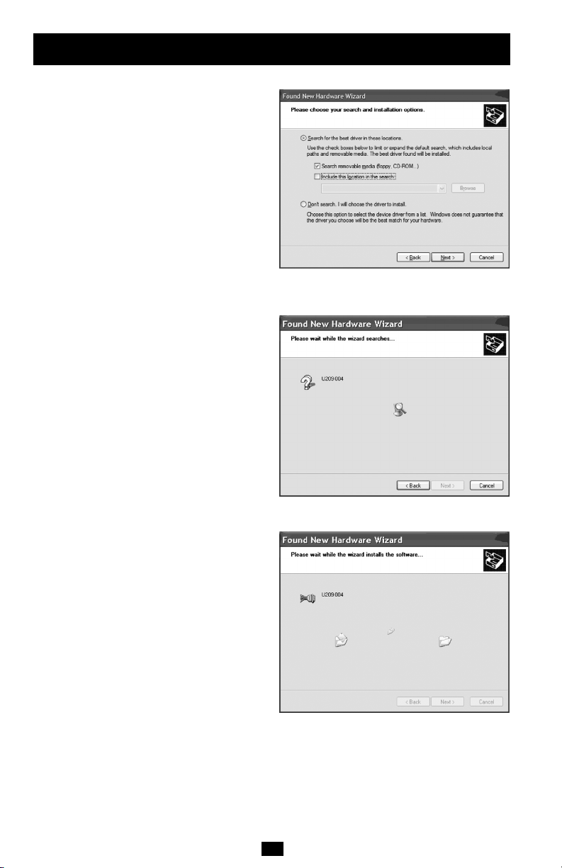
5. Select the "Advanced" option. Click the
Next button. The Choose your search and
installation options prompt displays (figure 2).
6. Select Search removable media (floppy, CD-
ROM). If necessary, you can also select the
Include this location in the search: option and
browse to the location with the USB-to-Serial
drivers. The complete path is
E:\Serial Port Adapters\Drivers\Windows 98,
Me, 2000, XP for USB. Replace E:\ with your
CD-ROM designation.
7. Click the Next button. Windows searches for
drivers for the adapter (figure 3).
8. The Wizard locates and starts to install the
necessary software. The Wizard installs the
software (figure 4), followed by the Finished
installing prompt (figure 5).
Figure 2 - Windows XP Choose your search and
installation options prompt.
(continued)
Figure 3 - Windows XP Searches for drivers prompt.
Figure 4 - Windows XP Wizard installs the software.
4
Page 5

Installing the USB-to-Serial Adapter
9. Press the Finish button to continue. The
USB adapter installation is complete.
Figure 5 - Windows XP Finished installing prompt
indicates that the adapter has been successfully
Installing under Windows 2000
Follow these steps to install the USB-to-Serial
adapter under Windows 2000.
1. Turn on the power to your computer
system. This is the system in which the device
is to be installed.
2. Plug the wide flat end of the USB cable into
the downstream connector. This is the
connector located on the back of the computer
or USB hub.
3. Plug the square end of the USB cable into
the back of the USB-to-Serial adapter.
Windows tells you that it has found new
hardware and launches the Add New Hardware
Wizard. The Found new hardware prompt
displays (figure 6).
4. Click the Next button. The Search for display
drivers prompt displays (figure 7).
Figure 6 - Windows 2000 found new hardware prompt.
(continued)
installed.
Figure 7 - Windows 2000 search for display drivers
5
prompt.
Page 6

Installing the USB-to-Serial Adapter
5. Insert the installation CD into your CD-
ROM drive. This is the CD that shipped with
the adapter.
6. Select Search for a suitable driver for my
device (recommended).
7. Click the Next button. The Locate driver files
prompt displays (figure 8).
8 Select CD-ROM drives. You can also choose
to specify a location and browse to the desired
location with the USB-to-Serial drivers. The
complete path is E:\Serial Port dapters\Drivers\
Windows 98, Me, 2000, XP for USB. Replace
E:\ with your CD-ROM drive designation.
9 Click the Next button. Windows searches for
drivers for the adapter. The Finished searching
for driver files prompt displays (figure 9).
10. Click the Next Button.
11. The wizard Proceeds with the Installation.
The Please Wait while the Wizard Installs the
Software screen displays, followed the
Finished Installing prompt (figure 10).
12. Press the Finish button to continue. The
USB-to-Serial adapter installation is complete.
Figure 8 - Windows 2000 Locate driver files prompt.
(continued)
Figure 9 - Finished searching for driver files.
Figure 10 - Windows 2000 Finished installing prompt
indicates that the adapter has been successfully
6
installed.
Page 7

Installing the USB-to-Serial Adapter
(continued)
Uninstalling under Windows 2000 or Windows XP
Follow these steps in the event that you need to uninstall or reinstall the USB-to-Serial software.
1. From the Control Panel, select System.
2. Press the Hardware tab.
3. Click on Device Manager.
4. Scroll down to Multi-port serial adapters and expand.
5. Highlight your USB-to-Serial adapter; for example, U209-004 or U209-008
6. Select the Action menu option.
7. Select Uninstall from the drop down menu.
8. Click OK at the Confirmation screen. Note that this also removes all the serial ports associated with
your USB-to-Serial adapter.
Making external connections
RS-232 Serial Connections
RS-232 devices are classified by their function as
either Data Terminal Equipment (DTE) or Data
Communication Equipment (DCE).
Note: A DTE device is the communication source. A
DCE device provides a communication channel between
two DTE-type devices.
USB-to-Serial adapters are DTE devices that
connect to peripheral equipment through a male
DB-9 connector. The following table lists the serial
port connector definitions.
Figure 11 - DB9 connector pinout.
RS-232 signal description DB-9
Data Carrier Detect (DCD) 1
Receive Data (RxD) 2
Transmit Data (TxD) 3
Data Terminal Ready (DTR) 4
Signal Ground (GND) 5
Data Set Ready (DSR) 6
Request To Send (RTS) 7
Clear To Send (CTS) 8
Ring Indicator (RI) 9
DTE- and DCE-type devices have complementary
pinouts that allow terminals and modems to
connect directly using a one-to-one cable as shown
in Figure 13. Two DTE-type devices can be
connected by a null modem cable. A typical null
modem cable is also shown in the figure.
Note: In many applications, DCEs are unnecessary.
This allows you to use a null modem cable (modem
eliminator cable) to directly connect two DTE type
devices.
Figure 12 - Use of DTEs and DCEs in a
communication link.
Cabling requirements for RS-232C devices
Figure 13 - illustrates the RS232 pinouts for typical
DTE- to-DCE and DTE-to-DTE cables with 9-pin
connectors.
7
Page 8

Making external connections
(continued)
Testing DB-9 serial ports in HyperTerminal
This section explains how to test the functionality of your USB-to-Serial adapter using HyperTerminal.
An RS-232 loopback connector is included with the USB-to-Serial adapter.
Running HyperTerminal
1. Attach the loopback connector to the DB-9 Connector.
2. Launch HyperTerminal. From the Windows Start Menu, select Programs > Accessories>
Communications > HyperTerminal.
3. Create a new session. When prompted, give the session any name you wish.
4. Select the COM # associated with port 1 from the dropdown list. You are now set up to test the
first serial port. Note: Leave all settings at default.
5. With the session open, type any text. If the text you type is echoed on the screen, the port is
functioning properly.
6. Close the session.
7. Repeat steps 3 through 6 for each serial port. If the text you type is echoed on the screen, the port
is functioning properly.
Using Device Manager
This section explains how to use Device Manager to view the properties of the serial ports enumerated
by the USB-to-Serial adapter.
Accessing Device Manager
1. Select Start > Settings > Control Panel.
2. Double click the System icon. The System Properties dialog box opens. (Note: If you do not see
the System icon, you may need to switch to “Classic View”.)
3. Click the Hardware tab, and then press Device Manager. Device Manager lists all the hardware
devices that are registered inside the Windows registry.
Exploring Device Manager Screens
Windows XP and 2000
Device Manager provides two property dialogs that apply to the USB-to-Serial adapter.
• Ports (COM & LPT) device group property box
• Multi-port serial adapters device group property box
Use the Ports (COM & LPT) device group property box to view and set the port settings and to view
device usage and driver information for the serial ports. Use the Multi-port serial adapter's device group
property box to view and set the advanced options and to view device usage and driver information for
the USB-to-Serial adapter.
8
Page 9

Using Device Manager
1. With Device Manager open, expand the
Multi-port serial adapters device group.
Your USB-to-Serial adapter should appear in
the list.
2. Double click the USB-to-Serial adapter.
The Properties dialog box opens and displays
the General tab (figure 14).
3. Click the USB Serial Ports Advanced
Options tab to view the port setting
properties. The Advanced Options dialog box
displays (figure 15).
4. The RS-232 USB Serial Port Advanced
Options dialog box displays the firmware
revision of the USB-to-Serial adapter.
There are no user-configurable settings for RS232 only USB-to-Serial adapters.
5. Click Cancel to close the property box.
6. With Device Manager open, expand the
Ports (COM & LPT) device group. The ports
associated with the USB-to-Serial adapter
should appear in the list of ports
7. Double click the desired port. The USB
Serial Port Properties dialog box opens and
displays the General tab
(continued)
Figure 14 - Windows XP/2000 Device Manager
properties, General tab.
Figure 15 - The Advanced Options dialog box.
9
Page 10

Using Device Manager
8. Click the Port settings tab. The Port Settings
dialog box displays (figure 16).
9. This Port Settings tab allows you to set
default values for the following:
• Bits per second
• Data bits
• Parity
• Stop bits
• Flow control
Most applications do not make use of these
default settings, but prefer to make their own
settings. See the Setting advanced options
section for details.
10 . Press the Advanced button. The Advanced
Options dialog box opens (figure 17).
11. Use the dropdown box to select the port
whose settings you wish to change. Click
Cancel to return to the Port Settings tab.
12 . Click the Driver tab to view the driver
information and update the driver. The USB
Serial Driver properties dialog box displays
(figure 18).
13. You have several options:
• View detailed driver information
• Update the device drivers
• Uninstall your USB-to-Serial adapter*
• Return to the previously installed driver.
(XP only)
• Save your changes and exit
• Abandon your changes and return to the
Device Manager
* Uninstall the entire device instead by using
the Driver dialog for the multiport serial
adapter.
(continued)
Figure 16 - USB Ports Settings box, which lets you set
the default port settings, view the advanced options, and
restore the default settings.
Figure 17 - Windows XP/2000 USB serial port,
Advanced settings box.
Figure 18 - Windows XP/2000 USB serial port
properties, Driver box.
10
Page 11

Using Device Manager
14 . Click the Driver Details button to view
detailed driver information. The Driver File
Details dialog box opens (figure 19).
15 . Driver File Details dialog box displays the
following information:
• Provider
• File version
• Copyright
• Digital Signer (Windows XP only)
This is the version of the installed software
Indicates whether Microsoft has approved this
version.
16. Click Cancel to close the dialog.
(continued)
Figure 19 - Windows XP/2000 USB serial port, Driver
file details box.
Troubleshooting
This section lists some common problems and their causes. If the information below does not provide a
solution, then contact technical support.
Note: Any unauthorized repairs or modifications will void the adapter's warranty.
Problem Cause Solution
The USB-to-Serial The cables are not 1. Check all cables to make sure that they are
adapter cannot connected correctly. connected correctly.
communicate with other 2. Make sure that each cable is securely
equipment. attached.
The device driver is 1. Double check the Device Manager per the
not installed. instructions in Using Device Manager to
The USB port is faulty. If possible, connect a known good USB device
ensure that drivers are installed correctly and
that all devices are working properly.
2. Try uninstalling the USB adapter from the
Device Manager window and then repeat the
hardware installation instructions.
to the PC or hub connector and see if it
operates properly.
11
Page 12

Appendix A
Specifications
Bus interface USB Specification 2.0, high speed 480 Mbps. Backward compatible
Baud rates Up to 921,600 bps. Factors impacting performance include:
Ports U209-004: 4
UARTs Custom high-speed UARTs with 1024-byte FIFOs for both transmit and
Transceivers RS-232 Output: Voltage Swing: +/-5V min, +/-5.4V typical
Connectors DB-9 Male
Dimensions 9.18" L x 5.25" W x 2.363" H
Power Requirements USB bus powered (no external power connection required)
Temperature: Operating: 0° to 70° C Storage: -50° to 80° C
Humidity 10 to 90%
OS Support Windows 2000, Windows XP
with USB 1.1 full speed 12 Mbps.
• Hardware flow control
• Horsepower of the host computer
• Quality of and length of cables
• Continuous or "bursty" data
U209-008: 8
receive. Automatic hardware and software flow control.
RS-232 Input: Voltage Range: -15V min, +15V max; Input Threshold Low:
0.6V min, 1.0V typical; Input Threshold High: 2.4V max, 1.5V typical
Suspend Power: < 500 uA
Unconfigured Power: < 100 mA
Configured Power: < 500 mA
Warranty and Warranty Registration
5-YEAR LIMITED WARRANTY
TRIPP LITE warrants its products to be free from defects in materials and workmanship for a period of five (5) years from the
date of initial purchase. TRIPP LITE.s obligation under this warranty is limited to repairing or replacing (at its sole option) any
such defective products. To obtain service under this warranty, you must obtain a Returned Material Authorization (RMA)
number from TRIPP LITE or an authorized TRIPP LITE service center. Products must be returned to TRIPP LITE or an
authorized TRIPP LITE service center with transportation charges prepaid and must be accompanied by a brief description of
the problem encountered and proof of date and place of purchase. This warranty does not apply to equipment that has been
damaged by accident, negligence or misapplication or has been altered or modified in any way.
EXCEPT AS PROVIDED HEREIN, TRIPP LITE MAKES NO WARRANTIES, EXPRESS OR IMPLIED, INCLUDING
WARRANTIES OF MERCHANTABILITY AND FITNESS FOR A PARTICULAR PURPOSE.Some states do not permit limitation
or exclusion of implied warranties; therefore, the aforesaid limitation(s) or exclusion(s) may not apply to the purchaser.
EXCEPT AS PROVIDED ABOVE, IN NO EVENT WILL TRIPP LITE BE LIABLE FOR DIRECT, INDIRECT, SPECIAL,
INCIDENTAL OR CONSEQUENTIAL DAMAGES ARISING OUT OF THE USE OF THIS PRODUCT, EVEN IF ADVISED OF
THE POSSIBILITY OF SUCH DAMAGE. Specifically, TRIPP LITE is not liable for any costs, such as lost profits or revenue, loss
of equipment, loss of use of equipment, loss of software, loss of data, costs of substitutes, claims by third parties, or otherwise.
WARRANTY REGISTRATION
Visit www.tripplite.com/warranty today to register the warranty for your new Tripp Lite product. You'll be automatically entered
into a drawing for a chance to win a FREE Tripp Lite product!*
* No purchase necessary. Void where prohibited. Some restrictions apply. See website for details.
Tripp Lite follows a policy of continuous improvement. Product specifications are subject to change without notice.
12
200612037 93-2646
 Loading...