

Page 1
Owner’s Manual
1111 W. 35th Street • Chicago, IL 60609 USA
(773) 869-1234 • www.tripplite.com
Copyright ©2007 Tripp Lite. All rights reserved.
SmartOnline™ is a trademark of Tripp Lite.
Internal Battery Packs
For use with Tripp Lite SmartOnline™3-Phase
UPS Systems that accept internal battery pack connection.
Model #: SURBC2030
Warranty
Registration:
register online today for a chance
to win a FREE Tripp Lite product—
www.tripplite.com/warranty
Important Safety Warnings
Adding or Replacing Internal Batteries
Warranty & Warranty Registration
1
2
5
Español
6
Français
11
Important Safety Warnings
SAVE THESE INSTRUCTIONS! This owner's manual contains important instructions and warnings that must be followed during the installation and
operation of SURBC2030 Internal Battery Packs. The owner's manuals included with compatible products (UPS systems and battery module
compartments) include additional safety instructions that must be followed during installation and operation. Failure to heed these instructions may
cause permanent damage to the UPS system (voiding its warranty) and create a potential for serious personal injury or death from lethal high voltage.
• Do not use Tripp Lite UPS Systems or Internal Battery Packs in life support applications in which a malfunction or failure of a Tripp Lite UPS
System or Internal Battery Pack could cause failure or significantly alter the performance of a life support device.
• The UPS system contains its own energy source (battery). The output terminals may be live even when the UPS is not connected to an AC supply.
• Your UPS does not require routine maintenance. Do not open the UPS's power module for any reason; there are no user-serviceable parts inside.
Because of the risk of electrical shock, only qualified electricians should open the battery module.
• Because the batteries present a risk of electrical shock and burn from high short-circuit current, batteries should be changed only by trained service
personnel observing proper precautions. Remove watches, rings, and other metal objects. Use tools with insulated handles. Wear rubber gloves and
boots. Do not lay tools or metal parts on top of the batteries. Do not short or bridge the battery terminals with any object.
• Do not dispose of the batteries in a fire. The UPS batteries are recyclable. Refer to local codes for disposal requirements, or in the USA only, refer to
these sources for recycling information: 1-800-SAV-LEAD (1-800-728-5323), 1-800-8-BATTERY (1-800-8-228-8379), or www.rbrc.com.
• Internal batteries must be replaced by equivalent batteries available from Tripp Lite.
• Do not operate your UPS without batteries.
• Battery fuses should be replaced only by factory authorized personnel. Blown fuses should be replaced only with fuses of the same number and type.
• Potentially lethal voltages exist within this unit as long as the battery supply is connected. Service and repair should be done only by trained
personnel. During any service work, the UPS should be turned off or put into manual bypass.
• Do not connect or disconnect the battery modules while the UPS is operating from the battery supply or when the unit is not in bypass mode.
1
Page 2
2
Adding or Replacing Internal Batteries
DANGER!
POTENTIALLY LETHAL HIGH VOLTAGE! FOR QUALIFIED ELECTRICIANS ONLY!
Follow all safety precautions in the Safety section before adding or replacing internal batteries.
DANGER!
DO NOT REMOVE BATTERY SLEEVE!
Do not remove the plastic sleeve covering the battery strings.The sleeve is designed to prevent accidental contact with the
terminals on the individual batteries. Contact with the terminals will create a potential for serious injury or death from lethal
high voltage. Do not allow tools or other metal objects to come in contact with the terminals.
CAUTION!
BATTERY PACKS ARE HEAVY!
Use assistants as needed.
WARNING!
CHECK BATTERY PACK VOLTAGE BEFORE COMPLETING INSTALLATION
Do not install battery packs with DC voltages outside the acceptable range. (They may compromise battery backup
capabilities).
NOTE!
Each battery pack consists of two strings of batteries: one string with a BLACK cable and one string with a RED cable.
The batteries are designed for hot-swap replacement, which
allows connected equipment to continually receive AC mains
power (but not battery backup support in the event of a
blackout) during the battery installation procedure. See
“Operation of Manual Bypass Switch” in the Operation section
of the UPS System’s owner’s manual. Although the batteries
can be hot-swapped, qualified service personnel may want to
completely turn the UPS off during battery installation. See
“Turning the UPS Off” in the Operation section of the UPS
System’s owner’s manual.
Internal battery packs must be replaced by equivalent batteries
available from Tripp Lite. Adding battery packs will increase
recharge time. Individual models may vary slightly from
diagrams.
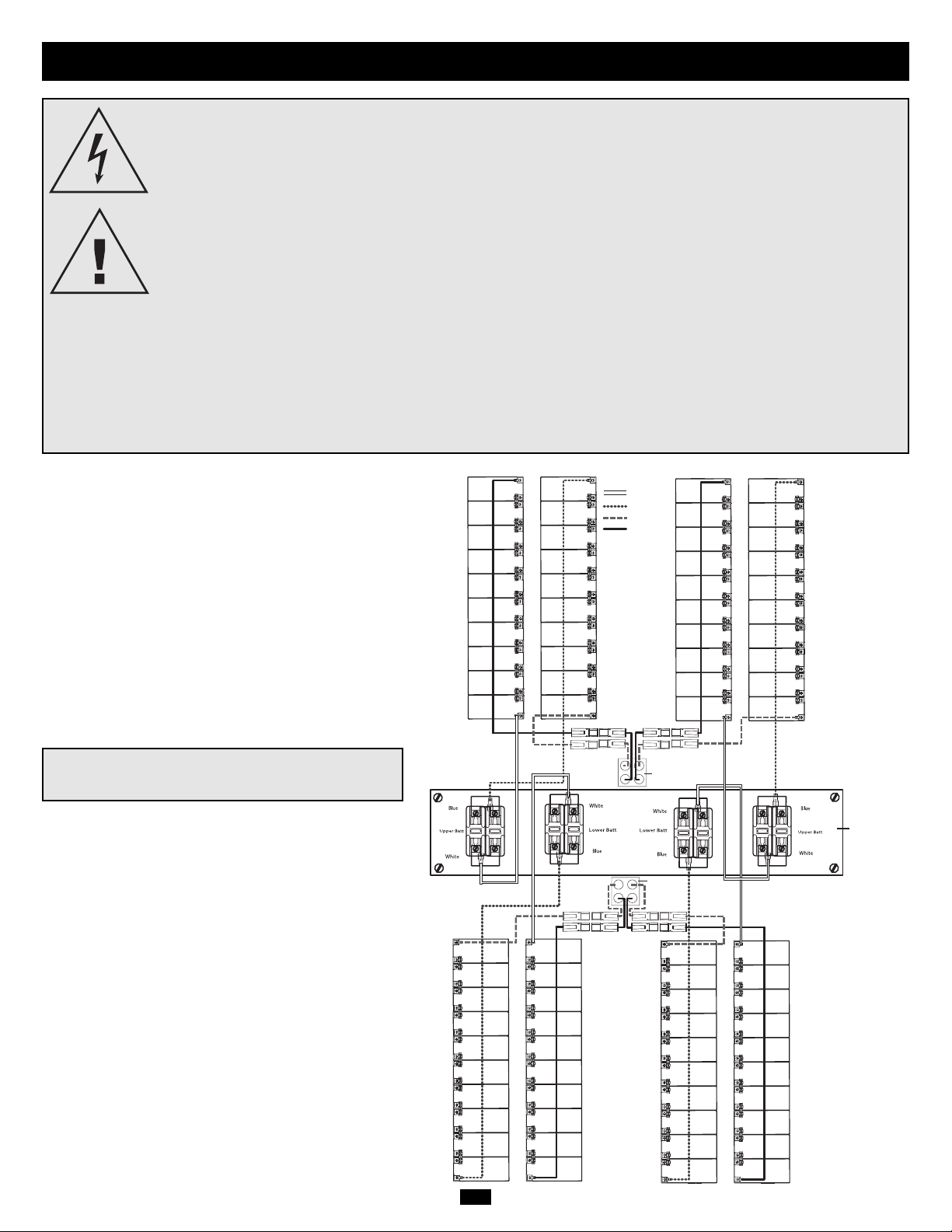
INTERNAL BATTERY PACK WIRING
DIAGRAM
Qualified service personnel should familiarize themselves with
the battery pack wiring diagram prior to adding or replacing
batteries. The battery module can accept up to four battery
packs (each pack consisting of two strings). The diagram
shows all four battery packs connected for illustrative
purposes only. The actual number of batteries shipped with the
UPS System varies depending on model number.
White wire
Blue wire
Red wire (+)
Black wire (–)
UPS System
Battery Back
Connector
UPS System
Battery Back
Connector
Fuse Block Bracket
Page 3
3
Adding or Replacing Internal Batteries
(continued)
Place the UPS System in Bypass Mode or completely turn it off,
depending on preference. See “Operation of Manual Bypass Switch”
or “Turning the UPS Off” in the Operation section of the UPS
System’s owner’s manual.
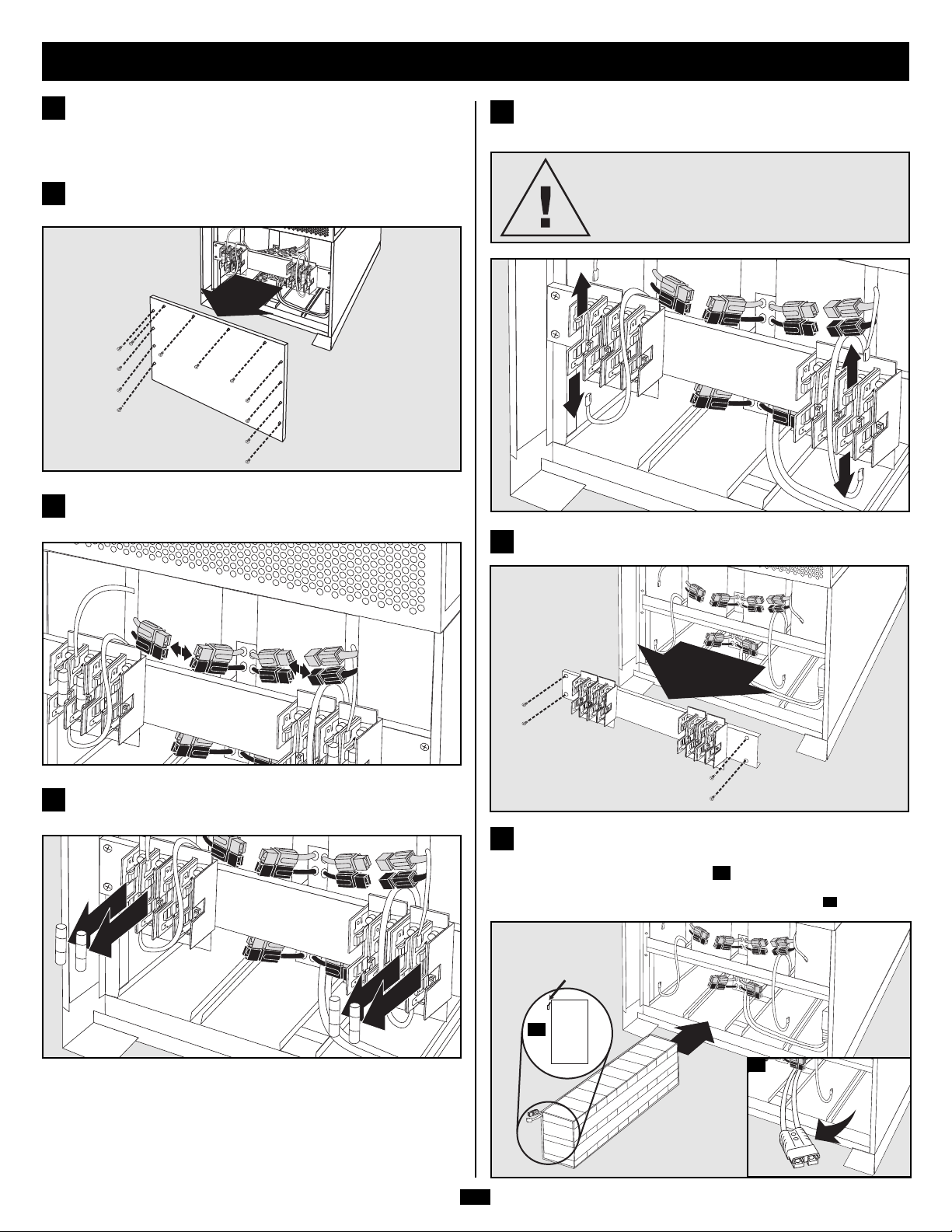
1
Remove battery access panel, located on the FRONT of the UPS
system.
2
Disconnect the RED and BLACK cables attached to each internal
battery pack.
3
Remove the battery cartridge fuses from each fuse block.
Save the fuses.
4
Disconnect the BLUE and WHITE jumper cables attached to each
fuse block.
5
CAUTION!
When disconnecting the jumper cables, pull
them straight away from the fuse block with even
force. Do not wiggle them side-to-side, as this
may damage the connector.
Remove the fuse block bracket.
6
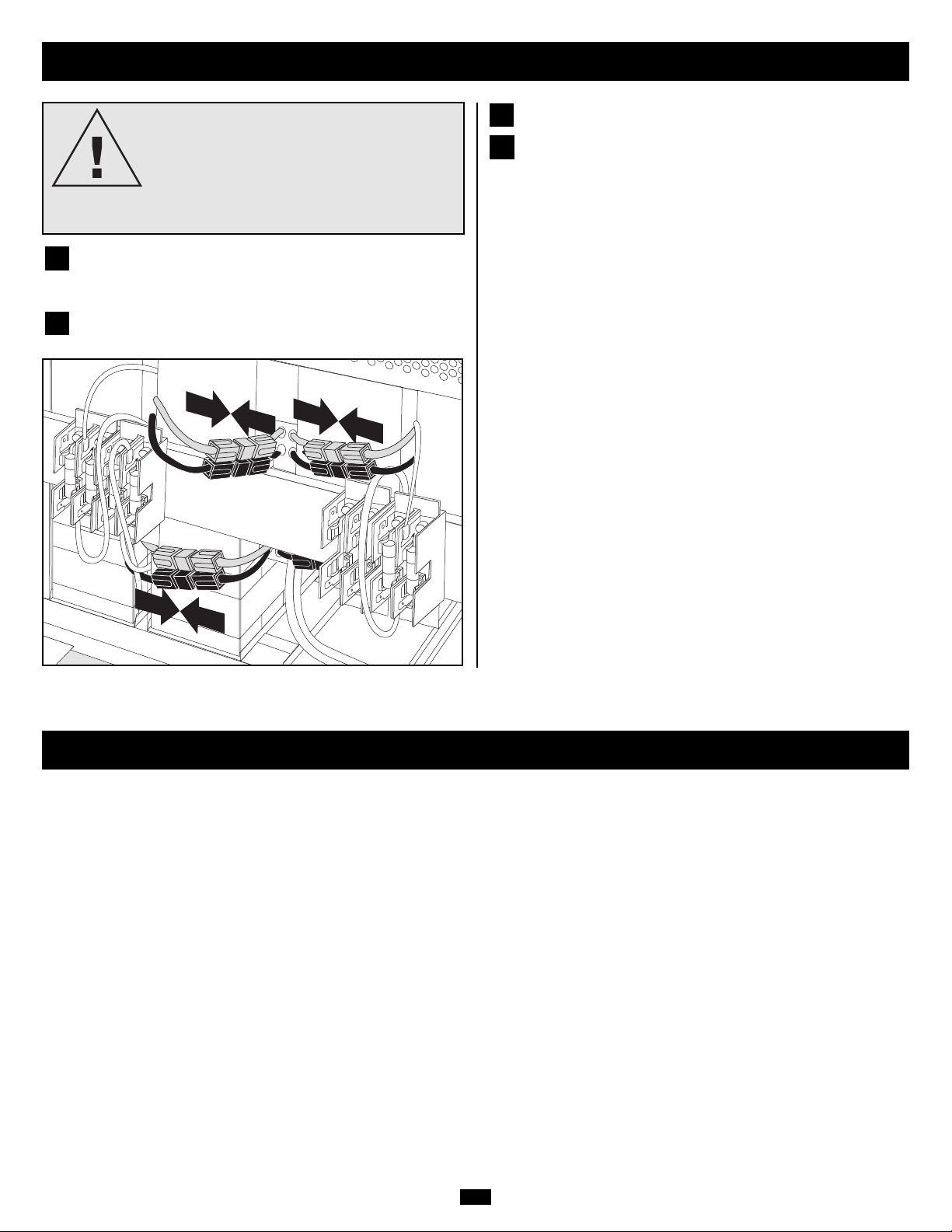
Slide the battery string with the RED cable into an empty slot within
the battery compartment as shown. Make sure that the string is
oriented as shown in the diagram .
NOTE: If the auxiliary battery connector is in the way, remove its mounting screw and
position the cable to allow adequate room to add the battery strings .
7B
7A
7
7A
7B
TERMINALS
Page 4
4
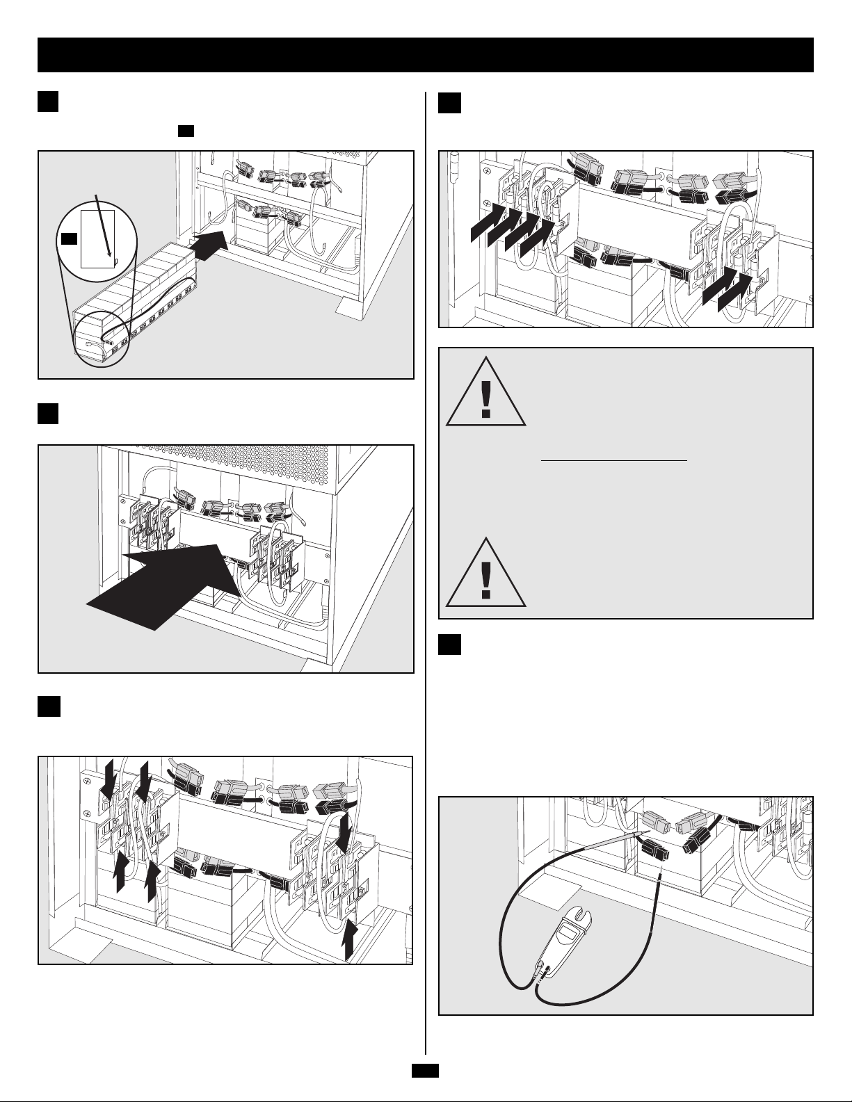
Slide the battery string with the BLACK cable next to it (on the left)
in the empty slot as shown. Make sure that the string is oriented as
shown in the diagram .
8A
8
8A
Replace the fuse block bracket. Make sure printing on bracket is
oriented so it is readable.
9
TERMINALS
Adding or Replacing Internal Batteries
(continued)
DANGER!
BATTERY CARTRIDGE FUSES MUST
BE INSERTED LAST DUE TO THE
DANGER OF POTENTIAL ARCING OF
CONNECTORS.
FUSE REPLA
CEMENT
The fuses protect against short circuit damage. If
a heavy overload or short circuit is encountered,
a fuse will blow. A battery pack with a blown fuse
will not deliver any output voltage to the UPS
system.
DANGER!
The fuses must be replaced by a qualified
electrician. To reduce the risk of fire, replace only
with fuses of the same type or rating (ULrecognized 30A 600VDC rated cartridge fuses).
Use a voltmeter (user-supplied) to test the voltage of the battery
pack. Observe proper polarity: connect the voltmeter's BLACK
probe to the battery pack's BLACK connector; connect the
voltmeter's RED probe to the battery pack's RED connector. To get
a proper reading, make sure the voltmeter's probes touch the metal
contacts inside the battery pack's connectors. The battery pack's
Acceptable DC Voltage Range is between 220 and 280V DC. If
several attempts at voltmeter tests yield results outside this range,
contact Tripp Lite for assistance in determining the possible causes
of the incorrect voltage reading.
12
Connect the BLUE and WHITE jumper cables on each internal
battery pack to its corresponding fuse block. See printing next to
fuse block to locate the correct fuse block for each cable.
10
Insert the battery cartridge fuses into each fuse block. The fuses are
identical, and can be inserted into any of the blocks. Make sure that
the fuses are firmly snapped into place.
11
240
Page 5
5
Adding or Replacing Internal Batteries
(continued)
Connect the BLACK cable for each internal battery pack to the
nearest BLACK connector located inside the UPS system's battery
module.
Connect the RED cable for each internal battery pack to the nearest
RED connector located inside the UPS system's battery module.
Replace the battery access panel.
Return the UPS System to Normal Mode or completely turn it on,
depending on the procedure you followed in step 1. See “Operation
of Manual Bypass Switch” or “Turning the UPS On” in the
Operation section of the UPS System’s owner’s manual.
15
16
13
14
WARNING!
OBSERVE PROPER POLARITY!
Connect BLACK-to-BLACK and RED-to-RED.
Failure to observe proper polarity will cause
permanent damage to the UPS System and create
a potential for serious personal injury.
Warranty & Warranty Registration
LIMITED WARRANTY
Seller warrants this product, if used in accordance with all applicable instructions, to be free from original defects in material and workmanship for a period of 2 years (except U.S., Canada and Mexico: 1 year)
from the date of initial purchase. If the product should prove defective in material or workmanship within that period, Seller will repair or replace the product, in its sole discretion. Service under this Warranty
includes parts and Tripp Lite service center labor. Onsite service plans are available from Tripp Lite through authorized service partners (in most areas). Contact Tripp Lite Customer Service at (773) 869-1234 for
details. International customers should contact Tripp Lite support at intlservice@tripplite.com
THIS WARRANTY DOES NOT APPLY TO NORMAL WEAR OR TO DAMAGE RESULTING FROM ACCIDENT, MISUSE, ABUSE OR NEGLECT. SELLER MAKES NO EXPRESS WARRANTIES OTHER THAN
THE WARRANTY EXPRESSLY SET FORTH HEREIN. EXCEPT TO THE EXTENT PROHIBITED BY APPLICABLE LAW, ALL IMPLIED WARRANTIES, INCLUDING ALL WARRANTIES OF MERCHANTABILITY
OR FITNESS, ARE LIMITED IN DURATION TO THE WARRANTY PERIOD SET FORTH ABOVE; AND THIS WARRANTY EXPRESSLY EXCLUDES ALL INCIDENTAL AND CONSEQUENTIAL DAMAGES.
(Some states do not allow limitations on how long an implied warranty lasts, and some states do not allow the exclusion or limitation of incidental or consequential damages, so the above limitations or exclusions
may not apply to you. This Warranty gives you specific legal rights, and you may have other rights which vary from jurisdiction to jurisdiction).
Tripp Lite; 1111 W.35th Street; Chicago IL 60609; USA
WARNING: The individual user should take care to determine prior to use whether this device is suitable, adequate or safe for the use intended. Since individual applications are subject to great variation, the
manufacturer makes no representation or warranty as to the suitability or fitness of these devices for any specific application.
WARRANTY REGISTRATION
Visit www.tripplite.com/warranty today to register the warranty for your new Tripp Lite product.You'll be automatically entered into a drawing for a chance to win a FREE Tripp Lite product!*
* No purchase necessary.Void where prohibited. Some restrictions apply.See website for details.
Regulatory Compliance Identification Numbers
For the purpose of regulatory compliance certifications and identification, your Tripp Lite product has been assigned a unique series number. The series number can be found on the product nameplate label,
along with all required approval markings and information.When requesting compliance information for this product, always refer to the series number.The series number should not be confused with the marking
name or model number of the product.
Tripp Lite follows a policy of continuous improvement. Product specifications are subject to change without notice.
Page 6

6
Manual del Propietario
1111 W. 35th Street • Chicago, IL 60609 USA
(773) 869-1234 • www.tripplite.com
Derechos de Autor ©2007 Tripp Lite. Todos los derechos reservados.
SmartOnline™ es una marca registrada de Tripp Lite.
Módulos de Baterías Internas
Para usarse con los Sistemas UPS SmartOnline™Trifásicos
de Tripp Lite UPS que aceptan la conexión de módulos de
baterías Internas.
Modelo: SURBC2030
Advertencias de Seguridad Importantes
Añadiendo o Remplazando las Baterías
Internas
Garantía
6
7
10
English
1
Français
11
Advertencias de Seguridad Importantes
¡CONSERVE ESTAS INSTRUCCIONES! Este Manual del Propietario contiene instrucciones y advertencias importantes que deben ser seguidas
durante la instalación y operación de los Módulos de Baterías Internas SURBC2030. El Manual del Propietario incluido con productos compatibles
(Sistemas UPS y Compartimientos para Módulos de Baterías) incluyen instrucciones adicionales de seguridad que deben ser seguidas durante la
instalación y operación. El no hacer caso a estas instrucciones puede casar daño permanente al Sistema UPS (anulando su garantía) y crear un potencial
de serias heridas personales o incluso la muerte derivadas de alto voltaje letal.
• No use los Sistemas UPS o los Módulos de Baterías Internas de Tripp Lite en aplicaciones de Soporte de Vida en los que un mal funcionamiento o
falla de un Sistema UPS o Módulo de Baterías Internas de Tripp Lite puedan causar fallas o alterar significativamente el rendimiento del dispositivo
de Soporte de Vida.
• El Sistema UPS contiene su propia fuente de energía (batería). Las terminales de Salida pueden estar vivas aun cuando el UPS no esté conectado a un
suministro CA.
• Su UPS no requiere de mantenimiento de rutina. No abra el modulo de potencia del UPS por ningún motivo, no hay partes en el interior a las que el usuario
les necesite dar mantenimiento. Debido al riesgo de una descarga eléctrica, únicamente electricistas calificados deberán abrir el módulo de baterías.
• Debido a que las baterías presentan un riesgo de descargas eléctricas y quemaduras del alta corriente de un corto circuito, las baterías deben ser
remplazadas por personal de servicio capacitado que observe las debidas precauciones. Quítese relojes, anillos, y cualquier otro objeto de metal. Use
herramientas con asas/mangos aislantes. Utilice guantes y botas de hule. No deje herramientas o partes de metal arriba de la batería. No puentee o
haga corto circuito con las terminales de la batería con ningún objeto.
• No arroje las baterías al fuego. Las baterías del UPS son reciclables. Refiérase a las reglamentaciones locales acerca de cómo deshacerse de las
baterías o únicamente en los Estados Unidos, refiérase a estas fuentes para información del reciclaje: 1-800-SAV-LEAD (1-800-728-5323),
1-800-8-BATTERY (1-800-8-228-8379), o www.rbrc.com
• Las baterías internas deben ser remplazadas por baterías equivalentes disponibles en Tripp Lite.
• No opere su UPS sin baterías.
• Los fusibles de la batería deberán ser remplazados únicamente por personal autorizado de fábrica. Los fusibles quemados deberán ser remplazados
únicamente por fusibles del mismo número y tipo.
• Existen voltajes potencialmente letales dentro de esta unidad en tanto la suministro de la batería este conectado. El servicio y reparación deberá ser
hecho únicamente por personal capacitado. Durante cualquier trabajo de servicio el UPS deberá apagarse o puesto en derivación manual
• No conecte o desconecte el módulo de la batería mientras el UPS este operando con el suministro de la batería o cuando la unidad no esté en modo
de derivación.
Page 7

7
Las baterías están diseñadas para reemplazo Hot-Swap, lo
que permite que el equipo conectado reciba en forma
continua energía CA principal (pero no respaldo de la
batería en el caso de un apagón) durante el procedimiento
de instalación de la batería. Vea “Operación del
Interruptor de Derivación Manual” en la sección
Operación del Manual del Propietario del Sistema UPS.
Aunque las baterías puedan ser remplazadas de esta
manera, personal de servicio calificado puede desear
apagar el equipo totalmente durante la instalación de las
baterías. Vea “Apagando el UPS” en la sección Operación
del Manual del Propietario del Sistema UPS.
Los módulos de baterías internas deben se remplazados
por baterías equivalentes disponibles en Tripp Lite. El
aumentar módulos de baterías incrementará el tiempo de
recarga. Los modelos individuales pueden variar
ligeramente de los diagramas.
DIAGRAMA DEL CABLEADO DEL
MODULO DE BATERIAS INTERNAS
Personal de servicio calificado debe familiarizarse con el
diagrama del cableado de la batería antes de aumentar o
remplazar las baterías. El módlo de baterías puede aceptar
hasta cuatro módulos de baterías (Cada módulo se
compone de dos cadenas). El diagrama muestra a los
cuatro módulos de baterías conectadas para efectos de
ilustración únicamente. El número real de baterías
embarcadas con el UPS varía dependiendo del número del
modelo.
Añadiendo o Remplazando las Baterías Internas
¡PELIGRO!
¡ALTO VOLTAJE POTENCIALMENTE LETAL! ¡UNICAMENTE ELECTRICISTAS CALIFICADOS!
Siga todas las precauciones de seguridad descritas en la sección Seguridad antes de añadir o remplazar las baterías internas.
¡PELIGRO!
¡NO REMUEVA LA CUBIERTA PROTECTORA DE LA BATERIA!
No remueva la cubierta de plástico que protege a la batería. Esta cubierta está diseñada para prevenir contacto accidental
con la terminales de las baterías. El contacto con las terminales crean un potencial de lesiones severas o muerte por alto
voltaje letal. No permita que herramientas u otros objetos de metal tengan contacto con las terminales.
¡PRECAUCION!
¡LOS MODULOS DE BATERIA SON PESADOS!
Use toda la ayuda y asistencia que sea necesaria.
¡ADVERTENCIA!
CHEQUE EL VOLTAJE DEL MODULO DE BATERIAS ANTES DE COMPLETAR LA INSTALACION
No instale módulos de baterías con voltajes CD fuera de un rango aceptable. (Esto puede comprometer la capacidad de
respaldo de las baterías).
¡NOTA!
Cada módulo de baterías consiste de dos cadenas de baterías una cadena con un cable NEGRO y otra cadena con un cable
ROJO.
Cable Blanco
Cable Azul
Cable Rojo (+)
Cable Negro(-)
Conector
Trasero de
la Batería del
Sistema UPS
Conector
Trasero de
la Batería del
Sistema UPS
Soporte del Bloque de Fusibles
Page 8

8
Añadiendo o Remplazando las Baterías Internas
(continuación)
Remueva el panel de acceso a la batería, localizado en el FRENTE
del sistema UPS.
2
Desconecte los cables ROJO y NEGRO conectados a cada módulo
de baterías Internas.
3
Remueva el cartucho de fusibles de la batería de cada bloque de
fusibles. Guarde los fusibles.
4
Desconecte los cables de puenteo AZUL y BLANCO conectado a
cada bloque de fusibles.
5
¡PRECAUCION!
Cuando desconecte los cables de puenteo
jálelos hacia fuera del bloque de fusibles con
fuerza uniforme. No los menee o zarandee de
lado a lado, ya que esto puede dañar al conector.
Dependiendo de su preferencia, coloque el sistema UPS en modo de
Derivación o apáguelo completamente. Vea “Operación del
Interruptor de Derivación Manual” o “Apagando el UPS” en la
sección Operación del Manual del Propietario del Sistema UPS.
1
Remueva el soporte del bloque de fusibles.
6
Deslice la cadena de baterías con el cable ROJO en una ranura
vacía dentro del compartimiento de la batería como se muestra.
Asegúrese que la cadena de baterías está orientada como se muestra
en el diagrama .
NOTA Si el conector de la batería auxiliar estorba, remueva su tornillo de montaje y
reposicione el cable para permitir que haya un espacio adecuado para añadir la cadena
de baterías .
7B
7A
7
7A
7B
TERMINALES
Page 9

9
Añadiendo o Remplazando las Baterías Internas
(continuación)
Deslice la cadena de baterías que tiene el cable NEGRO junto a ella
(a la izquierda), en una ranura vacía como se muestra. Asegúrese
que la cadena esta orientada como se muestra en el diagrama .
8A
8
8A
Recoloque el soporte del bloque de fusibles. Asegúrese que las
impresiones en el soporte estén orientadas de forma que sean leibles.
9
TERMINALES
Conecte los cables de puenteo AZUL y BLANCO en cada uno de
los módulos de baterías internas a su bloque de fusibles
correspondiente. Lea el impreso junto al bloque de fusibles para
localizar el bloque de fusibles correcto para cada cable.
10
Inserte los cartuchos de fusibles de la batería en cada bloque de
fusibles. Los fusibles son idénticos y pueden insertarse en cualquiera
de los bloques. Asegúrese de que los fusibles están firmemente
sujetos en su lugar.
11
¡PELIGRO!
LOS CATUCHOS DE LOS FUSIBLES DE
LA BATERIA DEBEN SER INSERTADOS
HASTA EL ULTIMO DEBIDO AL
PELIGRO DE ARCOS VOLTAICOS DE
LOS CONECTORES
REMPLAZO DE LOS FUSIBLES
Los fusibles protegen contra daños por corto
circuitos. Si se presentara una fuerte sobrecarga
o corto circuito el fusible se quemará. Un módulo
de baterías con un fusible quemado no entregará
ninguna salida de voltaje al sistema UPS.
¡PELIGRO!
Los fusibles deben ser remplazados por un
electricista calificado. Para reducir el riesgo de
un incendio, remplácelos únicamente por
fusibles del mismo tipo o clase (Cartuchos de
fusibles de clase 30A 600VCD reconocidos por UL).
Use un voltímetro (suministrado por el usuario ) para revisar el
voltaje del módulo de baterías. Observe la polaridad adecuada:
conecte la punta de prueba NEGRA del voltímetro al conector
NEGRO del módulo de baterías, conecte la punta de prueba ROJA
del voltímetro en el conector ROJO del módulo de baterías. Para
obtener una lectura adecuada, asegúrese que las puntas de prueba del
voltímetro toquen los contactos metálicos del conectores del módulo
de baterías. El rango de voltaje CD aceptable, del módulo de
baterías, es entre 220 y 280V CD. Si varios intentos con el
voltímetro dan resultados fuera de este rango, comuníquese con
Tripp Lite para obtener asistencia para determinar las posibles
causas de la lectura incorrecta del voltaje.
12
240
Page 10

10
Añadiendo o Remplazando las Baterías Internas
(continuación)
Conecte el cable NEGRO para cada módulo de baterías internas al
conector NEGRO más cercano localizado adentro del módulo de
baterías del sistema UPS.
Conecte el cable ROJO para cada módulo de baterías internas al
conector ROJO más cercano localizado adentro del módulo de
baterías del sistema UPS.
Remplace el panel de acceso a las baterías.
Regrese el Sistema UPS al Modo Normal o enciéndalo
completamente, dependiendo del procedimiento que haya seguido en
el paso 1. Vea “Operación del Interruptor de Derivación Manual” o
“Encendiendo el UPS” en la sección Operación del Manual del
Propietario del Sistema UPS.
15
16
¡ADVERTENCIA!
¡OBSERVE LA POLARIDAD CORRECTA!
Conecte NEGRO-a-NEGRO y ROJO-a-ROJO. El no observar la correcta polaridad puede causar daño permanente al Sistema
UPS además de poder causar serias lesiones personales.
13
14
Garantía
GARANTIA LIMITADA
El Vendedor garantiza este producto, si es usado de acuerdo a las instrucciones aplicables verificadas por el Servicio de Instalación Inicial de Tripp Lite de estar libre de defectos de origen en materiales y mano
de obra por un periodo de dos años (excepto los Estados Unidos, Canadá y México.1 año) a partir de la fecha de la compra inicial. Si el producto mostrara defectos en materiales o mano de obra dentro de ese
periodo, el Vendedor reparará o remplazará el producto a su completa discreción. El servicio bajo esta garantía incluye partes y mano de obra del Centro de Servicio de Tripp Lite. Planes de servicio en sitio
están disponibles de Tripp Lite a través de "Service Partners" autorizados (en la mayoría de las áreas). Comuníquese con el Servicio a Clientes de Tripp Lite al (773) 869-1234 para más información. Clientes
internacionales deberán contactar al soporte de Tripp Lite en intlservice@tripplite.com ESTA GARANTIA NO APLICA POR EL USO NORMAL O DAÑOS RESULTANTES DE ACCIDENTES, MAL USO, ABUSO
O NEGLIGENCIA. EL VENDEDOR NO EXPRESA OTRAS GARANTIAS QUE NO SEA LA GARANTIA EXPRESAMENTE ESTABLECIDA AQUI. EXCEPTO POR LO PROHIBIDO POR LAS LEYES APLICABLES,
TODAS LAS GARANTIAS IMPLICADAS, INCLUYENDO TODAS LAS GARANTIAS DE MERCANTIBILIDAD O CONVENIENCIA, SON LIMITADAS AL PERIODO ESTABLECIDO CON ANTERIORIDAD ARRIBA,
Y ESTA GARANTIA EXPRESAMENTE EXCLUYE TODOS LOS DAÑOS INCIDENTALES Y CONSEQUENTES.
Tripp Lite; 1111 W.35th Street; Chicago IL 60609; USA
ADVERTENCIA: Los usuarios deberán tener cuidado en determinar, en forma individual, antes de usar este dispositivo si es adecuado o seguro para el uso que se le quiere dar. Dado que las aplicaciones
individuales están sujetas a una gran variedad, el fabricante no garantiza ni establece la adecuación, conveniencia o correctibilidad de su uso para una aplicación específica.
Cumplimiento de las normas de los números de identificación
Para fines de identificación y certificación del cumplimiento de las normas, su producto Tripp Lite tiene asignado un número de serie único. Puede encontrar el número de serie en la etiqueta de la placa de
identificación del producto, junto con los símbolos de aprobación e información requeridos. Al solicitar información sobre el cumplimiento de las normas para este producto, siempre mencione el número de serie.
El número de serie no debe ser confundido con el nombre de identificación ni con el número de modelo del producto.
Tripp Lite tiene una política de mejoramiento continuo. Las especificaciones están sujetas a cambio sin previo aviso.
LEA SU INSTRUCTIVO
CONSULTE SUS CONDICIONES DE GARANTÍA POR PRODUCTO
PÓLIZA DE GARANTÍA
Este equipo marca Tripp Lite, modelo _______________ está garantizado por TRIPP LITE, que tiene su domicilio en la calle de Sierra Candela No.111-107, Col Lomas de Chapultepec, CP 11000, México,
DF, y puede hacer efectiva su garantía así como obtener partes, componentes, consumibles y accesorios en el Centro de Servicio Q PLUS ubicado en Av Coyoacan 931, Col. Del Valle, C.P. 03120 México.
D.F., tel. 50 00 27 00 contra cualquier defecto de fabricación y funcionamiento, imperfecciones de materiales, piezas, componentes y mano de obra al consumidor acorde a la siguiente tabla:
Producto Modelo Vigencia
Sistema de Energía Ininterrumpible (UPS) Familia: BC, OMNI, SMART, SMARTONLINE MONOFASICOS 2 Años
Sistema de Energía Ininterrumpible (UPS) Familia: SMARTONLINE 3PH 1 Año
Regulador y Acondicionador de Tensión Familia: LS, LC 2 Años
Inversores Familia: APS, PV 2 Años
Multiplexor y Conmutador Familia: KVM 5 Años
Conmutador Modelo: B020-016 6 Meses
Supresor de Picos de Tensión Familia: PROTECT IT, ISOBAR 25 Años
CONDICIONES
1. Para hacer válida su garantía no podrán exigirse mayores requisitos que la presentación de esta póliza debidamente llenada y sellada por el establecimiento que lo vendió junto con el producto en el lugar
donde fue adquirido.
2. TRIPP LITE, se compromete a reparar, y en caso de que a su juicio no sea posible la reparación, a cambiar el equipo, así como las piezas y componentes defectuosos del mismo sin cargo alguno para el
propietario durante el periodo de garantía, así como los gastos de transportación razonablemente erogados del producto que deriven de su cumplimiento, dentro de su red de servicio.
3. El tiempo de reparación en ningún caso será mayor de 30 días contados a partir de la fecha de recepción del producto en el Centro Autorizado de Servicio, en donde también podrán adquirir refacciones
y partes.
4. En caso de que la presente póliza de garantía se extraviara, el consumidor puede recurrir a su proveedor para que expida un duplicado de la póliza de garantía, previa presentación de la nota de compra
o factura correspondiente.
EXCLUSIONES
Esta garantía no es válida en los siguientes casos:
a) Cuando el producto se hubiese utilizado en condiciones distintas a la normales.
b) Cuando el producto no hubiese sido operado de acuerdo con el instructivo de uso que se le acompaña.
c) Cuando el producto hubiese sido alterado o reparado por personas no autorizadas por el fabricante nacional, importador o comercializador responsable respectivo.
Este equipo fue vendido por: _____________________________________con domicilio en ________________________________________________el día _____ de ___________ de ________, fecha a
partir de la que inicia la presente garantía.
13/14
Page 11

11
Manuel du propriétaire
1111 W. 35th Street • Chicago, IL 60609 USA
(773) 869-1234 • www.tripplite.com
Copyright© 2007 Tripp Lite. Tous droits réservés.
SmartOnline™ est une marque déposée de Tripp Lite
Bloc-batteries internes
Pour les systèmes d'onduleur Tripp Lite SmartOnline
™
triphasés acceptant la connexion de bloc-batteries internes.
Modèle : SURBC2030
Importantes consignes de sécurité
Ajout et remplacement des batteries
internes
Garantie
11
12
15
English
1
Español
6
Importantes consignes de sécurité
CONSERVER CES CONSIGNES! Ce manuel contient des instructions et des mises en garde qu'il faut suivre pendant l'installation et l'utilisation des
bloc-batteries internes SURBC2030. Les manuels du propriétaire joints aux produits compatibles (systèmes d'onduleur et compartiments de module de
batterie) comprennent d'autres consignes de sécurité qu'il faut suivre pendant l'installation et l'utilisation. Le défaut d'observer la bonne polarité
endommagera l'onduleur de façon permanente (annulant la garantie) et pourrait entraîner des blessures sérieuses ou la mort dues à la haute tension.
• Ne pas utiliser les systèmes d'onduleur ou les bloc-batteries internes de Tripp Lite dans les applications médicales de survie où un mauvais
fonctionnement ou une panne de leur part pourraient entraîner une panne de l'équipement médical de survie ou altérer sa performance de façon
importante.
• L'onduleur UPS comprend sa propre source d'énergie (batterie). Les bornes de sortie pourraient être alimentées même quand l'onduleur n'est pas
branché sur le courant alternatif.
• Votre onduleur ne nécessite aucun entretien de routine. N'ouvrir le module d'alimentation de l'onduleur sous aucun prétexte; aucune pièce interne
n'est réparable par l'utilisateur. À cause du risque de choc électrique, seuls des électriciens qualifiés devraient ouvrir le module de la batterie.
• À cause du risque de choc électrique et de brûlures dus au courant élevé de court-circuit, seul un personnel de réparation expérimenté observant les
précautions appropriées devrait changer les batteries. Enlever montres, bagues et autres objets de métal. Utiliser des outils avec des poignées isolées.
Porter des gants et des bottes de caoutchouc. Ne pas déposer d'outils ou de pièces de métal sur le dessus des batteries. Ne pas établir de court circuit
ou de pont entre les bornes de la batterie avec un quelconque objet.
• Ne pas jeter les batteries au feu. Les batteries d'onduleur sont recyclables. Consultez les codes locaux pour les exigences d'élimination des déchets,
ou au E.-U. seulement, consultez ces sources pour des renseignements concernant le recyclage : 1-800-SAV-LEAD (1-800-728-5323),
1-800-8-BATTERY (1-800-8-228-8379), ou www.rbrc.com.
• Il faut remplacer les batteries internes par des batteries équivalentes en vente chez Tripp Lite.
• Ne pas faire fonctionner votre onduleur sans batterie.
• Seul du personnel d'usine autorisé devrait remplacer les fusibles de batterie. Il faudrait remplacer les fusibles sautés par des fusibles de même numéro
et de même type.
• Des tensions mortelles existent potentiellement dans cette unité aussi longtemps que le bloc d'alimentation par batterie est connecté. Seul du personnel
expérimenté devrait s'occuper du service et des réparations. Pendant tout travail de réparation, l'onduleur devrait être mis hors tension ou en dérivation
manuelle.
• Ne pas connecter ou déconnecter les modules de batterie quand l'onduleur fonctionne sur le bloc alimentation de batterie ou quand l'unité n'est pas en
mode dérivation.
Page 12

12
Les batteries sont conçues pour le remplacement à chaud
qui permet à l'équipement connecté de recevoir le courant
CA du réseau en permanence (mais pas de secours de
batterie en cas de panne) pendant la procédure d'installation
de la batterie. Voir “ Fonctionnement du commutateur de
dérivation manuelle ” dans la section Fonctionnement du
manuel du propriétaire du système d'onduleur. Bien que les
batteries puissent être remplacées à chaud, du personnel
qualifié pourrait arrêter l'onduleur pendant l'installation de
la batterie. Voir “ Arrêter l'onduleur ” dans la section
Fonctionnement du manuel du propriétaire du système
d'onduleur.
Il faut remplacer les batteries internes par des batteries
équivalentes en vente chez Tripp Lite. L'ajout de blocs de
batterie augmentera la durée de la recharge. Les modèles
peuvent être légèrement différents des schémas.
SCHÉMA DU CÂBLAGE INTERNE
D'UN BLOC DE BATTERIE
Le personnel de service qualifié devra se familiariser avec
le schéma du câblage avant d'ajouter ou de remplacer des
batteries. Le module de batterie peut accepter jusqu'à quatre
blocs de batterie (chaque bloc consistant en deux chaînes).
Le schéma montre les quatre blocs de batterie connectés,
uniquement à des fins illustratives. Le nombre réel de
batteries expédié avec l'onduleur dépend du numéro de
modèle.
Ajout et remplacement des batteries internes
DANGER!
HAUTE TENSION POTENTI MORTELLE! POUR ÉLECTRICIENS QUALIFIÉS UNIQUEMENT!
Suivre toutes les mesures de sécurité de la section Sécurité avant d'ajouter ou de remplacer batteries internes.
DANGER!
NE PAS RETIRER LA GAINE DE BATTERIE!
Ne pas retirer la gaine de plastique recouvrant les chaînes de batterie. Cette gaine est conçue pour empêcher un contact
accidentel avec les bornes des batteries individuelles. Le contact avec les bornes pourrait entraîner des blessures
sérieuses ou la mort dues à une haute tension fatale. Ne pas laisser des outils ou d'autres objets métalliques venir en
contact avec les bornes.
ATTENTION!
LES BLOCS DE BATTERIE SONT LOURDS!
Demander l'aide d'assistants au besoin.
MISE EN GARDE!
VÉRIFIER LA TENSION DU BLOC DE BATTERIE AVANT DE TERMINER L'INSTALLATION
Ne pas installer de blocs de batterie dont les tensions CC ne sont pas dans les plages acceptables.
(Ils pourraient compromettre les capacités de secours de la batterie).
NOTE!
Chaque bloc de batterie consiste en deux chaînes de batteries: Une chaîne avec un câble NOIR et une chaîne avec un câble ROUGE.
Fil blanc
Fil bleu
Fil rouge (+)
Fil noir (–)
Connecteur
Onduleur
Arrière de
la batterie
Connecteur
Onduleur
Arrière de
la batterie
Attache de boîte de fusible
Page 13

13
Ajout et remplacement des batteries internes
(suite)
Placer l'onduleur en mode de dérivation ou l'arrêter complètement, à
votre choix. Voir “ Fonctionnement du commutateur de dérivation
manuelle ” ou “ Arrêter l'onduleur ” dans la section Fonctionnement
du manuel du propriétaire du système d'onduleur.
1
Retirer le panneau d'accès à la batterie, situé à l'AVANT de
l'onduleur.
2
Déconnecter les câbles ROUGE et NOIR attachés à chaque bloc de
batterie interne.
3
Retirer les fusibles à cartouche de batterie de chaque bloc-fusibles.
Conserver les fusibles.
4
Déconnecter les câbles de pontage BLEU et BLANC attaché à
chaque bloc-fusibles.
5
ATTENTION!
Lorsque vous déconnectez le câble de pontage,
les retirer du bloc-fusibles avec une force égale.
Ne pas les secouer d'un bord à l'autre car cela
pourrait endommager le connecteur.
Retirer l'attache du bloc-fusibles.
6
Faire glisser la chaîne de batteries avec un câble ROUGE dans une
fente vide du compartiment de batterie comme montré. Vérifier que
la chaîne est orientée comme le montre le schéma .
NOTE : Si le connecteur de la batterie auxiliaire gêne, retirer sa vis de montage et
déplacer le câble afin de laisser suffisamment de place pour ajouter les chaînes de
batterie .
7B
7A
7
7A
7B
BORNES
Page 14

14
Faire glisser la chaîne de batterie avec le câble NOIR à côté (à
gauche) dans la fente vide comme montré. Vérifier que la chaîne est
orientée comme le montre le schéma .
8A
8
8A
Replacer l'attache du bloc-fusibles. Vérifier que l'impression sur
l'attache est orientée pour être lisible.
9
BORNES
Ajout et remplacement des batteries internes
(suite)
DANGER!
IL FAUT INSÉRER LES FUSIBLES À
CARTOUCHE DE BATTERIE EN
DERNIER À CAUSE DU DANGER
POTENTIEL D'ARC ÉLECTRIQUE
ENTRE LES CONNECTEURS.
REMPLA
CEMENT DE FUSIBLE
Les fusibles protègent contre les court-circuits.
En cas de surcharge intense ou de court-circuit,
un fusible sautera. Un bloc batterie avec un
fusible sauté ne livrera pas de tension de sortie à
l'onduleur.
DANGER!
Un électricien qualifié doit remplacer les fusibles.
Pour réduire le risque d'incendie, remplacer
uniquement par des fusibles du même type ou
classe (fusibles à cartouche 30A 600VDC
homologués UL).
Utiliser un voltmètre (fourni par l'utilisateur) pour tester la tension
du bloc de batterie. Observer la bonne polarité : Connecter la sonde
NOIRE du voltmètre au connecteur NOIR du bloc de batterie et
sonde ROUGE au connecteur ROUGE. Pour obtenir une bonne
lecture, vérifier que les sondes du voltmètre touchent les contacts
métalliques à l'intérieur des connecteurs du bloc de batterie. La
plage de tension CC acceptable d'un bloc de batterie se situe
entre 220et 280 v CC. Si lors de plusieurs essais, les tests du
voltmètre indique des résultats hors de cette plage, contacter Tripp
Lite pour de l'assistance afin de déterminer les causes possibles de
ces mauvaises lectures de tension.
12
Connecter les câbles de pontage BLEU et BLANC de chaque bloc
de batterie interne à son bloc-fusibles correspondant. Voir
l'impression à côté de chaque bloc-fusibles pour repérer le celui qui
correspond à chaque câble.
10
Retirer les fusibles à cartouche de batterie de chaque bloc- fusibles.
Les fusibles sont identiques et peuvent être insérer dans n'importe quel
bloc. Vérifier que les fusibles sont bien enclenchés.
11
240
Page 15

15
Ajout et remplacement des batteries internes
(suite)
Connecter le câble NOIR de chaque bloc de batterie interne au plus
proche connecteur NOIR situé à l'intérieur du module de batterie de
l'onduleur.
Connecter le câble ROUGE de chaque bloc de batterie interne au
plus proche ROUGE situé à l'intérieur du module de batterie de
l'onduleur.
Reposer le panneau d'accès à la batterie.
Remettre l'onduleur en mode Normal ou le remettre en marche
complètement, selon la procédure suivie à l'étape 1. Voir
“ Fonctionnement du commutateur de dérivation manuelle ” ou
“ Arrêter l'onduleur ” dans la section Fonctionnement du manuel du
propriétaire du système d'onduleur.
15
16
MISE EN GARDE!
OBSERVER LA BONNE POLARITÉ!
Connecter NOIR-à-NOIR et ROUGE-àROUGE. Ne pas observer la bonne polarité
endommagera l'onduleur de façon
permanente et créera l'éventualité de
blessures personnelles sérieuses.
13
14
Garantie
GARANTIE LIMITÉE À VIE
Le vendeur garantit que ce produit, s'il est utilisé selon toutes les consignes applicables telles que vérifiées par le service de mise en route de Tripp Lite, est exempt de défectuosités initiales de matériel et de
fabrication pour une période d'un an (aux É.-U. et au Canada) à dater de sa mise en route. Si le produit s'avère défectueux sur le plan matériel ou de la main-d'oeuvre cette période, le vendeur le réparera ou le
remplacera, à sa discrétion. Dans le cadre de cette garantie, le service comprend les pièces et la main-d'oeuvre du centre de service Tripp Lite. Tripp Lite offre des plans de service sur les lieux grâce à des
partenaires de service autorisés (dans la plupart des régions). Appeler l'assistance à la clientèle de Tripp Lite au (773) 869-1234 pour des détails. Les clients internationaux doivent communiquer avec le support
de Tripp Lite à intlservice@tripplite.com CETTE GARANTIE NE S'APPLIQUE PAS À L'USURE NORMALE OU AUX DÉGATS DUS À UN ACCIDENT, UNE MAUVAISE UTILISATION, UN ABUS OU UNE
NÉGLIGENCE. LE VENDEUR N'ACCORDE AUCUNE GARANTIE EXPRESSE AUTRE QUE CELLE CONTENUE DANS LES DISPOSITIONS CI-DESSUS SAUF DISPOSITIONS CONTRAIRES PRÉVUES PAR
LA LOI, TOUTES LES GARANTIES IMPLICITES, Y COMPRIS LES GARANTIES DE QUALITE COMMERCIALE ET D'ADAPTATION A UN USAGE PARTICULIER, SONT LIMITÉES EN DURÉ À LA PÉRIODE
DE GARANTIE PRÉCITÉE. CETTE GARANTIE EXCLUE EXPRESSÉMENT LES DOMMAGES ACCESSOIRES ET INDIRECTS. (Certains états n'autorisent pas les restrictions sur la durée d'une garantie
implicite, ni l'exclusion ni la restriction des dommages accessoires ou indirects. Par conséquent, ces restrictions ou exclusions pourraient ne pas s'appliquer à votre cas. Cette garantie vous donne des droits
particuliers et vous pourriez avoir d'autres droits qui varient d'une juridiction à l'autre.)
1111 W. 35th Street, Chicago, IL 60609 USA
MISE EN GARDE! MISE EN GARDE : L'utilisateur individuel doit prendre soin de déterminer avant l'usage si cet appareil est convenable, adéquat et sûr pour l'usage prévu. Étant donné que les applications
individuelles varient énormément, le fabricant n'émet aucune représentation ni garantie quant à la l'aptitude ou adaptation de ces appareils à une application particulière.
Numéros d'identification de conformité aux règlements
À des fins de certification et d'identification de conformité aux règlements, votre produit Tripp Lite a reçu un numéro de série unique. Ce numéro se retrouve sur la plaque signalétique du produit, avec les
inscriptions et informations d'approbation requises. Lors d'une demande d'information de conformité pour ce produit, utilisez toujours le numéro de série. Il ne doit pas être confondu avec le nom de la marque
ou le numéro de modèle du produit.
La politique de Tripp Lite est celle d'une amélioration continuelle. Les spécifications peuvent être modifiées sans préavis.
Page 16

16
200702236
93-2659
1111 W. 35th Street, Chicago, IL 60609 USA
(773) 869-1234 • www.tripplite.com
 Loading...