

Page 1

Warranty
Registration:
register online today for a
chance to win a FREE Tripp Lite
product—www.tripplite.com/warranty
Owner’s Manual
SU20KXFMRT4U
20kVA Rackmount/Tower Isolation Transformer
Introduction 2
Important Safety Warnings 2
Features 3
Horizontal Rack Mounting 4
Connection 5
Storage & Service 7
Warranty & Warranty Registration 7
1111 W. 35th Street, Chicago, IL 60609 USA • www.tripplite.com/support
Copyright © 2013 Tripp Lite. All rights reserved.
1
Page 2
Introduction
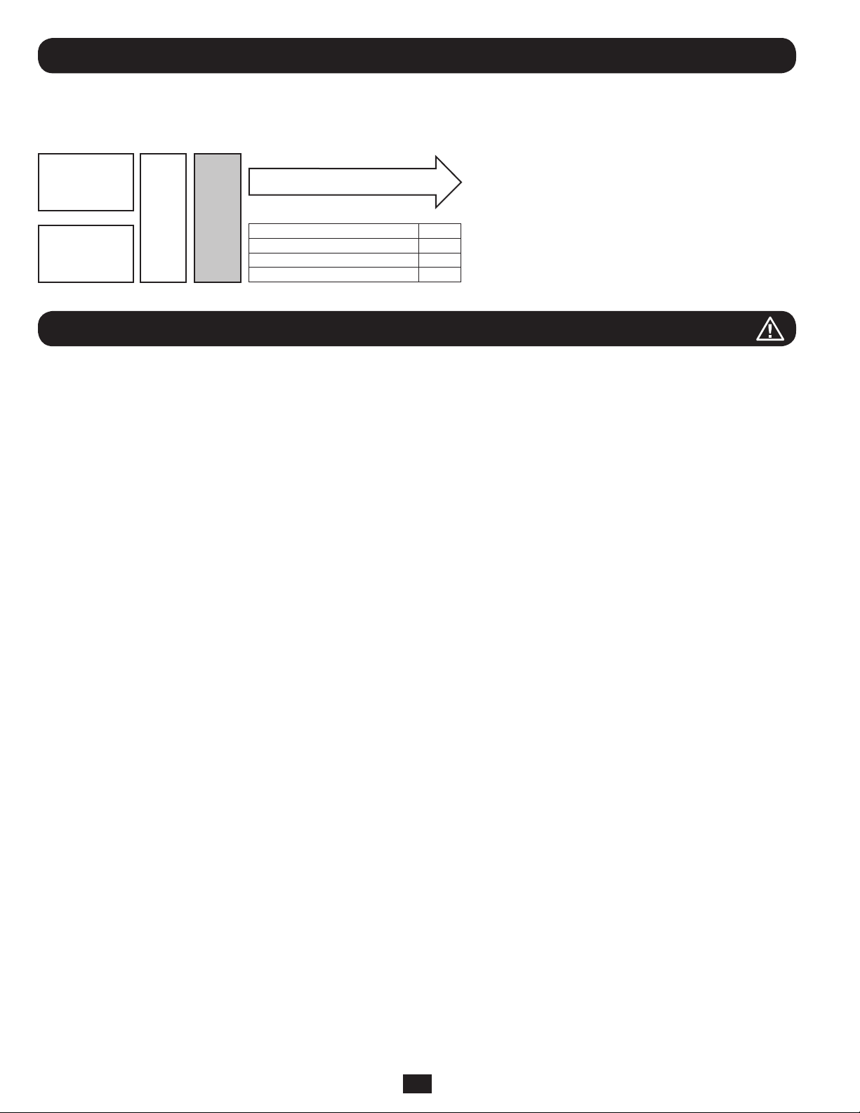
The 20kVA rackmount/tower isolation transformer allows you to provide an isolated output to your connected load at 120/240V split-phase
from a single-phase 208V/60Hz or 240V/60Hz AC power source.
Typical 20kVA Configuration (20kVA max load)
10kVA UPS
10kVA UPS
Parallel
PDU
XFMR
Redundant Operation NO
Fault-Tolerance NO
Hot-Swappable UPS Replacement YES
Increased Capacity YES
Loads 10-20kVA
Important Safety Warnings
SAVE THESE INSTRUCTIONS. This manual contains important instructions and warnings that should be followed during the installation and
maintenance of all Tripp Lite transformers.
Location Warnings
• Install your transformer indoors, away from excess moisture or heat, direct sunlight, dust and conductive contaminants.
• Install your transformer in a structurally sound area. Your transformer is heavy; take care when moving and lifting the unit.
• Only operate your transformer at indoor temperatures between 32° F and 104° F (between 0° C and 40° C). For best results, keep indoor
temperatures between 62° F and 84° F (between 17° C and 29° C).
• Leave adequate space around all sides of the transformer for proper ventilation.
• Do not install the transformer near magnetic storage media, as this may result in data corruption.
Equipment Connection Warnings
• Use of this equipment in life support applications where failure of this equipment can reasonably be expected to cause the failure of the
life support equipment or to signicantly affect its safety or effectiveness is not recommended. Do not use this equipment in the presence
of a ammable anesthetic mixture with air, oxygen or nitrous oxide.
• When connecting to a UPS, the UPS is connected to a DC energy source (battery). The output terminals may be live even when the UPS is
not connected to an AC supply.
Maintenance Warnings
• Your transformer does not require routine maintenance. Do not open for any reason. There are no user-serviceable parts inside.
2
Page 3
Features
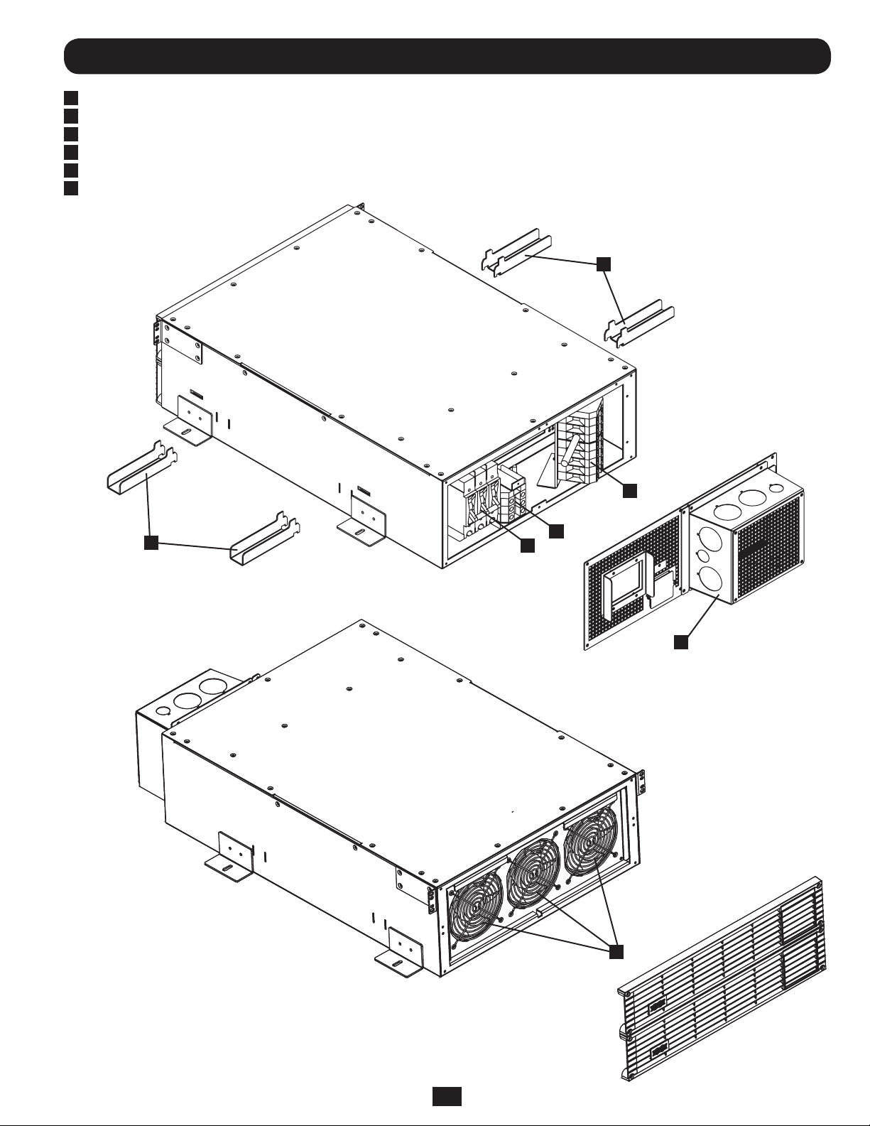
1
Circuit Breaker
2
AC Input Voltage Selection Terminal Block
3
Main Terminal Block (AC Input/Output of the Unit)
4
Lifting Handles
5
Conduit Landing and Wiring Access Box
6
Redundant Ventilation Fans
4
3
4
Rear View
2
1
5
Front View
3
6
Page 4
Horizontal Rack Mounting
Note: Use the following mounting instructions with standard
rack enclosures and 4-post open frame racks only. Due to the
weight of the transformer, it must only be placed/mounted in
the lower portion of the rack.
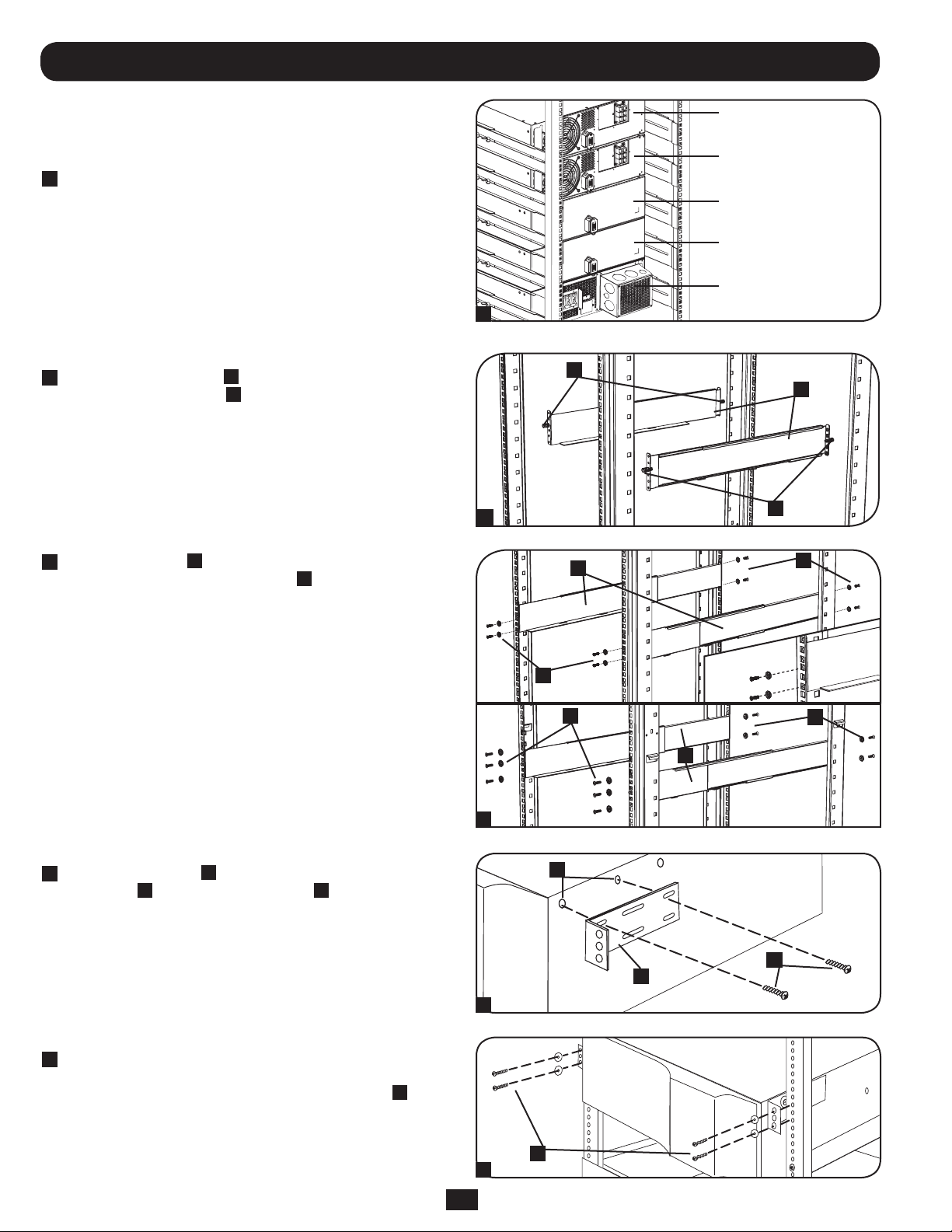
1
It is important to note that in order to accommodate paralleling
applications, equipment must be mounted in order of weight,
starting at the bottom with the heaviest item rst, in the
following order (see diagram): Transformer, Battery Modules,
UPS Power Modules. Note: The power modules, battery
modules and transformer must be installed on separate and
individual sets of rack shelves, which are included with each
module.
2
The included plastic pegs
A
will temporarily support the
empty rackmount shelves B while you install the permanent
mounting hardware. Insert a peg near the center of the front
and rear bracket of each shelf as shown. (Each front bracket
has 6 holes.) The pegs will snap into place.
After installing the pegs, expand each shelf to match the depth
of your rack rails. The pegs will t through the square holes
in the rack rails to support the shelves. Refer to the rack unit
labels to conrm that the shelves are level in all directions.
Note: The support ledge of each shelf must face inward.
3
Secure the shelves
B
to the mounting rails permanently using
the included screws and cup washers C as shown.
• For 2U equipment mounting, place 4 screws total at the
front and 4 screws total at the back.
• For 3U equipment mounting, place 6 screws total at the
front and 4 screws total at the back.
• For 4U equipment mounting, place 6 screws total at the
front and 6 screws total at the back.
Tighten all screws before proceeding.
Warning: Do not attempt to install your equipment until
you have inserted and tightened the required screws.
The plastic pegs will not support the weight of your
equipment.
UPS Power Module
UPS Power Module
Battery Module
Battery Module
Transformer
1
A
B
2
B
A
C
C
C
C
B
3
4
Attach mounting ears
D
to the front mounting holes of your
equipment E using the screws provided F. The ears should
face forward.
5
Using an assistant, lift your equipment and slide it onto the
mounting shelves. Attach your equipment to the rack by
passing the screws, nuts and washers (user-provided)
through its mounting ears and into the rack rails.
E
F
D
4
G
G
5
4
Page 5
Connection
Hardwiring Cautions
• Wiring must be done by a qualied electrician.
• When making wiring connections, observe the cable connection regulations and overcurrent protection requirements appropriate to your
area [such as U.S. National Electrical Code (NFPA 70)] at all times. Be sure to install an easily accessible disconnect switch in your
installation wiring so you may cut off the UPS’s AC input during res and other emergencies. Ensure that cables are tted with cable
sleeves and are secured by connector clamps. Tighten connections with a torque of not less than 24-28 inch-pounds (2.7-3.2 Nm).
• Make sure that your equipment is properly grounded.
• Using cables of improper size may damage your equipment and cause re hazards. Choose appropriate cabling and protection circuits to
make wiring connections. Ground conductors are recommended to be the same size and type as the power conductors used.
Input & Output* Ratings and Recommended Wire Sizing
For Capacity Operation
Input Voltage
Models (Bundles)
SU20KXFMRT4U 208V 80A 100A #3 AWG 67A #4 AWG
* Input/Output – hardwired. ** OCPD – Overcurrent protective device.
Note: Prior to terminal wiring connection, set input voltage on transformer to 208V or 240V.
(L-L)
240V 80A 100A #3 AWG 77A #4 AWG
Max Rated
Input Current
Input Service
OCPD**
Typical Input
Wire Size
Max Rated
Output Current
Typical Output
Wire Size
Typical Terminal Wiring Connections
SUPDMB20KHW – Typical UPS Source MBP/PDU
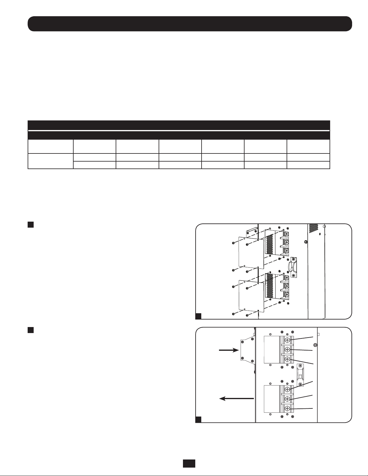
1
Unscrew the 2 screws to remove the Input and Output Terminal
Access covers.
2
Connect the Input (L1, L2, G) and Output (L1, L2, G) according
to markings on the connectors as seen in the diagram below.
Be sure to connect one set of wires to the input terminals and
the other set to the output terminals. The MBP/PDU output will
be the source for the isolation transformer input.
IN
OUT
1
L2
IN
GROUND
L1
L2
OUT
GROUND
L1
2
5
Page 6
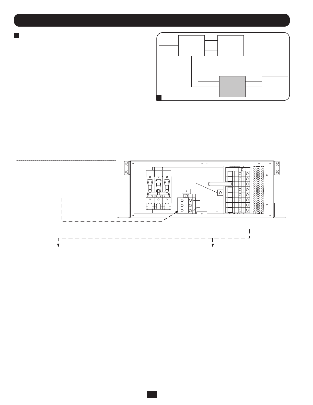
IN
LINE IN
OUT
L1 IN (TO TERM. 4) 120V LINE OUT
GROUND IN (TO TERM. 5) 120V LINE OUT
L2 IN (TO TERM. 6) 240V LINE OUT
L2 OUT
GROUND OUT
L1 OUT
PDU
TRANSFORMER CUSTOMER LOAD
UPS
Connection continued
3
Connect the hardwired input/output AC power connections
located on the PDU. The AC input cord attaches to the facility’s
AC source while the AC output cord connects to the intended
equipment.
Isolation Transformer Connection Diagram
AC INPUT SELECTION TERMINAL BLOCK
FOR 208 VAC INPUT PUT THE JUMPER BETWEEN #2 AND #3
FOR 240 VAC INPUT PUT THE JUMPER BETWEEN #2 AND #1
NOTE: THE DEFAULT POSITION OF THE JUMPER IS 208 VAC
3
Typical UPS Configuration with
Output Isolation Transformer
4
5
6
7
8
9
10
11
3
2
1
GEC
208V
240V
MAIN TERMINAL BLOCK (AC INPUT SELECTION)
AC INPUT LINE1(L1) CONNECT TO TERMINAL #4
AC INPUT LINE2(L2) CONNECT TO TERMINAL #6
EARTH GROUND CONNECT TO TERMINAL #5
GEC = GROUNDING ELECTRODE CONDUCTOR CONNECTION
AC INPUT SELECTION
TERMINAL BLOCK
MAIN TERMINAL BLOCK
( AC INPUT/OUTPUT OF THE UNIT )
MAIN TERMINAL BLOCK (AC OUTPUT SELECTION)
FOR 120 VAC OUTPUT
AC OUTPUT LINE1(L1) CONNECT TO TERMINAL #7
AC OUTPUT NEUTRAL1(N1) CONNECT TO TERMINAL #8
AC OUTPUT LINE2(L2) CONNECT TO TERMINAL #10
AC OUTPUT NEUTRAL2(N2) CONNECT TO TERMINAL #9
FOR 240 VAC OUTPUT
AC OUTPUT LINE1(L1) CONNECT TO TERMINAL #7
AC OUTPUT LINE2(L2) CONNECT TO TERMINAL #10
EARTH GROUND CONNECT TO TERMINAL #11
6
Page 7

Storage & Service
Storage
Before storing your isolation transformer, be sure all connections have been disconnected and all breakers are turned OFF. Also replace any
input or output access covers so as not to damage any contacts.
Service
Your Tripp Lite product is covered by the warranty described in this manual. A variety of Extended Warranty and On-Site Service Programs
are also available from Tripp Lite. For more information on service, visit www.tripplite.com/support. Before returning your product for service,
follow these steps:
1. Review the installation and operation procedures in this manual to insure that the service problem does not originate from a misreading of
the instructions.
2. If the problem continues, do not contact or return the product to the dealer. Instead, visit www.tripplite.com/support.
3. If the problem requires service, visit www.tripplite.com/support and click the Product Returns link. From here you can request a Returned
Material Authorization (RMA) number, which is required for service. This simple on-line form will ask for your unit’s model and serial
numbers, along with other general purchaser information. The RMA number, along with shipping instructions will be emailed to you. Any
damages (direct, indirect, special or consequential) to the product incurred during shipment to Tripp Lite or an authorized Tripp Lite service
center is not covered under warranty. Products shipped to Tripp Lite or an authorized Tripp Lite service center must have transportation
charges prepaid. Mark the RMA number on the outside of the package. If the product is within its warranty period, enclose a copy of your
sales receipt. Return the product for service using an insured carrier to the address given to you when you request the RMA.
Warranty & Warranty Registration
2-Year Limited Warranty
TRIPP LITE warrants its products to be free from defects in materials and workmanship for a period of two years from the date of initial purchase. To obtain service under this
warranty, you must call TRIPP LITE or an authorized TRIPP LITE service center. Products must be returned to TRIPP LITE or an authorized TRIPP LITE service center with transportation
charges prepaid and must be accompanied by a brief description of the problem encountered and proof of date and place of purchase. This warranty does not apply to equipment
which has been damaged by accident, negligence or misapplication or has been altered or modied in any way. This warranty applies only to the original purchaser who must have
properly registered the product within 10 days of purchase.
The warranties of all TRIPP LITE surge suppressors are null and void if they have been connected to the output of any UPS system. The warranties of all TRIPP LITE UPS Systems are
null and void if a surge suppressor has been connected to its output receptacles.
EXCEPT AS PROVIDED HEREIN, TRIPP LITE MAKES NO WARRANTIES, EXPRESS OR IMPLIED, INCLUDING WARRANTIES OF MERCHANTABILITY AND FITNESS FOR A PARTICULAR
PURPOSE. Some states do not permit limitation or exclusion of implied warranties; therefore, the aforesaid limitation(s) or exclusion(s) may not apply to the purchaser.
EXCEPT AS PROVIDED ABOVE, IN NO EVENT WILL TRIPP LITE BE LIABLE FOR DIRECT, INDIRECT, SPECIAL, INCIDENTAL OR CONSEQUENTIAL DAMAGES ARISING OUT OF THE USE OF
THIS PRODUCT, EVEN IF ADVISED OF THE POSSIBILITY OF SUCH DAMAGE. Specically, TRIPP LITE is not liable for any costs, such as lost prots or revenue, loss of equipment, loss
of use of equipment, loss of software, loss of data, costs of substitutes, claims by third parties, or otherwise.
WARRANTY REGISTRATION
Visit www.tripplite.com/warranty today to register the warranty for your new Tripp Lite product. You’ll be automatically entered into a drawing for a chance to win a FREE Tripp Lite
product!* * No purchase necessary. Void where prohibited. Some restrictions apply. See website for details.
Regulatory Compliance Identification Numbers
For the purpose of regulatory compliance certications and identication, your Tripp Lite product has been assigned a unique series number. The series number can be found on the
product nameplate label, along with all required approval markings and information. When requesting compliance information for this product, always refer to the series number. The
series number should not be confused with the marketing name or model number of the product.
WEEE Compliance Information for Tripp Lite Customers and Recyclers (European Union)
Under the Waste Electrical and Electronic Equipment (WEEE) Directive and implementing regulations, when customers buy new electrical and electronic equipment from
Tripp Lite they are entitled to:
• Send old equipment for recycling on a one-for-one, like-for-like basis (this varies depending on the country)
• Send the new equipment back for recycling when this ultimately becomes waste
The policy of Tripp Lite is one of continuous improvement. Specications are subject to change without notice.
7
Page 8

1111 W. 35th Street, Chicago, IL 60609 USA • www.tripplite.com/support
8
13-05-276 • 93-32BF_revA
 Loading...