

Page 1

WARRANTY
REGISTRATION
Register online today for a
chance to win a FREE Tripp Lite
product www.tripplite.com/warranty
Owner’s Manual
12U Wall-Mounted
SmartRack
Models: SRW12US & SRW12USG
Table of Contents
1. Important Safety Instructions 2
2. Overview 2
3. Feature Identification 3
4. Enclosure Installation 4
4.1 Preparation 4
4.2 Unpacking 4
4.3 Placement 4
4.4 Ground Connection 5
5. Enclosure Configuration 5
5.1 Door Locks 5
5.2 Cable Access and Management 5
5.3 Reversing the Enclosure 5
5.4 Mounting Rails 6
5.5 Adjusting Mounting Rail Depth 6
™
Enclosure
6. Wall Mounting the Enclosure 6
6.1 Mounting 6
7. Equipment Installation 7
7.1 Installing or Removing Cage Nuts 7
8. Optional Casters 7
9. Specifications 8
10. Storage and Service 8
11. Warranty and Warranty Registration 8
Español 9
Francais 17
Русский 25
1111 W. 35th Street, Chicago, IL 60609 USA
Copyright © 2012 Tripp Lite. All trademarks are the sole property of their respective owners.
www.tripplite.com/support
Page 2

1. Important Safety Instructions
SAVE THESE INSTRUCTIONS
This Manual contains instructions and warnings that must be followed during the installation and operation of the product described in this manual. Failure to
comply may invalidate the warranty and cause property damage or personal injury.
• Keep the enclosure in a controlled indoor environment, away from moisture, temperature extremes, flammable liquids and gasses, conductive
contaminants, dust and direct sunlight.
• Leave adequate space at the front and rear of the enclosure for proper ventilation. Do not block, cover or insert objects into the external ventilation
openings of the enclosure.
• The enclosure is extremely heavy. Use caution when handling the enclosure. Do not attempt to unpack, move or install it unassisted. Use a
mechanical device such as a forklift or pallet jack to move the enclosure in the shipping container.
• Do not place any object on the enclosure, especially containers of liquid, and do not attempt to stack the enclosures.
• Inspect the shipping container and the enclosure for shipping damage. Do not use the enclosure if it is damaged.
• Leave the enclosure in the shipping container until it has been moved as close to the final installation location as possible.
• Install the enclosure in a structurally sound area capable of handling the load, or on a level floor that is able to bear the weight of the enclosure, all
equipment that will be installed in the enclosure and any other enclosures and/or equipment that will be installed nearby.
• Use caution when cutting packing materials. The enclosure could be scratched, causing damage not covered by the warranty.
• Save all packing materials for later use. Repacking and shipping the enclosure without the original packing materials may cause product damage
that will void the warranty.
• Do not reship the enclosure with additional equipment unless the enclosure was shipped with a special shock pallet (“SP1” models only). The
combined weight of the enclosure and installed equipment must not exceed the load capacity of the pallet. Tripp Lite is not responsible for any
damage that occurs during reshipment.
• Use of this equipment in life support applications where failure of this equipment can reasonably be expected to cause the failure of the life support
equipment or to significantly affect its safety or effectiveness is not recommended. Do not use this equipment in the presence of a flammable
anesthetic mixture with air, oxygen or nitrous oxide.
If installing optional casters (SRCASTER—see page 7 for caster installation):
• The casters are not designed to provide long-term support for the enclosure after final installation. The casters are designed for minor position
adjustments within the final installation area only. The casters are not designed for moving the enclosure over longer distances.
• Do not push the enclosure from the side panels to move it. Pushing from the side panels will cause a tipping hazard.
• When rolling the enclosure on its casters, always push it from behind; never pull it toward you.
• A rolling enclosure can cause personal injury and property damage if not properly supervised. If rolling the enclosure down a ramp is required, use
extreme caution. Do not attempt to use ramps that have a slope steeper than 1:12.
2. Overview
SmartRack Enclosures accommodate all standard 19-inch rackmount equipment, regardless of vendor, and ship fully assembled for quick and easy
deployment.
2
Page 3
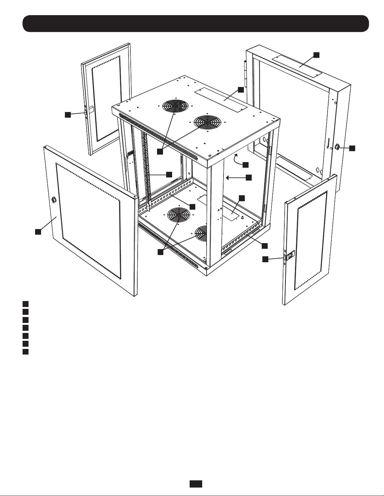
3. Feature Identification
7
5
5
2
1
Rear Door
2
Front Door
3
Horizontal Rails
4
Vertical Mounting Rails
5
Removeable Cable Access Hole Covers
6
Vents
7
Locking/Removeable Side Panels
6
3
4
3
6
4
5
3
7
1
3
Page 4
4. Enclosure Installation
Caution! Read All Instructions and Warnings Before Installation!
Warning: Rack enclosures can be extremely heavy. Do not attempt to unpack, move or install the enclosure without assistance. Use
extreme caution when handling the enclosure and be sure to follow all handling and installation instructions. Do not attempt to install
equipment without first stabilizing the enclosure.
4.1 Preparation
The enclosure must be installed in a structually sound area that is able to bear the weight of the enclosure, all the equipment that will be installed in
the enclosure and any other enclosures and/or equipment that will be installed nearby. Before unpacking the enclosure, you should transport the
shipping container closer to the final installation location to minimize the distance you will need to move the unit after the protective packaging has
been removed. If you plan to store the enclosure for an extended period before installation, follow the instructions in the Storage and Service section.
You need several tools:
• Level
• Phillips-headScrewdriver
• Appropriatetoolsforwallmounting
You also need the following hardware:
• Appropriatehardwareforwallmounting(notincluded)
4.2 Unpacking
Use at least two people to unpack the enclosure.
1
Move shipping pallet to a firm, level surface.
2
Open box and remove the four foam cormer protectors. Save all packing materials for later use unless you are certain they will not be required.
Packing materials are recyclable.
3
With one person on each side, carefully lift the enclosure out of the box and place on a firm, level surface.
4
Examine the enclosure for any damage or loose parts. Confirm all parts are present. If anything is missing or damaged, contact Tripp Lite for
assistance. Do not attempt to use the enclosure if it has been damaged.
Never extend more than one component from the enclosure at a time.
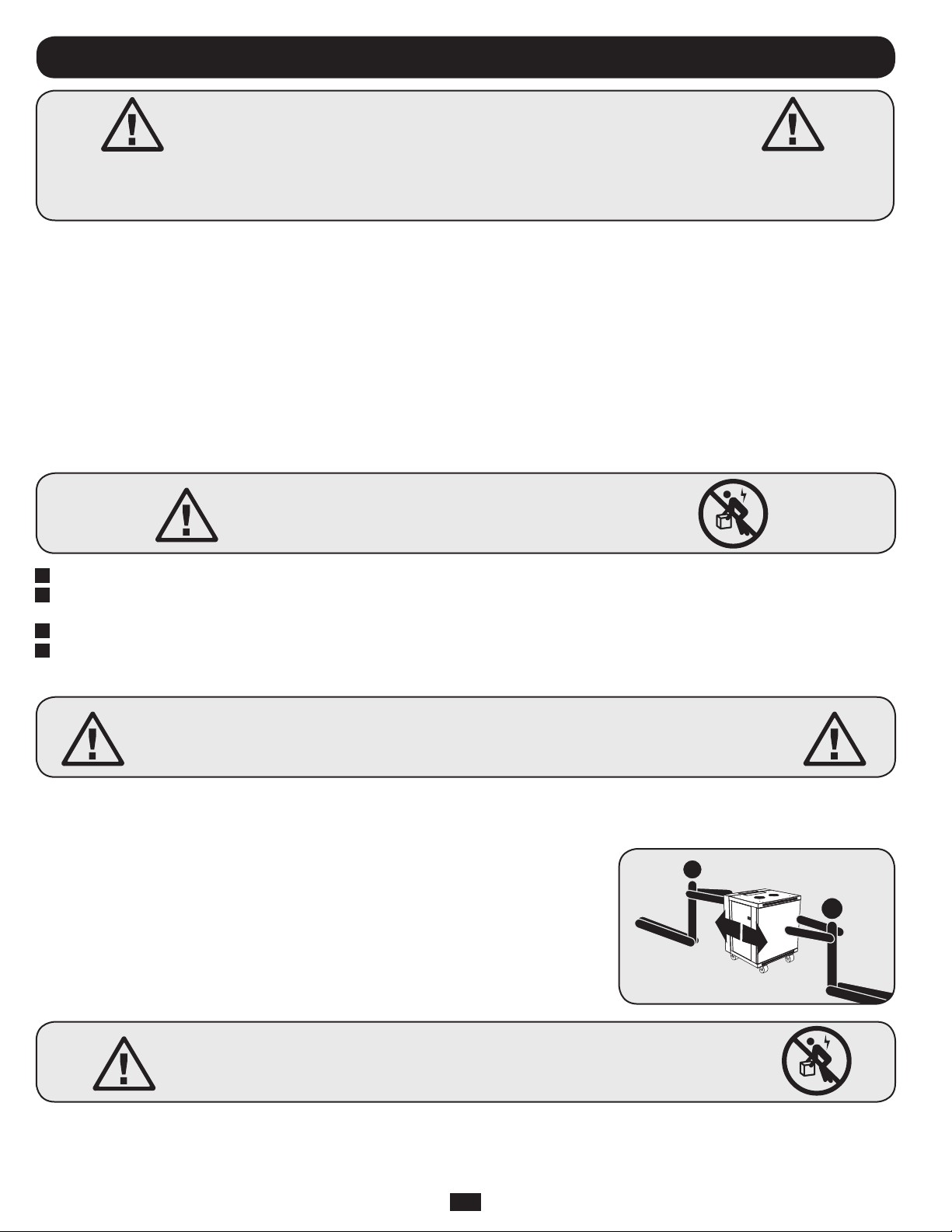
4.3 Placement
If using the optional casters, you can use the casters to move the enclosure for a short distance
over a level, smooth, stable surface by pushing it from the front or rear (not the side panels). Do
not attempt to roll the enclosure over long distances. The enclosure should be moved close to its
installation location inside its shipping container before it is unpacked. Warning: Do not push or
pull the enclosure at the side panels or pull the enclosure toward you. Only experienced
equipment operators should attempt to lift the enclosure. Use appropriate equipment and
follow all applicable safety procedures and regulations.
Warning: Never attempt to lift or install without adequate help.
Do not try lifting the enclosure alone.
4
Page 5
4. Enclosure Installation
EARTH
GROUND
(
continued
)
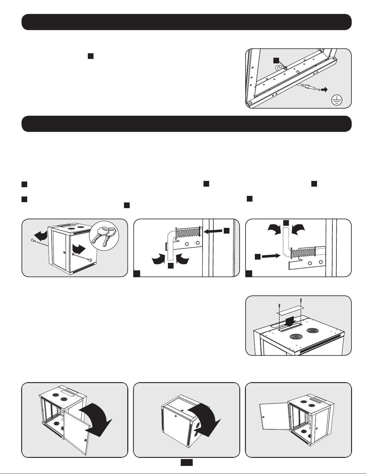
4.4 Ground Connection
All parts of the enclosure are grounded to the frame of the enclosure. Use the enclosure’s front or
rear threaded grounding point
enclosure directly to your facility’s earth ground connection with an 8 AWG (3.264 mm) wire. Route
the ground wire under the enclosure’s frame to ensure unhindered door operation. Warning:
Attach each enclosure to earth ground separately. Do not use the enclosure without an
earth ground connection.
A
and an M6 screw (included) to connect the frame of the
A
5. Enclosure Configuration
Before installation, be sure to plan the location and arrangement of components within the enclosure. Be sure all mounting rails are reversed or
adjusted for depth, depending on your equipment configuration.
5.1 Door Locks
The front and back doors have locks that are accessible by the included keys.
Each side panel locks using an L-shaped lever on the inside of the enclosure.
1
To unlock and remove the side panels, lift the shorter leg of the “L” up (labeled
on the side panel and remove it from the enclosure.
2
To re-lock the side panels, secure it in the proper position, lift the shorter leg of the “L” up (labeled
into the hole that it was in initially (labeled B). Once it is in place, push the shorter leg of the “L” down to lock it. Note: To lock and unlock the
side panels, you will need to have access to the interior of the enclosure.
A
) and pull it away from the side panel (labeled B). Pull the tab
A
) and push it toward the side panel, back
A
B
B
A
1 2
5.2 Cable Access and Management
The back door of the enclosure has a square opening for cable access and management. An
additonal opening can be found on top of the main cabinet. Each opening can also be closed by
screwing in the removeable cable access panels.
5.3 Reversing the Enclosure
In order to accommodate various rack configurations, the enclosure can be reversed. To do so, simply turn the enclosure over so that the doors open
in the opposite direction.
5
Page 6
5. Enclosure Configuration
21.362
17.125”
19.375”
14.875”
16”
16”
16”
16”
12.625”
(
continued
)
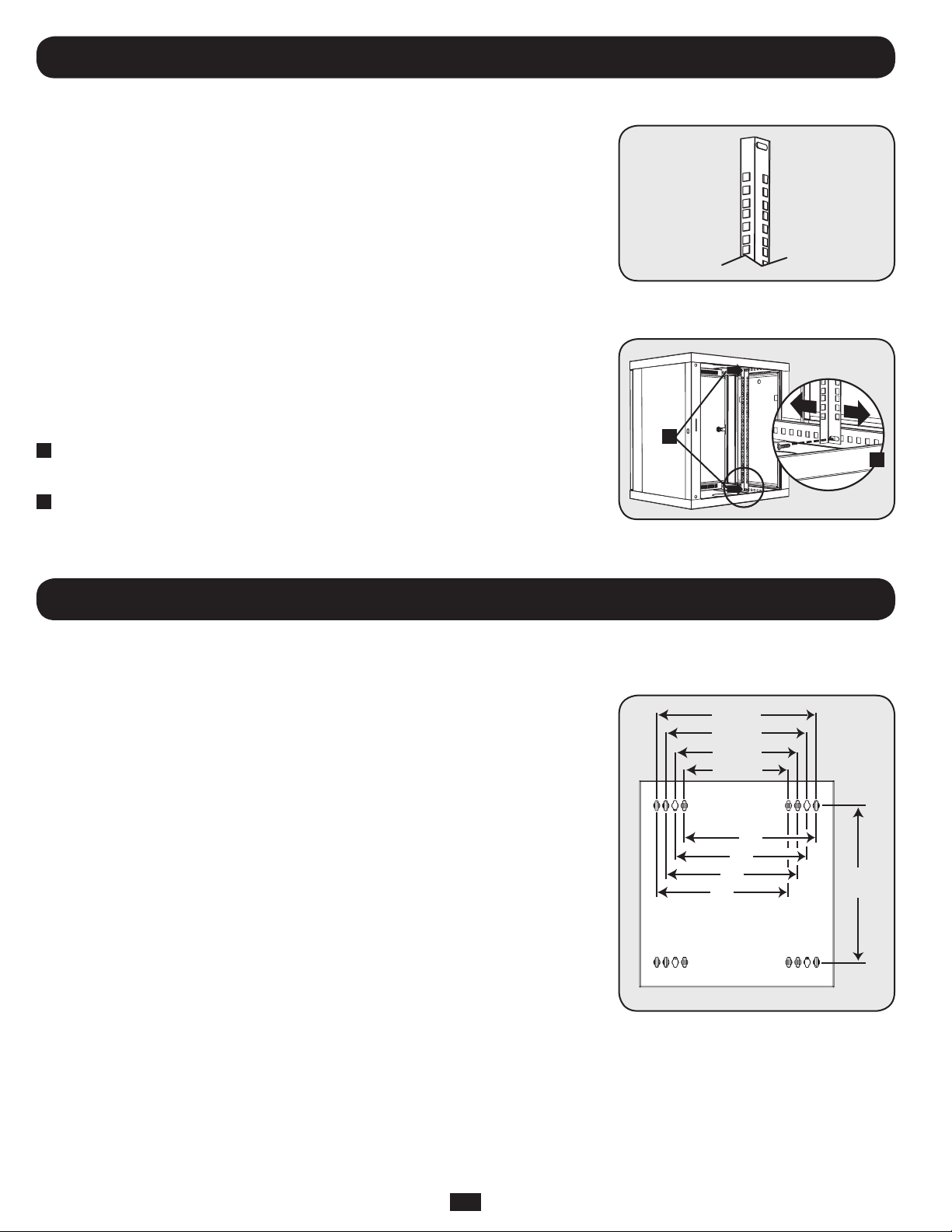
5.4 Mounting Rails
The enclosure comes with mounting rails that have square holes for mounting rack equipment. To
install equipment, use the included cage nuts and other hardware. (See page 7 for installation of
cage nuts.) Warning: Be sure to have the enclosure securely mounted to the wall, or in its
final position on the floor before mounting any equipment inside. Also be sure to have all
the right adjustments on your rails before mounting equipment. (See below for Adjusting
Mounting Rail Depth.)
5.5 Adjusting Mounting Rail Depth
Warning: Do not attempt to adjust rails while equipment is installed in the enclosure. Do
not attempt to use rails without screws installed. (2 per rail.)
The 4 mounting rails are pre-installed to accommodate equipment with a mounting depth of 20.5
inches (521 mm). Do not adjust the mounting rails unless your equipment requires a different
mounting depth. The front and rear sets of rails can be adjusted independently in 1/4-inch (6mm)
increments for mounting depths between 3 inches (76 mm) and 20.5 inches (521 mm).
1
Each rail is connected to the enclosure with 2 screws: 1 in the upper corner and another in the
lower corner. Using a Phillips-head screwdriver, remove the screws that fasten the rails to the
enclosure.
2
Slide the mounting rails to the desired depth and reattach them using the screws you removed in
Step 1.
1
2
6. Wall Mounting the Enclosure
Warning: Do not attempt to mount the enclosure to the wall with equipment mounted in the enclosure.
6.1 Mounting
There are 16 keyhole cutouts on the back door of the enclosure. Each keyhole can accommodate
an M10 or 3/8” bolt. The holes are on centers and beginning with the two innermost holes, the
centers are 12.625”, 14.875”, 17.125” and 19.375” apart, respectively moving outward and
horizontaly. Holes are then 21.362” apart vertically, as shown in the diagram.
Using a level, measure to position your mounting areas precisely. Use appropriate fasteners (not
included) to secure the enclosure to the wall. Warning: The area you plan to mount the enclosure
to must be able to withstand the weight of the enclosure and all mounted equipment. For the
weight of the enclosure and its capacity, see the specifications on page 8.
”
6
Page 7
7. Equipment Installation
20
22
21
20
22
21
20
22
21
20
22
21
24
25
26
27
28
29
23
24
25
26
27
28
29
23
4
24
1 Rack Unit
Warning: Do not install equipment until you have stabilized the enclosure. Install heavier equipment first and install it towards the bottom
of the enclosure. Install equipment starting from the bottom of the enclosure and proceeding toward the top of the enclosure - never the
reverse. If using sliding equipment rails, be careful when extending the rails. Do not extend more than one set of sliding equipment rails
at one time. Avoid extending sliding equipment rails near the top of the enclosure.
Note: The square holes in the middle of each rack unit are numbered and also include a small notch to aid identification. A single rack unit includes the space
occupied by the numbered hole and the holes directly above and below.
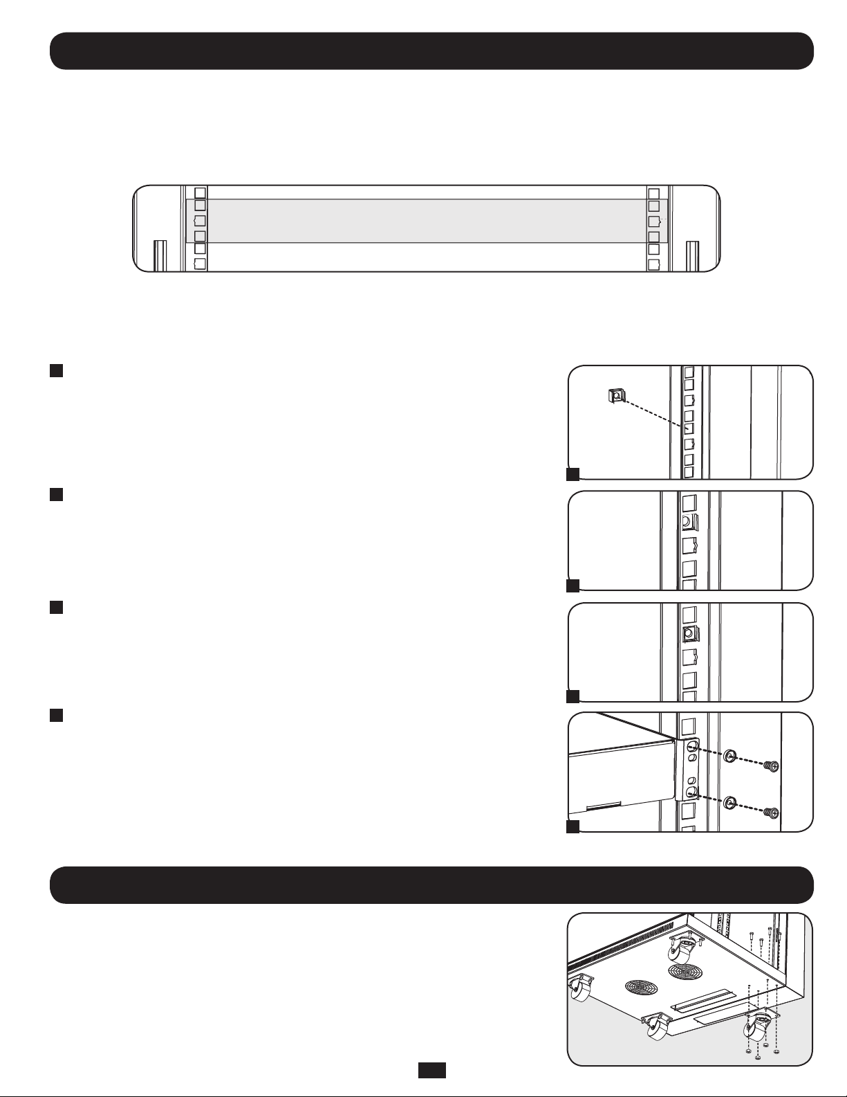
7.1 Installing or Removing Cage Nuts
WARNING: The flanges of the cage nuts should engage the sides of the square opening in the rail, not the top and bottom. Follow the
instructions in your equipment documentation to ensure proper installation of your equipment.
1
Locate the numbered square openings in the mounting rails where you plan to install your
equipment. You will install cage nuts (included) into the square openings in order to provide an
attachment point for the mounting screws (included). Note: Consult your equipment
documentation to determine how many cage nuts will be required and where they will need to
be installed.
1
2
From the inside of the mounting rail, insert one of the flanges of the cage nut through the
square opening. Press it against the side of the square opening. Each flange should engage one
side of the square opening, not the top or bottom.
2
3
Compress the cage nut at the sides slightly to allow the remaining flange to fit through the
square opening. When the cage nut is properly installed, both flanges will protrude through the
square opening and will be visible on the outer surface of the mounting rail. Repeat steps 1-3
until all required cage nuts are installed.
3
4
After installing the required cage nuts, use the included mounting screws and cup washers to
secure your equipment to the rack rail. Place the cup washers between the screws and the
equipment mounting brackets.
Note: Your equipment may also include mounting hardware. Read the mounting instructions that came
with your equipment before installing your equipment.
To Remove Cage Nuts, Reverse Steps 1-3
Note: You may wish to use a cage nut tool (user-supplied) to aid cage nut installation and removal.
8. Optional Casters
An optional caster accessory kit (Model: SRCASTER) is available separately through Tripp Lite. Go
4
to www.tripplite.com for details. The SRCASTER Kit consists of 4 casters with required locknuts and
bolts for installation. The casters install to the base of the unit using pre-drilled holes as shown in
the illustration below. For further installation instructions, refer to the manual included with the
SRCASTER Kit.
7
Page 8

9. Specifications
Model SRW12US
Dimensions (H x W x D) 25 x 23.63 x 21.6” (635 x 600 x 549 mm)
Unit Weight 60 lb (27 kg)
Load Capacity* 200 lb (90 kg) Stationary or Rolling
Mounting Depth (Adjustable) 3” to 20.5” (76 to 521 mm)
* Full wall-mount load capacity requires a mounting surface capable of bearing the full load. Rolling applications require optional SRCASTER accessory kit.
10. Storage and Service
Storage
The enclosure should be stored in a controlled indoor environment, away from moisture, temperature extremes, flammable liquids and gasses,
conductive contaminants, dust and direct sunlight. Store the enclosure in its original shipping container if possible.
Service
Your Tripp Lite product is covered by the warranty described in this manual. A variety of Extended Warranty and On-Site Service Programs are also
available from Tripp Lite. For more information on service, visit www.tripplite.com/support. Before returning your product for service, follow these steps:
1. Review the installation and operation procedures in this manual to insure that the service problem does not originate from a misreading of the
instructions.
2. If the problem continues, do not contact or return the product to the dealer. Instead, visit www.tripplite.com/support.
3. If the problem requires service, visit www.tripplite.com/support and click the Product Returns link. From here you can request a Returned Material
Authorization (RMA) number, which is required for service. This simple on-line form will ask for your unit’s model and serial numbers, along with
other general purchaser information. The RMA number, along with shipping instructions will be emailed to you. Any damages (direct, indirect, special
or consequential) to the product incurred during shipment to Tripp Lite or an authorized Tripp Lite service center is not covered under warranty.
Products shipped to Tripp Lite or an authorized Tripp Lite service center must have transportation charges prepaid. Mark the RMA number on the
outside of the package. If the product is within its warranty period, enclose a copy of your sales receipt. Return the product for service using an
insured carrier to the address given to you when you request the RMA.
11. Warranty and Warranty Registration
5-Year Limited Warranty
Seller warrants this product, if used in accordance with all applicable instructions, to be free from original defects in material and workmanship for a period of 5
years from the date of initial purchase. If the product should prove defective in material or workmanship within that period, Seller will repair or replace the
product, at its sole discretion.
THISWARRANTYDOESNOTAPPLYTONORMALWEARORTODAMAGERESULTINGFROMACCIDENT,MISUSE,ABUSEORNEGLECT.SELLERMAKESNO
EXPRESSWARRANTIESOTHERTHANTHEWARRANTYEXPRESSLYSETFORTHHEREIN.EXCEPTTOTHEEXTENTPROHIBITEDBYAPPLICABLELAW,ALLIMPLIED
WARRANTIES,INCLUDINGALLWARRANTIESOFMERCHANTABILITYORFITNESS,ARELIMITEDINDURATIONTOTHEWARRANTYPERIODSETFORTHABOVE;
ANDTHISWARRANTYEXPRESSLYEXCLUDESALLINCIDENTALANDCONSEQUENTIALDAMAGES.(Somestatesdonotallowlimitationsonhowlonganimplied
warranty lasts, and some states do not allow the exclusion or limitation of incidental or consequential damages, so the above limitations or exclusions may not
apply to you. This warranty gives you specific legal rights, and you may have other rights which vary from jurisdiction to jurisdiction).
WARNING:Theindividualusershouldtakecaretodeterminepriortousewhetherthisdeviceissuitable,adequateorsafefortheuseintended.Sinceindividual
applications are subject to great variation, the manufacturer makes no representation or warranty as to the suitability or fitness of these devices for any specific
application.
Warranty Registration
Visitwww.tripplite.com/warrantytodaytoregisterthewarrantyforyournewTrippLiteproduct.You’llbeautomaticallyenteredintoadrawingforachancetowina
FREE Tripp Lite product!*
*Nopurchasenecessary.Voidwhereprohibited.Somerestrictionsapply.Seewebsitefordetails.
Tripp Lite has a policy of continuous improvement. Specifications are subject to change without notice.
1111 W. 35th Street, Chicago, IL 60609 USA
www.tripplite.com/support
8
201203038•933117-EN
Page 9

Índice
Manual del propietario
Rack SmartRack™
para montar en pared 12U
Modelos: SRW12US & SRW12USG
1. Instrucciones de seguridad
importantes 10
2. Descripción general 10
3. Identificación de características 11
4. Instalación del rack 12
4.1 Preparación 12
4.2 Desembalaje 12
4.3 Colocación 12
4.4 Conexión a tierra 12
5. Configuración del rack 13
5.1 Cerraduras de las puertas 13
5.2 Acceso y administración de los cables 13
5.3 Inversión del rack 13
5.4 Rieles de montaje 14
5.5 Ajuste de la profundidad del riel
de montaje 14
6. Montaje del rack a la pared 14
6.1 Montaje 14
7. Instalación del equipo 15
7.1 Instalación o extracción de las
tuercas en jaula 15
8. Ruedas opcionales 15
9. Especificaciones 16
10. Almacenamiento y mantenimiento 16
11. Garantía 16
English 1
Francais 17
Русский 25
1111 W. 35th Street, Chicago, IL 60609 USA
Copyright © 2012 Tripp Lite. Todas las otras marcas registradas son propiedad de sus respectivos dueños.
www.tripplite.com/support
Page 10

1. Instrucciones de seguridad importantes
GUARDE ESTAS INSTRUCCIONES
Este manual contiene instrucciones y advertencias que deben seguirse durante la instalación y operación del producto descrito en este manual. El
incumplimiento invalidará la garantía, pudiendo causar serios daños a la propiedad y/o lesiones personales.
• Mantenga el rack en un ambiente interior controlado, lejos de la humedad, temperaturas extremas, líquidos y gases inflamables, contaminantes
conductores, el polvo y la luz directa del sol.
• Deje espacio suficiente en el frente y la parte trasera del rack para una ventilación adecuada. No bloquee, cubra ni inserte objetos en las aberturas
de ventilación externa del rack.
• El rack es extremadamente pesado. Manipúlelo con precaución. No intente desembalarlo, moverlo ni instalarlo sin ayuda. Utilice un dispositivo
mecánico como una horquilla elevadora o un gato para pálets para moverlo en el contenedor de envío.
• No coloque ningún objeto sobre el rack, especialmente contenedores de líquido, y no intente apilar los racks.
• Inspeccione el contenedor de envío y el rack para detectar daños producidos durante el transporte. No lo use si está dañado.
• Deje el rack en el contenedor de envío hasta que se lo haya movido lo más cerca posible del lugar de instalación.
• Instale el rack en un área estructuralmente sana, capaz de soportar la carga, o con piso nivelado capaz de soportar el peso del rack, de todos los
equipos que se instalarán en el rack y de cualquier otro rack y/o equipo que se instalarán cerca.
• Corte el material de embalaje con precaución. El rack podría rayarse causando daños que no están cubiertos por la garantía.
• Guarde los materiales de embalaje para utilizarlos en el futuro. Si el rack se vuelve a embalar y a enviar sin los materiales de embalaje originales,
se pueden causar daños que anularán la garantía.
• No vuelva a enviar el rack con equipos adicionales, a menos que haya sido enviado con un pálet especial contra golpes (sólo los modelos “SP1”).
El peso combinado del rack y de los equipos instalados no debe exceder la capacidad de carga del pálet. Tripp Lite no se responsabiliza por ningún
daño que se produzca durante el reenvío.
• No se recomienda el uso de este equipo en aplicaciones de mantenimiento artificial de la vida, donde se puede esperar razonablemente que su
falla cause la falla del equipo de mantenimiento de la vida o que afecte de manera importante su seguridad o eficiencia. No use este equipo en
presencia de mezclas anestésicas inflamables con aire, oxígeno u óxido nitroso.
Si instala ruedas opcionales (SRCASTER—consulte la página 15 para ver la instalación de las ruedas):
• Las ruedas están diseñadas para realizar únicamente ajustes menores de la posición dentro de la zona de instalación final. No están destinadas a
mover el rack en largas distancias.
• Cuando lo haga rodar sobre sus ruedas, empújelo siempre desde atrás, nunca hacia usted.
• Un rack rodante puede causar lesiones personales y daño a la propiedad si no se supervisa correctamente. Si es necesario hacerlo rodar por una
rampa, hágalo con precaución extrema. No intente usar rampas con una pendiente más pronunciada que 1:12.
2. Descripción general
Los racks SmartRack sirven para colocar cualquier equipo estándar para montar en rack de 19 pulgadas, independientemente del proveedor, y se
envían completamente ensamblados para una implementación rápida y fácil.
10
Page 11

3. Identificación de características
7
5
5
6
2
6
1
Puerta trasera de bloqueo
2
Puerta delantera de bloqueo/reversible
3
Rieles horizontales
4
Rieles de montaje vertical
5
Cubiertas de los orificios de acceso de cables removibles
6
Ventilaciones
7
Paneles laterales fijos/removibles
1
3
4
3
4
5
3
7
11
Page 12

4. Instalación del rack
Precaución. Lea todas las instrucciones y advertencias
antes de la instalación.
Advertencia: Los racks pueden ser extremadamente pesados. No intente desembalarlo, moverlo ni instalarlo sin ayuda. Use máxima
precaución al manipularlo y asegúrese de seguir todas las instrucciones de manipulación e instalación. No intente instalar equipos sin
estabilizar primero el rack.
4.1 Preparación
El rack se debe instalar en una zona estructuralmente sana que pueda soportar su peso, el de todos los equipos que se instalarán en él y cualquier
otro rack y/o equipos que se instalarán cerca. Antes de desembalar el rack, debería transportar el contenedor de envío lo más cerca posible de la
ubicación de instalación final para minimizar la distancia que necesitará para moverlo después de quitarle el embalaje protector. Si planea almacenarlo
durante un período prolongado antes de instalarlo, siga las instrucciones de la sección Almacenamiento y servicio.
Necesitará algunas herramientas:
• Nivel
• DestornilladorPhilips
• Herramientasadecuadasparaelmontajeenlapared
También necesita las siguientes herramientas:
• Herramientasadecuadasparaelmontajeenpared(noseincluyen)
4.2 Desembalaje
Para desempacar el gabinete, utilice al menos dos personas.
1
Mueva del pálet de envío hacia una superficie firme y nivelada.
2
Extraiga los protectores y guarde todos los materiales de embalaje para uso futuro, a menos que esté seguro de que no serán necesarios. Los
materiales de embalaje son reciclables.
3
Con una persona de cada lado, eleve el rack con cuidado hacia fuera del pálet y colóquelo en una superficie firme y nivelada.
4
Examine el rack para detectar daños o partes sueltas. Confirme que estén todas las partes. Si algo falta o está dañado, comuníquese con Tripp
Lite para obtener ayuda. No use el rack si está dañado.
Nunca extienda más de un componente del gabinete por vez.
4.3 Colocación
Si utiliza las ruedas opcionales, puede usarlas para mover el rack una distancia corta sobre una
superficie nivelada, lisa y estable empujándolo desde adelante o atrás (no desde los paneles
laterales). No intente hacerlo rodar por distancias largas. Antes de desembalarlo, el rack se debe
mover hasta cerca del sitio de instalación dentro de su contenedor de envío. Advertencia: No
empuje ni jale el gabinete por los paneles laterales ni lo jale hacia usted. Sólo operadores
de equipos experimentados deben intentar levantar el gabinete. Use los equipos
adecuados y siga todos los procedimientos y reglamentaciones de seguridad
correspondientes.
Advertencia: Nunca intente elevar o instalar el rack sin
la ayuda adecuada. No intente elevar el rack usted solo.
12
Page 13

(
TIERRA
FÍSCA
4. Instalación del rack
suite
)
4.4 Conexión a tierra
Todas las partes del rack se deben conectar a tierra al marco del rack. Use el punto roscado de
conexión a tierra del frente o de la parte trasera del gabinete
conectar el marco del gabinete directamente a la conexión a tierra de su planta con un cable
calibre 8 AWG (3.264 mm). Guíe el cable de conexión a tierra por debajo del marco del gabinete
para asegurar que las puertas funcionen libremente. Advertencia: Conecte cada rack a tierra
por separado. No use el rack sin una conexión a tierra.
A
y un tornillo M6 (incluido) para
A
5. Configuración del rack
Antes de la instalación, asegúrese de planificar la ubicación y distribución de los componentes dentro del gabinete. Asegúrese de que todos los rieles
de instalación estén al revés o ajustados según la profundidad, de acuerdo a la configuración del equipo.
5.1 Cerraduras de las puertas
Las puertas delantera y trasera tienen cerraduras accesibles con las llaves incluidas.
Cada panel lateral se asegura usando una palanca en “L” en el interior del gabinete.
1
Para desbloquear y desmontar los paneles laterales, levante la pata corta de la “L” (etiquetada
B
). Jale la trabilla en el panel lateral y desmóntelo del gabinete.
2
Para reasegurar los paneles laterales, asegúrelos en su posición correcta, levante la pata corta de la “L” (etiquetada
lateral, de nuevo al orificio donde estaba inicialmente (etiquetado B). Una vez en su sitio, oprima hacia abajo la pata corta de la “L” para
asegurarla. Nota: Para asegurar y desbloquear los paneles laterales, usted necesita tener acceso al interior del gabinete.
A
) y jale hacia afuera desde el panel lateral (etiquetado
A
) y oprímala hacia el panel
A
B
B
A
1 2
5.2 Acceso y administración de los cables
La puerta trasera del rack tiene una apertura cuadrada para el acceso y la administración de los
cables. Puede encontrarse una apertura adicional en la parte superior del gabinete principal. Cada
apertura también puede cerrarse atornillando los paneles de acceso a los cables removibles.
5.3 Inversión del rack
Para poder lograr distintas configuraciones del rack, éste puede invertirse para permitir que la puerta trasera gire en la otra dirección. Para hacerlo,
sólo gire el rack y móntelo en esta posición (consulte la siguiente sección para ver el montaje).
13
Page 14

5. Configuración del rack
21.362
17.125”
19.375”
14.875”
16”
16”
16”
16”
12.625”
(continuación)
5.4 Rieles de montaje
El rack viene con rieles de montaje que poseen orificios cuadrados para montar los equipos del
rack. Para instalar los equipos, utilice las tuercas de jaula y las otras herramientas incluidas.
(Consulte la página 15 para ver la instalación de las tuercas de jaula). Advertencia: Asegúrese
de que el rack quede montado firmemente a la pared, o en su posición final en el piso
antes de montar cualquier equipo en el interior. Asegúrese también de realizar todos los
ajustes adecuados de rieles antes de montar los equipos. (Consulte la sección siguiente
para ver el Ajuste de la profundidad del riel de montaje).
5.5 Ajuste de la profundidad del riel de montaje
Advertencia: No intente ajustar los rieles mientras los equipos están instalados en el rack.
No intente utilizar rieles sin tornillos instalados. (2 por riel).
Los 4 rieles de montaje están preinstalados para acomodar los equipos con una profundidad de
montaje de 20,5 pulgadas (521 mm). No ajuste los rieles de montaje a menos que los equipos
requieran una profundidad de montaje distinta. Los conjuntos de rieles frontales y traseros pueden
ajustarse en forma independiente para montaje equipos con profundidades de montaje de montaje
de entre 3 pulgadas (76 mm) y 20,5 pulgadas (521 mm).
1
Cada riel se conecta al rack con dos tornillos: 1 en la esquina superior y otro en la esquina
inferior. Utilizando un destornillador Phillips, extraiga los tornillos que ajustan los rieles al rack.
2
Deslice los rieles de montaje hasta la profundidad deseada y vuelva a unirlos mediante los
tornillos que extrajo anteriormente en el Paso 1.
1
2
6. Montaje del rack a la pared
Advertencia: No intente montar el rack en la pared con equipos montados en el rack.
6.1 Montaje
Existen 16 orificios perforados en la parte trasera del gabinete. Cada orificio está adaptado para
insertar un tornillo M10 ó de 3/8". Los orificios están en los centros e inician con los dos orificios
más internos, los centros están separados a 12.625”, 14.875”, 17.125” y 19.375” entre sí,
desplazándose respectivamente hacia afuera y horizontalmente. Los orificios están separados
verticalmente a 21.362" (542.6 mm), como se muestra en el diagrama.
Utilizando un nivel, mida la posición de las áreas de montaje en forma precisa. Utilice pasadores
adecuados (no incluidos) para asegurar el rack a la pared. Advertencia: Las herramientas que
planea utilizar y el área en donde planea montar el rack deben poder soportar el peso del
rack y de todos los equipos montados. Para ver el peso del rack y su capacidad, consulte
las Especificaciones en la página 16.
”
14
Page 15

7. Instalación del equipo
20
22
21
20
22
21
20
22
21
20
22
21
24
25
26
27
28
29
23
24
25
26
27
28
29
23
4
24
1 Unidad de Rack
Advertencia: No instale equipos hasta que haya estabilizado el rack. Instale primero los equipos más pesados en la parte inferior del
rack. Instálelos de abajo hacia arriba, nunca en sentido contrario. Si usa rieles para equipos deslizantes, tenga cuidado al extender los
rieles. No extienda más de un juego de rieles por vez. Evite extender rieles de equipos deslizantes cerca de la parte superior del rack.
Nota: Los orificios cuadrados en el centro de cada unidad del rack están numerados y también incluyen una pequeña muesca para identificarlos. Una sola
unidad de rack incluye el espacio ocupado por el orificio numerado y los orificios ubicados directamente encima y debajo.
7.1 Instalación o extracción de las tuercas de jaula
ADVERTENCIA: Las bridas de las tuercas en jaula deben engancharse en los lados de la abertura cuadrada del riel, no en la parte
superior o inferior. Siga las instrucciones de la documentación de sus equipos para instalarlos correctamente.
1
Ubique las aberturas cuadradas numeradas en los rieles de montaje en donde planea instalar
los equipos. Instalará tuercas en jaula (incluidas) en las aberturas cuadradas para obtener un
punto de fijación para los tornillos de montaje (incluidos). Nota: Consulte la documentación de
su equipo para determinar cuántas tuercas en jaula necesitará y dónde debe instalarlas.
1
2
Desde la parte interior del riel de montaje, inserte una de las bridas de la tuerca de jaula a
través de la abertura cuadrada. Presiónela contra el lado de la abertura cuadrada. Cada brida
debe engancharse en un lado de la abertura cuadrada, ni arriba ni abajo.
2
3
Apriete la tuerca de jaula por los costados suavemente, para permitir que la brida restante
encaje a través de la abertura cuadrada. Cuando la tuerca de jaula esté instalada
adecuadamente, ambas bridas asomarán a través de la abertura cuadrada y podrán verse
desde la superficie exterior del riel de montaje. Repita los pasos 1 a 3 hasta que todas las
tuercas en jaula estén instaladas.
3
4
Después de instalar las tuercas en jaula necesarias, utilice los tornillos de montaje y las
arandelas incluidos para asegurar los equipos al riel del rack. Coloque las arandelas entre los
tornillos y los soportes de montaje del equipo.
Nota: Su equipo también puede incluir herramientas de montaje. Lea las instrucciones de montaje de su
equipo antes de instalarlo.
Para extraer las tuercas en jaula, siga los pasos 1 a 3 en sentido inverso
Nota: Puede usar una herramienta para tuercas en jaula (suministrada por el usuario) para ayudarse en
la instalación y extracción
4
8. Ruedas opcionales
Se dispone de un kit de accesorios de ruedas (Modelo: SRCASTER) que puede adquirir por
separado a través de Tripp Lite. Visite www.tripplite.com para obtener detalles. El kit SRCASTER Kit
se compone de 4 ruedas con las contratuercas y pernos adecuados para la instalación. Las ruedas
se instalan en la base de la unidad a través de los orificios taladrados ubicados cerca de cada una
de las esquinas de la parte inferior de la unidad. Para obtener instrucciones de instalación
adicionales, consulte el manual incluido con el kit SRCASTER.
15
Page 16

9. Especificaciones
Modelo SRW12US & SRW12USG
Dimensiones (A x A x P) 25 x 23.6 x 21.6" (638 x 600 x 851 mm)
Peso de la unidad 60 lb (27 kg)
Capacidad de carga* 200 lb (90 kg) estacionaria o rodante
Profundidad de montaje (ajustable) 3" a 20.5" (76 a 521 mm)
* La capacidad de carga total para montar en pared requiere una superficie de montaje capaz de soportar toda la carga. Las aplicaciones rodantes requieren el kit de accesorios
SRCASTER opcional.
10. Almacenamiento y servicio
Almacenamiento
El rack debe almacenarse en un ambiente interior controlado, lejos de la humedad, temperaturas extremas, líquidos y gases inflamables,
contaminantes conductores, polvo y luz solar directa. Si es posible, almacénelo en su contenedor de envío original.
Mantenimiento
Su producto Tripp Lite está cubierto por la garantía descrita en este manual. Tripp Lite también pone a su disposición una variedad de Garantías
extendidas y Programas de servicio técnico en el sitio. Si desea más información sobre el servicio técnico, visite www.tripplite.com/support. Antes de
devolver su producto para servicio técnico, siga estos pasos:
1. Revise la instalación y los procedimientos de operación que se encuentran en este manual para asegurarse de que el problema de servicio no se
debe a una mala lectura de las instrucciones.
2. Si el problema persiste, no se comunique ni devuelva el producto al mayorista. En cambio, visite www.tripplite.com/support.
3. Si el problema exige servicio técnico, visite www.tripplite.com/support y haga clic en el enlace Devoluciones de productos. Desde aquí puede
solicitar un número de Autorización de Material Devuelto (RMA), que se necesita para el servicio técnico. En este sencillo formulario en línea se le
solicitarán los números de serie y modelo de la unidad, junto con otra información general del comprador. El número RMA y las instrucciones para
el envío se le enviarán por correo electrónico. La presente garantía no cubre ningún daño (directo, indirecto, especial o consecuencial) del producto
que ocurra durante el envío a Tripp Lite o a un centro de servicio técnico de Tripp Lite autorizado. Los productos enviados a Tripp Lite o a un centro
de servicio técnico de Tripp Lite autorizado deben tener prepagos los cargos de transporte. Escriba el número RMA en el exterior del embalaje. Si el
producto se encuentra dentro del período de garantía, adjunte una copia de su recibo de venta. Envíe el producto para servicio técnico mediante un
transportador asegurado a la dirección que se le proporcionó cuando solicitó el número RMA.
11. Garantía
Garantía limitada por 5 años
El vendedor garantiza que este producto no tiene defectos originales de materiales ni de mano de obra por un período de cinco años a partir de la
fecha original de compra, si se utiliza de acuerdo con todas las instrucciones correspondientes. En caso de demostrarse dentro de ese período que el
producto tiene defectos de materiales o de mano de obra, el vendedor lo reparará o reemplazará a su exclusiva discreción.
ESTA GARANTÍA NO CUBRE EL DESGASTE NORMAL NI LOS DAÑOS CAUSADOS POR ACCIDENTES, MAL USO, ABUSO O NEGLIGENCIA. EL VENDEDOR
NO OFRECE NINGUNA GARANTÍA EXPRESA QUE NO SEA LA ESTABLECIDA EXPRESAMENTE EN EL PRESENTE DOCUMENTO. EXCEPTO EN LA MEDIDA
ENQUELOPROHÍBANLASLEYESAPLICABLES,LADURACIÓNDETODASLASGARANTÍASIMPLÍCITAS,INCLUIDASLASDECOMERCIABILIDADO
APTITUD,SELIMITAALPERÍODODEGARANTÍAANTESMENCIONADOYESTAGARANTÍAEXCLUYEEXPRESAMENTETODOSLOSDAÑOSINCIDENTALES
E INDIRECTOS. (Algunos Estados no permiten las limitaciones a la duración de una garantía implícita y otros Estados no permiten la exclusión o
limitación de los daños incidentales o indirectos, de modo que las limitaciones o exclusiones antes mencionadas pueden no corresponder en su caso.
Esta garantía le otorga derechos legales específicos y usted puede tener otros derechos que varían de una jurisdicción a otra).
ADVERTENCIA: Antes de usar este dispositivo, cada usuario debe ocuparse de determinar si es apto, adecuado o seguro para el uso que pretende
darle. Dado que las aplicaciones individuales están sujetas a diversas variaciones, el fabricante no representa ni garantiza la idoneidad o condición de
estos dispositivos para cualquier aplicación específica.
Tripp Lite tiene la política de mejora continua. Las especificaciones están sujetas a cambios sin notificación previa.
1111 W. 35th Street, Chicago, IL 60609 USA
www.tripplite.com/support
16
201203038•933117-ES
Page 17

Guide du propriétaire
Enceinte SmartRack™
12U fixée au mur
Table des matières
Modèle: SRW12US & SRW12USG
1. Importantes consignes de sécurité 18
2. Vue d’ensemble 18
3. Identification des caractéristiques 19
4. Installation de l’armoire 20
4.1 Préparation 20
4.2 Déballage 20
4.3 Mise en place 20
4.4 Mise à la terre 21
5. Configuration de l’armoire 21
5.1 Serrures de portes 21
5.2 Accès et gestion de câble 21
5.3 Renversement de l’enceinte 21
5.4 Rails de fixation 22
5.5 Réglage de la profondeur
du rail de fixation 22
6. Montage de l’enceinte au mur 22
6.1 Montage 22
7. Installation de l’équipement 23
7.1 Installation ou enlèvement
des écrous à cage 23
8. Roulettes facultatives 23
9. Caractéristiques techniques 24
10. Entreposage et entretien 24
11. Garantie 24
English 1
Español 9
Русский 25
1111 W. 35th Street, Chicago, IL 60609 USA
Copyright © 2012 Tripp Lite. Toutes les marques de commerce appartiennent à leurs propriétaires respectifs.
www.tripplite.com/support
Page 18

1. Importantes consignes de sécurité
SAUVEGARDER CES DIRECTIVES
Ce manuel contient les directives et les mises en garde qui doivent être suivies pendant l’installation et l’utilisation du produit décrit dans ce manuel.
Tout manque de se conformer aux directives peut annuler la garantie et entraîner des dégâts matériels ou des blessures corporelles.
• Maintenir l’armoire dans un environnement intérieur contrôlé, à l’abri de l’humidité, des températures extrêmes, des liquides et des gaz
inflammables, de contaminants conducteurs, de la poussière et de la lumière directe du soleil.
• Laisser un espace suffisant à l’avant et à l’arrière de l’armoire pour garantir une bonne circulation d’air. Ne pas bloquer, couvrir ou introduire des
objets dans les ouvertures externes de ventilation de l’armoire.
• Cette armoire est très lourde. Faire attention lors de la manutention de l’armoire. Ne pas essayer de la déballer, de la déplacer ou de l’installer sans
aide. Utiliser un appareil mécanique comme un chariot élévateur ou une transpalette à main pour déplacer l’armoire dans le conteneur
d’expédition.
• Ne poser aucun objet sur l’armoire, en particulier des contenants de liquide, et ne pas essayer d’empiler les armoires.
• Inspecter le conteneur d’expédition et l’armoire pour vérifier si elle a été endommagée lors de l’expédition. Ne pas utiliser l’armoire si elle a été
endommagée.
• Laisser l’armoire dans le conteneur d’expédition pour la déplacer aussi près que possible de l’emplacement final de l’installation.
• Installer l’armoire dans une aire à structure solide dont le plancher de niveau est capable de supporter le poids de l’armoire, de tout l’équipement
qui sera installé dans l’armoire et des autres armoires et équipements qui seront installés à proximité.
• Faire attention lors de la coupe des matériaux d’emballage. L’armoire pourrait être égratignée, entraînant des dommages non couverts par la
garantie.
• Conserver tous les matériaux d’emballage pour une future utilisation. Réemballer et expédier l’armoire sans son emballage original pourrait causer
des dommages qui annuleraient la garantie.
• Ne pas réexpédier l’armoire avec de l’équipement supplémentaire sauf si elle a été expédiée avec une palette antichoc spéciale (Modèle « SP1 »
uniquement). Le poids combiné de l’armoire et de l’équipement installé ne doit pas dépasser la capacité de charge de la palette. Tripp Lite n’est
pas responsable des dommages ayant lieu durant une réexpédition.
• Il est déconseillé d’utiliser cet équipement dans des applications médicales où une panne de cet équipement pourrait normalement provoquer la
panne de l’équipement de survie ou altérer notablement sa sécurité ou son efficacité. Ne pas utiliser cet équipement en présence d’un mélange
anesthétique inflammable avec de l’air, de l’oxygène ou de l’oxyde nitreux.
Pour l’installation de roulettes facultatives (SRCASTER-voir page 7 pour l’installation de roulette) :
• Les roulettes ne sont pas conçues pour fournir un support de l’enceinte à long terme après installation finale. Les roulettes sont uniquement
conçues pour des ajustements de position moins importants au lieu final d’installation. Les roulettes ne sont pas conçues pour déplacer l’enceinte
sur de longues distances.
• Ne pas pousser sur les panneaux latéraux de l’armoire pour la déplacer. Procéder ainsi causera un risque de basculement.
• Lors d’un déplacement de l’armoire sur ses roulettes, toujours pousser de l’arrière, ne jamais tirer vers soi.
• Un déplacement sur roulettes mal surveillé de l’armoire peut causer des blessures ou des dégâts matériels. Faire très attention s’il faut faire
descendre une rampe d’accès à l’armoire sur roulettes. Ne pas essayer d’utiliser des rampes d’accès avec une pente plus raide que 1 : 12.
2. Vue d’ensemble
Les armoires de stockage SmartRack peuvent recevoir tous les équipements standard de 19 po pour montage en bâti, quelque soit le fournisseur, et
sont expédiées entièrement montées pour une mise en place rapide et facile.
18
Page 19

3. Identification des caractéristiques
7
5
5
2
1
Porte arrière
2
Porte avant
3
Rails horizontaux
4
Rails de fixation verticaux
5
Couvercles amovibles d’ouverture d’accès de câble
6
Évents
7
Panneaux latéraux amovibles/verrouillables
6
3
4
3
6
4
5
3
7
1
19
Page 20

4. Installation de l’armoire
Attention! Lire toutes les instructions et les mises
en garde avant l’installation!
Avertissement : Les enceintes d’armoire peuvent être extrêmement lourdes. Ne pas essayer de déballer, de déplacer ou d’installer
l’enceinte sans aide. Faites très attention en manipulant l’enceinte et assurez-vous de suivre toutes les instructions de manutention et
d’installation. Ne pas essayer d’installer le matériel sans d’abord stabiliser l’enceinte.
4.1 Préparation
Il faut installer l’armoire dans une aire à structure solide dont le plancher de niveau est capable de supporter le poids de l’armoire, de tout
l’équipement qui sera installé dans l’armoire et des autres armoires et équipements qui seront installés à proximité. Avant de déballer l’armoire, vous
devez transporter le conteneur d’expédition à proximité de l’emplacement de l’installation finale pour réduire la distance de déplacement de l’appareil
une fois que l’emballage protecteur aura été enlevé. Si vous planifiez d’entreposer l’armoire pendant une période prolongée avant installation, suivre
les instructions du chapitre Entreposage et service.
Vous avez besoin de plusieurs outils :
• Niveauàbulle
• Tournevispourviscruciforme
• Outilsappropriéspourlemontageaumur
4.2 Déballage
Vous avez également besoin du matériel suivant :
• Matérielappropriépourfixationmurale(noninclus)
Employer au moins deux personnes pour déballer l’enceinte.
1
Déplacer la palette d’expédition à une surface solide et bien nivelée.
2
Ouvrirlaboîteetenleverlesquatrecornièresdeprotectionenmousse.Sauvegardertouslesmatériauxd’emballagepourl’usageultérieuràmoins
que vous soyez certain qu’ils ne seront pas exigés. Les matériaux d’emballage sont recyclables.
3
Avec une personne de chaque côté, soulever soigneusement l’enceinte hors de la boîte et la placer sur une surface solide bien nivelée.
4
Examiner l’enceinte à la recherche de dommages ou de pièces desserrées. Confirmer que toutes les pièces sont présentes. Si quelque chose
manque ou est endommagée, contacter Tripp Lite pour de l’aide. Ne pas essayer d’utiliser l’enceinte si elle a été endommagée.
Ne jamais étendre plus d’un composant de l’enceinte à la fois.
4.3 Mise en place
Si vous utilisez les roulettes facultatives, vous pouvez les utiliser pour déplacer l’enceinte sur une
courte distance sur une surface stable, lisse et nivelée en la poussant de l’avant ou de l’arrière
(pas par les panneaux latéraux). Ne pas essayer de rouler l’enceinte sur de longues distances.
L’enceinte devrait être déplacée près de son lieu d’installation à l’intérieur de son conteneur
d’expédition avant qu’elle ne soit déballée. Avertissement : Ne pas pousser ou tirer l’enceinte
aux panneaux latéraux et ne pas tirer l’enceinte vers vous. Seuls les conducteurs de
matériel expérimentés devraient essayer de soulever l’enceinte. Utiliser le matériel
approprié et suivre toutes les procédures et tous les règlements de sûreté applicables.
Avertissement : Ne jamais essayer de soulever ou d’installer
sans l’aide appropriée. Ne pas essayer de soulever l’enceinte
sans l’aide d’une autre personne au moins.
20
Page 21

4. Installation d’enceinte (suite)
EARTH
GROUND
4.4 Mise à la terre
Toutes les pièces de l’enceinte sont mises à la terre au châssis de l’enceinte. Utiliser la prise de
masse filetée avant ou arrière de l’enceinte
l’enceinte directement à la prise de terre au sol de votre lieu d’installation avec un fil de 8 A.W.G.
(3,264 mm). Faire passer le fil de masse sous le châssis de l’enceinte pour assurer le
fonctionnement de la porte sans difficulté. Avertissement : Attacher chaque enceinte à la terre
séparément. Ne pas utiliser l’enceinte sans prise de terre au sol.
et une vis M6 (incluse) pour brancher le châssis de
A
A
PRISE DE
TERRE
5. Configuration de l’armoire
Avant installation, assurez-vous de préparer le lieu et l’agencement des composants dans l’enceinte. Assurez-vous que tous les rails de fixation sont
inversés ou réglés à la profondeur, selon la configuration de votre matériel.
5.1 Serrures de portes
Les portes avant et arrière ont des serrures qui sont accessibles par les touches inclus.
Chaque panneau latéral serrures utilisant un levier en L à l'intérieur de l'enceinte.
1
Pour déverrouiller et de retirer les panneaux latéraux, soulevez la jambe plus courte du "L" vers le haut (
languette sur le panneau latéral et le retirer de l'enceinte.
2
Pour re-verrouiller les panneaux latéraux, le sécuriser dans la bonne position, soulevez la jambe plus courte du "L" vers le haut (
vers le panneau latéral, dans le trou qu'il était dans un premier temps (B). Une fois qu'il est en place, poussez le jambe plus courte du «L» afin de
la verrouiller. Remarque: Pour verrouiller et déverrouiller les panneaux latéraux, vous aurez besoin d'avoir accès à l'intérieur de l'enceinte.
A
) et retirez-le panneau latéral (B). Tirez la
A
) et le pousser
A
B
B
A
1 2
5.2 Accès et gestion de câble
La porte arrière de l’enceinte a une ouverture carrée pour l’accès et la gestion de câble. Une
ouverture supplémentaire peut être trouvée au-dessus de l’armoire principale. Chaque ouverture
peut également être fermée en vissant les panneaux d’accès de câble amovibles.
5.3 Renversement de l’enceinte
Afin d’adapter diverses configurations d’armoire, l’enceinte peut être inversée. Pour cela, faire tourner tout simplement l’enceinte de sorte que les
portes s’ouvrent dans le sens opposé.
21
Page 22

5. Configuration d’enceinte (suite)
21.362
17.125”
19.375”
14.875”
16”
16”
16”
16”
12.625”
5.4 Rails de fixation
L’enceinte arrive accompagnée de rails de fixation qui ont des trous rectangulaires pour le montage
du matériel d’armoire. Pour installer le matériel, utiliser les écrous à cage ainsi que d’autres
ferrures. (Voir page 7 pour l’installation des écrous à cage.) Avertissement : Assurez-vous de
monter l’enceinte solidement au mur, ou en sa position finale sur le sol avant de monter
n’importe quel matériel à l’intérieur. Assurez-vous également d’avoir tous les réglages
corrects sur vos rails avant de monter le matériel. (Voir ci-dessous pour régler la
profondeur du rail de fixation.)
5.5 Réglage de la profondeur du rail de fixation
Avertissement : Ne pas essayer de régler les rails alors que du matériel est installé dans
l’enceinte. Ne pas essayer d’utiliser des rails sans vis installées. (2 par rail.)
Les 4 rails de fixation sont préinstallés pour s’adapter au matériel avec une profondeur de fixation
de 20,5 pouces (521 mm). Ne pas régler les rails de fixation à moins que votre matériel n’exige
une profondeur de fixation différente. Les ensembles de rails avant et arrière peuvent être réglés
indépendamment en incréments d’1/4 de pouce (6mm) aux profondeurs de fixation entre 3
pouces (76 mm) et 20,5 pouces (521 mm).
1
Chaque rail est attaché à l’enceinte à l’aide de 2 vis. 1 dans le coin supérieur et une autre au
coin inférieur. En utilisant un tournevis pour vis cruciforme, enlever les vis qui attachent les rails
à l’enceinte.
2
Glisser les rails de fixation à la profondeur désirée et les rattacher à l’aide des vis que vous avez
enlevées dansl’étape 1.
1
2
6. Montage de l’enceinte au mur
Avertissement : Ne pas essayer de monter l’enceinte au mur alors que le matériel est installé dans l’enceinte.
6.1 Montage
Il y a 16 fentes en forme de trou de serrure sur la porte arrière de l’enceinte. Chaque trou de
serrure peut accueillir un boulon M10 ou 3/8”. Les fentes sont aux centres et en commençant par
les deux trous les plus centraux, les centres sont 12,625 pouces (320,67 mm), 14,875 pouces
(377,82 mm), 17,125 pouces (434,97 mm) et 19,375 pouces (492,12 mm) à part,
respectivement en allant vers l’extérieur et horizontalement. Les trous sont alors à l’écart
verticalement d’une distance de 21,362 pouces (542,60 mm) comme montré sur le diagramme.
A l’aide d’un niveau à bulle, mesurer pour situer vos zones de montage avec précision. Utiliser les
dispositifs de fixation appropriés (non inclus) pour fixer l’enceinte au mur. Avertissement :
L’endroit où vous prévoyez de monter l’enceinte au doit pouvoir supporter le poids de
l’enceinte et de tout le matériel qui y est installé. Pour le poids de l’enceinte ainsi que sa
capacité voir les caractéristiques en page 8.
”
22
Page 23

7. Installation de l’équipement
20
22
21
20
22
21
20
22
21
20
22
21
24
25
26
27
28
29
23
24
25
26
27
28
29
23
2424
1 Rack Unit
MISE EN GARDE : Ne pas installer d’équipement avant d’avoir stabilisé l’armoire. Installer d’abord l’équipement lourd et à la base de
l’armoire. Installer l’équipement en commençant à la base de l’armoire vers son sommet - jamais l’inverse. Si vous utilisez des rails
glissières, faire attention lors de l’extension des rails. Ne pas ouvrir plus d’un jeu de rails glissières en même temps. Éviter d’ouvrir un jeu
de rails glissières près du sommet de l’armoire.
Remarque : Les trous carrés au milieu de chaque division de bâti sont numérotés et disposent aussi d’une petite encoche pour aider à l’identification. Une
seule division de bâti comprend l’espace occupé par le trou numéroté et les trous immédiatement au dessus et au dessous.
1 division de bâti
7.1 Installation ou enlèvement des écrous à cage
MISE EN GARDE : Les brides des écrous à cage doivent s’encastrer dans les côtés de l’ouverture carrée dans le rail, pas au sommet ni à
la base. Suivre les instructions de la documentation de votre équipement pour garantir sa bonne installation.
1
Repérer les ouvertures carrées numérotées dans les profilés de montage où vous planifiez
d’installer votre équipement. Vous poserez des écrous à cage (fournis) dans les ouvertures
carrées afin de fournir un point de fixation pour les vis de montage (fournies). Remarque :
Consulter la documentation de votre équipement pour savoir combien d’écrous à cage seront
nécessaires et où ils devront être installés.
2
Depuis l’intérieur du profilé de montage, introduire une des brides de l’écrou à cage dans
l’ouverture carrée. Appuyer la bride contre le côté de l’ouverture. Chaque bride doit s’encastrer
dans un des côtés de l’ouverture, pas au sommet ni à la base.
3
Comprimer légèrement les côtés de l’écrou à cage pour permettre à l’autre bride de s’engager
dans l’ouverture. Quand l’écrou à cage est correctement posé, les deux brides vont dépasser de
l’ouverture carrée et seront visibles à la surface extérieure du profilé de montage. Répéter les
étapes 1 à 3 jusqu’à ce que tous les écrous à cage nécessaires soient posés.
4
Après la pose des écrous à cage, utiliser les vis de montage et les rondelles à collerette pour
fixer l’équipement au profilé du bâti. Placer les rondelles à collerette entre les vis et les pattes
de fixation de l’équipement.
Remarque : La quincaillerie de fixation peut aussi être jointe à votre équipement. Lire les instructions de
montage jointes à votre équipement avant d’installer celui-ci.
Pour enlever les écrous à cage, inverser les étapes 1 à 3
Remarque : Vous pouvez utiliser un outil pour écrou à cage (fourni par l’utilisateur) afin d’aider à la
pose et à l’enlèvement des écrous.
1
2
3
4
8. Roulettes facultatives
Un kit de roulettes optionnel (modèle : SRCASTER) est disponible séparément chez Tripp Lite.
Visiter www.tripplite.com pour plus de détails. Le kit SRCASTER se compose de 4 roulettes avec les
contre-écrous et les boulons nécessaires pour l’installation. Les roulettes s’installent sur la base de
l’unité utilisant les avant-trous comme indiqué sur l’illustration ci-dessous. Pour des instructions
d’installation supplémentaires, se référer au manuel inclus avec le kit SRCASTER.
23
Page 24

9. Caractéristiques techniques
Modèle SRW12US
Dimensions (H x L x P) 25 x 23,63 x 21,6” (635 x 600 x 549 mm)
Poids unitaire 60 livres (27 kg)
Capacité nominale* 200 livres (90 kg) Immobile ou En mouvement
Profondeur de fixation (Réglable) 3” à 20,5” (76 à 521 mm)
* Une installation murale complète nécessite une surface de support capable de soutenir le poids total du dispositif. La trousse accessoire SRCASTER est disponible en option pour les
applications montées sur roues.
10. Entreposage et entretien
Entreposage
Cette armoire doit être entre poser dans un environnement intérieur contrôlé, à l’abri de l’humidité, des températures extrêmes, des liquides et des
gaz inflammables, de contaminants conducteurs, de la poussière et de la lumière directe du soleil. Entreposer l’armoire dans son conteneur
d’expédition original si possible.
Service
Votre produit Tripp Lite est couvert par la garantie décrite dans ce manuel. Une variété de garantie prolongées et de programmes de service sur place
sont également disponibles chez Tripp Lite. Pour plus de renseignements sur le service, visitez www.tripplite.com/support. Avant de retourner votre
produit pour entretien ou réparation, suivez les étapes suivantes :
1. Relisez les directives d’installation et de fonctionnement de ce manuel afin de vous assurer que le problème n’a pas pour origine une mauvaise
lecture des directives.
2. Si le problème persiste, ne pas communiquer ou renvoyer le produit au vendeur. À la place, visitez www.tripplite.com/support.
3. Si le problème nécessite une réparation, visitez www.tripplite.com/support et cliquez sur le lien Product Returns (retour du produit). De cet endroit,
vous pouvez demander un numéro d’autorisation de retour de matériel (RMA) qui est exigé pour une réparation. Ce formulaire en ligne simple vous
demandera le numéro de modèle et le numéro de série de votre unité ainsi que d’autres renseignements généraux concernant l’acheteur. Le
numéro RMA, ainsi que les instructions concernant le transport vous seront acheminées par courriel. Tout dommage (direct, indirect, spécial ou
fortuit) survenu au produit pendant le transport à Tripp Lite ou à un centre de service autorisé Tripp Lite est exclu de la garanti. Les produits expédiés
à Tripp Lite ou à un centre de service autorisé doivent être prépayés. Inscrire le numéro RMA sur le paquet. Si le produit est encore couvert par la
garantie de deux ans, joindre une copie de votre facture d’achat. Retourner le produit pour réparation par un transporteur assuré à l’adresse qui
vous a été donnée lorsque vous avez demandé le RMA.
11. Garantie
Garantie limitée de 5 ans.
Le vendeur garantit que, s’il a été utilisé selon les directives applicables, ce produit est exempt de tout défaut initial de matériel et de fabrication pendant une
période de 5 ans à dater de l’achat initial. Si le produit s’avère défectueux sur le plan matériel ou de la fabrication durant cette période, le vendeur le réparera
ou le remplacera, gratuitement.
CETTEGARANTIENES’APPLIQUEPASÀL’USURENORMALEOUAUXDOMMAGESDUSÀUNACCIDENT,UNEMAUVAISEUTILISATION,UNABUSOUUNE
NÉGLIGENCE.LEVENDEURN’ACCORDEAUCUNEGARANTIEEXPRESSEAUTREQUECELLECONTENUEDANSLESDISPOSITIONSCI-DESSUS.SAUF
DISPOSITIONSCONTRAIRESPRÉVUESPARLALOI,TOUTESLESGARANTIESIMPLICITES,YCOMPRISLESGARANTIESDEQUALITÉCOMMERCIALEET
D’ADAPTATIONÀUNUSAGEPARTICULIER,SONTLIMITÉESÀLAPÉRIODEDEGARANTIEPRÉCITÉE.CETTEGARANTIEEXCLUTEXPRESSÉMENTLESDOMMAGES
ACCESSOIRESETINDIRECTS.(Certainsétatsn’autorisentpaslesrestrictionsdeladuréed’unegarantieimpliciteetd’autresn’autorisentpasl’exclusionnila
restriction des dommages accessoires ou indirects, de sorte que ces restrictions ou exclusions pourraient ne pas s’appliquer à vous. Cette garantie vous donne
des droits légaux spécifiques et vous pouvez aussi posséder d’autres droits qui varient d’une juridiction à l’autre.)
MISE EN GARDE : L’utilisateur individuel doit prendre soin de déterminer avant l’usage si cet appareil est convenable, adéquat et sûr pour l’usage prévu. Étant
donné que les applications individuelles varient énormément, le fabricant ne fait aucune déclaration, ni ne donne aucune garantie quant à la convenance de
ces appareils à une application particulière.
Tripp Lite mène un politique d’amélioration continue. Les caractéristiques techniques sont modifiables sans préavis.
1111 W. 35th Street, Chicago, IL 60609 USA
www.tripplite.com/support
24
201203038•933117-FR
Page 25

РУКОВОДСТВО ПОЛЬЗОВАТЕЛЯ
Шкаф SmartRack™ высотой
12U для настенного монтажа
Модели: SRW12US и SRW12USG
Оглавление
1. Важные правила техники
безопасности 2
2. Обзор 2
6. Монтаж шкафа на стену 6
6.1 Монтаж 6
3. Описание возможностей 3
4. Установка шкафа 4
4.1 Подготовка 4
4.2 Распаковка 4
4.3 Размещение 4
4.4 Заземление 5
5. Конфигурация шкафа 5
5.1 Дверные замки 5
5.2 Доступ к кабелям и
организация кабелей 5
5.3 Изменение направления
открывания дверей 5
5.4 Монтажные направляющие 6
5.5 Регулировка глубины монтажных
направляющих 6
7. Установка оборудования 7
7.1 Установка или удаление
закладных гаек 7
8. Дополнительные ролики 7
9. Технические характеристики 8
10. Хранение и обслуживание 8
11. Гарантийные обязательства и
регистрация гарантии 8
English 1
Español 9
Francais 17
1111 Запад. 35-я улица, Чикаго, Иллинойс 60609, США.
www.tripplite.com/support
Copyright © 2012 Tripp Lite. Все торговые марки являются исключительной собственностью их соответствующих владельцев.
Page 26

1. Важные правила техники безопасности
СОХРАНИТЕ ЭТИ ПРАВИЛА
Данное руководство содержит правила безопасности и предупреждения, которые нужно соблюдать во время монтажа и эксплуатации данного продукта.
Несоблюдение этих требований может вызвать потерю гарантии и привести к повреждению имущества или травме.
• Шкаф должен находиться в помещении с регулируемыми параметрами микроклимата. Не допускается повышенная влажность, перепады
температур, наличие горючих жидкостей и газов, токопроводящих веществ, пыли и попадание прямых солнечных лучей.
• Нужно обеспечить достаточное пространство с передней и задней стороны шкафа для надлежащей вентиляции. Не блокировать, не закрывать
и не вставлять посторонние предметы в вентиляционные отверстия на корпусе шкафа.
• Шкаф имеет большую массу. При перемещении шкафа следует соблюдать осторожность. Распаковывать, перемещать или устанавливать его
нужно вдвоем с помощником. Для перемещения шкафа в упаковочной таре используются механические устройства, такие как вилочный
погрузчик или штабелеукладчик.
• Не ставить на шкаф никаких предметов, особенно емкостей с жидкостью, и не ставить шкафы друг на друга.
• Проверить упаковочную тару и шкаф на отсутствие повреждений при транспортировке. Не использовать шкаф, если он поврежден.
• Шкаф должен оставаться в упаковочной таре, пока он не будет перемещен как можно ближе к месту окончательной установки.
• Шкаф устанавливается в конструктивно прочной зоне, способной нести нагрузку, или на полу, способном выдержать вес шкафа, всего
оборудования, которое будет установлено в шкаф, и других корпусов и/или оборудования, которые будут установлены рядом.
• При резке упаковочных материалов следует соблюдать осторожность. Шкаф может быть поцарапан, а причиненные повреждения не
покрываются гарантией.
• Все упаковочные материалы сохраняются для возможного использования в будущем. Повторная упаковка и транспортировка шкафа без
оригинальной упаковки может привести к повреждению изделия, что приведет к утрате гарантии.
• Не следует транспортировать шкаф с дополнительным оборудованием, если он не был оснащен специальным ударозащищенным поддоном
(только модели "SP1"). Общий вес шкафа и установленного оборудования не должен превышать грузоподъемность поддона. Tripp Lite не несет
ответственности за ущерб, который причинен во время повторной транспортировки.
• Не рекомендуется использовать это оборудование в приложениях искусственного поддержания жизнедеятельности, где отказ настоящего
оборудования может вызвать остановку оборудования поддержания жизнедеятельности или значительно повлиять на его безопасность или
эффективность. Не использовать это оборудование в средах, которые содержат легко воспламеняемые смеси обезболивающих составов с
воздухом, кислородом или закисью азота.
При установке дополнительных роликов (модель SRCASTER, установка описана на стр. 7):
• Ролики не могут служить в качестве опор шкафа после его окончательной установки. Ролики предназначены для небольшой корректировки
положения в зоне окончательной установки. Ролики не предназначены для перемещения шкафа на большие расстояния.
• При перемещении шкафа нельзя толкать его в боковые панели. Толкая в боковые панели, можно причинить опрокидывание шкафа.
• При перекатывании на роликах шкаф всегда следует толкать сзади и никогда не тянуть его на себя.
• При перекатывании шкаф может привести к травмам и порче имущества, если не обеспечить его контроль должным образом. Если необходимо
перекатить шкаф по наклонной поверхности, следует соблюдать особую осторожность. Нельзя использовать покатые поверхности, которые
имеют наклон круче, чем 1:12.
2. Обзор
Шкафы SmartRack предназначены для размещения стандартного 19-дюймового стоечного оборудования, независимо от производителя, и
поставляются полностью собранными для быстрого и простого развертывания.
26
Page 27

3. Описание возможностей
7
5
5
2
1
Задние двери
2
Передние двери
3
Горизонтальные направляющие
4
Вертикальные монтажные направляющие
5
Съемные крышки проемов для прохода кабелей
6
Вентиляционные отверстия
7
Запираемые, съемные боковые панели
6
3
4
3
6
4
5
3
7
1
27
Page 28

4. Установка шкафа
Внимание! Перед установкой
прочитайте все инструкции и предупреждения!
Предупреждение: Шкафы могут быть очень тяжелыми. Распаковывать, перемещать или устанавливать шкаф нужно вдвоем с помощником.
Следует соблюдать особую осторожность при обращении со шкафом и обязательно следовать всем инструкциям по установке и
эксплуатации. До начала установки оборудования нужно предварительно обеспечить устойчивость шкафа.
4.1 Подготовка
Шкаф должен устанавливаться в конструктивно прочной зоне, способной нести нагрузку, или на полу, способном выдержать вес шкафа, всего
оборудования, которое будет установлено в шкаф, и других корпусов и/или оборудования, которые будут установлены рядом. Перед распаковкой
шкафа он должен быть перемещен возможно ближе к месту окончательной установки, чтобы минимизировать расстояние, на которое его нужно
будет переместить после снятия защитной упаковки. Если планируется хранить шкаф в течение длительного периода до установки, следуйте
инструкциям в разделе Хранение и обслуживание.
Потребуются несколько инструментов:
• Уровень
• Отверткаскрестообразнойголовкой
• Инструментыдлямонтажанастену
4.2 Распаковка
Кроме того, необходимо следующее оборудование:
•Соответствующийкрепеждлянастенногомонтажа
(в комплект не входит)
Для распаковки шкафа нужны как минимум два человека
1
Поместить поддон на прочной, ровной поверхности.
2
Открыть ящик и удалить четыре угловых защитных элемента из пенопласта. Сохранить все упаковочные материалы для дальнейшего
использования,поканестанетточноизвестно,чтоонибольшенепонадобятся.Упаковочныематериалыподлежатпереработке.
3
Взявшись по одному человеку с каждой стороны, осторожно вытащить шкаф из ящика и поставить на прочную, ровную поверхность.
4
Проверить корпус на отсутствие повреждений и незакрепленных деталей. Подтвердить полноту комплектации. Если какие-то части отсутствуют
или повреждены, обратиться за помощью в компанию Tripp Lite. Не использовать шкаф, если он был поврежден.
Никогда не выдвигать из шкафа более одного компонента за один раз.
4.3 Размещение
При использовании дополнительных роликов они могут применяться для перемещения шкафа
на короткое расстояние по ровной, гладкой и устойчивой поверхности. Для перемещения нужно
толкать шкаф с передней или задней стороны (не боковой). Нельзя перекатывать шкаф на
большие расстояния. Перед распаковкой шкаф должен быть перемещен максимально близко к
месту установки в своей транспортной таре. Предупреждение: Не толкать и не тянуть шкаф в
боковом направлении, а также не тянуть шкаф на себя. Поднимать шкаф могут только
опытные монтажники оборудования. Использовать соответствующее оборудование с
соблюдением всех необходимых правил и нормативов по технике безопасности.
Предупреждение: Нельзя поднимать или устанавливать
шкаф без соответствующей помощи.
Ни в коем случае нельзя поднимать шкаф в одиночку.
28
Page 29

4. Установка шкафа
заземление
(продолжение)
4.4 Заземление
Все части шкафа заземлены на его раму. Для подключения шкафа к заземлению объекта
использовать точку заземления
заземлению использовать кабель 8 AWG (3,264 мм). Провод заземления прокладывается под
рамой шкафа, чтобы обеспечить беспрепятственную работу дверей. Предупреждение: Каждый
шкаф подключается к заземлению отдельно. Нельзя использовать шкаф без заземления.
A
с резьбой и винтом M6 (в комплекте). Для подключения к
A
5. Конфигурация шкафа
До начала установки нужно спланировать расположение и порядок компонентов внутри корпуса. Все монтажные направляющие должны быть
правильно размещены и отрегулированы по глубине, в зависимости от конфигурации оборудования.
5.1 Дверные замки
Передняя и задняя двери имеют замки, которые запираются ключами из комплекта поставки.
Каждая боковая панель запирается Г-образным рычагом изнутри шкафа.
1
Чтобы отпереть и снять боковую панель, нужно поднять вверх короткое плечо Г-образного рычага (обозначено
панели (обозначено
2
Чтобы снова установить боковые панели, нужно установить их в правильном положении, поднять вверх короткое плечо Г-образного рычага
(обозначено
рычаг займет свое место, нажать короткое плечо Г-образного рычага вниз, чтобы зафиксировать его. Примечание: Боковые панели запираются
и отпираются только изнутри шкафа.
B
). Потянуть за выступ на боковой панели и снять ее со шкафа.
A
) и, надавив его в сторону панели, вставить обратно в отверстие, в котором он был изначально (обозначено
A
) и вытащить его из боковой
B
). Как только
A
B
B
A
1 2
5.2 Доступ к кабелям и организация кабелей
Задняя дверь шкафа имеет квадратное отверстие для прохода кабелей и их организации.
Дополнительный проем находится в верхней части шкафа. Каждый проем для прохода кабелей
может быть закрыт съемными панелями, которые крепятся винтами.
5.3 Изменение направления открывания дверей
Для того, чтобы приспособить шкаф к различным вариантам использования, можно изменить направление открывания его двери. Для этого нужно
просто перевернуть шкаф, чтобы двери открывались с другой стороны.
29
Page 30

5. Конфигурация шкафа
21.362
17.125”
19.375”
14.875”
16”
16”
16”
16”
12.625”
(продолжение)
5.4 Монтажные направляющие
Шкаф поставляется с монтажными направляющими, которые имеют квадратные отверстия для
монтажа стоечного оборудования. Для установки оборудования используются закладные гайки и
другиекрепежныеэлементы.(Установказакладныхгаекописананастр.7).Предупреждение:
Перед установкой любого оборудования в шкаф нужно убедиться, что он надежно закреплен
на стене или на полу в месте своей окончательной установки. Кроме того, перед установкой
оборудования нужно выполнить все необходимые регулировки монтажных направляющих.
(Регулировка глубины монтажных направляющих описана ниже).
5.5 Регулировка глубины монтажных направляющих
Предупреждение: Если в шкафу установлено оборудование, регулировку направляющих
выполнять нельзя. Нельзя использовать направляющие без установленных винтов. (по 2 на
каждую направляющую.)
4 монтажные направляющие предварительно установлены для размещения оборудования с
монтажной глубиной в 20,5 дюйма (521 мм). Не нужно регулировать направляющие, если для
оборудования не требуется другая монтажная глубина. Передние и задние наборы
направляющих можно регулировать независимо друг от друга с шагом в 1/4 дюйма (6 мм), что
позволяетвыбратьглубиныдлямонтажаот3дюймов(76мм)до20,5дюйма(521мм).
1
Каждая направляющая крепится к корпусу 2 винтами: один в верхнем углу, а другой в нижнем
углу. С помощью отвертки с крестообразным наконечником извлечь винты крепления
направляющих к шкафу.
2
Переместить монтажные направляющие на нужную глубину и снова закрепить их с помощью
винтов, извлеченных в шаге 1.
1
2
6. Монтаж шкафа на стену
Предупреждение: Нельзя выполнять монтаж шкафа на стену вместе с установленным в нем оборудованием.
6.1 Монтаж
На задней двери шкафа имеются 16 монтажных проемов. Каждый проем предназначен для
крепления болтами М10 или 3/8". Расстояния между центрами проемов начинаются с двух
внутреннихотверстийисоставляютсоответственно12,625"(320мм),14,875"(378мм),17,125"(435
мм)и19,375"(492мм)друготдругасоответственно,двигаясьнаружупогоризонтали.По
вертикали расстояния между центрами проемов составляют 21,362"(543 мм), как показано на
рисунке.
С помощью уровня измерить точное положение точек крепления. Для крепления шкафа к стене
использовать соответствующий крепеж (в комплект не входит). Предупреждение: Область,
которая планируется для монтажа шкафа, должна быть в состоянии выдержать вес шкафа и
всего смонтированного в нем оборудования. Масса шкафа и его нагрузочная способность
приведены в технических характеристиках на стр. 8.
”
30
Page 31

7. Установка оборудования
20
22
21
20
22
21
20
22
21
20
22
21
24
25
26
27
28
29
23
24
25
26
27
28
29
23
2424
1 Стойко Mеcтo
Предупреждение: Устанавливать оборудование нельзя, пока не обеспечено устойчивое положение корпуса шкафа. Тяжелое оборудование
устанавливается первым и на нижние позиции шкафа. Устанавливать оборудование нужно начиная с нижней части шкафа и продолжать в
направлении к верхней части - и никогда не наоборот. Если используются салазки для оборудования, следует соблюдать осторожность при их
раздвигании. Не следует выдвигать одновременно более одного комплекта направляющих для оборудования. Следует избегать выдвижения
оборудования в верхней части шкафа.
Примечание: Квадратные отверстия в середине каждой стойки пронумерованы, а также имеют небольшой надрез в целях идентификации. Одно
монтажное место занимает в стойке пространство между пронумерованными отверстиями с соседними номерами.
7.1 Установка или удаление закладных гаек
ВНИМАНИЕ: Фланцы закладных гаек должны находиться по бокам квадратных отверстий в направляющей, а не вверху и внизу. Для
обеспечения правильной установки оборудования следует соблюдать инструкции, приведенные в документации к оборудованию.
1
Найти номер квадратного отверстия в монтажной направляющей, куда планируется
установить оборудование. Закладные гайки (в комплекте) будут устанавливаться в
квадратные отверстия, чтобы обеспечить точки крепления для винтов (в комплекте).
Примечание: Используя документацию к оборудованию, определить необходимое количество
и места установки гаек.
1
2
Вставить один из фланцев закладной гайки в квадратное отверстие с внутренней стороны
монтажной направляющей. Нажать на нее, чтобы выровнять с краем квадратного отверстия.
Каждый фланец должен находиться с боковой стороны квадратного отверстия, а не вверху
или внизу.
2
3
Слегка сжать закладную гайку по бокам, чтобы оставшаяся часть фланца прошла в
квадратное отверстие. Когда закладная гайка установлена правильно, оба фланцы будут
проходить насквозь через квадратное отверстие и будут видны на внешней стороне
монтажной направляющей. Повторить шаги 1-3 для установки всех необходимых закладных
гаек.
4
После установки всех необходимых закладных гаек крепление оборудования к
направляющим в стойке осуществляется с помощью монтажных винтов и тарельчатых шайб
3
изкомплектапоставки.Установитьтарельчатыешайбымеждувинтамиимонтажными
кронштейнами оборудования.
Примечание: В комплект поставки оборудования также может входить крепеж для монтажа. Перед
установкой оборудования нужно прочитать инструкции по монтажу, поставляемые вместе с
оборудованием.
Чтобы удалить закладные гайки, выполнить действия 1-3 в обратном порядке
Примечание: Для облегчения установки и удаления закладные гаек можно также использовать
4
специальный инструмент (приобретается пользователем самостоятельно).
8. Дополнительные ролики
Комплект дополнительных роликов (Модель: SRCASTER) можно приобрести отдельно у
компании Tripp Lite. Подробная информация находится на сайте www.tripplite.com. Комплект
SRCASTER состоит из 4 роликов с необходимыми для установки болтами и контргайками. Ролики
устанавливаются на основании шкафа с использованием предварительно просверленных
отверстий, как показано на рисунке ниже. Дополнительные инструкции по установке находятся в
руководстве, поставляемом в комплекте с SRCASTER.
31
Page 32

9. Технические характеристики
Модель SRW12US
Габаритные размеры (В x Ш x Г) 25 x 23,63 x 21,6” (635 x 600 x 549 мм)
Масса 27кг
Нагрузочная способность* 90 кг (в стационарном состоянии или при перемещении)
Монтажная глубина (регулируется) От76до521мм
* При полной нагрузке шкафа стена, на которую производится монтаж, должна быть способна нести эту нагрузку. Для перемещения шкафа с оборудованием необходим
дополнительный набор принадлежностей SRCASTER.
10. Хранение и обслуживание
Хранение
Шкаф должен находиться в помещении с регулируемыми параметрами микроклимата. Не допускается повышенная влажность, перепады
температур, наличие горючих жидкостей и газов, токопроводящих веществ, пыли и попадание прямых солнечных лучей. По возможности нужно
хранить шкаф в оригинальной транспортной таре.
Сервисное обслуживание
На продукцию компании Tripp Lite дается ограниченная гарантия, условия которой изложены в настоящем руководстве. Также доступны различные
программы продлеваемой гарантии и обслуживания на объекте от компании Tripp Lite. Для получения более подробной информации о сервисном
обслуживании посетите веб-сайт компании www.tripplite.com/support. Перед возвратом продукции для обслуживания, выполните следующие действия:
1. Просмотрите инструкции по установке и эксплуатации, изложенные в настоящем руководстве, чтобы убедиться, что проблемы происходят не
из-за неправильного понимания инструкций.
2. Если проблема сохраняется, не обращайтесь и не возвращайте изделие торговому посреднику. Вместо этого посетите веб-сайт
www.tripplite.com/support.
3. Если для решения проблемы требуется ремонт, посетите веб-сайт www.tripplite.com/support и перейдите по ссылке Product Returns (возврат
продукции). Здесь можно сделать запрос о номере разрешения на возврат (RMA), который необходим для ремонта. В этой простой
интерактивной форме нужно будет заполнить номер модели устройства и его серийный номер, а также общую информацию о покупателе.
Номер RMA вместе с инструкциями по отправке будет выслан по электронной почте. Любые повреждения продукции (прямые, косвенные,
умышленные или побочные), полученные в результате транспортировки в компанию Tripp Lite или в уполномоченный сервисный центр,
гарантией не покрываются. Транспортировка продукции в компанию Tripp Lite или авторизованный сервисный центр должна быть оплачена
отправителем. На внешней стороне упаковки нанесите номер разрешения на возврат. Если продукт находится на гарантии, вложите копию чека
или документа на приобретение. Доставку продукции для обслуживания осуществляйте через застрахованных перевозчиков по адресу,
полученному вместе с разрешением на возврат.
11. Гарантийные обязательства и регистрация гарантии
Ограниченная гарантия 5 лет
Продавец гарантирует для данного продукта отсутствие дефектов в материалах и технологиях в течение 5 лет от даты первичной продажи при условии использования его в
соответствии со всеми применимыми инструкциями. В случае выявления дефектов, связанных со свойствами материала или качеством изготовления данного изделия в течение
указанного периода, продавец обязуется, по своему усмотрению, провести за свой счет его ремонт или замену.
ЭТАГАРАНТИЯНЕРАСПРОСТРАНЯЕТСЯНАНОРМАЛЬНЫЙИЗНОСИЛИПОВРЕЖДЕНИЕПРОДУКТАВРЕЗУЛЬТАТЕНЕСЧАСТНОГОСЛУЧАЯ,НЕПРАВИЛЬНОГОИСПОЛЬЗОВАНИЯ,
НЕБРЕЖНОГООБРАЩЕНИЯИЛИПРЕНЕБРЕЖЕНИЯПРАВИЛАМИЭКСПЛУАТАЦИИ.ПРОДАВЕЦНЕЗАЯВЛЯЕТНИКАКИХГАРАНТИЙ,КРОМЕЯВНОВЫРАЖЕННЫХЗДЕСЬ.ЗА
ИСКЛЮЧЕНИЕМОГРАНИЧЕНИЙ,ЗАПРЕЩЕННЫХДЕЙСТВУЮЩИМЗАКОНОДАТЕЛЬТВОМ,ВСЕПОДРАЗУМЕВАЕМЫЕГАРАНТИИ,ВКЛЮЧАЯВСЕГАРАНИИПРИГОДНОСТИКПРОДАЖЕ
ИЛИГОДНОСТИДЛЯКОНКРЕТНОГОПРИМЕНЕНИЯ,ОГРАНИЧЕНЫПОСРОКУДЕЙСТВИЯГАРАНТИЙНЫМПЕРИОДОМ,УКАЗАННЫМВЫШЕ;ИЭТАГАРАНТИЯЯВНОИСКЛЮЧАЕТВСЕ
СЛУЧАЙНЫЕИЛИПОБОЧНЫЕПРОВРЕЖДЕНИЯ.(Применимоезаконодательствонекоторыхстранзапрещаетограничениесрокадействияподразумеваемойгарантии;вдругих
странах запрещено исключение или ограничение действия гарантии в отношении случайных или последующих повреждений. В связи с этим, вышеперечисленные ограничения и
исключения действия настоящей гарантии могут оказаться неприменимыми в вашем конкретном случае. Настоящая гарантия предоставляет вам определенные юридические
права, которые могут быть дополнены другими правами в зависимости от юрисдикции).
ВНИМАНИЕ: Перед использованием настоящего изделия каждый пользователь должен самостоятельно определить степень его пригодности для предполагаемого применения, а
также степень безопасности такого применения. Так как настоящее изделие имеет множество индивидуальных применений, производитель не дает гарантийных обязательств в
отношении пригодности настоящих изделий для тех или иных конкретных применений.
Регистрация гарантии
Посетите веб-сайт www.tripplite.com/warranty сегодня и зарегистрируйте гарантию для своего нового продукта компании Tripp Lite. Вы будете автоматически принимать участие в
розыгрыше бесплатного продукта от компании Tripp Lite!*
* Не нужно ничего приобретать. Не делайте, если это запрещено. Применяются некоторые ограничения. Подробности приведены на веб-сайте.
Политика компании Tripp Lite состоит в непрерывном усовершенствовании. Технические характеристики могут изменяться без уведомления.
1111 Запад. 35-я улица, Чикаго, Иллинойс 60609, США.
www.tripplite.com/support
32
201203038•933117-RU
 Loading...