

Page 1
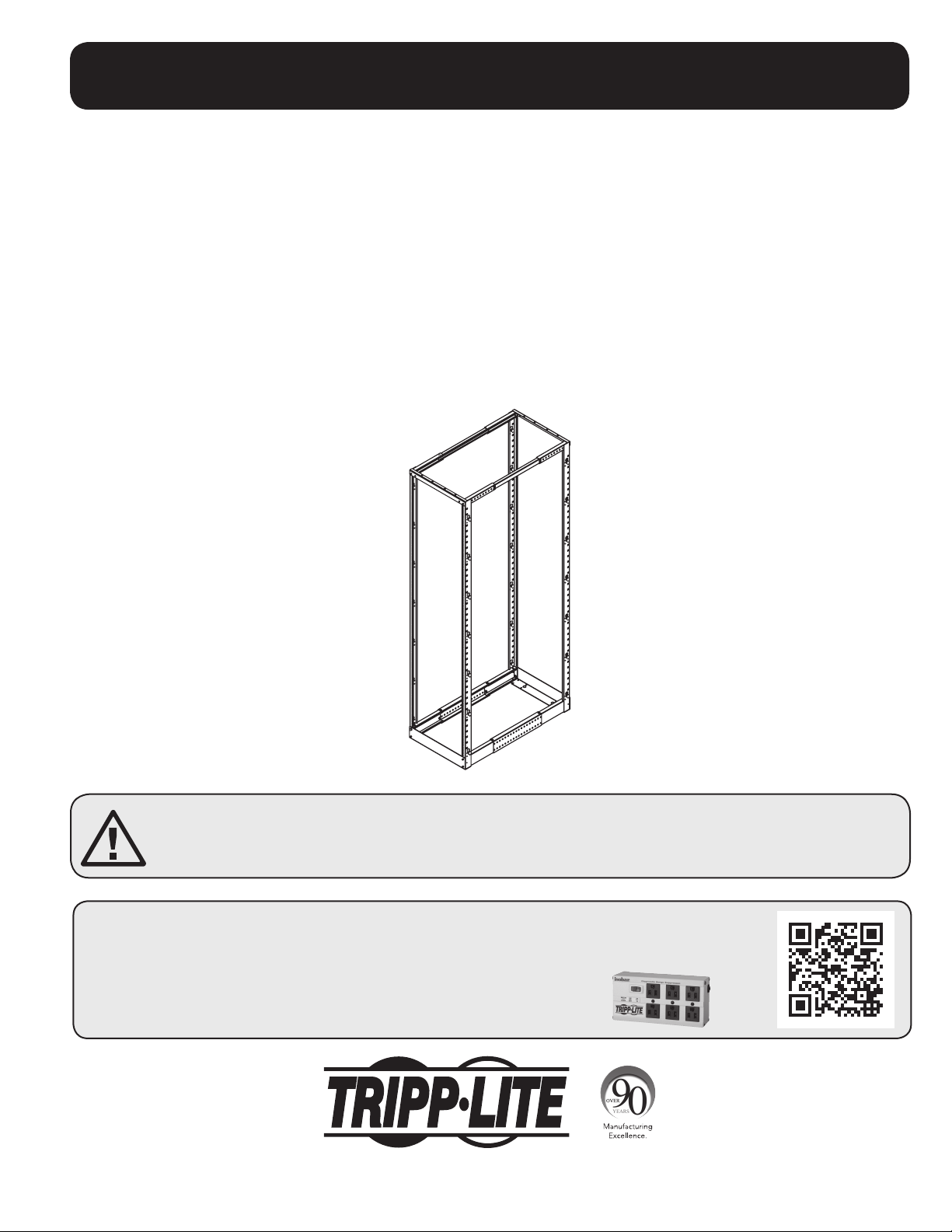
Quick Assembly Guide
SmartRack™ 4-Post Open Frame Racks
(SR4POST, SR4POST1224,
SR4POST13, SR4POST25)
Contents:
Section 1 – Parts Identification
Section 2 – Rack Assembly
Section 3 – Optional Casters
Section 4 – Service & Warranty
SAVE THESE INSTRUCTIONS
This manual contains important instructions and warnings that must be followed during installation.
Failure to comply may affect the warranty.
PROTECT YOUR INVESTMENT!
Register your product for quicker service and ultimate peace of mind.
You could also win an ISOBAR6ULTRA surge protector—a $100 value!
www.tripplite.com/warranty
1111 W. 35th Street, Chicago, IL 60609 USA • www.tripplite.com/support
Copyright © 2015 Tripp Lite. All rights reserved. All trademarks are the sole property of their respective owners.
1
Page 2
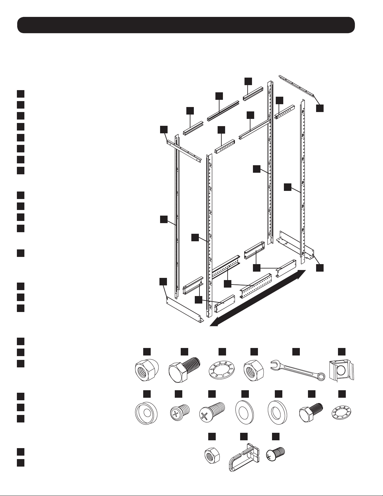
1 – Parts Identification
After opening the shipping box, lay out the parts on a flat surface for identification. If anything is missing or
damaged, go to www.tripplite.com/support for assistance.
Note: SR4POST is shown. SR4POST13 & SR4POST25 are shorter (13U & 25U, respectively) and SR4POST1224 uses round/threaded
equipment mounting holes instead of square holes. However, the rack assembly process for all 4 models is identical.
Rack Components
A
“Left” Vertical Rail (2)
B
“Right” Vertical Rail (2)
C
Base Bracket (2)
D
Bottom Corner Section (4)
E
Bottom Center Section (2)
F
Top Corner Section (4)
G
Top Center Section (2)
H
Top Bracket (2)
Rack Assembly Hardware
I
M8 Acorn/Cap Nuts (12)
J
M8 Bolts (16)
K
M8 Washers (28)
L
M8 Hex Nuts (4)
Rack Assembly Tool
M
M8 (13 mm) Wrench
F
G
F
H
F
G
F
H
B
A
A
B
Equipment Mounting Hardware
(SR4POST, SR4POST13, SR4POST25 Only)
N
M6 Cage Nuts (Qty. varies per model)
O
PVC Cup Washers (Qty. varies)
P
M6 Phillips-Head Screws (Qty. varies)
Equipment Mounting Hardware
(SR4POST1224 Only)
Q
#12-24 Phillips-head Screws (50)
R
Black PVC Washers (50)
S
White PVC Washers (50)
Grounding Hardware
(Optional Installation)
T
M4 Hex Nuts (2)
U
M4 Bolts (2)
V
M4 Washers (2)
Cable Management Hardware
(Optional Installation)
W
Cable Management Hooks (Qty. varies)
X
Hook Mounting Screws (Qty. varies)
D
C
E
C
D
ADJUSTABLE MOUNTING DEPTH: 22 TO 36 in.
I
O
J
K
L
P Q R S
V
W X
M
N
T
U
2
Page 3
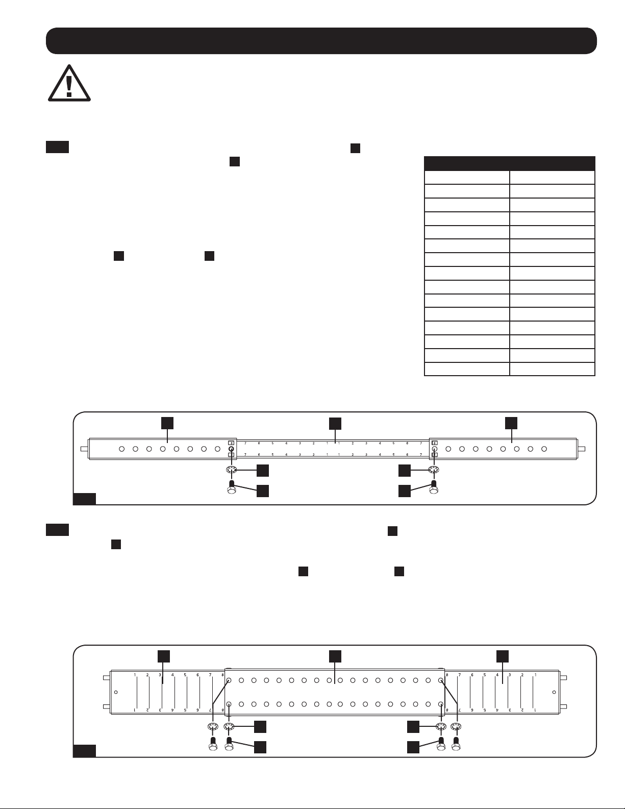
2 – Rack Assembly
Warning: Install the rack in a controlled, structurally sound, indoor environment with
a level floor. Use appropriate caution when moving the rack and consider whether you
require assistance. Assemble the rack completely and confirm its stability before
attempting to install equipment in the rack.
Note: SR4POST is shown, but the assembly process is identical for SR4POST1224, SR4POST13, & SR4POST25.
2-1
Assemble a top section by sliding two top corner sections
F
over
the ends of a top center section G. Align the sections so the index
numbers printed on the center section show through the cutouts
in the corner sections. The index numbers correspond to the rack’s
mounting depth, which is adjustable from 22 inches to 36 inches in
1-inch increments. You can set the rack to the required mounting
depth by cross-referencing the index numbers with the table at
right. When the sections are aligned at the required depth, use an
M8 bolt
J
and M8 washer
K
to fasten each section in place. The
bolt will pass through the corner section and into threaded holes in
the center section. Tighten the bolts approximately 90% with the
included wrench – they should be fixed in place, but not completely
tightened.
Note: You’ll finish tightening all nuts and bolts when the rack is fully assembled.
Repeat the process in Step 2-1 to assemble the other top section.
Make sure the depths match by using the same pair of index
numbers. Lay the assembled sections side by side to confirm that
they’re the same length.
F F
G
Rack Depth Index
Mounting Depth Index Numbers
36 in. 8 and 8
35 in. 7 and 8
34 in. 7 and 7
33 in. 6 and 7
32 in. 6 and 6
31 in. 5 and 6
30 in. 5 and 5
29 in. 4 and 5
28 in. 4 and 4
27 in. 3 and 4
26 in. 3 and 3
25 in. 2 and 3
24 in. 2 and 2
23 in. 1 and 2
22 in. 1 and 1
K K
J J
2-1
2-2
Assemble a bottom section by sliding two bottom corner sections
D
inside the ends of a bottom center
section E. The index numbers printed on the corner sections correspond to the rack’s mounting depth. Align
the sections so the index numbers match the numbers you used for the top sections. When the sections are
aligned at the correct depth, use two M8 bolts
J
and M8 washers
K
to fasten each section in place. The
bolts will pass through the center section and into threaded holes in the corner sections. Tighten the bolts
approximately 90% with the included wrench.
Repeat the process in Step 2-2 to assemble the other bottom section. Lay the assembled top and bottom
sections side by side to confirm that all sections are the same length.
D E D
K K
2-2
J J
3
Page 4

2 – Rack Assembly continued
2-3
Lay out a left vertical rail A, right vertical rail B,
assembled top section
bottom section
D/E/D
floor or a stable work surface. Place all the
pieces facedown. The assembled top and
bottom sections are facedown when the inserted
bolt heads are facedown. The vertical rails are
facedown when the rails are laying flat on the
side that has keyhole mounting slots. Insert the
threaded M8 studs at the ends of the top and
bottom sections through the corresponding holes
in the vertical rails, but do not fasten yet.
2-4
Fasten a base bracket C to the threaded M8
studs at the end of the assembled bottom section
with two M8 acorn/cap nuts I and M8 washers
K
. Tighten 90%. (The threaded M8 studs should
pass through the vertical rail first, then the base
bracket.)
F/G/F
and assembled
in a rectangle on the
2-3
F
G
F
A
B
D
E
D
C
2-5
Fasten a top bracket
H
to the threaded M8 stud
at the end of the assembled top section with an
M8 acorn/cap nut
I
and M8 washer
K
90%. (The threaded M8 stud should pass through
the vertical rail first, then the top bracket.)
. Tighten
2-4
2-5
H
K
K
C
I
H
I
4
Page 5

2 – Rack Assembly continued
2-6
Fasten a left vertical rail
A
and assembled
bottom section D/E/D to the base bracket
I
with two M8 acorn/cap nuts
K
. Tighten 90%. (The threaded M8 studs at the
and M8 washers
end of the assembled bottom section should
pass through the vertical rail first, then the base
bracket.)
2-7
Fasten an assembled top section
the top bracket
an M8 acorn/cap nut
C
and left vertical rail
I
and M8 washer K.
Tighten 90%. (The threaded M8 stud at the
end of the assembled top section should
pass through the vertical rail first, then the
top bracket.)
F/G/F
A
C
to
with
A
D
K
I
C
D
E
A
D
2-6
C
F
G
F
F
A
K
I
2-8
Fasten a base bracket C and right vertical rail
B
to the threaded M8 studs at the end of the
assembled bottom section
D/E/D
with two
M8 acorn/cap nuts I and M8 washers K. Also
fasten the base bracket to the threaded M8 studs
at the end of the other assembled bottom section
with two M8 acorn/cap nuts I and M8 washers
K
.Tighten 90%. (The threaded M8 studs should
pass through the vertical rails first, then the base
bracket.)
2-7
2-8
A
C
C
D
B
B
K
I
C
C
C
D
D
E
D
K
I
5
Page 6

2 – Rack Assembly continued
2-9
Fasten a top bracket
H
to the threaded M8
stud at the end of the assembled top section
F/G/F
with an M8 acorn/cap nut I and M8
washer K. Also fasten the base bracket to
the threaded M8 stud at the end of the other
assembled bottom section with an M8 acorn/
cap nut I and M8 washer K.Tighten 90%.
(The threaded M8 studs should pass through
the vertical rails first, then the top bracket.)
2-10
Place the rack upright on a level surface and
confirm that the rack is stable. Tighten all nuts
and bolts until fully secure. (If you are installing
optional casters, follow the instructions in
Section 3, then return to this step.)
2-9
F
F
G
H
H
F
K
I
K
H
F
I
Mount your equipment in the rack by following
the mounting instructions in the manufacturer’s
documentation.
Note: If you require additional stability, order Tripp Lite’s
Bolt-Down Kit (model SRBOLTDOWN, sold separately) to
fasten the rack to the floor. SRBOLTDOWN is not compatible
with casters.
2-11
(Optional Ground Connection) Use the included
M4 nuts T, bolts U and washers V to fasten a
user-supplied ground wire to the rack and to your
facility’s ground connection. There is a ground
connection hole at each lower corner of the rack.
2-10
100%
T
V
U
6
2-11
T
V
U
Page 7

2 – Rack Assembly continued
2-12
(Optional Cable Management Hooks) Fasten
the included cable management hooks W to the
vertical rack rails with the included screws X.
W
X
2-12
3 – Optional Casters
Warning: Do not attempt to install casters while equipment is installed in the rack.
Note: Caster installation requires Tripp Lite’s Heavy-Duty Rolling Caster Kit (model SRCASTER, sold separately). The kit includes four casters
and the M6 hardware required to mount the casters to the bottom of the rack.
3-1
Place the empty rack on its side.
3-2
Place a caster AA at one of the bottom outside
corners of the rack and line up the holes in the
caster with the holes in the rack.
3-3
Place an M6 washer BB over an M6 bolt CC and
insert the bolt through one of the caster mounting
holes in the bottom inside corner of the rack and
then through the corresponding mounting hole in
the base of the caster.
3-4
Place an M6 washer BB and an M6 nut DD over
the end of the M6 bolt CC, then tighten 90%.
3-5
Repeat Step 3-3 and Step 3-4 until all four
bolts are in place, then tighten all the nuts and
bolts until the caster is secure.
3-6
Repeat Steps 3-2 through 3-5 until all four
casters are mounted securely.
3-7
Insert an M8 bolt J into the hole in each bottom
corner, fasten with an M8 washer K and M8 hex
nut L and tighten securely. (The M8 hardware is
included with the rack.)
DD
3-1
BB CC
BB
AA
3-6
L
K
3-8
Place the rack upright on a level surface and
confirm that the rack is stable. If you haven’t
already completed Step 2-10, complete it now.
J
3-7
7
Page 8

4 – Service, Warranty & Product Registration
Service
Your Tripp Lite product is covered by the warranty described in this manual. A variety of Extended Warranty and OnSite Service Programs are also available from Tripp Lite. For more information on service, visit www.tripplite.com/
support. Before returning your product for service, follow these steps:
1. Review the installation and operation procedures in this manual to insure that the service problem does not
originate from a misreading of the instructions.
2. If the problem continues, do not contact or return the product to the dealer. Instead, visit www.tripplite.com/
support.
3. If the problem requires service, visit www.tripplite.com/support and click the Product Returns link. From here you
can request a Returned Material Authorization (RMA) number, which is required for service. This simple on-line
form will ask for your unit’s model and serial numbers, along with other general purchaser information. The
RMA number, along with shipping instructions will be emailed to you. Any damages (direct, indirect, special or
consequential) to the product incurred during shipment to Tripp Lite or an authorized Tripp Lite service center is
not covered under warranty. Products shipped to Tripp Lite or an authorized Tripp Lite service center must have
transportation charges prepaid. Mark the RMA number on the outside of the package. If the product is within its
warranty period, enclose a copy of your sales receipt. Return the product for service using an insured carrier to
the address given to you when you request the RMA.
5-Year Limited Warranty
Seller warrants this product, if used in accordance with all applicable instructions, to be free from original defects in material and
workmanship for a period of 5 years from the date of initial purchase. If the product should prove defective in material or workmanship within
that period, Seller will repair or replace the product, in its sole discretion.
THIS WARRANTY DOES NOT APPLY TO NORMAL WEAR OR TO DAMAGE RESULTING FROM ACCIDENT, MISUSE, ABUSE OR NEGLECT. SELLER
MAKES NO EXPRESS WARRANTIES OTHER THAN THE WARRANTY EXPRESSLY SET FORTH HEREIN. EXCEPT TO THE EXTENT PROHIBITED BY
APPLICABLE LAW, ALL IMPLIED WARRANTIES, INCLUDING ALL WARRANTIES OF MERCHANTABILITY OR FITNESS, ARE LIMITED IN DURATION
TO THE WARRANTY PERIOD SET FORTH ABOVE; AND THIS WARRANTY EXPRESSLY EXCLUDES ALL INCIDENTAL AND CONSEQUENTIAL
DAMAGES. (Some states do not allow limitations on how long an implied warranty lasts, and some states do not allow the exclusion or
limitation of incidental or consequential damages, so the above limitations or exclusions may not apply to you. This warranty gives you
specific legal rights, and you may have other rights which vary from jurisdiction to jurisdiction).
WARNING: The individual user should take care to determine prior to use whether this device is suitable, adequate or safe for the use
intended. Since individual applications are subject to great variation, the manufacturer makes no representation or warranty as to the
suitability or fitness of these devices for any specific application.
Use of this equipment in life support applications where failure of this equipment can reasonably be expected to cause the failure of the life
support equipment or to significantly affect its safety or effectiveness is not recommended. Do not use this equipment in the presence of a
flammable anesthetic mixture with air, oxygen or nitrous oxide.
Product Registration
Visit www.tripplite.com/warranty today to register your new Tripp Lite product. You’ll be automatically entered into a drawing for a chance to
win a FREE Tripp Lite product!*
* No purchase necessary. Void where prohibited. Some restrictions apply. See www.tripplite.com for details.
Regulatory Compliance Identification Numbers
For the purpose of regulatory compliance certifications and identification, your Tripp Lite product has been assigned a unique series
number. The series number can be found on the product nameplate label, along with all required approval markings and information. When
requesting compliance information for this product, always refer to the series number. The series number should not be confused with the
marketing name or model number of the product.
Tripp Lite has a policy of continuous improvement. Specifications are subject to change without notice.
1111 W. 35th Street, Chicago, IL 60609 USA • www.tripplite.com/support
8
15-08-019 • 93-3046_revC
 Loading...