

Page 1

1111 W. 35th Street
Chicago, IL 60609 USA
Customer Support: (773) 869-1234
www.tripplite.com
Rackmount
Rackmount Intelligent Network
Safety: p. 2
Owner's Manual
®
SmartPro
UPS Systems (120V)
ESPAÑOL: p. 8
FRANÇAIS: p. 15
Installation: p. 3 - 4
Basic Operation: p. 4 - 7
Storage & Service: p. 7
Specifications: p. 7
Warranty & Insurance: p. 6
Copyright © 1999 Tripp Lite. All rights reserved. SmartPro® is a registered trademark of Tripp Lite.
1
Page 2

Safety
This manual contains important instructions and warnings that should be followed
during the installation, operation and storage of all Tripp Lite UPS Systems.
UPS Location Warnings
• Install your UPS indoors, away from excess moisture or heat, dust or direct
sunlight.
• For best performance, keep the indoor temperature between 32° F and 104° F
(between 0° C and 40° C).
• Leave adequate space around all sides of the UPS for proper ventilation.
UPS Connection Warnings
• Connect your UPS to a three-wire, grounded AC power outlet. Do not remove or
modify the ground pin of the UPS's plug.
• Do not use two-prong adapters with the UPS's plug. Do not plug your UPS into
itself; this will damage the UPS and void your warranty.
• If you are connecting your UPS to a motor-powered AC generator, the generator
must provide clean, filtered computer-grade output.
Equipment Connection Warnings
• Do not use Tripp Lite UPS Systems for life support applications in which a
malfunction or failure of a Tripp Lite UPS System could cause failure or significantly alter the performance of a life-support device.
Battery Warnings
• Your UPS does not require routine maintenance. Do not open your UPS for any
reason. There are no user-serviceable parts inside.
• Battery replacement must be performed by qualified service personnel. Because
the batteries present a risk of electrical shock and burn from high short-circuit
current, observe proper precautions. Unplug and turn off the UPS before
performing battery replacement. Use tools with insulated handles and replace
the existing batteries with the same number and type of new batteries (Sealed
Lead-Acid). Do not open the batteries. Do not short or bridge the battery
terminals with any object.
• The UPS batteries are recyclable. Refer to local codes for disposal requirements
or call 1-800-SAV-LEAD (1-800-728-5323) for complete recycling information.
Do not dispose of the batteries in a fire.
• Do not attempt to add external batteries unless your UPS is equipped with
External Battery Connectors. Connect only Tripp Lite battery packs with the
correct voltage (see voltage requirements label on the rear of your UPS) and the
correct connector color to match your UPS’s External Battery Connector.
• Observe proper polarity when connecting replacement batteries. Only connect
Negative (black) wires to Negative (black) terminals. Only connect Positive (red)
wires to Positive (red) terminals.
• During “hot-swap” battery replacement (when the UPS and connected equipment are turned ON) your UPS will not be able to provide battery backup in the
event of a blackout because the batteries will be momentarily disconnected as
they are exchanged.
2
Page 3
Installation
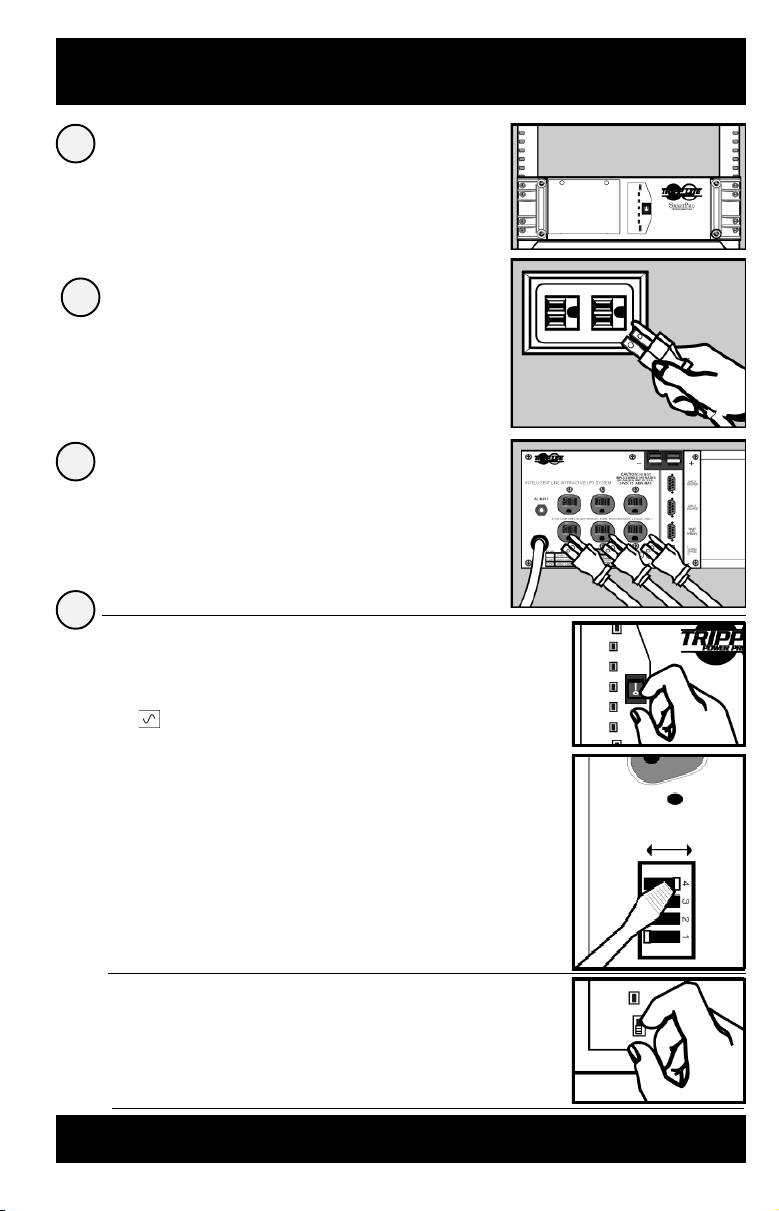
Install rack handles (supplied)
1
and mount UPS in standard
19 in. rack using standard rack
hardware (user supplied).
Install your UPS in the lowest rack position possible.
Plug your UPS into
2
an electrical outlet.
See “Suggested Circuit” in Specifications section
to determine if your model should occupy a 15-amp
or 20- or 30-amp dedicated circuit.
Plug your equipment into
3
your UPS.
Your UPS is designed to support only computer
equipment. Connecting household appliances,
laser printers or surge suppressors is not
recommended.
Turn your UPS ON.
4
Set the System Enable Switch (the
•
location varies by model, see Figures 1
and 2) to the “ENABLE” position.
This switch activates the battery charger and
microprocessor.
The “XXX” light will flash until you engage the
ON/Standby Switch to activate the “ON”
mode.
Figure 1
System Enable Switch
(700 - 1400 VA models)
Front Panel
("I" = ENABLE;
"O" = DISABLE)
Figure 2
System Enable Switch
(2200 - 3000 VA models)
Back Panel
DIP Switch #4
DISABLE ENABLE
Engage the momentary ON/Standby
•
Switch (UPS front panel) and release it
to activate the “ON” mode and supply
power to the UPS receptacles.
(See Figure 3)
Figure 3
ON/Standby Switch
(All models)
Front Panel
DB9 Port Connection (Optional) On Next Page . . .
3
Page 4
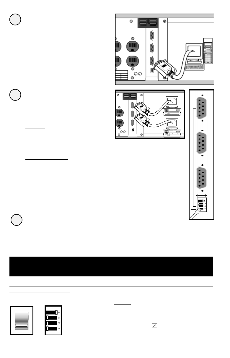
DB9 Port Connection
1
–Optional–*
Using Tripp Lite cable, connect your
primary server’s DB9 port to the single
DB9 port labeled “SMART” (which
provides complete intelligent RS-232
communications).**
If your UPS model has
2
multiple DB9 ports and
you have additional
computers:
All Models
Connect them to the DB9 ports labeled
“BASIC” (which provide basic, contactclosure shutdown capabilities).
See Figure 1.
2200 - 3000 VA Models
Set their corresponding LAN Interface DIP
Switches to the ACTIVATE (LEFT) position.
See Figure 2 for which switch controls
which port.***
Figure 1
Figure 2
LAN INTERFACE DIP
SWITCHES #2 & #1
(2200 - 3000 VA models)
ACTIVATE
DEACTIVATE
Load software and run the installation
3
program appropriate for your operating system.
* Serial port connections are optional. Your UPS will function properly without these connections.
** The “SMART” DB9 port is always enabled and is not controlled by the LAN Interface DIP Switches.
*** If you do not connect a computer to either of the “BASIC” DB9 ports, set their corresponding LAN Interface DIP Switches to the
DEACTIVATE (RIGHT) position. Note: DIP Switch #3 has no function.
Basic Operation
Switches
System Enable Switch*
700 - 1400 VA
models
4
2200 - 3000 VA
models
This switch activates the battery charger and intelligent
microprocessor.
when your UPS is plugged in. Set the switch to “DISABLE”
only if you store or ship your UPS (to reduce battery drain).
*Note: the location of the switch varies by model. The “XXX” light will flash until you engage the
ON/Standby Switch to activate the “ON” mode (power ON at the UPS receptacles).
Always leave it in the “ENABLE” position
Page 5
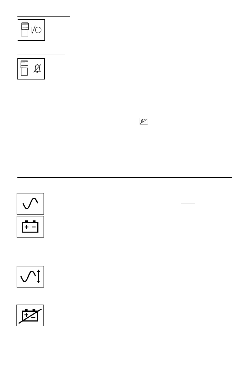
On/Standby Switch
This momentary switch controls power to the UPS receptacles.
Engage it momentarily and release it to toggle between the “ON”
mode (power ON at the UPS receptacles) and “Standby” mode (power
OFF at the UPS receptacles).
Mute/Test Switch
Use this momentary switch to do two things:
Silence the blackout alarm
Engage this switch and release it. Note: when the battery is nearly
depleted, the alarm resumes (and cannot be silenced) to alert you to
immediately shut down connected equipment.
Test your UPS’s battery charge
Leave your connected equipment ON. With your UPS plugged in
and completely turned ON, engage this switch; hold it there for 5
seconds and release it. The UPS will momentarily switch to
battery to test its charge. The “XXX” light will turn ON and the
alarm may sound if your UPS fails a self-test and/or the UPS
battery is less than fully charged. Let the UPS charge for 12 hours
and perform a second self-test. If the light continues to stay on,
contact Tripp Lite for service. CAUTION: Do not unplug your UPS
to test its batteries. This will remove safe electrical grounding and
may introduce a damaging surge into your network connections.
Indicator Lights
All Indicator Light descriptions apply when the UPS is plugged into a wall outlet and
turned ON.
This green light will shine constantly to indicate AC power is available
at the receptacles. It will flash to indicate AC power
“System Enable Switch” and “ON/Standby Switch” descriptions above.)
This multi-colored light displays 7 separate UPS battery charge
conditions. It will turn from red (low) to yellow (medium) to green (full)
to show you the level of battery charge. If the light is constant, then your
UPS is operating from line power and the battery is charging. If the light
is flashing, then your UPS is operating from battery power and the
battery is discharging. When the light flashes red, close any files you
are working on and shut down your computer.
Whenever your UPS is automatically correcting high or low AC line
voltage, this green light will turn ON and the UPS will gently click. The
more the UPS has to correct voltage, the more the green light will turn
ON and the more the UPS will click. These are both normal, automatic
operations of your UPS, and no action is required on your part.
is not available. (See
This red light will turn ON if your UPS fails a self-test and/or the UPS
battery is less than fully charged. Let the UPS charge for 12 hours and
perform a second self-test. If the light continues to stay on, contact
Tripp Lite for service.
5
Page 6
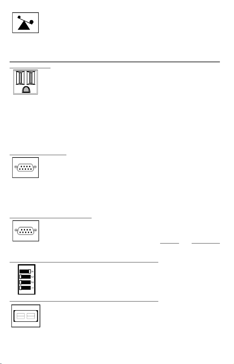
This multi-colored light displays 4 separate UPS load conditions. It will
turn from green (low) to yellow (medium) to red (high) as you connect
equipment to show you the load level your UPS is supporting. When the
light is red your UPS is supporting a load above 85% of its capacity. If
the red light begins flashing, your UPS is severely overloaded. Remove
overload immediately until light stops flashing.
Other UPS Features
AC Receptacles
The receptacles provide your connected equipment with AC line power
during normal operation and battery power during blackouts and
brownouts. They also protect your equipment against damaging surges
and line noise. You can remotely reboot connected equipment by
turning all of the receptacles OFF and ON at once using Tripp Lite UPS
software. Select models, however, feature unique “Remote Reboot
Outlets” (identified on the back panel of your UPS) which allow you to
use Tripp Lite UPS software to remotely reboot equipment connected to
these outlets without interrupting power to equipment connected to the
other outlets.* See software instructions for details.
* Note: constant power is available at the Remote Reboot Outlets (and all other outlets)
unless controlled through Tripp Lite UPS software.
“SMART” RS-232 Port
The RS-232 port connects your UPS to any workstation or server. Use
with Tripp Lite software and #73-0743 cable to monitor and manage
network power and automatically save open files and shut down
equipment during a blackout. This port uses RS-232 communications
to transmit UPS and power conditions (Pin 7 = Transmit; Pin 8 =
Common; Pin 9 = Receive). Contact Tripp Lite Customer Support for
more information and a list of available SNMP, network management
and connectivity products.
“BASIC” Contact-Closure Ports
The contact-closure ports connect your UPS to any workstation or
server. Use with Tripp Lite software and #73-0844 cabling to automatically save open files and shut down equipment during a blackout. This
port sends contact-closure signals to indicate
status. Contact Tripp Lite Customer Support for more information.
LAN Interface DIP Switches (available on select models)
DIP Switches #1 and #2 activate or deactivate remote shutdown through
the “BASIC” Contact-Closure Ports. See “DB9 Port Connection” on page
4 for which switch controls which port. Note: DIP Switch #3 has no
function. DIP Switch #4 serves as the UPS’s “System Enable Switch.”
External Battery Connector (available on select models)
Use this to connect additional Tripp Lite battery packs for additional
runtime. Refer to the label next to the connector for
appropriate Tripp Lite battery pack to connect. Refer to instructions
available with the battery pack for complete connection information and
safety warnings.
6
line-fail and low-battery
Page 7

Battery Replacement Door
Under normal conditions, the original batteries in your UPS will
last several years. Battery replacement should only be performed
by qualified service personnel. Refer to “Battery Warnings” in the
Safety section on page 2. When replacing batteries, qualified
service personnel should follow this procedure: 1) turn UPS OFF;
2) remove the battery door located on the front panel; 3) pull batteries
partially out of the case; 4) make a detailed sketch of the batteries and
the polarity, color and connection of all cables; 5) disconnect battery
terminals; 6) dispose of used batteries; 7) reconnect replacement
batteries exactly as original batteries were; 8) push batteries back into
case and replace cover.*
* You may not receive full runtime until your replacement batteries have fully charged.
Storage & Service
Storage
Turn your UPS OFF: first, engage the ON/Standby Switch and release it to place your
UPS in the “Standby” mode; then set the System Enable Switch* to “DISABLE”; finally,
disconnect the UPS power cord from the wall outlet. If you plan on storing your UPS
for an extended period of time, recharge the UPS batteries once every three months.
Follow steps #1 and #3 in the Installation section and allow the UPS to charge from
4 to 6 hours. If you leave your UPS batteries discharged for an extended period of time,
they will suffer permanent loss of capacity.
* The location of the switch varies by model. See page 3.
Service
If returning your UPS to Tripp Lite, please carefully pack the UPS using the
ORIGINAL PACKING MATERIAL that came with the unit. Enclose a letter describing
the symptoms of the problem. If the UPS is within the 2 year warranty period, enclose
a copy of your sales receipt.
Specifications
Output Capacity (VA/Watts): 700/450 1050/705
Battery Runtime (Half Load/Full Load) Min.: 28/12 23/8
Battery Recharge Time: 2-4 hrs. 2-4 hrs.
Suggested Circuit: 15 amp 15 amp
Approvals: UL, cUL UL, cUL
Output Capacity (VA/Watts): 1400/940 2200/1750
Battery Runtime (Half Load/Full Load) Min.: 26/10 29/13
Battery Recharge Time: 2-4 hrs. 2-4 hrs.
Suggested Circuit: 15 amp 15- or 20- amp dedicated
Approvals: UL, cUL UL, cUL
Output Capacity (VA/Watts): 2200/1750 3000/2400
Battery Runtime (Half Load/Full Load) Min.: 29+/13+ 23+/7+
Battery Recharge Time: 2-4 hrs. 2-4 hrs.
Suggested Circuit: 20-amp dedicated 30-amp dedicated
Approvals: UL, cUL UL, cUL
ALL MODELS:
Input Voltage/Frequency (120V/60 Hz); On Line Input Voltage Range (87 - 140 Volts); Voltage-Regulated Output Voltage Range
(120V +/- 9%); On Battery Output Voltage Range (120V +/- 5%); Output Waveform Line Mode (filtered sinewave); Output Waveform Battery
Mode (PWM sine wave); AC Surge Suppression (exceeds IEEE 587 Cat. A & B standards); AC Noise Attenuation (>40 dB); AC Protection
Modes (H to N, H to G, N to G).
SMART 700 RM SMART 1050 RM
SMART 1400 RM SMART 2200 RM
SMART 2200 RM XL SMART 3000 RM
7
Page 8

Seguridad
Este manual de operación contiene instrucciones y advertencias importantes que deben
seguirse durante la instalación, operación y almacenamiento de los sistemas UPS Tripp Lite.
Advertencias Sobre la Ubicación del Sistema UPS
• Instale este sistema UPS bajo techo, en un lugar sin humedad o calor excesivo y sin
polvo o luz solar directa.
• Para obtener mejores resultados, mantenga la temperatura ambiental entre
32° F y 104° F (entre 0° C y 40° C).
• Permita suficiente espacio alrededor de esta unidad para facilitar la ventilación
apropiada de la misma.
Advertencias Sobre la Conexión del Sistema UPS
• Conecte este sistema UPS a una toma de corriente de CA con conexión a tierra de tres
patas. No remueva o modifique la conexión a tierra del enchufe del sistema UPS.
• No conecte adaptadores de dos patas al enchufe de este sistema UPS. No conecte el
enchufe del sistema UPS a sus propios receptáculos; esto dañará la unidad y anulará su
garantía.
• Si usted desea conectar este sistema UPS a un generador del CA motorizado, asegúrese
que dicho generador proporcione energía de salida limpia y filtrada.
Advertencias Sobre la Conexión de Equipos
• No use sistemas UPS Tripp Lite en aplicaciones de soporte de la vida humana cuando
una falla en la operación del sistema UPS Tripp Lite podría causar fallas o alterar
significativamente el funcionamiento de un dispositivo de soporte de la vida humana.
Advertencias Sobre la Batería
• Este sistema UPS no requiere mantenimiento rutinario. No abra el sistema UPS bajo
ninguna circunstancia. No hay partes que puedan ser reparadas por el usuario dentro de
esta unidad.
• El reemplazo de la batería debe ser realizado por personal técnico capacitado. Deben
obervarse todas las precauciones apropiadas ya que las baterías presentan riesgos de
choques eléctricos y quemaduras por la alta corriente de cortocircuito. Apague y
desenchufe el sistema UPS antes de realizar el reemplazo de la batería. Use herramientas
con asas aisladas y reemplace las baterías del sistema UPS con el mismo número y tipo
de baterías nuevas (Selladas de plomo). No abra las baterías. No corte ni conecte los
teminales de la batería con ningún objeto.
• Las baterías del sistema UPS pueden reciclarse. Consulte en los códigos locales los
requisitos para la disposición de bateríasas. No ponga las baterías en el fuego.
• No intente agregar baterías externas excepto cuando el sistema UPS incluya conectores
para bancos externos de baterías. Conecte solamente bancos de baterías Tripp Lite
y de acuerdo al voltaje correcto (refiérase a la etiqueta de requisitos de voltaje
ubicada en la parte posterior del sistema UPS), y un conector de igual color al
Conector de Baterías Externas del sistema UPS.
• Observe la polaridad apropiada al reemplazar las baterías. Siempre conecte los
alambres Negativos (negros) a los bornes Negativos (negros).
• Durante el intercambio instantáneo de las baterías (“hot-swap”), con el sistema UPS y los
equipos conectados encendidos, el sistema UPS no suministrará energía de batería en
caso de un apagón ya que las baterías estarán momentáneamente desconectadas
mientras se lleva a cabo su intercambio.
8
Page 9

Instalación
Instale las asas para rack
1
(proveídas) e instale el sistema
UPS en un rack estándar de 19
pulgadas usando el material
apropiado (proveído por el
usuario).
Instale el sistema UPS en el estante más bajo del rack.
Enchufe el sistema UPS a una
2
toma de energía eléctrica
Refiérase a la sección “Especificaciones: Circuito Sugerido” para
determinar si este modelo requiere un circuito de 15 amperios ó
circuito dedicado de 20 ó 30 amperios.
Conecte sus equipos al sistema
3
UPS
Este sistema UPS ha sido diseñado para respaldar equipos de
computación solamente. No se recomienda la conexión a este
sistema UPS de dispositivos electrodomésticos, impresoras láser o
supresores de picos.
Encienda el sistema UPS
4
Coloque el Interruptor “System Enable”
•
(Habilitador del Sistema) en la posición
“ENABLE” (Habilitar). (La ubicación del
interruptor “System Enable” variá de
acuerdo al modelo. Vea el Diagrama
1 o 2)
Este interruptor activa el microprocesador y el
cargador de baterías.
La luz “XXX” parpadeará hasta que usted
coloque el interruptor “ON/Standby”
(Encendido/Reserva) en la posición correcta
para activar el modo “ON” (Encendido).
Diagrama 1
Interruptor "System Enable"
(Los modelos 700 - 1400 VA)
Panel Fronte
["I" = ENABLE (Habilitar);
"O" = DISABLE (Inhabilitar)]
Diagrama 2
Interruptor "System Enable"
(Los modelos 2200 - 3000 VA)
Panel Posterior
Interruptor "LAN Interface
Jumper" #4
DISABLE ENABLE
(Inhabilitar) (Habilitar)
Engrane el interruptor momentáneo
•
“ON/Standby” (Encendido/Reserva) en
el panel frontal del sistema UPS, y
suéltelo para activar el modo “ON”
(Encendido) y suministrar energía a los
receptáculos del sistema UPS.
(Vea el Diagrama 3)
Diagrama 3
Interruptor "ON/Standby"
(Todos los modelos)
Panel Fronte
Instrucciones Para la Conexión Opcional del Puerto DB9 en la Próxima Página...
9
Page 10

Conexión del Puerto DB9
1
—Opcional—*
Usando el cable suministrado por
Tripp Lite, conecte el puerto DB9 de
su servidor principal de archivos al
puerto DB9 rotulado “SMART”
(Inteligente), el cual provee
comunicaciones completas e
inteligentes tipo RS-232.**
Si su sistema UPS incluye
2
puertos DB9 múltiples y
usted desea conectar
computadoras
adicionales:
Todos los modelos
Conéctelas a los puertos DB9 rotulados
“BASIC” (Básicos) los cuales incluyen
capacidad básica de cierre.
Vea el Diagrama 1.
Diagrama 1
Los modelos 2200 - 3000 VA
Coloque los interruptores “LAN Interface
Jumper” (Conexiones de Interfases para
Redes) correspondientes a los puertos
básicos o secundarios en la posición
“ACTIVATE” (ACTIVAR). Refiérase al
Diagrama 2 para determinar los puertos
que controla cada interruptor.***
Instale el software ejecutando el programa de
3
instalación apropiado para su sistema operativo.
* La conexión a los puertos seriales es opcional. Este sistema UPS funcionará adecuadamente aún sin estas conexiones.
** El puerto DB9 “SMART” (Inteligente) está siempre activado y no es controlado por los interruptores “LAN Interface Jumper”
(Conexiones de Interfases para Redes).
*** Si usted no desea conectar computadoras a todos los puertos DB9 “BASIC” (Básicos), coloque los interruptores “LAN Interface Jumper”
(Conexiones de Interfases para Redes) correspondientes a los puertos secundarios en la posición “DEACTIVATE” (DESACTIVAR). Nota:
“Jumper #3” (Conexión No. 3) no cumple función alguna.
Diagrama 2
Interruptores
"LAN INTERFACE
JUMPER" #2 & #1
(Los Modelos 2200 3000 VA)
(ACTIVAR)
ACTIVATE
(DESACTIVAR)
DEACTIVATE
10
Page 11

Operación Básica
Interruptores
Interruptor “System Enable” (Habilitador del Sistema)*
Los modelos
700-1400 VA
Interruptor “ON / Standby” (Encendido/Reserva)
Interruptor “Mute/Test” (Silenciador/Autoprueba)
Los modelos
2200-3000 VA
Este interruptor activa el cargador de baterías y el microprocesador
inteligente. Siempre debe estar en la posición “ENABLE”
(Habilitar) mientras el sistema UPS esté conectado a la línea de
CA. Coloque el interruptor “System Enable” (Habilitador del
Sistema) en la posición “DISABLE” (Inhabilitar) solamente si
usted desea almacenar o transportar el sistema UPS (esto reduce
el desgaste de las baterías).
*Nota: La ubicación del interruptor “System Enable” variá de acuerdo al modelo. La luz “XXX” parpadeará
hasta que usted coloque el interruptor “ON/Standby” (Encendido/Reserva) en la posición correcta para
activar el modo “ON” (Encendido) y suministrar energía a los receptáculos del sistema UPS.
Este interruptor momentáneo controla la energía al nivel de los
receptáculos del sistema UPS. Engránelo momentáneamente y
suéltelo para pasar alternativamente del modo “ON” (Encendido) y
suministrar energía a los receptáculos del sistema UPS, al modo
“Standby” (Reserva) y desactivar los receptáculos del sistema UPS.
Utilice este interruptor momentáneo para realizar dos funciones:
Silenciar la alarma de apagones
Engrane este interruptor y suéltelo. Nota: esta alarma sonará, y no
podrá ser silenciada, para advertirle que la(s) batería(s) está(n) casi
agotada(s) y que los equipos conectados deben ser apagados
inmediatamente.
Verificar la carga de las baterías del sistema UPS
Mantenga encendidos los equipos conectados. Con el sistema UPS
encendido (ON) y conectado a una línea viva de CA, engrane este
interruptor; sosténgalo por 5 segundos y suéltelo. El sistema UPS
cambiará momentáneamente a batería para verificar su carga. La luz
“XXX” se iluminará y la alarma sonará si el sistema UPS no pasa la
prueba y/o las baterías no están totalmente cargadas. Permita que el
sistema UPS cargue las baterías por 12 horas y repita la autoprueba.
Si la luz continua encendida, comuníquese con Tripp Lite para obtener
información sobre el centro de servicio más cercano a usted.
PRECAUCION: No desconecte el sistema UPS para verificar la
carga de las baterías. Esto eliminará la conexión a tierra y podría
introducir sobretensiones transitorias perjudiciales a las
conexiones de su red.
Luces Indicadoras
Todas las descripciones de la Luces Indicadoras son efectivas mientras el Sistema UPS
está conectado a una línea viva de CA y haya sido encendido (ON).
Esta luz verde se iluminará constantemente para indicar que la energía
de CA está presente en los receptáculos, o parpadeará para indicar que
la energía de CA no está disponible. [Refiérase a las descripciones del
Interruptor “System Enable” (Habilitador del Sistema) e Interruptor
“On/Standby” (Encendido/Pausa) más arriba].
Esta luz multicolor despliega 7 condiciones diferentes acerca de la
carga de la batería del sistema UPS. Se iluminará en rojo (baja), amarillo
(mediana) o verde (completa) para indicar el nivel de carga de la batería.
11
Page 12

Si esta luz está constantemente iluminada, significa que su sistema
UPS está operando con energía de CA y cargando la batería. Si esta luz
parpadea, significa que su sistema UPS está operando con energía de
batería y ésta se está desgastando. Cuando esta luz esté roja y
parpadeando, cierre todos sus archivos activos y apague su sistema de
computación.
Cuando el sistema UPS esté regulando automáticamente el voltaje bajo
o alto de entrada, esta luz verde se iluminará y el sistema UPS emitirá
un leve sonido. Cuanto más irregular sea el voltaje de entrada, más se
iluminará esta luz verde y más sonidos emitirár el sistema UPS. Estas
son condiciones normales y automáticas del sistema UPS y no
requieren ninguna acción de su parte.
Esta luz roja se iluminará si el sistema UPS no pasa la autoprueba y su
batería no está totalmente cargada. Permita que el sistema UPS cargue su
batería por 12 horas y realice una segunda autoprueba. Si la luz continúa
iluminada, comuníquese con Tripp Lite para recibir información acerca del
centro de servicio más cercano a usted.
Esta luz multicolor despliega 4 condiciones diferentes acerca de la carga
conectada al sistema UPS. Se iluminará en verde (baja), amarillo (mediana)
o rojo (alta) a medida que usted conecta sus equipos para indicarle el nivel
de carga respaldado por su sistema UPS. Cuando la luz esté roja, indicará
que el sistema UPS está respaldando una carga superior al 85% de su
capacidad. Si la luz roja parpadea, significa que el sistema UPS ha sido
severamente sobrecargado. Desconecte la sobrecarga inmediatamente hasta
que la luz deje de parpadear.
Otras Características del Sistema UPS
Receptáculos de CA
Los receptáculos suministran a sus equipos conectados energía de CA
durante condiciones normales de operación y energía de batería durante
apagones y caídas de voltaje. También protegen sus equipos contras daños
causados por picos o ruidos de línea. Usted puede reiniciar los equipos
conectados por control remoto apagando todos los receptáculos y
encendiéndolos al mismo tiempo por medio del software para sistemas UPS
de Tripp Lite. No obstante, algunos modelos incluyen receptáculos especiales
rotulados “Remote Reboot” (Reinicio por Control Remoto, identificados en
el panel posterior del sistema UPS) para permitir el uso del software Tripp
Lite para sistemas UPS y reiniciar, por control remoto, los equipos conectados
a estos receptáculos sin interrumpir la energía que alimenta los equipos
conectados al resto de los receptáculos.* Refiérase a las instrucciones que
acompañan dicho software para obtener más información.
* Advertencia: La energía será suministrada constantemente a los receptáculos rotulados “Remote Reboot” (Reinicio
por Control Remoto) y al resto de los receptáculos salvo en ocasiones cuando usted controle estos receptáculos por
medio del software Tripp Lite para sistemas UPS.
Puerto RS-232 “SMART” (Inteligente)
El puerto inteligente RS-232 conecta su sistema UPS a cualquier estación
de trabajo o servidor de archivos. Utilícelo conjuntamente con el software
y cable No. 73-0743 de Tripp Lite para monitorear y administrar la energía
de su red, salvar automáticamente sus archivos activos y cerrar su sistema
durante un apagón. Este puerto utiliza comunicaciones inteligentes tipo
RS-232 para la transmisión de las condiciones de la energía y del sistema
UPS (Pin 7 = Transmitir; Pin 8 = Común; Pin 9 = Recibir). Comuníquese con
el Departamento de Apoyo a Clientes de Tripp Lite para recibir más
información y obtener una lista de productos disponibles para
administración de redes, conectividad y SNMP.
12
Page 13

Puertos “BASIC” (Básicos)
Estos puertos básicos conectan el sistema UPS a cualquier estación de
trabajo o servidor de archivos. Utilícelos conjuntamente con el software
y cable No. 73-0844 de Tripp Lite para salvar automáticamente sus
archivos activos y cerrar el sistema durante un apagón. Estos puertos
envían señales para indicar
fallas en la línea de CA y baja carga de la
batería. Comuníquese con el Departamento de Apoyo a Clientes de
Tripp Lite para obtener más información.
Interruptores “LAN Interface Jumper” (Conexiones de Interfaces de Redes)
Los interruptores “Jumper Switches #1 y #2” (Conexiones No. 1 y No.
2) activan o desactivan la capacidad de cierre por control remoto a
través de los Puertos “BASIC” (Básicos). Refiérase a la sección
“Conexión del Puerto DB9” en la página 10 para obtener información
acerca de los interruptores que controlan los diferentes puertos.
Advertencia: “Jumper #3” (Conexión No. 3) no cumple función alguna.
“Jumper #4” (Conexión No. 4) sirve la función del interruptor “System
Enable” (Habilitador del Sistema) del sistema UPS.
Conector para Baterías Externas (disponible en modelos selectos)
Utilice este conector para agregar bancos externos de baterías de Tripp
Lite y extender el tiempo de respaldo. Refiérase a la etiqueta próxima
al conector para obtener información acerca del tipo de baterías Tripp
Lite que usted puede conectar. Refiérase a las instrucciones que
acompañan los bancos de baterías para obtener información detallada
y advertencias de seguridad.
Puerta para el Reemplazo de la Batería
Bajo condiciones normales, las baterías originales incluidas con este
sistema UPS tendrán una vida útil de varios años de duración. El
reemplazo de las baterías solamente debe ser realizado por personal
técnico capacitado. Refiérase a la sección “Seguridad; Advertencias
sobre la Batería” en la página 8. Al reemplazar las baterías, el personal
técnico capacitado debe seguir este procedimiento: 1) apague el sistema
UPS; 2) remueva la puerta de la batería ubicada en el panel frontal; 3)
jale la batería y déjela parcialmente afuera de la caja; 4) diagrame
detalladamente la batería, polaridad y el color y tipo de conexión de
todos los cables y/o alambres; 5) desconecte los bornes de la batería;
6) desheche las baterías usadas; 7) conecte las nuevas baterías
exactamente como estaban conectadas las anteriores; 8) empuje la
batería hacia adentro de la caja y reemplace la puerta de la misma.*
* Es posible que el sistema UPS no suministre el tiempo total de respaldo mientras las nuevas baterías no hayan sido
totalmente cargadas.
13
Page 14

Almacenamiento y Servicio
Almacenaje
Apague (OFF) el sistema UPS: primero, engrane el interruptor “ON/Standby”
(Encendido/Reserva) y suéltelo para pasar al modo “Standby” (Reserva); Después
coloque el interruptor “System Enable” (Habilitador del Sistema)* en la posición
“DISABLE” (Desactivar); finalmente, desconecte el cable principal del sistema UPS de
la línea de CA. Si usted desea almacenar el sistema UPS por un período prolongado
de tiempo, recargue las baterías del sistema UPS de 4 a 6 horas. Las baterías perderán
permanentemente su capacidad de carga si permanecen desgastadas por un período
extendido de tiempo.
* La ubicación del interruptor “System Enable” variá de acuerdo al modelo (pagina 9).
Servicio
Si usted necesita enviar el sistema UPS al centro de servicio de Tripp Lite, empáquelo
cuidadosamente usando el MATERIAL ORIGINAL DE EMPAQUE incluido con la
unidad. Adjunte una carta describiendo los síntomas del problema. Si la unidad está
dentro del periodo de garantía de 2 años adjunte una copia de su factura original.
Específicaciones Técnicas
SMART 700 RM SMART 1050 RM
Capacidad de Salida (VA/Watts): 700/450 1050/705
Tiempo de Respaldo (Media Carga/
Plena Carga) Minutos: 28/12 23/8
Tiempo de Recarga de la Batería: 2-4 hrs. 2-4 hrs.
Circuito Sugerido: 15 amperios 15 amperios
Certificaciones: UL, cUL UL, cUL
SMART 1400 RM SMART 2200 RM
Capacidad de Salida (VA/Watts): 1400/940 2200/1750
Tiempo de Respaldo (Media Carga/
Plena Carga) Minutos: 26/10 29/13
Tiempo de Recarga de la Batería: 2-4 hrs. 2-4 hrs.
Circuito Sugerido: 15 amperios dedicado de 15 ó 20 amperios
Certificaciones: UL, cUL UL, cUL
Capacidad de Salida (VA/Watts): 2200/1750 3000/2400
Tiempo de Respaldo (Media Carga/
Plena Carga) Minutos: 29+/13+ 23+/7+
Tiempo de Recarga de la Batería: 2-4 hrs. 2-4 hrs.
Circuito Sugerido: dedicado de 20 amperios dedicado de 30 amperios
Certificaciones: UL, cUL UL, cUL
TODOS LOS MODELOS:
Voltaje / Frecuencia de Entrada (120V/60Hz); Gama de Voltaje de Entrada en Línea (87 - 140V); Gama de Voltaje Regulado de Salida
(120V +/- 9%); Gama de Voltaje de Salida en Batería (120V +/- 5%); Tipo de Onda de Salida en Línea (senoidal filtrada); Tipo de Onda de Salida
en Batería (senoidal modulada en ancho de pulso); Supresión de Picos de CA (excede las normas de IEEE 587 Categorías A y B); Atenuación
de Ruidos de CA (>40 dB); Modos de Protección de CA (Positivo a Neutro, Positivo a Tierra, Neutro a Tierra).
SMART 2200 RM XL SMART 3000 RM
14
Page 15

Sûreté
Ce manuel contient des instructions et des avertissements importantes pour l’installation,
l’opération et l’emmagasinage de tout système d’onduleur Tripp Lite.
Avertissements du Placement du Système d’Onduleur
• Installez le système d’onduleur à l'intérieur, loin d’humidité, de chaleur, de
poussière et de lumière de soleil directe.
• Pour la meilleure performance, maintenez la température à l'intérieur entre
0° C et 40° C (32° F et 104° F).
• Garder plein d’espace autour du système d’onduleur pour maintenir une ventilation
convenable.
Avertissements de la Connexion du Système d’Onduleur
• Branchez votre système d’onduleur à une prise d’alimentation c.a. de trois fils et mise
à terre. N’ôtez pas et ne modifiez pas le fil de terre du prise du système d’onduleur.
• N’utilisez pas les adaptateurs de deux fils pour le prise du système d’onduleur. Ne
branchez pas le système d’onduleur à soi-même; cela endommagera le système
d’onduleur et nullifiera votre garantie.
• Si vous branchez votre système d’onduleur à une gazogène motorizée, celui-ci doit
fournir une propre alimentation de sortie filtrée convenable aux ordinateurs.
Avertissements de la Connexion d’Equipement
• N’utilisez pas les systèmes d’onduleur Tripp Lite avec les applications de support-vie,
où un défaut du système d’onduleur peut causer un défaut de, ou peut modifier la
performance de, l’équipement de support-vie.
Avertissements de la Batterie
• Votre système d’onduleur n’exige pas d’entretien routine. N’ouvrez pas votre système
d’onduleur pour n’importe raison. Il n’y a pas de parties serviceables par l’utilisateur.
• Le remplacement de la batterie doit être fait par un personnage de service qualifié.
Car les batteries présentent un risque de choc éléctrique et de brûlure du courant de
court-circuit, observez les precautions propres. Arrêtez et débranchez le système
d’onduleur avant de remplacer les batteries. Utilisez des outils insulés et remplacez
les batteries avec des batteries du même nombre et du même type (Plomb et Acide
Fermé). N’ouvrez pas les batteries. Ne courtez pas et ne créez pas un pont aux
terminales de la batterie avec aucun objet.
• Les batteries du système d’onduleur sont recycleables. Vous référez aux codes
locaux pour les exigences d’enlèvement ou téléphonez à 1-800-SAV-LEAD
(1-800-728-5323) pour les informations complètes. Ne disposer pas des
batteries en feu.
• N’essayez pas d’ajouter des batteries externes, sauf si votre système d’onduleur
est fournit des connexions pour les paquets de batterie externes. Reliez
seulement les packs de batterie de Tripp Lite à la tension correcte (voir
l’étiquette de conditions de tension sur l’arrière de votre UPS) et à la couleur
correcte de connecteur pour coincider avec votre Connecteur de Batterie
Externe d’UPS.
• Observez la polarité juste en connectant les batteries de remplacement.
Connectez seulement les fils négatives (noirs) aux terminales négatives (noirs).
Connectez seulement les fils positives (rouges) aux terminales positives
(rouges).
• En remplaçant les batteries par “hot-swap” (quand le système d’onduleur et le
matériel branché sont allumés) votre système d’onduleur ne pourra pas fournir
un secours par batterie en cas d’une coupure d’électricité parce que les batteries
seront séparées de l’unité.
15
Page 16

Installation
Installez les poignées de mon-
1
tage (fournies) et montez l’UPS
aux normes standard de 19
pouces à l’aide du matériel de
montage standard (fourni par
l’utilisateur).
Branchez votre UPS à une
2
sortie électrique.
Voir “Circuit Suggéré” dans la section Caractéristiques pour
déterminer si votre modèle occupe un circuit 15 ampères ou
circuit consacré de 20 ou 30 ampères.
Branchez votre matériel dans
3
votre UPS.
Votre UPS peut supporter du matériel informatique seulement.
Vous surchargerez votre UPS si vous connectiez les appareils
domestiques, les imprimantes à laser ou les suppresseurs de
surtensions.
Mettez votre UPS en marche.
4
•
Placez le Commutateur de «System
Enable» («Système Valide») à la
position «ENABLE» (la position de
«Validation»).
(voir Schéma 1 ou 2)
Ce commutateur lance le chargeur de
batterie et le microprocesseur.
Le voyant lumineux «XXX» flashera
jusqu’à ce que vous engagiez le
commutateur ON/Standby pour lancer
le mode «ON».
Schéma 1
Interrupteur "System Enable"
(700 - 1400 VA modeles)
Panneau d'avant
["I" = ENABLE (VALIDATION);
"O" = DISABLE (HORS FUNCTION)]
Schéma 2
Interrupteur "System Enable"
(2200 - 3000 VA modeles)
Panneau d'arrière
Cavalier #4
DISABLE ENABLE
(HORS FUNCTION) (VALIDATION)
•
Engagez le commutateur ON/
Standby momentanément (panneau
avant de l’UPS) et libérez-le pour
lancer le mode «ON» et fournir
l’alimentation électrique aux
réceptacles de l’UPS.
(Voir Schéma 3)
16
Schéma 3
Interrupteur "ON/Standby"
(Toutes les modeles)
Panneau d'avant
Page 17

Connexion du Port DB9
1
–Facultatif*–
Utilisant le cablâge Tripp Lite,
branchez le port DB9 de votre
serveur de base au port unique DB9
«SMART» (qui fournit les communications RS-232 intelligentes
complètes).**
Si votre système
2
d’onduleur a des ports
DB9 multiples et vous
avez des ordinateurs
multiples:
Toutes les modeles
Branchez-les aux ports DB9 «BASIC»
(qui fournit la capacité pour l’arrêt de
base). Voir Schéma 1.
2200 - 3000 VA modeles
Mettez leurs Interrupteurs de
Cavaliers d’interface LAN
correspondants en position ACTIVATE (ACTIVATION). Voir
pour savoir quel commutateur
controle quel port.***
Schéma 2
Schéma 1
Schéma 2
Interrupteurs de Cavaliers
d’interface LAN #2 & #1
(2200 - 3000 VA modeles)
Panneau d'arriere
(ACTIVATION)
ACTIVATE
(DESACTIVATION)
DEACTIVATE
Montez le logiciel et executez le programme
3
d’installation approprié pour votre système.
* Les connexions du port série sont facultatifs. Votre système d’onduleur fonctionnera proprement sans ces connexions.
** Le port DB9 «SMART» est toujours en fonction et n’est pas contrôlé par les Interrupteurs de Cavaliers d’interface LAN.
*** Si vous ne connectiez pas un ordinateur aux ports DB9 «BASIC,» mettez leurs Interrupteurs de Cavaliers d’interface LAN en position
DEACTIVATE (DESACTIVATION). Notez: Cavalier #3 n’a pas de fonction.
17
Page 18

Opération de Base
Commutateurs
Commutateur de «System Enable» («Système Valide»)
(700 - 1400 VA
modeles)
Commutateur «ON/Standby» (Marche/Attente)
Commutateur de «Mute/Test» (Amortissage/Test)
(2200 -3000 VA
modeles)
Ce commutateur lance le chargeur de batterie et le microprocesseur
intelligent. Laissez-le
«Validation») quand votre UPS est branché. Placez le Commutateur de
Système Valide sur «DISABLE» (la position de «Hors Function») seulement
si vous entreposez ou expédiez votre UPS (pour réduire le drain de
batterie).
Note: le voyant lumineux «XXX» flashera jusqu’à ce que vous engagiez le commutateur ON/Standby
pour lancer le mode «ON» (mise sous tension aux réceptacles de l’UPS).
Ce commutateur momentané contrôle la puissance aux réceptacles de
l’UPS. Engagez-le momentanément et libérez-le pour permuter entre le
mode «ON» (mise sous tension aux réceptacles de l’UPS) et le mode
«Standby» (mise hors tension aux réceptacles de l’UPS).
Utilisez ce commutateur momentané pour faire deux choses:
Amortissez l’alarme d’arrêt total.
Engagez ce commutateur et libérez-le. Note: quand la batterie est presque
épuisée, l’alarme reprend (et ne peut pas être amortie) pour vous alerter de
couper immédiatement l’alimentation du matériel relié.
Testez la charge de la batterie de l’UPS.
Laissez votre matériel relié sur ON. Avec votre UPS complètement branché sur
la position ON, engagez ce commutateur; tenez-le là pendant 5 secondes et
libérez-le. L’UPS commutera momentanément sur la batterie pour tester sa
charge. Le voyant lumineux «XXX» s’allumera et l’alarme peut retentir si votre
UPS échoue à l’auto-test et/ou la batterie de l’UPS est moins qu’entièrement
chargée. Laissez l’UPS charger pendant 12 heures et exécutez un deuxième
auto-test. Si le voyant lumineux continue à rester allumé, contactez Tripp Lite
pour le service.
ATTENTION: Ne débranchez pas votre UPS pour tester ses batteries. Ceci
enlèvera la sureté de la prise électrique de terre et peut présenter une
montée subite préjudiciable dans vos connexions de réseau.
toujours sur la position «ENABLE» (la position de
Indicateurs Lumineux
Toutes descriptions sur l’indicateur lumineux s’appliquent lorsque votre UPS est connecté
à la prise murale et sur la position MARCHE («ON»).
Cet indicateur vert brillera constammant pour indiquer que les prises du système
d’onduleur fournit de l’alimentation c.a. Il clignotera pour indiquer que les prises
ne fournit pas de l’alimentation c.a. (Voir les déscriptions des l’interrupteurs
«System Enable» et «On/Standby» au dessus.)
Cet indicateur multi-coloré représente 7 conditions différentes de la charge de
la batterie de l’UPS. Il change de rouge (charge basse) à jaune (mi-charge) à vert
(charge complète) pour indiquer le niveau de la charge de la batterie. Si
l’indicateur est allumé constammant, l’UPS fonctionne de l’alimentation c.a. et
la batterie se charge. Si l’indicateur clignote, l’UPS fonctionne de l’alimentation
par batterie (et la batterie se décharge). Si l’indicateur clignote en rouge, fermez
des fichiers ouverts et arrêtez votre ordinateur.
18
Page 19

Quand votre système d’onduleur correcte la tension haute ou basse, cet
indicateur vert s’allume et le système d’onduleur claquera doucement. Plus
l'UPS corrige la tension, plus l’indicateur vert s’allumera et plus le système
d’onduleur claquera. Ces opérations sont normales et automatique, et il ne faut
rien faire.
Cet indicateur rouge s’allumera si votre système d’onduleur échoue un autotest et la batterie n’a pas une charge complète. Laissez le système d’onduleur
charger pendant 12 heures est refaisez l’auto-test. Si l’indicateur est cependant
allumé, contactez Tripp Lite pour du service.
Cet indicateur multi-coloré indique 4 conditions de la charge du système
d’onduleur. Il change de vert (charge basse) à jaune (mi-charge) à rouge (charge
complète) pendant que vous connectez votre équipement pour vous montrer
la charge que l’UPS supporte. Quand l’indicateur est rouge,
votre UPS supporte une charge plus de 85% de sa capacité. Si l’indicateur rouge
clignote, votre UPS est sévèrement surchargé. Débranchez l’équipement qui
produit la surcharge tout de suite jusque l’indicateur ne clignote plus.
Autres Caractéristiques du Système d’Onduleur
Prises CA
Port Intelligent RS-232
Port de Fermeture de Contact de Base
Interrupteurs de Cavaliers d’interface LAN (disponibles avec certains modèles)
Les prises fournissent votre équipement connecté d’alimentation de ligne c.a.
pendant l’opération normale; elles fournissent votre équipement connecté
d’alimentation par batterie pendant les coupures de courant et les baisses de
tension. Elles protègent votre équipement contre les surtensions et les parasites endommageants. Vous pouvez relancer de loin l’équipement branché par
couper l’alimentation des prises du système d’onduleur et puis la rétablir,
utilisant le logiciel Tripp Lite. Quelques modèles cependant offrent les prises
«Remote Reboot» (relancement à loin) (identifiées à l’arrière du système
d’onduleur) qui vous permettent utiliser le logiciel Tripp Lite pour relancer
l’équipement y branché sans interrompre l’alimentation à l’équipement branché
aux autres prises.
Notez: alimentation constante est disponible aux prises «Remote Reboot» (relancement à loin) et aux autres prises
sauf elle soit contôlée par le logiciel de Tripp Lite. Voir les instructions avec le logiciel pour plus d’informations.
Le port RS-232 connecte votre système d’onduleur à n’importe station de travail
ou serveur. Utilisez-le avec le logiciel et le cablâge Tripp Lite pour contrôler
l’alimentation du réseau, pour sauvegarder automatiquement les fichiers
ouverts et pour arrêter l’équipement en cas d’une coupure de courant. Ce port
utilise les communications RS-232 pour transmettre d’informations sur les
conditions de l’alimentation du système d’onduleur (Broche 7 = transmette;
Broche 8 = Commun; Broche 9 = Reçoit). Contactez l’Assistance Client de Tripp
Lite pour plus d’informations et une liste des produits disponibles de SNMP,
gestion de réseau et connectivité.
Les ports de fermeture de contact branchent votre système d’onduleur à
n’importe station de travail or serveur de fichiers. Utilisez-le avec le logiciel Tripp
Lite et le cablâge #73-0844 pour sauvegarder automatiquement les fichiers
ouverts et arrêter le matériel pendant une panne d’électricité. Ce port envoie
des signals de fermeture de contact pour indiquer
charge basse. Contactez l’Assistance Client de Tripp Lite pour plus d’informations.
Les cavaliers #1 et #2 font active ou déactive l’arrêt à loin par les ports de base
«BASIC.» Voyez la section «Connexion du Port DB9» à la page 17 pour plus
d’informations sur quel interrupteur contrôle quel port. Notez: Cavalier #3 n’a
pas de fonction. Cavalier #4 serve de l’interrupteur «System Enable» du système.
défaut de ligne et batterie à
Connecteur de Batteries Externes (disponible sur certains modèles)
Utilisez ce connecteur pour brancher les paquets de batteries Tripp Lite pour
augmenter le temps secours du système d’onduleur. Vous référez à l’etiquette
à côté du connecteur pour des détailles sur le paquet de batteries convenable.
Vous référez aux instructions disponibles avec le paquet de batteries pour des
informations complètes de connexion et des avertissements de sureté.
19
Page 20

Porte Commode du Remplacement de la Batterie
Remplacement de la Batterie (pour les personnages de service qualifiés):
Avertissement! Le courant haut de court-circuit de la batterie présent un risque
de choc électrique et de brûlure. Observez les précautions et utilisez des outils
insulés. Ne courtez pas et ne créez pas un pont aux terminales de la batterie.
Remplacez la batterie avec une batterie du même type (Plomb et Acide Fermé). La
batterie est recyclable (ne l’ouvrez pas et ne le déstriusez pas en feu). Vous référez aux codes
locaux pour les regulations de déstruction. Le procédé pour remplacement: 1) Arrêtez et
débranchez l’UPS; 2) tirez sur la batterie partialement dehors de l’UPS; 3) dessinez cette
batterie et sa polarité, son couleur et ses connexions (de tous les câblages); 4) débranchez
la batterie; 5) branchez la nouvelle batterie à l’UPS exactment comme l’autre; 6) poussez sur
la batterie entre l’UPS et remplacez le couvercle; 7) chargez complètement la nouvelle
batterie. ATTENTION: Ne pas faire fonctionner cette unité avant d’avoir convenablement
installé et connecté les batterie spécifiées du fabricant. Vous référez à la section «Avertissements
de la Batterie» à la page 15.
Emmagasinage et Service
Entreposage
Arrêtez votre UPS: d’abord, engagez le commutateur ON/Standby et libérez-le pour placer votre
UPS sur le mode «Standby»; puis, placez alors le Commutateur de Système Valide sur «DISABLE»;
enfin, démontez le cordon de secteur de l’UPS de la prise murale. Si vous projetez d’entreposer
votre UPS pendant une période étendue, rechargez les batteries de l’UPS une fois tous les trois
mois. Suivez les étapes #1 et #3 dans la section d’Installation et permettez l’UPS de charger de
4 à 6 heures. Si vous laissez les batteries de votre UPS décharger pendant une période étendue,
elles souffriront d’une perte permanente de capacité.
Service
Si vous retournez votre système d’onduleur à Tripp Lite, emballez soigneusement le système
d’onduleur en utilisant le MATÉRIEL D’EMBALLAGE ORIGINAIRE inclus avec l’unité. Inclusez
une lettre décrivant les symptomes du problème. Si le système d’onduleur est reçu dans le période
de la garantie de 2 ans, inclusez une copie de la facture de vente.
Caractéristiques
SMART 700 RM SMART 1050 RM
Tension de Sortie (VA/Watts): 700/450 1050/705
Temps Secours par Batterie
(Pleine Charge/Mi-Charge), Min.: 28/12 23/8
Temps de Recharge de la Batterie: 2 à 4 heures 2 à 4 heures
Circuit Suggéré: 15 ampéres 15 ampéres
Homologations UL, cUL UL, cUL
Tension de Sortie (VA/Watts): 1400/940 2200/1750
Temps Secours par Batterie
(Pleine Charge/Mi-Charge), Min.: 26/10 29/13
Temps de Recharge de la Batterie: 2 à 4 heures 2 à 4 heures
Circuit Suggéré: 15 ampéres consacré de 15 ou 20 ampéres
Homologations UL, cUL UL, cUL
Tension de Sortie (VA/Watts): 2200/1750 3000/2400
Temps Secours par Batterie
(Pleine Charge/Mi-Charge), Min.: 29+/13+ 23+/7+
Temps de Recharge de la Batterie: 2 à 4 heures 2 à 4 heures
Circuit Suggéré: consacré de 20-ampéres consacré de 30 ampéres
Homologations UL, cUL UL, cUL
TOUS LES MODELES:
Tension/Fréquence d’Entrée (120V/60 Hz); Gamme de Tension d’Entrée quand En Ligne (87 à 140 volts); Gamme de Tension
de Sortie avec AVR (120V +/- 9%); Gamme de Tension de Sortie quand sur Batterie (120V +/- 5%); Mode d’Onde de Sortie quand En
Ligne (onde sinusoïdale filtrée); Mode d’Onde quand sur Batterie (onde sinoïdale PWM); Suppression de Surtensions C.A. (excède les
standards de IEEE 587 Catégories A et B); Atténuation des Parasites C.A. (>40 dB); Modes de Protection C.A. (Ligne à Neutre, Ligne à
Terre, Neutre à Terre).
20
SMART 1400 RM SMART 2200 RM
SMART 2200 RM XL SMART 3000 RM
93-1312 (9811199) 0699
 Loading...