

Page 1

Owner’s Manual
SmartPro®3U Rackmount
(5000VA)
Intelligent, Line-Interactive UPS Systems
• 230V Input/Output
• Extended-Run Options
Important Safety Instructions
Mounting
Quick Installation
Optional Installation
Basic Operation
Storage and Service
Battery Replacement
Español
Français
Pусски
é
2
3
4
5
7
11
12
13
25
37
1111 W. 35th Street Chicago, IL 60609 USA
Customer Support: (773) 869-1234 • www.tripplite.com
Copyright ©2004 Tripp Lite. All rights reserved. SmartPro®is a registered trademark of Tripp Lite.
Page 2
Important Safety Instructions
Mounting
SAVE THESE INSTRUCTIONS
This manual contains important instructions that should be followed during the installation, operation
and storage of all Tripp Lite UPS Systems. Failure to heed these warnings will void your warranty.
UPS Location Warnings
• Use caution when lifting your UPS. Because of the considerable weight of all rackmount UPS
systems, at least two people should assist in lifting and installing them.
• Install your UPS indoors, away from excess moisture or heat, dust or direct sunlight.
• For best performance, the ambient temperature near your UPS should be between 0° C and
40° C (between 32° F and 104° F).
• Leave adequate space around all sides of the UPS for proper ventilation. Do not obstruct its
vents or fan openings.
UPS Connection Warnings
• The UPS contains its own energy source (battery). The output terminals may be live even
when the UPS is not connected to an AC supply.
Equipment Connection Warnings
• Do not use Tripp Lite UPS Systems for life support applications in which a malfunction or
failure of a Tripp Lite UPS System could cause failure or significantly alter the performance
of a life-support device.
• Do not connect surge suppressors or extension cords to the output of your UPS. This might
overload the UPS and will void the surge suppressor and UPS warranties.
Battery Warnings
• Batteries can present a risk of electrical shock and burn from high short-circuit current.
Observe proper precautions. Do not dispose of the batteries in a fire. Do not open the UPS or
batteries. Do not short or bridge the battery terminals with any object. Unplug and turn off the
UPS before performing battery replacement. Use tools with insulated handles. There are no
user-serviceable parts inside the UPS. Battery replacement should be performed only by
authorized service personnel using the same number and type of batteries (sealed Lead-Acid).
The batteries are recyclable. Refer to your local codes for disposal requirements or in the
USA only call 1-800-SAV-LEAD or 1-800-8-BATTERY (1-800-8-228-8379) or visit
www.rbrc.com for recycling information. Tripp Lite offers a complete line of UPS System
Replacement Battery Cartridges (R.B.C.). Visit Tripp Lite on the Web at www.tripplite.com to
locate the specific replacement battery for your UPS.
• During hot-swap battery replacement, the UPS will not provide backup power in the event of
a blackout or other power interruptions.
• Do not operate UPS without batteries.
• When adding external battery packs connect only Tripp Lite-recommended battery packs of
the correct voltage and type. Do not connect or disconnect battery packs when the UPS is
operating on battery power.
Mount your equipment in either a 4-post or 2-post rack or rack enclosure (see next page for 2-post
mounting). The user must determine the fitness of hardware and procedures before mounting. If
hardware and procedures are not suitable for your application, contact the manufacturer of your rack
or rack enclosure. The procedures described in this manual are for common rack and rack enclosure
types and may not be appropriate for all applications.
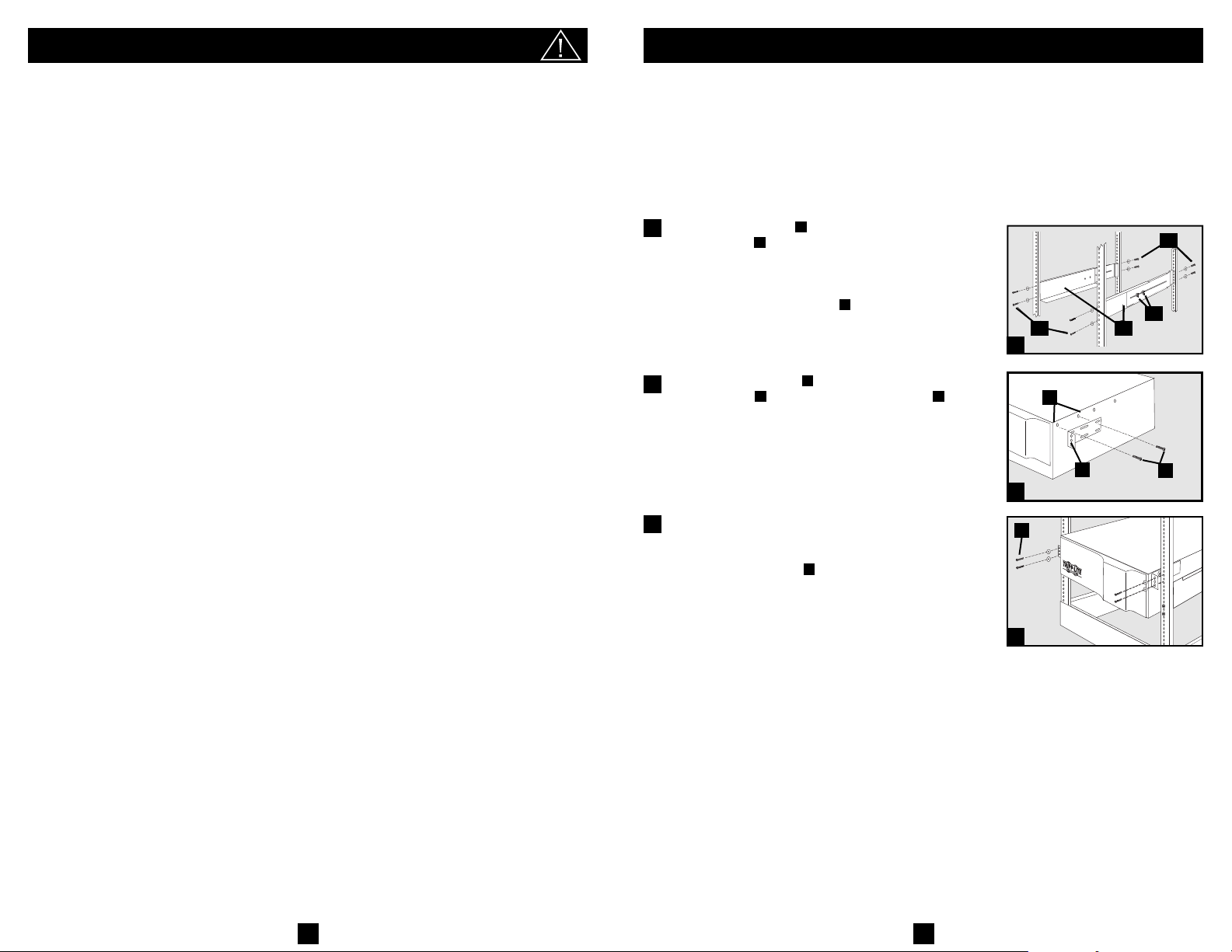
4-Post Rack Mounting
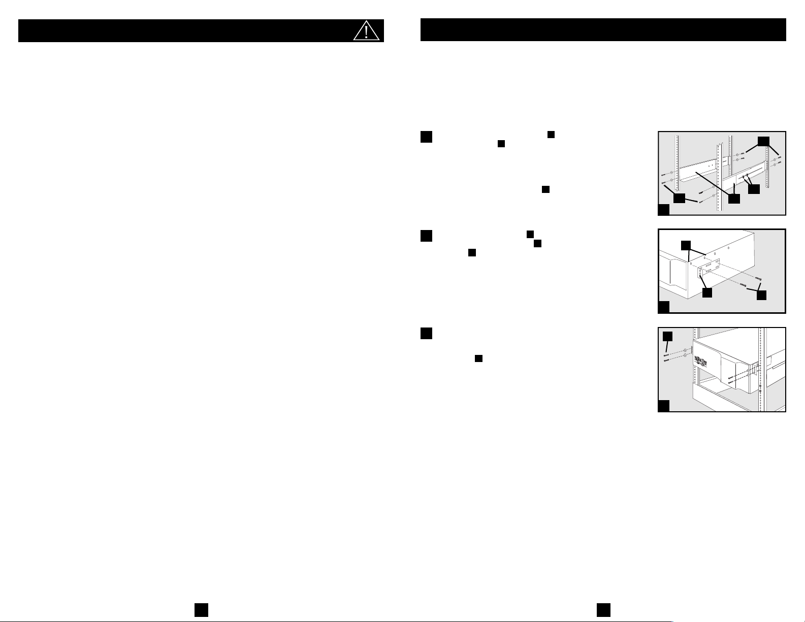
Loosen the wingnuts on each of the two adjustable
1
side supports ; adjust the length of the supports to
match the depth of your rack; tighten wingnuts. Mount
both side supports in the lowest space of your rack on
the inside surfaces of the rails with user-supplied #1032 rack bolts and washers . Note: Both support
ledges should face inward. The side supports’ front
and back holes are threaded and do not require nuts to
secure rack bolts.
Attach mounting ears to the front mounting holes
2
of your UPS using the screws provided . The
ears should face forward.
Using an assistant if necessary, lift your UPS and slide
3
it onto the mounting shelves (if your model includes
the shelves). Attach your UPS to the rack by using the
appropriate hardware through its mounting ears
and into the rack rails.
A
B
C
C
C
C
C
A
A
B
B
1
D
FE
E
D
F
2
G
G
3
2-Post Rack (Telecom) Mounting
If you mount 3U UPS models in 2-post racks, they require the addition of a Tripp Lite 2-Post
Rackmount Installation Kit (model: 2POSTRMKIT, sold separately). See Installation Kit owner’s
manual for installation procedure for 3U UPS models.
Tower Mounting
If you tower mount this UPS, it requires the addition of a Tripp Lite 2U to 9U tower stand
(model: 2-9USTAND, sold separately). See owner's manual for installation procedure.
2
3
Page 3
Quick Installation
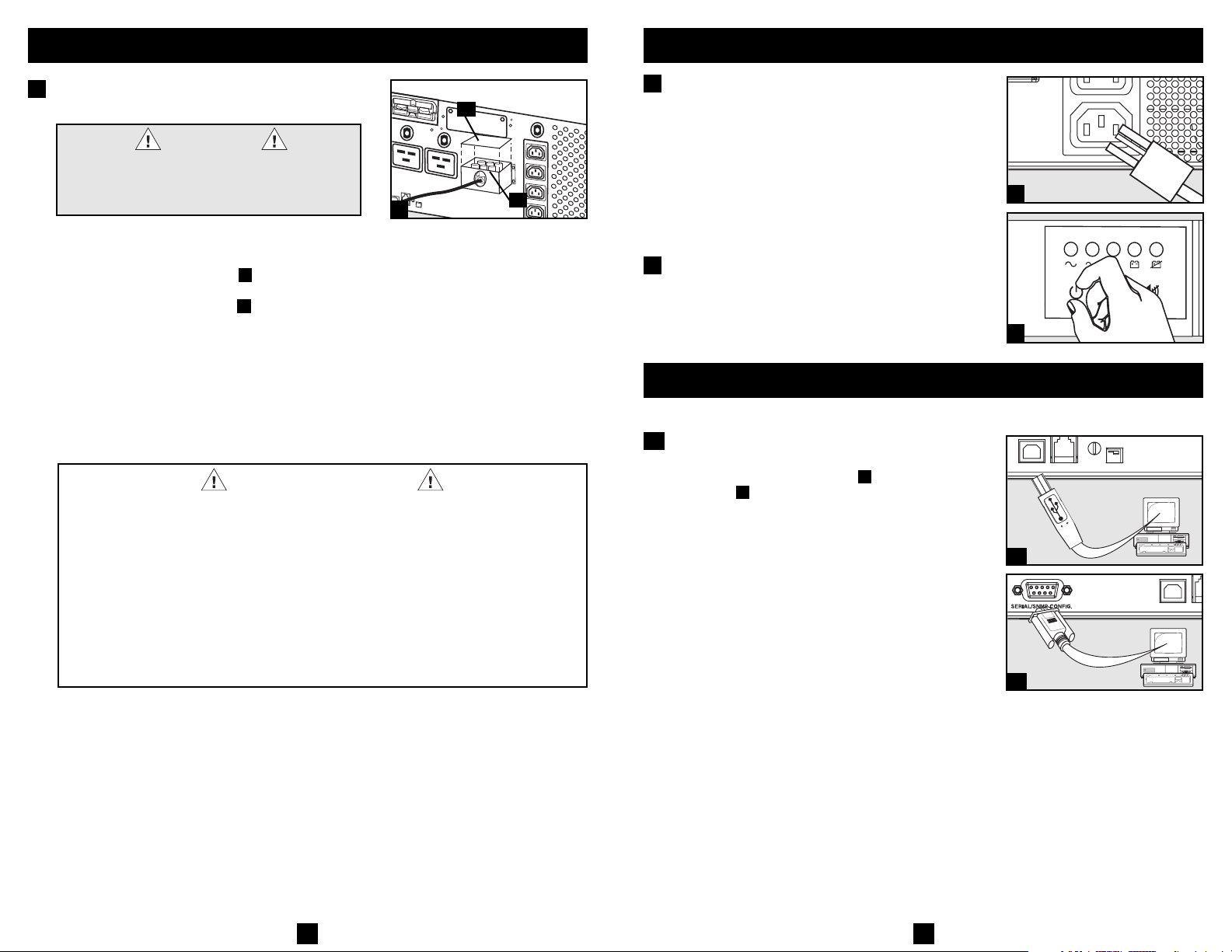
1
Hardwire the UPS System's input
terminals to a utility power source.
DANGER!
HIGH VOLTAGE! RISK OF SERIOUS INJURY OR
DEATH! FOR QUALIFIED ELECTRICIANS ONLY!
ELECTRICIANS MUST READ WARNINGS BELOW
AND IN SAFETY SECTION PRIOR TO INSTALLATION.
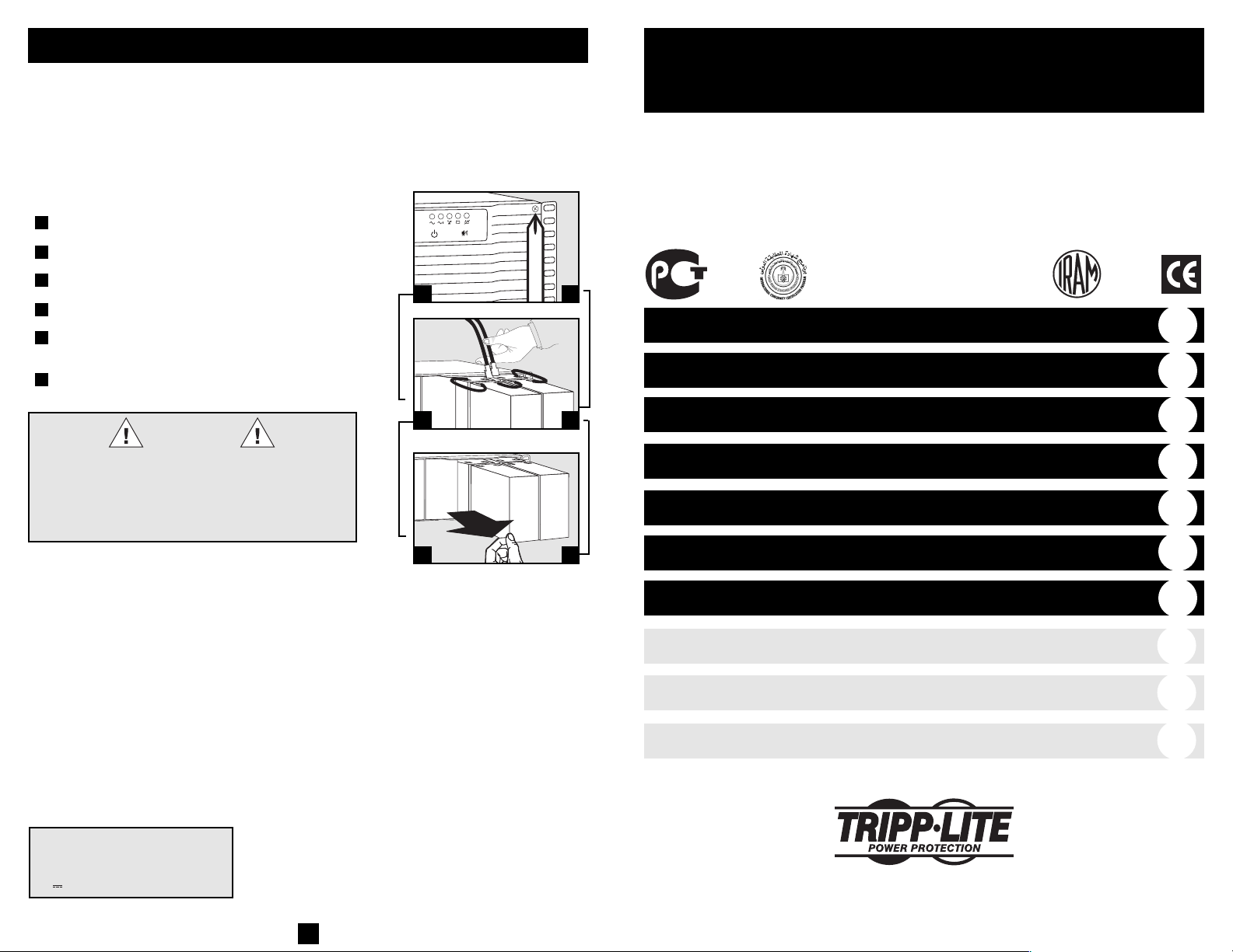
Before hardwiring, switch OFF the facility's circuit
breaker which is supplying power to the circuit the
UPS System will be connected to. Using a screwdriver, remove the top of the box covering the UPS
System's input terminals. Pass user-supplied cable
through the opening in the box and attach it to the
terminals. After hardwiring is complete, switch ON the
facility's circuit breaker which is supplying power to
the circuit the UPS System is connected to. Note! after
the UPS System is connected to a live utility power
source, the UPS (in “Standby” mode) will automatically charge its batteries,* but will not supply power to its
outlets until it is turned ON (see Step 3 below).
* The BATTERY CHARGE LED will be the only LED illuminated.
A
B
HARDWIRE WARNINGS!
• Wiring must be done by a qualified electrician.
• When making wiring connections, observe the cable connection regulations appropriate
to your area at all times. Be sure to install an easily accessible disconnect switch in your
installation wiring so you may cut off the UPS's AC input during fires and other
emergencies. Ensure that cables are fitted with cable sleeves and are secured by
connector clamps. Tighten connections with a torque of not less than 10 inch-pounds
(1.1 NM).
• Make sure that your equipment is properly grounded.
• Using cables of improper size may damage your equipment and cause fire hazards.
Choose appropriate cabling and protection circuits to make wiring connections (Ground
conductors must be the same size and type as the power conductors used).
1
A
Quick Installation
2
Plug your equipment into the UPS.*
Plug your equipment into the UPS using the additional power cord(s) that came with the UPS.
Note: Additional interconnection cords (C13 to C14) are available
from Tripp Lite. Call 773-869-1234 (Part # P004-006).
* Your UPS is designed to support only electronic equipment. You will
overload the UPS if the total VA ratings for all the equipment you connect
exceeds the UPS's Output Capacity. To find your equipment's VA rat-
B
ings, look on their nameplates. If the equipment is listed in amps, multiply the number of amps by 240 to determine VA. (Example: 1 amp ×
240 = 240 VA). If you are unsure if you have overloaded the UPS’s outlets,
see “OUTPUT LOAD LEVEL” LED description.
3
Turn the UPS ON.
Press and hold the “ON/OFF/STANDBY” button for
one second. The alarm will beep once briefly after one
second has passed. Release the button.
continued
2
3
Optional Installation
These connections are optional. Your UPS will function properly without these connections.
USB and RS-232 Serial
1
Communications
Use the included USB cable (see ) and/or DB9 serial
cable (see ) to connect the communication port on
your computer to the communication port of your
UPS. Install on your computer the Tripp Lite
PowerAlert Software appropriate to your computer’s
operating system. Consult your PowerAlert manual for
more information.
1b
1a
1a
1b
54
Page 4
Optional Installation
continued
Basic Operation
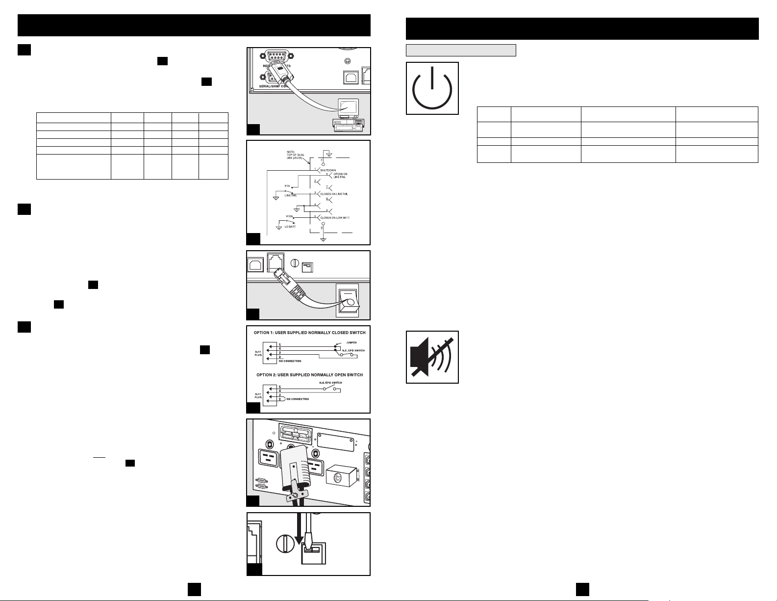
2
Relay Contact-Closure Connection
Use the included DB9 cable (see ) to connect spe-
2a
cialized electronic equipment to the relay contact-closure port on your UPS System. See diagram and
chart below to determine signals carried by this port.
Relay Contact Closure Chart
UPS Operating Conditions Pin 1 Pin 3 Pin 5 Pin 6
Low Battery * * CLOSED *
Battery OK * * OPEN *
AC Voltage Out of Range * CLOSED * OPEN
AC Voltage OK * OPEN * CLOSED
Shutdown > 0.6 mA * * *
* Inactive; may be in either state.
NOTE: Pins 4 and 9 are common signal reference pins.
3
EPO Port Connection
of current
into pin
This optional feature is only for those applications
which require connection to a facility’s Emergency
Power Off (EPO) circuit. When the UPS is connected
to this circuit, it enables emergency shutdown of the
UPS’s inverter.
Using the cable provided, connect the EPO port of
your UPS (see ) to a user-supplied normally closed or
3a
normally open switch according to the circuit diagram
3b
(see ). The EPO port is not a phone line surge suppressor; do not connect a phone line to this port.
4
External Battery Connection
All UPS models come with a robust internal battery
system; select models feature connectors (see ) that
accept optional external battery packs (sold separately
from Tripp Lite) to provide additional runtime. Adding
external batteries will increase recharge time as well as
runtime. See battery pack owner’s manual for complete
installation instructions. Make sure cables are fully
inserted into their connectors. Small sparks may result
during battery connection; this is normal. Do not connect
or disconnect battery packs when the UPS is running
on battery power.
If you connect any
Charge Level Switch (see ) to the down position. This
external batteries, set the Battery
4b
will increase your UPS’s charger output so the additional batteries charge faster. Note: the switch to the right of
the Battery Charge Level Switch is inactive and will not
affect UPS operation regardless of its position.
CAUTION! DO NOT set the Battery Charge Level Switch to the
down position without an external battery connected. There is a
risk of damaging the UPS’s internal battery system.
Buttons (Front Panel)
“ON/OFF/STANDBY” Button
2b
2a
2b
3a
4-5
4a
3b
4a
4b
6
When the UPS system is connected to a live AC utility power source, the UPS
System will operate in one of three modes: ON, OFF or STANDBY. Refer to
the chart below for UPS System operating characteristics within each mode.
Mode (when utility is present) (when utility is present or absent*) UPS Displays LEDs
ON Yes Yes Yes (variety of LEDs,
OFF No No No
STANDBY Yes No Yes ("BATTERY CHARGE"
UPS Charges Battery UPS Supplies Power to Outlets
depending on conditions)
LED only)
To place the UPS in the ON mode: First, have a qualified electrician connect
the UPS System to a utility power source as outlined in the Quick Installation
section. Once the utility power source is live, the UPS System will automatically enter STANDBY mode. Press and hold the “ON/OFF/STANDBY” button
for one second** and then release it to switch the UPS System from STANDBY mode to ON mode.
OPTIONAL: If the utility power source is not live, you can “cold-start” the
UPS System (i.e.: switch it directly from the OFF mode to the ON mode by
supplying power for a limited time from its batteries*) by pressing and holding the “ON/OFF/STANDBY” button for one second** and then releasing it.
To place the UPS in the OFF mode: With the UPS System in the ON mode
and receiving utility power, press and hold the “ON/OFF/STANDBY” button
for one second** and then release it to switch the UPS System from ON mode
to STANDBY mode. Switch OFF the facility's circuit breaker which is supplying power to the circuit the UPS System is connected to.
* If batteries are fully charged. ** The alarm will beep once briefly after the interval has passed.
“MUTE/TEST” Button
To Silence (or “Mute”) UPS Alarms: briefly press and release the
MUTE/TEST button.*
To Run a Self-Test: with your UPS connected to a live utility power source and
turned ON, press and hold the MUTE/TEST button for two seconds.* Continue
holding the button until the alarm beeps several times and the UPS performs a
self test. See “Results of a Self-Test” below. Note: you can leave connected equipment on during a self-test. Your UPS, however, will not perform a self-test if the
UPS is not turned on (see “ON/OFF/STANDBY” Button description).
Results of a Self-Test: the test will last approximately 10 seconds as the UPS
switches to battery to test its load capacity and battery charge.
• If the “OUTPUT LOAD LEVEL” LED remains lit red and the alarm continues to
sound after the test, the UPS’s outlets are overloaded. To clear the overload,
unplug some of your equipment and run the self-test repeatedly until the
“OUTPUT LOAD LEVEL” LED is no longer lit red and the alarm is no
longer sounding.
CAUTION! Any overload that is not corrected by the user immediately
following a self-test may cause the UPS to shut down and cease supplying
output power in the event of a blackout or brownout.
• If the “BATTERY WARNING” LED remains lit and the alarm continues to
sound after the test, the UPS batteries need to be recharged or replaced.
Allow the UPS to recharge continuously for 12 hours, and repeat the self-test.
If the LED remains lit, contact Tripp Lite for service. If your UPS requires
battery replacement, visit www.tripplite.com to locate the specific Tripp Lite
replacement battery for your UPS.
* The alarm will beep once briefly after the indicated interval has passed.
7
Page 5
Basic Operation
continued
Basic Operation
continued
Indicator Lights (Front Panel)
All Indicator Light descriptions apply when the UPS is connected to a live utility
power source and turned ON.
“POWER” LED: this green LED lights continuously when the UPS is ON and
supplying connected equipment with AC power from a utility source. The LED
flashes and an alarm sounds (4 short beeps followed by a pause) to indicate the
UPS is operating from its internal batteries during a blackout or severe
brownout. If the blackout or severe brownout is prolonged, you should save
files and shut down your equipment since internal battery power will eventually be depleted. See “BATTERY CHARGE” LED description below.
“VOLTAGE CORRECTION” LED: this green LED lights continuously
whenever the UPS is automatically correcting high or low AC voltage on the
utility line without the assistance of battery power. The UPS will also emit a
slight clicking noise. These are normal, automatic operations of the UPS, no
action is required on your part.
“OUTPUT LOAD LEVEL” LED: this multicolored LED indicates the
approximate electrical load of equipment connected to the UPS's AC outlets. It
will turn from green (light load) to yellow (medium load) to red (overload). If
the LED is red (either illuminated continuously or flashing), clear the overload
immediately by unplugging some of your equipment from the outlets until the
LED changes from red to yellow (or green). CAUTION! Any overload that is
not corrected by the user immediately may cause the UPS to shut down and
cease supplying output power in the event of a blackout or brownout.
“BATTERY CHARGE” LED: when the UPS is operating from utility power,
this LED indicates the approximate charge state of the UPS's internal batteries:
red indicates the batteries are beginning to charge; yellow indicates the batteries
are roughly midway through charging; and green indicates the batteries are fully
charged. When the UPS is operating from battery power during a blackout or
severe brownout, this LED indicates the approximate amount of energy (ultimately affecting runtime) which the UPS’s batteries will provide: red indicates
a low level of energy; yellow indicates a medium level of energy; and green
indicates a high level of energy. Since the runtime performance of all UPS batteries will gradually deplete over time, it is recommended that you periodically
perform a self-test (see MUTE/TEST Button description) to determine the energy
level of your UPS batteries BEFORE a blackout or severe brownout occurs.
During a prolonged blackout or severe brownout, you should save files and shut
down your equipment since battery power will eventually be depleted. When the
LED turns red and an alarm sounds continuously, it indicates the UPS's batteries
are nearly out of power and UPS shut down is imminent.
“BATTERY WARNING” LED: this LED lights red and an alarm sounds
intermittently after you complete a self test (See “MUTE/TEST” Button description) to indicate the UPS batteries need to be recharged or replaced. Allow the
UPS to recharge continuously for 12 hours, and repeat the self-test. If the LED
continues to light, contact Tripp Lite for service. If your UPS requires battery
replacement, visit www.tripplite.com to locate the specific Tripp Lite replacement
battery for your UPS.
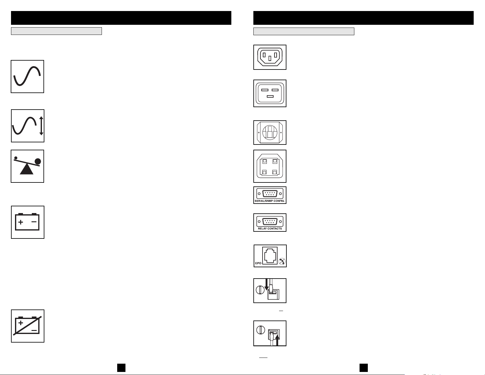
Other UPS Features (Rear Panel)
AC Receptacles: Your UPS features IEC320-C13 outlets, and select models
also feature IEC320-C19 outlets. These output receptacles provide your connected equipment with AC line power during normal operation and battery power
during blackouts and brownouts. The UPS protects equipment connected to
IEC320-C13/230V
IEC320-C19/230V
Charge Rate Setting (when
External Batteries are
connected)
Charge Rate Setting
(when External Batteries
e not connected)
ar
these receptacles against damaging surges and line noise. If you have a serial or
USB connection to your UPS, you can remotely reboot connected equipment by
turning the receptacles OFF and ON using Tripp Lite's PowerAlert Software.
Input Terminal block: Use these terminals to connect the UPS System to
utility power. Unscrew and remove the cover over the block for access.
Communications Ports (USB or RS-232): These ports connect your UPS to any
workstation or server. Use with Tripp Lite’s PowerAlert Software and included
cables to enable your computer to automatically save open files and shut down
equipment during a blackout. Also use PowerAlert Software to monitor a wide
variety of AC line power and UPS operating conditions. Consult your
PowerAlert Software manual or contact Tripp Lite Customer Support for more
information. See “USB and RS-232 Serial Communications” in the “Optional
Installation” section for installation instructions.
Relay Contact Interface Port: This female DB9 port sends contact-closure
signals to indicate line-fail and low battery status. See “Optional Installation”
section for installation instructions.
EPO (Emergency Power Off) Port: Your UPS features a EPO port that may
be used to connect the UPS to a contact closure switch to enable emergency
inverter shutdown. See Optional Connection.
Battery Charge Level Switch: Controls the UPS system’s battery charge rate.
If you connect any external batteries, set the Battery Charge Level Switch to the
down position. This will increase your UPS’s charger output so the additional batteries charge faster. Note: the switch to the right of the Battery Charge Level
Switch is inactive and will not affect UPS operation regardless of its position.
CAUTION! DO NOT set the Battery Charge Level Switch to the down
position without an external battery connected. There is a risk of damaging
the UPS’s internal battery system.
8
9
Page 6
Basic Operation
continued
Storage and Service
Accessory Slot: Remove the small cover panel from this slot to install optional
accessories to remotely monitor and control your UPS. Refer to your accessory’s
manual for installation instructions. Contact Tripp Lite Customer Support at
(773) 869-1234 for more information, including a list of available SNMP, network
management and connectivity products.
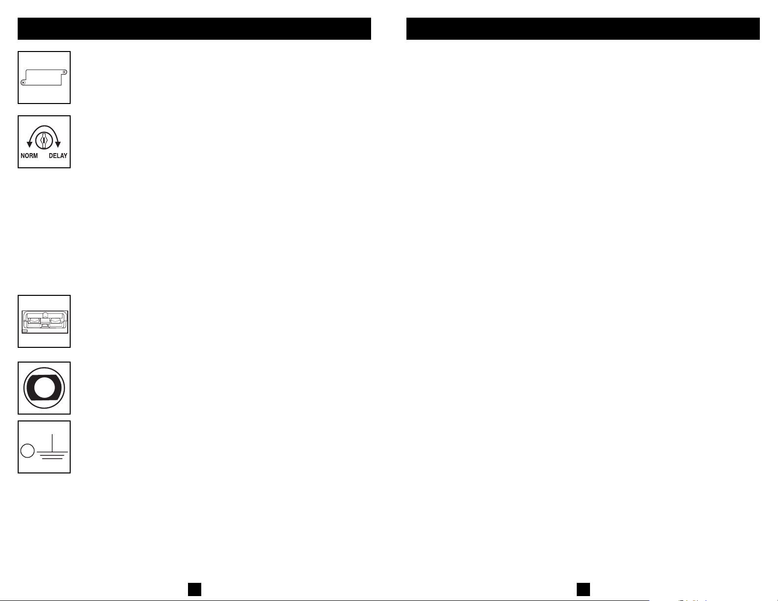
Power Sensitivity Adjustment: This dial is normally set fully counter-clockwise,
which enables the UPS to provide maximum protection against waveform distortions
in its AC input. When such distortion occurs, the UPS will normally switch to
providing sine wave power from its battery reserves for as long as the distortion
is present. In areas with poor utility power or where the UPS’s input power
comes from a backup generator, chronic waveform distortion could cause the
UPS to switch to battery too frequently, draining its battery reserves. You may
be able to reduce how often your UPS switches to battery due to moderate
waveform distortion by experimenting with different settings for this dial. As the
dial is turned clockwise, the UPS becomes more tolerant of variations in its input
power’s AC waveform. NOTE: The further the dial is adjusted clockwise, the greater
the degree of waveform distortion the UPS will allow to pass to connected equipment. When experimenting with different settings for this dial, operate connected equipment in a safe test mode so that the effect on the equipment of any waveform distortions in the UPS’s output can be evaluated without disrupting critical operations.
External Battery Connector: Use to connect Tripp Lite external battery packs for
additional runtime. Refer to instructions available with the battery pack for
complete connection information and safety warnings.
Storage
Before storing your UPS, turn it completely OFF. If you store your UPS for an extended period of time,
recharge the UPS batteries for 4 to 6 hours once every three months. Note: after you connect the UPS
to utility power, it will automatically begin charging its batteries. If you leave your UPS batteries discharged for an extended period of time, they will suffer a permanent loss of capacity.
Service
Before returning your UPS for service, follow these steps:
1. Review the installation and operation instructions in this manual to ensure that the service
problem does not originate from a misreading of the instructions. Also, check that the UPS
System’s circuit breaker(s) are not tripped. This is the most common cause of service inquiries
which can be easily remedied by following the resetting instructions in this manual.
2. If the problem continues, do not contact or return the UPS to the dealer. Instead, call Tripp Lite
at (773) 869-1233. A service technician will ask for the UPS's model number, serial number
and purchase date and will attempt to correct the problem over the phone.
3. If the problem requires service, the technician will issue you a Returned Material Authorization
(RMA) number, which is required for service. If you require packaging, the technician can
arrange to send you proper packaging. Securely pack the UPS to avoid damage during shipping.
Do not use Styrofoam beads for packaging. Any damages (direct, indirect, special, incidental
or consequential) to the UPS incurred during shipment to Tripp Lite or an authorized Tripp Lite
service center is not covered under warranty. UPS Systems shipped to Tripp Lite or an authorized
Tripp Lite service center must have transportation charges prepaid. Mark the RMA number on
the outside of the package. If the UPS System is within the 2-year warranty period, enclose a
copy of your sales receipt. Return the UPS for service using an insured carrier to the address
given to you by the Tripp Lite service technician.
Output Breaker(s): Protect your UPS from output overload. If one or more
breakers trip, remove some of the load on the circuit(s), then reset them by
pressing the breaker switch(es) in.
Ground Screw: Use this to connect any equipment that requires a chassis ground.
10
11
Page 7
Battery Replacement
Battery replacement should be performed only by authorized service personnel using the same number and type of batteries (sealed Lead-Acid). Under normal conditions, the original batteries in your
UPS will last many years. See Safety section before replacing batteries. The batteries are designed
for hot-swap replacement (i.e. leaving the UPS in ON mode), but some qualified service personnel
may wish to put the UPS in the OFF mode and disconnect equipment before proceeding.
Procedure
1
Remove Front Panel and Battery Holding Plate
2
Disconnect Batteries
3
Remove/Dispose of Batteries
4
Add Batteries
5
Connect Batteries
Attach connectors: black-to-black and red-to-red.
6
Replace
Front Panel
®
UPS
RO
P
MART
S
1
6
5
4
WARNING!
Batteries can present a risk of electrical shock and burn
from high short-circuit current resulting in serious
injury or death. Battery terminals are in close proximity
to UPS cabinet and special care must be taken to avoid
shorting the batteries including not touching metal
cabinet and battery terminals simultaneously.
2
3
Manual del propietario
SmartPro®3U Rackmount
(5000VA)
Sistemas de UPS Inteligentes e Interactivos en Línea
• 230V Entrada/Salida
• Opciones de Operación Extendidas
Instrucciones de seguridad importantes
Montaje
Instalación rápida
Instalación opcional
Operación básica
Almacenamiento y servicio
14
15
16
17
19
23
The policy of Tripp Lite is one of continuous improvement. Specifications are subject to change without notice.
Regulatory Compliance Identification Numbers
For the purpose of regulatory compliance certifications and identification, your Tripp Lite product has been assigned a unique series number. The series number
can be found on the product nameplate label, along with all required approval markings and information. When requesting compliance information for this product,
always refer to the series number. The series number should not be confused with the marking name or model number of the product.
This product designed and engineered in the USA.
Note on Labeling
Two symbols are used on the label.
V~ : AC Voltage
V : DC Voltage
12
Reemplazo de batería
English
Français
Pусски
é
1111 W. 35th Street Chicago, IL 60609 USA
Soporte al cliente: (773) 869-1234 • www.tripplite.com
Copyright ©2004 Tripp Lite. Todos los derechos reservados. SmartPro®es una marca comercial registrada de Tripp Lite.
24
1
25
37
Page 8
Instrucciones de seguridad importantes
Montaje
GUARDE ESTAS INSTRUCCIONES
Este manual contiene importantes instrucciones que deben seguirse durante la instalación, operación y el
almacenamiento de todos los UPS de Tripp Lite. La no observancia de estas advertencias anulará su garantía.
Advertencias sobre la ubicación del UPS
• Tenga cuidado al levantar el UPS. Debido al gran peso de los UPS para montaje en bastidor, se requieren
por lo menos dos personas para que le ayuden a levantarlos e instalarlos.
• Instale su UPS bajo techo, lejos de la humedad, el calor, el polvo o la luz solar directa.
• Para un mejor funcionamiento, la temperatura ambiente cerca de su UPS debe estar entre 0° C y 40° C
(32° F - 104° F)
• Deje una cantidad adecuada de espacio alrededor de todos los lados del UPS para sua adecuada
ventilación. No obstruya sus respiraderos ni las aberturas de ventilación.
Advertencias sobre la conexión del UPS
• El UPS contiene su propia fuente de energía (batería). Los terminales de salida pueden estar con energía
incluso cuando el UPS no está conectado a un suministro de corriente alterna.
Advertencias sobre la conexión de equipos
• No utilice sistemas UPS de Tripp Lite para aplicaciones de soporte de vida en las que un funcionamiento
defectuoso o una falla del UPS pudiera causar un mal funcionamiento o una alteración importante en el
funcionamiento de un dispositivo de soporte de vida.
• No conecte supresores de sobretensiones ni cordones de extensión a la salida de su UPS. Esto puede
sobrecargarlo y anular su garantía y la del supresor de sobretensiones.
Advertencias sobre la batería
• Las baterías presentan un peligro de choque eléctrico y quemaduras debido a las altas corrientes de cortocircuito. Observe las precauciones apropiadas. No deseche las baterías en un incinerador. No abra el UPS
ni las baterías. No ponga los terminales de la batería en corto o en puente con ningún objeto. Apague y
desconecte el UPS antes de reemplazar la batería. Use herramientas con mangos aislados. No hay piezas
que el usuario pueda reparar dentro del UPS. El reemplazo de baterías debe ser realizado solamente por
personal de servicio autorizado usando el mismo número y tipo de baterías (plomo-ácido, selladas). Las
baterías son reciclables. Consulte la reglamentación local para los requisitos de disposición de desechos;
en los EE.UU. llame al 1-800-SAV-LEAD o al 1-800-8-BATTERY (1-800-8-228-8379) o visite
www.rbrc.com para obtener información sobre el proceso de reciclaje. Tripp Lite ofrece una línea
completa de cartuchos de reemplazo de batería para UPS (R.B.C.) Visite la página web de Tripp Lite en
www.tripplite.com para localizar la batería de reemplazo específica para su UPS.
• Durante el reemplazo de baterías en operación (hot-swap), el UPS no proporcionará energía de respaldo
en el caso de una falla del servicio eléctrico u otras interrupciones de energía.
• No opere el UPS sin baterías.
• Al agregar bancos de baterías externas, sólo emplee bancos recomendados por Tripp Lite del voltaje y
tipo correctos. No conecte ni desconecte bancos de baterías cuando el UPS esté funcionando con energía
de las baterías.
Monte su equipo en un bastidor de 2 o 4 postes (vea la siguiente página para información sobre el montaje de 2
postes). El usuario debe determinar la idoneidad de los materiales y accesorios, así como de los procedimientos antes
del montaje. Si los materiales y procedimientos no son adecuados para su aplicación, contacte con el fabricante
de su bastidor. Los procedimientos descritos en este manual son para bastidores comunes y de tipo caja y podrían
no ser apropiados para todas las aplicaciones.
Montaje en bastidor de 4 postes
Afloje las tuercas de mariposa en los dos soportes lat-
1
erales ajustables ; ajuste la longitud de los soportes para
que sea igual a la profundidad de su bastidor; apriete las tuercas de mariposa. Monte ambos soportes laterales en el espacio más bajo de su bastidor en la superficie interna de los
rieles, con los pernos para bastidor #10-32 y las arandelas
suministrados por el usuario . Nota: Ambos bordes de
apoyo deben mirar hacia adentro. Los agujeros delantero y
posterior de los soportes laterales son roscados y no necesitan tuercas para asegurar los pernos del bastidor.
Fije las orejas de montaje a los agujeros de montaje de la
2
parte delantera de su UPS usando los tornillos suministrados . Las orejas deben mirar hacia adelante.
B
E
A
C
C
C
C
C
A
A
B
B
1
C
D
D
C
E
2
Utilizando la ayuda de otra persona, levante su UPS y
3
colóquelo sobre los estantes de apoyo (si su modelo los
incluye.) Fije su UPS al bastidor usando los accesorios suministrados a través de las orejas de montaje y dentro de los
rieles del bastidor.
F
F
3
Montaje en bastidor de 2 postes
Si monta un modelo de UPS de 3U en bastidores de 2 postes, necesitará agregar un kit de instalación para montaje
en bastidor de 2 postes de Tripp Lite (modelo: 2POSTRMKIT, vendido por separado) Vea el manual del propietario
del kit para conocer el procedimiento de instalación en los modelos de 3U.
Montaje de torre
Si monta en torre este UPS, debe agregar un pedestal de torre Tripp Lite de 2U a 9U (modelo: 2-9USTAND, vendido por separado). Consulte el procedimiento de instalación en el manual del propietario.
14
15
Page 9

Instalación rápida
1
Conecte los terminales de entrada del UPS a una fuente de
energía de la red.
¡PELIGRO!
¡ALTO VOLTAJE! ¡RIESGO DE LESIONES GRAVES O
MUERTE! ¡SÓLO PARA ELECTRICISTAS
EXPERIMENTADOS! LOS ELECTRICISTAS DEBEN
LEER LAS ADVERTENCIAS DE LA SECCIÓN
SEGURIDAD ANTES DE LA INSTALACIÓN.
Antes de cablear, APAGUE el interruptor automático que
suministra energía al circuito al que estará conectado el UPS.
Con un destornillador, retire la parte superior de la caja
que cubre los terminales de entrada del UPS. Pase el cable
suministrado por el usuario a través de la abertura en la caja
B
y conéctelo a los terminales. Después de completar el
cableado, ENCIENDA el interruptor automático que suministra energía al circuito al que está conectado el UPS. ¡Nota!
después de que el UPS esté conectado a una fuente de energía
de la red con tensión, el UPS -en modo “Standby”
(“Reserva”), cargará automáticamente sus baterías,* pero no
suministrará energía a sus salidas hasta que sea ENCENDIDO (vea el Paso 3 más adelante).
* El LED BATTERY CHARGE (CARGA DE BATERÍA) será el único
iluminado.
¡ADVERTENCIAS DE CABLEADO!
• El cableado debe ser realizado por un electricista calificado.
• Al conectar conductores, observe en todo momento los reglamentos de conexión de cables
adecuados para su área. Asegúrese de instalar un interruptor de desconexión fácilmente accesible en
su cableado de modo que pueda cortar la entrada de corriente alterna al UPS durante incendios y
otras emergencias. Asegúrese que los cables cuenten con mangas y estén asegurados con
abrazaderas de conectores. Apriete las conexiones con un torque no menor que 10 libras-pulgada
(1.1 Nm)
• Asegúrese que su equipo esté puesto a tierra adecuadamente.
• El uso de cables de calibre inadecuado puede dañar su equipo y causar riesgos de incendio. Elija
cables y circuitos de protección adecuados para realizar las conexiones de cableado (Los
conductores de tierra deben ser del mismo tipo y calibre que los conductores de energía utilizados).
1
A
A
Instalación rápida
2
Enchufe su equipo en el UPS.*
Usando los demás cables eléctricos que se adjuntaron con el
UPS.
Nota: Se pueden obtener cables de interconexión adicionales (C13 a
través de Tripp Lite. Llame al 773-869-1234 (Repuesto # P004-006).
* Su UPS sólo está diseñado para dar soporte a equipos electrónicos.
Usted sobrecargará el UPS si el total del índice de los voltios/ amperios para todo el equipo excede la capacidad de salida del UPS. Para
B
averiguar el índice de voltios/amperios de su equipo, búsquelos en la
placa del fabricante.Si el equipo está enumerado en amperios, multiplique el número de amperios por 240 para determinar los
voltios/amperios (Por ejemplo: 1 amp x 240 = 240 voltios/amperios).
Si no está seguro de haber sobrecargado las tomas eléctricas del
UPS, vea la descripción sobre el indicador “NIVEL DE SOBRECARGA DE SALIDA”.
3
Encienda el UPS.
Presione y mantenga presionado el botón “ON/OFF/STANDBY”
(Encendido/Apagado/Reserva) durante un segundo. La alarma emitirá un pitido brevemente después de pasado un
segundo. Suelte el botón.
(continúa)
C14)
2
3
Instalación opcional
Estas conexiones son opcionales. Su UPS funcionará correctamente sin ellas.
1
Comunicaciones USB y serie RS-232
Use el cable USB incluido (vea ) y/o el cable serie DB9
1b
(vea ) para conectar el puerto de comunicaciones de su
computadora al puerto de comunicaciones de su UPS. Instale
en su computadora el software PowerAlert de Tripp Lite
apropiado para su sistema operativo. Consulte su manual de
PowerAlert para mayor información.
1a
1a
16
1b
17
Page 10

Instalación opcional
(continúa)
Operación básica
Conexión de cierre de contacto por relé
2
Use el cable DB9 incluido (ref. ) para conectar equipo
electrónico especializado al puerto de transmisión y cierre de
contacto en su Sistema UPS. Vea el diagrama y la tabla
2a
2b
de abajo para determinar las señales transportadas por este
puerto.
Tabla de cierre de contactos de relé
Condiciones de
operación del UPS Pin 1 Pin 3 Pin 5 Pin 6
Batería baja * * CERRADO *
Batería bien * * ABIERTO *
Voltaje CA fuera * CERRADO * ABIERTO
de rango
Voltaje CA bien * ABIERTO * CERRADO
Apagado > 0.6 mA de * * *
* Inactivo; Puede estar en cualquier estado.
NOTA: Los pines 4 y 9 son una referencia común de señal.
Conexión de puerto EPO
3
Esta característica opcional es sólo para aquellas aplicaciones que requieran una conexión al circuito de desconexión de emergencia (EPO) de la instalación Cuando el UPS
está conectado a este circuito, permite el apagado de emergencia del inversor del UPS.
Usando el cable suministrado, conecte el puerto EPO de su
UPS (vea ) a un contacto normalmente cerrado o normalmente abierto suministrado por el usuario, de acuerdo con el
diagrama del circuito (vea ) El puerto EPO no es un
supresor de sobretensiones de línea telefónica; no conecte
una línea telefónica en este puerto.
4
Conexión de batería externa
Todos los modelos de UPS incluyen un robusto sistema de
batería interna; los modelos exclusivos tienen conectores
4a
(ver ) que permiten bancos de baterías externas
opcionales (vendidos por separado por Tripp Lite) para proporcionar tiempo de respaldo adicional. Agregando baterías
externas aumentará el tiempo de recarga así como el tiempo
de respaldo. Consulte el manual del propietario del banco de
baterías para obtener las instrucciones completas de instalación. Asegúrese que los cables estén introducidos completamente en sus conectores. Pueden producir pequeñas chispas
durante la conexión de la batería; esto es normal. No conecte ni
desconecte bancos de baterías cuando el UPS esté funcionando con energía de las baterías.
Si conecta alguna batería externa, fije el Interruptor de nivel
de carga de batería (ver ) en la posición de abajo. Esto
aumentará la salida del cargador del UPS a fin de cargar más
rápido baterías adicionales. Nota: El interruptor a la derecha
del interruptor de nivel de carga está inactivo y no afectará la
operación del UPS, independientemente de su posición.
¡PRECAUCIÓN! NO fije el Interruptor de nivel de carga de
batería en la posición de abajo sin que haya conectada alguna batería externa. Podría dañarse el sistema de la batería
interna del UPS.
corriente en el pin
3a
3b
4b
18
18
2a
Diagrama de interfaz de cierre de contactos de relé
2b
3a
4-5
3b
4a
4b
Botones (Panel frontal)
Botón “ON/OFF/STANDBY” (Encendido/Apagado/Reserva)
Cuando el UPS está conectado a una fuente de energía de CA de la red con tensión, oper-
ará en uno de los tres modos siguientes: ON, OFF o STANDBY (ENCENDIDO, APAGADO o RESERVA) Consulte las características de operación del UPS en la tabla siguiente dentro de cada modo.
Modo de la red) (haya energía de la red o no*) LEDs en el UPS
ENCENDIDO Sí Sí Sí (varios LEDs,
APAGADO No No No
RESERVA Sí No Sí (sólo el LED
Para colocar el UPS en modo ON (ENCENDIDO): En primer lugar, haga que un electricista calificado conecte el UPS a una fuente de energía de la red como se indica en la
sección Instalación rápida. En cuanto la fuente de energía de la red tenga tensión, el UPS
entrará automáticamente al modo STANDBY (RESERVA). Presione y mantenga presionado el botón “ON/OFF/STANDBY” (ENCENDIDO/APAGADO/RESERVA)
durante un segundo** y luego suéltelo para cambiar el UPS del modo STANDBY
(RESERVA) al modo ON (ENCENDIDO).
OPCIONAL: Si la fuente de energía de la red no tiene tensión, puede “arrancar en
frío” el UPS (es decir, pasar directamente del modo OFF (APAGADO) al modo ON
(ENCENDIDO) suministrando energía por un tiempo limitado de sus baterías*) presionando y manteniendo presionado el botón “ON/OFF/STANDBY” (ENCENDIDO/APAGADO/RESERVA) durante un segundo** y luego soltándolo.
Para colocar el UPS en modo OFF (APAGADO): Con el UPS en modo ON (ENCENDIDO) y recibiendo energía de la red, presione y mantenga presionado el botón
“ON/OFF/STANDBY” (ENCENDIDO/APAGADO/RESERVA) durante un segundo** y
luego suéltelo para cambiar el UPS de modo ON (ENCENDIDO) a modo STANDBY
(RESERVA). APAGUE el interruptor automático que suministra energía al circuito al que
se conectará el UPS.
* Si las baterías están completamente cargadas. ** La alarma emitirá un pitido brevemente después de pasado el intervalo.
Botón “MUTE/TEST” (SILENCIO/PRUEBA)
Para silenciar las alarmas UPS: Con su UPS conectado a una fuente de energía de la
red con tensión, presione y mantenga presionado el botón MUTE/TEST (SILENCIO/
PRUEBA) durante dos segundos.*
Para ejecutar una auto-prueba: Con su UPS conectado y encendido, presione y mantenga
presionado el botón MUTE/TEST (Silencio/Prueba) por dos segundos.*Siga presionando el
botón hasta que la alarma suene varias veces y el UPS realice una auto-prueba. Vea
“Resultados de una auto-prueba” más abajo. Nota: Puede dejar equipos conectados durante
una auto-prueba. Sin embargo, el UPS, no realizará una auto-prueba si no está encendido
(vea la descripción del Botón “ON/OFF/STANDBY”).
Resultados de una auto-prueba: La prueba durará cerca de 10 segundos mientras el
UPS conmuta a batería para probar su capacidad de carga y la recarga de la batería.
• Si el LED “OUTPUT LOAD LEVEL” (NIVEL DE CARGA DE SALIDA) permanece encendido rojo y la alarma continúa sonando después de la prueba, las salidas
del UPS están sobrecargadas. Para eliminar la sobrecarga, desconecte algo de su
equipo y ejecute la auto-prueba repetidamente hasta que el LED ya no esté encendido
rojo y la alarma ya no esté sonando.
¡PRECAUCIÓN! Cualquier sobrecarga que no sea corregida por el usuario
inmediatamente después de una auto-prueba puede causar que el UPS se apague
y deje de suministrar energía de salida en el caso de una falla del servicio eléctrico
o una baja de voltaje.
• Si el LED “BATTERY WARNING” (ADVERTENCIA DE BATERÍA) sigue encendido
y la alarma continúa sonando después de la prueba, las baterías del UPS deben recargarse
o reemplazarse. Permita que el UPS se recargue continuamente por 12 horas y repita
la auto-prueba. Si el LED permanece encendido, contacte con Tripp Lite para obtener
servicio. Si su UPS requiere el reemplazo de su batería, visite www.tripplite.com para
localizar la batería de reemplazo Tripp Lite específica para su UPS.
* La alarma emitirá un pitido brevemente después de pasado el intervalo indicado.
El UPS carga la batería El UPS suministra
(cuando hay energía energía a las salidas Se encienden
según las condiciones)
"BATTERY CHARGE"
(CARGA DE BATERÍA))
19
Page 11

Operación básica
(continúa)
Operación básica
(continúa)
Luces indicadoras (Panel frontal)
Todas las descripciones de luces indicadoras se aplican cuando el UPS está conectado a
una fuente de energía de la red con tensión.
LED “POWER” (ALIMENTACIÓN): Este LED verde se enciende permanentemente
cuando el UPS está encendido y proporcionando energía de CA al equipo conectado desde
el suministro de red. El LED destella y una alarma suena (4 pitidos cortos seguidos de una
pausa) para indicar que el UPS está operando con sus baterías internas durante una falla
del servicio eléctrico o una severa baja de voltaje. Si la falla o la baja de voltaje es muy
prolongada, debe guardar sus archivos y apagar su equipo ya que la energía de la batería
interna finalmente se agotará. Vea la descripción del LED “BATTERY CHARGE”
(CARGA DE BATERÍA)
LED “VOLTAGE CORRECTION” (CORRECCIÓN DE VOLTAJE): Este LED
verde se enciende en forma permanente cuando el UPS está corrigiendo automáticamente
el voltaje de CA alto o bajo en la línea de la red sin la ayuda de energía de baterías. El
UPS también emitirá un ligero clic. Estas son operaciones normales y automáticas del
UPS y no requieren de ninguna acción de su parte.
LED “OUTPUT LOAD LEVEL” (NIVEL DE CARGADE SALIDA): Este LED multicolor indica la carga eléctrica aproximada del equipo conectado a las salidas de CA del
UPS. Se encenderá desde verde (carga ligera) a amarillo (carga media) y a rojo (sobrecarga) Si el LED está rojo (ya sea iluminado permanentemente o destellando), elimine la
sobrecarga de inmediato desconectando algo de su equipo de las salidas hasta que el LED
cambie de rojo a amarillo (o verde). ¡PRECAUCIÓN! Cualquier sobrecarga que no sea
corregida por el usuario inmediatamente puede causar que el UPS se apague y deje de suministrar energía de salida en el caso de un falla del servicio eléctrico o una baja de voltaje.
LED “BATTERY CHARGE” (CARGA DE BATERÍA): Cuando el UPS opera con la
energía de la red, este LED indica el estado aproximado de carga de las baterías internas
del UPS; el rojo indica que las baterías están comenzando a cargarse; el amarillo indica
que las baterías están aproximadamente a media recarga; y el verde indica que las baterías
están totalmente cargadas. Cuando el UPS opera con energía de las baterías durante una
falla del servicio eléctrico o una baja de voltaje severa, este LED indica la cantidad aproximada de energía (que a fin de cuentas afecta el tiempo de respaldo) que proporcionarán
las baterías del UPS; el rojo indica un bajo nivel de energía, el amarillo un nivel mediano
y el verde un nivel alto de energía. Ya que el rendimiento del tiempo de respaldo de todas
las baterías del UPS se reducirá gradualmente, se recomienda realizar una auto-prueba
periódicamente (vea la descripción del botón MUTE/TEST (SILENCIO/PRUEBA)) para
determinar el nivel de energía de las baterías de su UPS ANTES de que ocurra una falla
del servicio eléctrico o una baja de voltaje severa. Durante una falla prolongada o una severa
baja de voltaje, debe guardar sus archivos y apagar su equipo ya que la energía de baterías
se agotará finalmente. Cuando el LED se enciende rojo y una alarma suena en forma continua,
indica que las baterías del UPS están casi sin energía y es inminente que el UPS se apague.
LED “BATTERY WARNING” (ADVERTENCIA DE BATERÍA): Este LED se
enciende rojo y una alarma suena en forma intermitente después de iniciar una auto-prueba
(vea la descripción del botón “MUTE/TEST” (SILENCIO/PRUEBA)) para indicar que
las baterías del UPS deben ser recargadas o reemplazadas. Permita que el UPS se recargue
continuamente por 12 horas y repita la auto-prueba. Si el LED sigue encendido, contacte
con Tripp Lite para que le brinden servicio. Si su UPS requiere el reemplazo de su batería,
visite www.tripplite.com para localizar la batería de reemplazo Tripp Lite específica para
su UPS.
Otras funciones del UPS (Panel posterior)
Tomas de CA: Su UPS tiene salidas IEC320-C13, y ciertos modelos escogidos también cuentan
con salidas IEC320-C19. Estas salidas proporcionan energía de la línea de corriente alterna a su
equipo conectado durante operación normal, y energía de baterías durante fallas del servicio
eléctrico y bajas de voltaje. El UPS protege al equipo conectado a estas tomas contra
IEC320-C13/230V
IEC320-C19/230V
Ajuste de velocidad de
carga (con baterías
externas conectadas)
Ajuste de velocidad de
carga (sin baterías
externas conectadas)
sobretensiones perjudiciales y ruido en la línea. Si tiene una conexión serie o USB a su
UPS, puede reiniciar en forma remota el equipo conectado desactivando las salidas y
activándolas nuevamente, usando el software PowerAlert de Tripp Lite. Vea las instrucciones del software para más detalles.
Bloque de terminales de entrada: Use estos terminales para conectar el UPS a la energía
de la red. Destornille y retire la cubierta del bloque para tener acceso.
Puertos de comunicaciones (USB o RS-232): Estos puertos conectan su UPS a
cualquier estación de trabajo o servidor. Úselos con el software PowerAlert de Tripp Lite
y los cables incluidos para permitir que su computadora guarde automáticamente los
archivos abiertos y apague el equipo durante una falla del servicio eléctrico. También utilice
PowerAlert para vigilar una amplia variedad de condiciones de operación de la energía de
la línea de CA y del UPS. Consulte su manual de PowerAlert o contacte con el Soporte
al cliente de Tripp Lite para mayor información. Consulte “Comunicaciones USB y serie
RS-232” en la sección “Instalación opcional” para obtener la información sobre las
instrucciones de instalación.
Puerto de interfaz de contacto de relé: Este puerto DB9 hembra envía señales de cierre
de contacto para indicar una falla en la línea y un estado de batería baja. Consulte las
instrucciones de instalación en la sección “Instalación opcional”.
Puerto EPO (Desconexión de emergencia): Su UPS tiene un puerto EPO que puede usarse
para conectar el UPS a un contacto de cierre para permitir el apagado de emergencia del
inversor. Consulte Conexión opcional.
Interruptor de nivel de carga de batería: Controla la velocidad de carga de baterías del
UPS. Si conecta alguna batería externa, fije el Interruptor de nivel de carga de batería en
la posición de abajo. Esto aumentará la salida del cargador del UPS a fin de cargar más
rápido baterías adicionales. Nota: El interruptor a la derecha del interruptor de nivel de
carga está inactivo y no afectará la operación del UPS, independientemente de su posición. ¡PRECAUCIÓN! NO fije el Interruptor de nivel de carga de batería en la posición
de abajo sin que haya conectada alguna batería externa. Podría dañarse el sistema de la
batería interna del UPS.
20
21
Page 12

Operación básica
(continúa)
Almacenamiento y servicio
Ranura auxiliar: Retire el pequeño panel de cubierta de esta ranura para instalar los
accesorios opcionales para vigilancia y control de su UPS en forma remota. Consulte el
manual de sus accesorios para instrucciones de instalación. Contacte con el Soporte al
cliente de Tripp Lite al (773) 869-1234 para mayor información, incluyendo una lista de
productos disponibles para SNMP, administración de red y conectividad.
Ajuste de sensibilidad de energía: Este dial está fijado normalmente totalmente contra
el sentido del reloj, lo que permite que el UPS proporcione una protección máxima contra
distorsiones de la forma de onda en su entrada de CA. Cuando ocurren dichas distorsiones,
normalmente el UPS conmutará para proporcionar una onda sinusoidal de energía de sus
baterías de reserva por tanto tiempo como la distorsión continúe. En áreas con un suministro de energía de la red de baja calidad, o donde la energía de entrada del UPS provenga de un generador de respaldo, la distorsión crónica de la forma de onda puede causar
que el UPS conmute a alimentación por baterías con demasiada frecuencia, agotando sus
baterías de reserva. Es posible que reduzca la frecuencia con que su UPS conmuta a
baterías moderando la distorsión de la forma de onda experimentando con diferentes ajustes
para este dial. A medida que el dial es girado en el sentido del reloj, el UPS se vuelve más
tolerante a las variaciones en la forma de onda de la energía de la CA de entrada. NOTA: A
mayor ajuste del dial en el sentido del reloj, mayor será el grado de distorsión de la forma
de onda que el UPS permitirá pasar al equipo conectado. Al experimentar con diferentes
ajustes para este dial, opere el equipo conectado en un modo de prueba seguro, de modo
que el efecto de cualquier distorsión de forma de onda en la salida del UPS sobre el
equipo pueda evaluarse sin desestabilizar ninguna operación crítica.
Conector de la batería externa (Sólo en modelos exclusivos): Úselo para conectar los
bancos de baterías externas de Tripp Lite para obtener tiempo de respaldo adicional.
Consulte las instrucciones incluidas con el banco de baterías para obtener información
completa sobre la conexión y las advertencias de seguridad.
Almacenamiento
Antes de almacenar su UPS, apáguelo completamente. Si va a almacenar su UPS por un tiempo prolongado,
recargue las baterías del UPS durante 4 a 6 horas, una vez cada tres meses. Nota: Después de que conecte el UPS
a la energía de la red, comenzará automáticamente a cargar sus baterías. Si deja descargadas las baterías del UPS
durante un período prolongado de tiempo, sufrirán una pérdida de capacidad permanente.
Servicio
Antes de enviar su UPS para que le presten servicio, siga los siguientes pasos:
1. Verifique las instrucciones de instalación y operación en este manual para asegurarse que el problema de
servicio no sea causado por una mala interpretación de las instrucciones. Además, verifique que los interruptores automáticos del UPS no hayan sido disparados. Esta es la causa más común de pedidos de servicio
que pueden ser solucionados fácilmente siguiendo las instrucciones de restablecimiento en este manual.
2. Si el problema continúa, no contacte con el distribuidor ni devuelva el UPS. En su lugar, llame a Tripp Lite
al (773) 869-1233. Un técnico de servicio le pedirá el modelo, número de serie y fecha de compra del UPS
y tratará de resolver el problema a través del teléfono.
3. Si el problema requiere servicio, el técnico le emitirá un número de Autorización de devolución de mercadería
(RMA), necesario para que le presten servicio. Si requiere embalaje, el técnico puede hacer arreglos para
que le envíen el embalaje adecuado. Empaque el UPS firmemente para evitar daños durante el despacho. No
use camas de Styrofoam para embalaje. Cualquier daño (directo, indirecto, especial, accidental o resultante)
al UPS producido durante el despacho a Tripp Lite o a un centro autorizado de servicio Tripp Lite no está
cubierto por la garantía. Los sistemas UPS enviados a Tripp Lite o a algún centro de servicio autorizado de
Tripp Lite deben tener los cargos de transporte prepagados. Marque el número RMAen la parte externa del
paquete embalado. Si el UPS está dentro del período de garantía de 2 años, adjunte una copia de su recibo
de compra. Devuelva el UPS para servicio a la dirección dada por el técnico de Tripp Lite utilizando un
transportista asegurado.
Interruptor(es) automático(s) de salida: Protege(n) su UPS contra sobrecargas en la salida.. Si uno o más interruptores disparan, retire algo de carga de sus circuitos y
restablézcalos presionándolos.
Tornillo de tierra: Úselo para conectar cualquier equipo que requiera una conexión de
tierra a chasis.
22
23
Page 13

Reemplazo de batería
El reemplazo de baterías debe ser realizado solamente por personal de servicio autorizado usando el mismo
número y tipo de baterías (plomo-ácido, selladas). Bajo circunstancias normales, las baterías originales de su
UPS durarán muchos años. Vea la sección Seguridad antes de reemplazar las baterías. Las baterías están diseñadas para ser reemplazadas en operación (es decir, con el UPS encendido), pero cierto personal de servicio
calificado puede preferir apagar el UPS y desconectar los equipos antes de proceder.
Procedimiento
1
Retire el panel frontal y la placa de soporte de la
batería
2
Desconecte las baterías
3
Retire/deseche las baterías
4
Agregue las baterías
5
Conecte las baterías
Asegure los conectores: Negro-a-negro y rojo-a-rojo.
6
Coloque nuevamente el panel frontal
¡ADVERTENCIA!
Las baterías pueden presentar riesgo de choque
eléctrico y quemaduras debido a las altas corrientes de
cortocircuito, que pueden causar lesiones graves o la
muerte. Los terminales de baterías están muy cerca del
gabinete del UPS por lo que debe tenerse cuidado
especial para no poner en cortocircuito las baterías, lo
que incluye no tocar el gabinete de metal y los
terminales de batería simultáneamente.
®
UPS
RO
P
MART
S
1
2
3
6
5
4
Manuel du propriétaire
SmartPro®3U Rackmount
(5000VA)
Systémes UPS intelligent, en attente active
• Entrée/Sortie 230 V
• Options Fonctionnement Etendu
Directives de sécurité importantes
Montage
Installation rapide
Installation en option
Fonctionnement de base
Entreposage et service
Remplacement de batterie
26
27
28
29
31
35
36
Tripp Lite tiene una política de mejoramiento continuo. Las especificaciones están sujetas a cambio sin previo aviso.
Cumplimiento de las normas de los números de identificación
Para fines de identificación y certificación del cumplimiento de las normas, su producto Tripp Lite tiene asignado un número de serie único. Puede encontrar el
número de serie en la etiqueta de la placa de identificación del producto, junto con los símbolos de aprobación e información requeridos. Al solicitar información
sobre el cumplimiento de las normas para este producto, siempre mencione el número de serie. El número de serie no debe ser confundido con el nombre de
identificación ni con el número de modelo del producto.
Este producto ha sido creado y diseqado en EE.UU.
Nota sobre el rotulado
Se usan dos símbolos en la etiqueta.
V~ : Voltaje CA
V : Voltaje CC
24
English
Español
Pусски
é
Copyright ©2004 Tripp Lite. Tous droits réservés. SmartPro®est une marque de commerce enregistrée de Tripp Lite.
1
13
37
1111 W. 35th Street Chicago, IL 60609 É.-U.
Service à la clientèle (773) 869-1234 • www.tripplite.com
Page 14

Directives de sécurité importantes
Montage
CONSERVER CES DIRECTIVES
Ce manuel contient des directives importantes que vous devez respecter durant l'installation, l'utilisation et l'entreposage de tous les systèmes UPS Tripp Lite. Ne pas tenir compte de ces mises en garde entraînera l'annulation
de la garantie.
Mises en garde : Emplacement de l'UPS
• Faire attention en soulevant l'UPS. À cause du poids considérable de tous les systèmes UPS à montage en
bâti, il faut au moins être deux pour les soulever et les installer.
• Installer votre UPS à l'intérieur, à l'abri de l'humidité ou de la chaleur excessives, de la poussière et de la
lumière directe du soleil.
• Pour une meilleure performance, la température ambiante autour de votre UPS doit se situer entre 0° C
et 40° C (entre 32° F et 104° F).
• Maintenez un dégagement adéquat autour de l'UPS pour garantir une bonne circulation d'air. Ne pas
obstruer ses évents ou ses ouvertures de ventilateur.
Mises en garde : Connexions de l'UPS
• L'UPS comprend sa propre source d'énergie (batterie). Les bornes de sortie pourraient être alimentées
même quand l'UPS n'est pas branché sur le secteur.
Mises en garde : Connexion d'équipement
• Ne pas utiliser les systèmes UPS Tripp Lite dans les applications médicales de survie où un mauvais
fonctionnement ou une panne d'un système UPS Tripp Lite peuvent entraîner une panne de l'équipement
médical de survie ou altérer sa performance de façon importante.
• Ne pas brancher d'éliminateurs de surtension ou de cordon prolongateur à la sortie de votre UPS. Cela
pourrait surcharger l'UPS et annuler les garantie de l'éliminateur de surtension et de l'UPS.
Mises en garde : Batterie
• Les batteries peuvent présenter un risque de choc électrique et brûlures dues au courant élevé de court-circuit. Prenez les précautions nécessaires. Ne pas jeter les batteries au feu. Ne pas ouvrir l'UPS ou les batteries.Ne pas établir de court-circuit ou de pont entre les bornes de la batterie avec un quelconque objet.
Débrancher et éteindre l'UPS avant de remplacer la batterie. Utiliser des outils avec des poignées isolées.
Aucune pièce interne de l'UPS ne peut être réparée par l'utilisateur. Seul le personnel de service autorisé
peut remplacer les batteries par des batteries du même numéro et du même type (batterie sans entretien).
Les batteries sont recyclables. Consulter les codes locaux pour les exigences d'élimination des déchets, ou
au É.-U. appeler le 1-800-SAV-LEAD) or le 1-800-8-BATTERY (1-800-8-228-8379) ou rendre visite au
www.rbrc.com pour des renseignements concernant le recyclage : Tripp Lite offre une gamme complète
de cartouches de batterie de remplacement de système UPS (R.B.C.). Rendez visite à Tripp Lite sur le
Web à www.tripplite.com pour trouver la batterie de remplacement spécifique pour votre UPS.
• Pendant un remplacement sous tension, l'UPS ne fournira pas d'alimentation de remplacement en cas de
panne ou autres interruptions de l'alimentation.
• Ne pas faire fonctionner l'UPS sans batteries.
• À l'ajout de blocs de batterie externes, brancher seulement des blocs de batterie Tripp Lite recommandés
du bon type et du bon voltage. Ne pas brancher ou débrancher des blocs-batterie quand l'UPS fonctionne
sur batterie.
Installer votre équipement dans un bâti à quatre ou à deux montants ou dans une baie (voir à la page suivante pour
l'installation à deux montants) L'utilisateur doit déterminer la compatibilité de la quincaillerie et les procédures avant
d'effectuer l'installation. Si la quincaillerie et les procédures ne conviennent pas à votre application, communiquer
avec le fabricant de votre bâti ou baie. Les procédures décrites dans ce manuel s'appliquent à des types courants
de bâti et baies et peuvent ne pas être appropriés pour toutes les applications.
Bâti à quatre montants
Desserrer les écrous à oreilles sur chacun des deux sup-
1
ports latéraux ajustables ; ajuster la longueur des supports
correspondant à la profondeur de votre bâti; resserrer les
écrous à oreilles. Fixer les deux supports latéraux sur les surfaces intérieures des rails dans l'espace inférieur de votre bâti
à l'aide des écrous à bâti 10-32 et des rondelles fournis par
l'utilisateur . Remarque : Les deux traverses de soutien
doivent faire face à l'intérieur. Les trous à l'avant et à l'arrière
des supports latéraux sont filetés et la fixation des boulons du
bâti ne nécessite pas d'écrou.
Fixer les oreilles de montage aux trous de montage de
2
votre équipement en utilisant les vis fournies . Les
oreilles doivent faire face vers l'avant.
C
A
B
C
C
C
C
A
A
B
B
1
C
ED
D
C
E
2
Avec l'aide d'un assistant le cas échéant, lever votre UPS et le
3
faire coulisser sur les étagères de montage (si votre modèle
inclut les étagères). Fixer votre UPS au bâti en utilisant la
quincaillerie appropriée à travers les oreilles de montage
et dans les rails du bâti.
F
F
3
Bâti à deux montants
Si vous montez des modèles UPS 3U dans des bâti à 2 montants, vous aurez besoin du kit d'installation de montage
en bâti à 2 montants de Tripp Lite (modèle 2POSTRMKIT, vendu séparément). Voir le manuel du propriétaire
du kit d'installation pour la procédure d'installation des modèles UPS 3U.
Montage d'une tour
Si vous montez votre UPS en tour, vous aurez en plus besoin d'une base de tour Tripp Lite 2U à 9U (modèle : Base
2-9U, vendue séparément). Voir le manuel du propriétaire pour la procédure d'installation.
26
27
Page 15

Installation rapide
Installation rapide
suite
1
Effectuer un raccordement fixe
des bornes d'entrée du système
A
UPS à une alimentation de secteur.
DANGER!
HAUTE TENSION RISQUE DE BLESSURE SÉRIEUSE
OU DE MORT! POUR ÉLECTRICIENS QUALIFIÉS
SEULEMENT! LES ÉLECTRICIENS DOIVENT LIRE
LES MISES EN GARDE CI-DESSOUS ET DANS LA
SECTION DE SÉCURITÉ AVANT L'INSTALLATION.
Avant d'effectuer un raccordement fixe, fermer le disjoncteur
de secteur qui alimente le circuit auquel le système UPS sera
connecté. À l'aide d'un tournevis, enlever le couvercle du
A
boîtier des bornes d'entrée du système UPS. Passer le
câble fourni par l'utilisateur par l'ouverture dans le boîtier
et le fixer aux bornes. Une fois le raccordement fixe effectué,
enclencher le disjoncteur de secteur qui alimente le circuit
auquel le système UPS sera connecté. REMARQUE! Après
le branchement du système UPS au secteur, l'UPS (en mode
“ Standby [attente] ”) mettra automatiquement en charge ses
batteries*, mais ne fournira pas de courant à ses prises tant
qu'il ne sera pas mis sur ON (Voir étape 3 ci-dessous).
* Le voyant DEL DE CHARGE DE BATTERIE sera le seul voyant de DEL allumé.
MISE EN GARDE DE RACCORDEMENT!
• Un électricien qualifié doit procéder au filage.
• En établissant les connexions du filage, suivre en tous temps les règlements propres à votre région
concernant les connexions de câbles. S'assurer d'installer un commutateur facilement accessible
pour déconnecter l'installation de filage de votre entrée CA de l'UPS cas d'incendie ou d'urgence.
S'assurer que les câbles passent dans des gaines et sont fixés par des pinces à connecteur. Serrer les
connexions avec un couple supérieur à 10 livres au pouce (1,1 NM).
• S'assurer que l'équipement est bien mis à la terre.
• Utiliser des câbles de mauvais calibre peut causer des dommages à votre équipement et des risques
d'incendie. Choisir le filage et les circuits de protection adéquats pour effectuer les connexions
(le fil de mise à la terre doit être de même calibre et de même type que les fils conducteurs).
1
B
2
Brancher votre équipement au système
d'alimentation continue sans coupure.*
Utilisant le(s) cordons(s) accompagnant le système d'alimentation continue sans coupure.
Remarque : Les cordons d'interconnexion (C13 à C14) sont disponibles chez Tripp
Lite. Appelez le 773-869-1234 (Pièce N° P004-006).
* Votre UPS est conçu seulement pour protéger de l'équipement électronique.
B
Vous surchargerez le système d'alimentation continue sans coupure si les valeurs
nominales VA pour tout l'équipement que vous connectez dépasse la Capacité de
Sortie du système d'alimentation continue sans coupure. Pour trouver les valeurs
nominales VA de votre équipement, consulter leurs plaques d'identification. Si
l'équipement est indiqué en amps, multiplier le nombre de amps par 240 pour
déterminer la VA. (Exemple : 1 amp x 240 = 240 VA). Si vous ne savez pas si vous
avez surchargé les sorties du système d'alimentation continue sans coupure, voir
la description de la LED « NIVEAU DE CHARGE DE SORTIE ».
3
Mettre le système d'alimentation
2
continue sans coupure sous tension.
Appuyer sur le bouton “ ON/OFF/STANDBY ” et le maintenir pendant une seconde. L'alarme bippera une fois brièvement après une seconde. Relâcher le bouton.
3
Installation en option
Ces connexions sont optionnelles. Votre UPS fonctionnera correctement sans ces connexions.
1
Ports de communication de série USB et
RS-232
Utiliser le câble USB inclus (voir ) et/ou le câble de série DB9
1b
(voir ) pour brancher le port de communication de votre ordinateur au port de communication de votre UPS. Installer sur
votre ordinateur le logiciel PowerAlert de Tripp Lite approprié au
système d'opération de votre ordinateur. Consulter votre manuel
PowerAlert pour plus de renseignements.
1a
1a
28
1b
29
Page 16

Installation en option
suite
Fonctionnement de base
Connexion du contacteur-disjoncteur
2
Utilisez le cable DB9 inclus (voir ) pour connecter le
matériel électronique spécialisé au port relai contact-fermeture de votre UPS. Voir le diagramme (voir ) et le tableau
2a
2b
ci-dessous pour déterminer les signaux supportés par ce port.
Tableau du contacteur-disjoncteur
Conditions de Broche 1 Broche 3 Broche 5 Broche 6
fonctionnement
de l'UPS.
Batterie faible * * FERMÉ *
Batterie correcte * * OUVERT *
Tension CA hors plage * FERMÉ * OUVERT
Tension CA correcte * OUVERT * FERMÉ
Panne > 0,6 mA de courant * * *
*Inactif; peut être dans les deux états.
REMARQUE : Les broches 4 et 9 sont des broches de référence de signaux courants.
3
Connexion au port EPO
dans la broche
Ce dispositif en option est seulement pour les applications
qui nécessite un branchement sur un circuit de mise hors tension d'urgence (Emergency power off). Quand l'UPS est
branché à ce circuit, cela permet la mise hors tension d'urgence de l'onduleur de l'UPS.
À l'aide du câble fourni, brancher le port EPO de votre UPS
3a
(voir ) à un commutateur, fourni par l'utilisateur, normalement fermé ou normalement ouvert selon le diagramme
du circuit (voir ). Le port EPO n'est pas un éliminateur de
3b
surtension de la ligne téléphonique; ne pas brancher une
ligne téléphonique à ce port.
4
Connexion de batterie externe
Tous les modèles UPS viennent avec un solide système de
batterie interne; les modèles sélect sont équipés de connecteurs (voir ) qui acceptent des blocs de batterie
4a
externes en option (vendus séparément par Tripp Lite) pour
fournir une durée supplémentaire de fonctionnement. L'ajout
de batteries externes augmente le temps de charge ainsi que
la durée de la batterie. Voir le manuel du propriétaire de bloc
de batterie pour des directives d'installation complètes.
S'assurer que les câbles sont bien insérés dans les connecteurs. De petites étincelles peuvent avoir lieu durant le
branchement de la batterie; c'est normal. Ne pas brancher ou
débrancher des blocs de batterie quand l'UPS fonctionne sur
batterie.
Si vous connectez des batteries externes, placer le commutateur de niveau de charge de batterie (voir ) en position
4b
bas. Cela augmentera la sortie du chargeur de votre UPS;
ainsi la charge des batteries supplémentaires sera plus rapide. Remarque : Le commutateur à droite du commutateur de
niveau de charge de batterie est inactif et n'affecte pas le
fonctionnement de l'UPS quelle que soit sa position.
ATTENTION! NE PAS placer le commutateur de niveau de
charge de batterie en position bas sans batterie externe connectée. Il y a un risque d'endommager le système de batterie
interne de l'UPS.
2a
Diagramme de l'interface du contacteur-disjoncteur
2b
3a
4-5
3b
4a
4b
Boutons (Panneau avant)
Bouton “ ON/OFF/STANDBY ” (Marche/Arrêt/Attente)
Quand le système UPS est connecté à une alimentation de secteur, il fonctionnera dans
l'un de ces trois modes : ON (Marche), OFF (Arrêt) ou STANDBY (Attente). Le tableau
ci-dessous montre les caractéristiques de fonctionnement de chaque mode.
Mode courant de secteur) de courant de secteur) voyants de DEL
ON (Marche) Oui Oui Oui (différentes DEL
OFF (Arrêt) Non Non Non
STANDBY (Attente) Oui Non Oui (DEL " BATTERIE EN
Pour mettre l'UPS en mode ON : D'abord, un électricien qualifié doit brancher votre
système UPS à une alimentation de secteur telle que définie dans la section Installation
rapide. Une fois l'UPS connecté au secteur, il se mettra automatiquement en mode
STANDBY. Appuyer sur le bouton “ON/OFF/STANDBY” pendant une seconde** puis
le relâcher pour commuter le système UPS du mode STANDBY au mode ON.
OPTIONNEL : S'il n'y a pas de courant, vous pouvez mettre en marche l'UPS “ à
froid ” (c.-à-d. le commuter directement du mode OFF au mode ON en l'alimentant
pendant un court moment à partir de ses batteries*) en appuyant sur le bouton
“ ON/OFF/STANDBY ” pendant une seconde** puis en le relâchant.
Pour mettre l'UPS en mode OFF : Le système UPS étant en mode ON et étant alimenté
par le secteur, appuyer sur le bouton “ON/OFF/STANDBY” pendant une seconde** puis
le relâcher pour commuter le système UPS du mode ON au mode STANDBY. Fermer le
disjoncteur de secteur qui alimente le circuit auquel le système UPS est connecté.
* Si la charge des batteries est pleine. **L'alarme bippera une fois brièvement après le temps indiqué.
Bouton SOURDINE/TEST
Pour réduire au silence (ou “mettre en sourdine”) les alarmes de l'UPS : Votre UPS
étant branché sur le secteur, appuyer sur le bouton MUTE/TEST (Sourdine/test) pendant
deux secondes.*
Pour faire un auto-test : Votre UPS étant branché et en marche, appuyer sur le bouton
SOURDINE/TEST pendant deux secondes.* Continuer à appuyer sur le bouton jusqu'à
ce que l'alarme bippe plusieurs fois et que l'UPS exécute un autotest. Voir ci-dessous
“ Résultats d'un autotest ”. Remarque : Vous pouvez laisser votre équipement branché
pendant un auto-test. Cependant, votre UPS n'exécutera pas d'auto-test s'il n'est pas mis
en marche (voir la description du bouton “ ON/OFF/STANDBY ”).
Résultats d'un autotest : Le test durera environ 10 secondes, le temps que l'UPS passe
sur batteries pour vérifier sa puissance et sa charge.
• Si le voyant DEL de “NIVEAU DE PUISSANCE DE SORTIE” reste allumé en rouge
et que l'alarme continue à sonner après le test, les prises de l'UPS sont surchargées.
Pour éliminer la surcharge, débrancher une partie de votre équipement et exécuter
l'autotest à plusieurs reprises jusqu'à ce que le voyant DEL de “NIVEAU DE PUISSANCE DE SORTIE” ne soit plus allumé en rouge et que l'alarme ne sonne plus.
ATTENTION! Toute surcharge non corrigée immédiatement par l'utilisateur
après l'auto-test peut entraîner l'arrêt de l'UPS et empêcher l'alimentation électrique en cas de panne ou de baisse de tension.
• Si le voyant DEL “ BATTERY WARNING (Avertissement batterie) ” reste allumé et
que l'alarme continue de sonner après le test, les batteries de l'UPS doivent être
rechargées ou remplacées. Laisser l'UPS en charge continue pendant 12 heures et
recommencer l'autotest. Si le voyant DEL reste allumé, communiquer avec Tripp Lite
pour le service. Si votre UPS nécessite un remplacement de batterie, rendez visite à
Tripp Lite à www.tripplite.com pour trouver la batterie de remplacement spécifique
pour votre UPS.
* L'alarme bippera une fois brièvement après l'intervalle indiqué.
L'UPS charge la batterie L'UPS alimente les prises
(en présence de (en présence ou absence* L'UPS allume les
selon les conditions)
CHARGE " seulement)
30
31
Page 17

Fonctionnement de base
suite
Fonctionnement de base
suite
Voyants indicateurs (Panneau avant)
Toutes les descriptions de voyants lumineux s'appliquent quand le système UPS est connecté à une alimentation de secteur.
Voyant DEL « POWER » : Ce voyant DEL vert est continuellement allumé pour indiquer
que l'UPS est sous tension et alimente votre équipement en courant alternatif à partir du
secteur. Le voyant DEL clignote et l'alarme sonne (4 bips courts suivis d'une pause) pour
indiquer que l'UPS fonctionne à partir de ses batteries pendant une panne ou une baisse
de tension sévère. Si la panne ou la baisse de tension se prolonge, vous devez sauvegarder
vos fichiers et mettre votre équipement hors tension car la puissance des batteries va finir
par baisser. Voir ci-dessous la description du voyant DEL « BATTERY CHARGE (Charge
de la batterie) ».
Voyant DEL « VOLTAGE CORRECTION (Correction du voltage) » : Ce voyant
DEL vert reste continuellement allumé chaque fois que l'UPS corrige automatiquement le
voltage c.a. du secteur sans l'assistance de la puissance de la batterie. L'UPS émettra aussi
un léger cliquètement. Ce sont des opérations normales et automatiques de l'UPS; vous
n'avez rien à faire.
Voyant DEL “OUTPUT LOAD LEVEL” : Ce voyant DEL à plusieurs couleurs indique
la charge électrique approximative de l'équipement branché sur les prises c.a. de l'UPS. Il
passera de vert (charge légère) à jaune (charge normale) à rouge (surcharge) si le voyant Del
est rouge (soit allumé en continu, soit clignotant), éliminer la surcharge immédiatement
en débranchant des prises une partie de votre équipement jusqu'à ce que le voyant DEL rouge
passe au jaune (ou au vert). ATTENTION! Toute surcharge non corrigée immédiatement
par l'utilisateur peut entraîner l'arrêt de l'UPS et empêcher l'alimentation électrique en cas
de panne ou de baisse de tension.
Voyant DEL « BATTERY CHARGE » : Quand l'UPS fonctionne à partir du secteur, ce
voyant DEL indique l'état approximatif de la charge des batteries de l'UPS : Rouge
indique le début de la charge des batteries, jaune que les batteries sont à peu près à mi-charge
et vert que la charge est pleine. Quand l'UPS fonctionne sur la puissance des batteries pendant
une panne ou une baisse de tension sévère, ce voyant DEL indique la quantité approximative d'énergie (affectant en fin de compte la durée de fonctionnement) que les batteries de l'UPS peuvent fournir : Rouge indique un faible niveau d'énergie, jaune un niveau
moyen et vert un niveau élevé d'énergie. Étant donné que la performance de la durée de
fonctionnement de toutes les batteries de l'UPS vont graduellement diminuer avec le
temps, il est recommandé d'exécuter régulièrement un autotest (voir la description du bouton
MUTE/TEST) pour déterminer le niveau d'énergie des batteries de votre UPS AVANT
une panne ou une baisse de tension sévère. Pendant une panne ou une baisse de tension
prolongées, vous devez sauvegarder vos fichiers et éteindre votre équipement car la puissance des batteries va finir par baisser. Si le voyant DEL passe au rouge et que l'alarme
sonne sans arrêt, cela indique que les batteries de l'UPS sont presque à plat et que l'extinction de l'UPS est imminente.
Voyant DEL « BATTERY WARNING » (Avertissement de la batterie) : Ce voyant
DEL s'allume en rouge et une alarme sonne de façon intermittente après qu'un autotest ait
été enclenché (voir la description du bouton « MUTE/TEST ») pour indiquer que les batteries ont besoin d'être rechargées ou changées. Laisser l'UPS en charge continue pendant
12 heures et recommencer l'autotest. Si le voyant DEL reste allumé, communiquer avec
Tripp Lite pour le service. Si votre UPS nécessite un remplacement de batterie, rendez
visite à Tripp Lite à www.tripplite.com pour trouver la batterie de remplacement spécifique pour votre UPS.
Autres caractéristiques de l'UPS (panneau arrière)
Prises d'alimentation c.a. : Votre système d'alimentation continue sans coupure comporte
des sorties IEC320-C13, et les modèles de sélection comportent aussi des sorties IEC320-C19.
L'équipement branché sur ces prises est alimenté par la puissance du secteur en fonctionnement normal et sur celle des batteries durant les pannes et les baisses de tension. L'UPS
protège l'équipement branché sur ces prises contre les surtensions dommageables et le
IEC320-C13/230V
IEC320-C19/230V
Réglage du taux de charge
(quand des batteries
externes sont connectées)
bruit de ligne. Si votre UPS est équipé d'un port de série ou d'un port USB, vous pouvez
redémarrer votre équipement branché à distance en mettant les prises sous tension et hors
tension à l'aide du logiciel PowerAlert de Tripp Lite. Voir les directives du logiciel pour
les détails.
Bloc de jonction d'entrée : Utiliser ces bornes pour connecter votre UPS au secteur.
Dévisser et enlever le couvercle au-dessus du bloc pour l'accès.
Ports de communication (USB ou RS-232) : Ces ports connectent votre UPS à n'importe
quelle station de travail ou serveur. Les utiliser avec le logiciel PowerAlert de Tripp Lite
et les câbles inclus pour permettre à votre ordinateur de sauvegarder automatiquement les
fichiers ouverts et de mettre votre équipement hors tension pendant une panne. Utiliser
aussi le logiciel PowerAlert pour surveiller une grande variété de conditions de fonctionnement du secteur et de l'UPS. Consulter votre manuel du logiciel PowerAlert ou communiquer avec le service à la clientèle de Tripp Lite pour plus de renseignements. Voir
« Communications de série USB et RS-232 » dans la section « Installation en option »
pour les directives d'installation.
Port d'interface du contact de relais : Ce port femelle DB9 envoie des signaux de fermeture de contact pour indiquer une défaillance de ligne et un état de batterie faible. Voir
la section “ Installation optionnelle ” pour des directives d'installation.
Port EPO ( Mise hors tension d'urgence) : Votre UPS est équipé d'un port EPO qui peut
être utilisé pour brancher l'UPS sur un commutateur de mise hors tension qui permet la
fermeture d'urgence de l'onduleur. Voir Connexion en option.
Commutateur de niveau de charge de batterie : Il contrôle le taux de charge de batterie des systèmes UPS. Si vous connectez des batteries externes, placer le commutateur
de niveau de charge de batterie en position bas. Cela augmentera la sortie du chargeur de
votre UPS; ainsi la charge des batteries supplémentaires sera plus rapide. Remarque : Le
commutateur à droite du commutateur de niveau de charge de batterie est inactif et n'affecte pas le fonctionnement de l'UPS quelle que soit sa position. ATTENTION! Ne pas
placer le commutateur de niveau de charge de batterie en position bas sans batterie
externe connectée. Il y a un risque d'endommager le système de batterie interne de l'UPS.
32
Réglage du taux de
charge (quand des bat-
teries externes ne sont
pas connectées)
33
Page 18

Fonctionnement de base
suite
Entreposage et service
Fente pour accessoires : Enlever le petit panneau fermant cette fente pour installer des
accessoires en option permettant de surveiller et de contrôler votre UPS à distance. Vous
référer au manuel des accessoires pour les directives d'installation. Communiquer avec le
service à la clientèle de Tripp Lite au (773) 869-1234 pour plus de renseignements, y
compris la liste des SNMP et des produits de gestion de réseau et de connectivité
disponibles.
Réglage de sensibilité d'alimentation : Le rotateur est normalement réglé à fond dans le sens
anti-horaire; cela permet à l'UPS d'assurer une protection optimale contre les distorsions
de forme d'onde à son entrée secteur. Quand une telle distorsion se produit, l'UPS passe
normalement sur l'alimentation d'onde sinusoïdale à partir de ses réserves de batterie, aussi
longtemps que durera la distorsion. Dans les régions où l'alimentation de secteur est déficiente
ou quand l'alimentation de l'UPS provient d'une génératrice de secours, une distorsion
chronique de forme d'onde peut entraîner un recours trop fréquent aux batteries, épuisant
leurs réserves. Vous pourriez être en mesure de réduire le recours aux batteries de votre
UPS dû à une distorsion modérée de forme d'onde en expérimentant différents réglages
de ce rotateur. En tournant le rotateur dans le sens horaire, l'UPS devient plus tolérant aux
variations de forme d'onde d'alimentation du secteur. NOTE : Plus le rotateur sera réglé
dans le sens horaire, plus le degré de distorsion de forme d'onde que l'UPS laissera à passer
à l'équipement connecté sera important. En expérimentant différents réglages de ce rotateur,
faire fonctionner l'équipement en mode de test sécuritaire de façon à ce que l'effet des distorsions de forme d'onde à la sortie de l'UPS sur l'équipement puisse être évalué sans perturber
les opérations critiques.
Connexion de batterie externe (modèles sélect seulement) : Utilisée pour brancher des blocs
de batterie externes pour une durée supplémentaire de fonctionnement. Vous référer aux
directives jointes au bloc de batterie pour les renseignements complets sur le branchement
et les mises en garde de sécurité.
Disjoncteur de sortie : Protègent votre UPS d'une surintensité de sortie. Si un ou plusieurs
de ces disjoncteurs sautent, enlever une partie de la charge du circuit, puis les remettre en
marche en les réarmant.
Entreposage
Avant d'entreposer votre UPS, l'éteindre complètement (OFF). Si vous entreposez votre UPS pendant une longue
période, recharger complètement les batteries pendant quatre à six heures une fois tous les trois mois. Remarque :
Après le branchement de l'UPS au secteur, l'UPS mettra automatiquement ses batteries en charge. Si vous laissez
vos batteries UPS déchargées pendant une longue période, elles souffriront d'une perte permanente de capacité.
Service
Avant d'envoyer votre UPS pour réparations, suivre ces étapes ;
1. Relire les directives d'installation et de fonctionnement dans ce manuel pour vous assurer que le problème
n'a pas pour origine une mauvaise lecture des directives. Vérifier également que les disjoncteurs du circuit
du système UPS n'ont pas sauté. C'est la cause la plus courante des demandes de service; on peut y remédier
facilement en suivant les directives de remise en marche dans ce manuel.
2. Si le problème persiste, ne pas communiquer ou renvoyer l'UPS au vendeur. À la place, appeler Tripp Lite
au (773) 869-1233. Un technicien des réparations vous demandera le numéro de modèle de l'UPS, son
numéro de série et sa date d'achat et essaiera de régler le problème au téléphone.
3. Si le problème nécessite une réparation, le technicien vous émettra un numéro d'autorisation de retour de
matériel (RMA) qui est exigée pour une réparation. Si vous avez besoin d'un emballage, le technicien peut
vous faire envoyer un emballage approprié. Emballer soigneusement l'UPS pour éviter des dommages pendant
l'expédition. Ne pas utiliser de billes de styrofoam pour emballer. Tout dommage (direct, indirect, spécial,
accidentel ou fortuit) arrivé à l'UPS pendant le transport à Trip Lite ou à un centre de service autorisé Tripp Lite
est exclu de la garantie. Les frais de transport des systèmes UPS envoyés à Trip Lite ou à un centre de service
autorisé Tripp Lite doivent être prépayés. Inscrire le numéro de RMA sur le paquet. Si l'UPS est encore
couvert par la garantie de deux ans, joindre une copie de votre facture d'achat. Renvoyer l'UPS pour réparation
par un transporteur assuré à l'adresse que vous a donnée le technicien de service de Tripp Lite.
Vis de mise à la terre : L'utiliser pour connecter tout équipement qui nécessite une mise
à la terre de châssis.
34
35
Page 19

Remplacement de batterie
Seul le personnel de service autorisé peut remplacer les batteries par des batteries du même numéro et du même
type (batterie sans entretien). Dans des conditions normales, la batterie d'origine de votre UPS durera plusieurs
années. Voir la section sécurité avant de remplacer les batteries. Les batteries sont conçues pour le remplacement
à chaud (c.-à-d. l'UPS étant en marche), mais du personnel qualifié de service préfèrera mettre l'UPS hors tension et débrancher l'équipement avant de procéder.
Procédure
1
Enlever le panneau avant et la plaque supportant la batterie
2
Déconnecter les batteries
3
Enlever les batteriesou les jeter
4
Remettre des batteries
5
Connecter les batteries
Relier les connecteurs : noir-noir et rouge-rouge.
6
Replacer le panneau avant
MISE EN GARDE!
Les batteries peuvent présenter un risque de choc
électrique et de brûlures dues au courant élevé de
court-circuit et pouvant entraîner des blessures
sérieuses ou la mort. Les bornes des batteries sont
proches du boîtier de l'UPS et il faut prendre un soin
particulier pour éviter de court-circuiter les batteries y
compris en ne touchant pas le boîtier métallique et les
bornes de batteries en même temps.
®
UPS
RO
P
MART
S
1
2
3
6
5
4
Руководство пользователя
SmartPro®3U
в стойке (5000BA)
умные, взаимодействующие с линией системы УПС
• 230 В вход/выход
• Опции увеличенного времени работы
Важные инструкции по технике безопасности
Монтаж
Быстрая установка
Дополнительная монтаж
Основной режим работы
Хранение и обслуживание
Замена батарей
Монтируемые
38
39
40
41
43
47
48
La politique de Tripp Lite en est une d'amélioration permanente. Les spécifications sont sujettes à changement sans avertissement.
Numéros d'identification de conformité aux règlements
Pour les besoins d'identification et de certifications de conformité aux règlements, votre produit de Tripp Lite a reçu un numéro de série unique. Ce numéro de série
se trouve sur la plaque d'identification du produit ainsi que toutes les inscriptions d'approbation et renseignements exigés. Quand vous demandez des renseignements sur la conformité du produit, faites toujours référence au numéro de série. Il ne faut pas confondre le numéro de série avec l'inscription ou le numéro de
modèle du produit.
Ce produit a été conçu et fabriqué aux États-Unis.
Remarque sur étiquetage
Deux symboles sont utilisés sur l'étiquette.
V~ : Voltage CA
V : Voltage CC
36
English
Español
Français
1111W 35th Street Chicago, IL 60609 USA
Поддержка клиентов: (773) 869-1234 • www.tripplite.com
Авторское право г 2004 Tripp Lite. Все права охраняются. SmartPro® - это зарегистрированная торговая марка Tripp Lite.
1
13
25
Page 20

Важные инструкции по технике безопасности
Монтаж
СОХРАНИТЕ ЭТИ ИНСТРУКЦИИ
Данное руководство содержит важные инструкции, которые нужно выполнять при установке,
работе и хранении всех систем УПС фирмы Tripp Lite. Пренебрежение этими предупреждениями
повлечет аннуляцию гарантий.
Предупреждения относительно размещения УПС
• Будьте осторожны при подъеме УПС. Поскольку все встраиваемые системы УПС имеют
значительный вес, по крайней мере, два человека должны участвовать в их подъеме и
установке.
• Устанавливайте УПСы в помещениях, вдали от сильных источников влаги или тепла,
в местах, где не скапливается пыль и куда не попадает прямой солнечный свет.
• Для лучших эксплуатационных характеристик окружающая температура вблизи УПС должна
быть от 0°С до 40°С (между 32°F и 104°F).
• Для хорошей вентиляции вокруг всех сторон УПС нужно оставить достаточное пространство.
Не закрывайте его вентиляционные или выходные отверстия.
Предупреждения относительно подключения УПС
• УПС содержит свой собственный энергетический источник (аккумулятор). Выходные клеммы
могут быть под напряжением, даже когда УПС не подключен к источнику питания
переменного тока.
Предупреждения относительно подсоединения оборудования
• Не используйте системы УПС фирмы Tripp Line для применения в приборах
жизнеобеспечения, когда порча или отказ системы УПС Tripp Line может вызвать отказ или
сильное изменение рабочих характеристик прибора жизнеобеспечения.
• Не подсоединяйте подавители выбросов или удлинители к выходу вашего УПС. Это может
привести к перегрузке УПС и аннулировать гарантии на УПС и подавитель выбросов.
Предупреждения относительно батарей
• Кроме замены аккумулятора, ваш УПС не требует никакого ухода. Ни в коем случае не
открывайте ваш УПС. Внутри него нет деталей, требующих внимания пользователя.
• В связи с присутствием аккумулятора существует риск получения электрического шока и
ожога от тока короткого замыкания, и квалифицированный обслуживающий персонал
должен соблюдать следующие меры предосторожности: использовать инструменты с
изолированными рукоятками и заменять существующие аккумуляторы новыми, имеющими
такое же количество новых батарей такого же типа (герметизированные кислотносвинцовые). Не открывайте аккумуляторы. Не замыкайте и не шунтируйте клеммы
аккумуляторов какими-либо предметами. Фирма Tripp Lite предлагает полный ассортимент
аккумуляторных элементов для замены в системах УПС (R.B.C.). Посетите сайт фирмы
Tripp Line по адресу: www.tripplite.com/support/battery/index.cfm , чтобы найти конкретный
аккумулятор для замены в вашем УПС.
• Во время "горячей" замены аккумулятора УПС не должен обеспечивать резервной мощности
в случае полного отключения или других прерываний питания.
• Не включайте УПС без аккумуляторов.
• Не сжигайте батареи. Аккумуляторы (батареи) для УПС перерабатываются. Обратитесь к
местным правилам утилизации.
• При добавлении дополнительных портативных батарей выбирайте модели с наружными
разъемами, подключайте только портативные батареи, рекомендуемые фирмой Tripp Lite,
правильно подбирая тип и напряжение. Не подсоединяйте и не разъединяйте портативные
батареи, когда УПС работает от аккумулятора.
Монтируйте ваше оборудование либо в раму на 4 или на 2 опорах, либо в каркасный корпус (см.
следующую страницу для 2-опорного монтажа). Пользователь должен перед монтажом определить,
подходит ли используемое устройство и методики. Если используемое устройство и методики не
подходят для вашего оборудования, свяжитесь с изготовителем вашей стойки или каркасного
корпуса. Методики, описанные в данном руководстве, - это руководства для общего типа рам и
каркасных корпусов, и они могут не подойти для вашего конкретного случая.
Монтаж на стойке с 4 опорами
A
1
2
Ослабьте барашковые шайбы на обеих
регулируемых боковых опорных планках,
отрегулируйте длину опор так, чтобы она совпадала
с глубиной стойки, затем затяните шайбы.
Установите обе боковые опорные планки в самой
нижней части стойки на внутренней поверхности
реек с помощью приобретенных отдельно винтов
¹10-32 для стойки и шайб . Примечание:
Опорные кромки обеих планок должны быть
обращены вовнутрь. Передние и задние отверстия
боковых опор снабжены резьбой, поэтому для
закрепления винтов для стойки гайки не требуются.
К передним монтажным отверстиям вашего
оборудования прикрепите монтажные ушки,
используя прилагаемые винты
быть обращены лицевой поверхностью вперед.
B
C
E
Ушки должны
.
D
C
C
A
A
C
C
B
B
1
D
C
E
2
При необходимости используя помощника,
3
поднимите ваш прибор и вставьте его в монтажные
полки (если в вашу модель включены монтажные
полки). Прикрепите прибор к раме с помощью
соответствующих металлических изделий,
вставив их в монтажные ушки и в рельсы рамы.
F
F
3
Монтаж на стойке с 2 опорами
Если вы монтируете модели УПС 3U в 2-опорные рамы, вам понадобится дополнительно Комплект
фирмы Tripp Lite для установки в 2-опорную раму (модель: 3 POSTRMKIT, продаваемая отдельно).
Методика установки для моделей УПС 3U описана в руководстве для пользователя Монтажного
комплекта.
Вертикальная установка
При вертикальной установке данного ИБП необходимо использовать вертикальную стойку Tripp
Lite высотой от 2U до 9U (модель: 2-9USTAND), которая продается отдельно. Процедура монтажа
описана в руководстве пользователя.
38
39
Page 21

Быстрая установка
Подсоедините входные разъемы ИБП к
1
сетевому источнику питания.
ОПАСНОСТЬ!
ВЫСОКОЕ НАПРЯЖЕНИЕ! ОПАСНОСТЬ ПОЛУЧЕНИЯ
СЕРЬЕЗНОЙ ТРАВМЫ ИЛИ СМЕРТИ! ОБСЛУЖИВАНИЕ
Перед подключением необходимо выключить
прерыватель, который снабжает питанием
электрическую цепь, к которой будет подключен
ИБП. С помощью отвертки удалите крышку коробки
A
Протяните приобретенный отдельно кабель через
отверстие в коробке и подключите его к
разъемам. После завершения подключения
включите прерыватель, который снабжает питанием
электрическую цепь, к которой подключен ИБП.
ПРИМЕЧАНИЕ! После включения ИБП в розетку
электрической сети (в режиме ожидания)
подзарядка батарей будет проведена автоматически,*
но снабжение розеток ИБП электричеством
начнется только после включения (ON) (см. Шаг 3
ниже).
* Светиться будет только светодиод BATTERY CHARGE (ЗАРЯД БАТАРЕИ).
ТОЛЬКО КВАЛИФИЦИРОВАННЫМИ
ЭЛЕКТРОТЕХНИКАМИ! ПЕРЕД МОНТАЖОМ
ЭЛЕКТРОТЕХНИК ОБЯЗАН ПРОЧИТАТЬ
НИЖЕУКАЗАННЫЕ ПРЕДУПРЕЖДЕНИЯ, А ТАКЖЕ
ПРЕДУПРЕЖДЕНИЯ В РАЗДЕЛЕ “БЕЗОПАСНОСТЬ”.
, под которой находятся входные разъемы ИБП.
B
1
ПРЕДУПРЕЖДЕНИЯ, СВЯЗАННЫЕ С ПОДКЛЮЧЕНИЕМ!
• Монтаж проводки должен производится квалифицированным электротехником.
• При соединении проводки всегда соблюдайте действующие в Вашем регионе нормы и
правила соединения кабелей. При монтаже обязательно установите легко доступный
выключатель, чтобы можно было прекратить подачу переменного тока к ИБП в случае
пожара или других ЧП. Проверьте изоляцию на кабелях и наличие надежных зажимов.
Затягивайте соединения с вращающим моментом не менее чем 10 дюйм-фунтов
(1,1 Нм).
• Проверьте, правильно ли заземлено оборудование.
• Использование кабелей неправильного размера может привести к повреждению
оборудования и опасности возникновения пожара. Выберите подходящие кабели и цепи
защиты перед соединением проводки (Заземляющие провода должны быть того же
самого размера и типа, что и используемые силовые провода).
A
Быстрая установка продолжение
Подключите ваше оборудование к УПС.*
2
Используя дополнительный кабель(и) питания,
который получен вместе с УПС.
Примечание: Дополнительные соединительные кабели (С13 - С14) можно
получить в фирме Tripp Lite. Звоните по телефону 773-869-1234 (Деталь
¹ Р004-006).
*Ваш ИБП предназначен только для работы с электронным оборудованием.
УПС будет перегружен, если общая ВА нагрузка подключенного
B
оборудования превысит выходную мощность УПС. Чтобы определить
номинальную ВА нагрузку вашего оборудования, проверьте его таблички с
номиналами. Если номиналы указаны в амперах, чтобы определить ВА,
умножьте число ампер на 240. (Пример: 1 амп. х 240 = 240 ВА). Если вы
не уверены, перегружены ли выходные разъемы УПС, посмотрите описание
СВЕТОДИОДА "УРОВЕНЬ ВЫХОДНОЙ НАГРУЗКИ".
Включите УПС.
3
Нажмите кнопку "ON/OFF/STANDBY" ("ВКЛ./
ВЫКЛ./ОЖИДАНИЕ") и задержите ее в нажатом
положении одну секунду. По истечении секунды
прозвучит короткий звуковой сигнал. Отпустите
кнопку.
2
3
Дополнительный монтаж
Эти соединения являются опциями. Ваш УПС будет
правильно работать и без них.
Порты последовательной связи
1
1USB è RS-232
Чтобы соединить связной порт на вашем компьютере
со связным портом УПС, используйте прилагаемый
кабель USB (смотри ) и/или последовательный
кабель DB9 (смотри ). Установите на вашем
компьютере программное обеспечение фирмы Tripp
Lite “Power Alert”, соответствующее операционной
системе вашего компьютера. Более подробно это
описано в руководстве к программе “Power Alert”.
1a
1b
1a
1b
40
41
Page 22

Дополнительный монтаж
Основной режим работы
Подсоединение контактно-замыкающего реле
2
Используйте приложенный DB9 кабель (см. ) для
подключения специализированного электронного
оборудования к порту контактно-замыкающего реле
ИБП. Сигналы, проходящие через этот порт, можно
определить с помощью приведенных ниже графика
(смотри ) и таблицы.
2b
Таблица замыкания контактов реле
Эксплуатационные
состояния ИБП Вывод 1 Вывод 3 Вывод 5 Вывод 6
Батарея разряжена * * ЗАКРЫТ *
Батарея в норме * * ОТКРЫТ *
Напряжение в сети
переменного тока за
пределами допустимого * ЗАКРЫТ * ОТКРЫТ
Напряжение в сети
переменного тока * ОТКРЫТ * ЗАКРЫТ
Выключение Ñèëà òîêà â * * *
* Не используется; может быть в любом состоянии.
ПРИМЕЧАНИЕ: Выводы 4 и 9 - стандартные выводы для опорного сигнала.
Соединение порта 2 ЕРО
3
Эта дополнительная возможность имеется только для
выводе > 0,6 мА
тех применений, которые требуют соединения со
схемой Аварийного отключения питания (ЕРО). Когда
УПС соединен с этой схемой, возможно аварийное
отключение обратного преобразователя УПС.
Используя поставляемый кабель, подсоедините порт
ЕРО вашего УПС (смотри ) к обеспечиваемому
3a
пользователем, обычно замкнутому или обычно
разомкнутому, переключателю в соответствии с
электрической схемой (смотри ). Ïîðò ÅÐÎ íå
3b
является подавителем выбросов телефонной линии;
не подключайте к этому порту телефонную линию.
подключение внешнего аккумулятора
4
4a
Все модели УПС поступают с надежной внутренней
системой аккумуляторов; отдельные модели включают
разъемы, которые принимают дополнительные внешние
портативные батарейные источники питания
(продаваемые отдельно фирмой Tripp Lite) для обеспечения
дополнительного времени работы. Дополнительные
внешние портативные источники питания увеличат время
перезарядки, а также и время рабочего цикла. Подробные
инструкции по установке приведены в руководстве
пользователя портативных батарейных источников
питания. Обращайте внимание на то, чтобы кабели до
конца вставлялись в разъемы. Небольшое искрение может
возникать во время подсоединения аккумулятора; это
нормально. Не подсоединяйте и не разъединяйте
портативные батарейные источники питания, когда УПС
работает от аккумулятора.
4b
В случае подключения внешних батарей
необходимо перевести переключатель уровня заряда
батареи (см.) в вниз положение. Это повысит силу тока
на выходе зарядного устройства ИБП и, таким
образом, внешние батареи будут заряжаться быстрее.
Примечание: Переключатель справа от переключателя
уровня заряда батареи не используется и не будет
влиять на работу ИБП, независимо от его положения.
ВНИМАНИЕ! НЕ переводите переключатель уровня
заряда батареи в вниз положение при отсутствии
подключенной внешней батареи. Существует риск
повреждения системы внутренних батарей ИБП.
42
2a
Кнопки (Передняя панель)
Кнопка “ON/OFF/STANDBY” (“ВКЛ./ВЫКЛ./ОЖИДАНИЕ”)
Когда ИБП подключен к действующему источнику сетевого питания, система ИБП будет
функционировать в одном из следующих трех режимов: ON (ВКЛ.), OFF (ВЫКЛ.) или
STANDBY (ОЖИДАНИЕ). Ознакомьтесь с приведенной ниже таблицей, в которой
описаны рабочие характеристики системы ИБП в каждом из режимов.
ИБП заряжает батарею ИБП подает питние на
(при наличии напряжения розетки(при наличииили Светодиодные индикаторы
в зависимости от условий)
2a
График интерфейса контактно-замыкающего реле
Режим в электросети) отсутствии* питания) на ИБП светятся
ON (ВКЛ.) Äà Äà Да (различные светодиоды
OFF (ÂÛÊË.) Íåò Íåò Íåò
STANDBY Äà Íåò Äà (Только светодиод "BATTERY
(ОЖИДАНИЕ) CHARGE" (ЗАРЯД БАТАРЕИ))
Как поставить ИБП в режим ВКЛ: Сначала необходимо, чтобы
квалифицированный электротехник подсоединил систему ИБП к сети
электропитания, как описано в разделе “Монтаж”. При наличии питания от
электросети ИБП автоматически перейдет в режим ОЖИДАНИЯ. Нажмите и
удерживайте кнопку “ON/OFF/STANDBY” (ВКЛ./ВЫКЛ./ОЖИДАНИЕ) в
течении одной секунды** после чего отпустите, чтобы переключить систему ИБП
из режима ОЖИДАНИЯ в режим ВКЛ.
ПО ЖЕЛАНИЮ: При отсутствии энергоснабжения ИБП можно включить из
2b
"холодного состояния" (т.е. переключить непосредственно из режима ВЫКЛ. в
режим ВКЛ., подавая питание в течение ограниченного периода времени от его
батарей*) нажав кнопку “ON/OFF/STANDBY” (ВКЛ/ВЫКЛ/ОЖИДАНИЕ) и
удержав ее нажатой одну секунду,** после чего отпустив.
Как поставить ИБП в режим ВЫКЛ: Когда ИБП находится в режим ВКЛ. и
получает питание от сети, нажмите кнопку “ON/OFF/STANDBY”
(ВКЛ/ВЫКЛ/ОЖИДАНИЕ) и удерживайте ее нажатой в течении секунды**,
после чего отпустите, чтобы перевести систему ИБП из режима ВКЛ. в режим
ОЖИДАНИЯ. Выключите прерыватель, который снабжает питанием
электрическую цепь, к которой подключен ИБП.
3a
3b
4a
4b
*Когда батареи полностью заряжены. ** По истечении интервала прозвучит короткий звуковой сигнал.
Кнопка “MUTE/TEST” (“БЕЗ ЗВУКА/ТЕСТ”)
Для того, чтобы поставить сигнализатор ИБП в беззвучный режим необходимо:
ИБП подключен к действующему источнику сетевого питания, нажмите кнопку
MUTE/TEST ("БЕЗ ЗВУКА/ТЕСТ") и удержите ее нажатой в течении двух секунд.*
Для проведения самопроверки:
кнопку “MUTE/TEST” (“БЕЗ ЗВУКА/ТЕСТ”) и задержите ее в нажатом положении
две секунды.* Продолжайте держать кнопку нажатой до тех пор, пока не услышите
сигнал несколько раз, и ИБП проведет самопроверку. Посмотрите ниже “Результаты
самопроверки”. Примечание: подключенное оборудование не нужно разъединять на
время самопроверки. Ваш ИБП не проведет самопроверку, если он не включен
(смотрите описание кнопки “ON/OFF/STANDBY” (“ВКЛ./ВЫКЛ./ОЖИДАНИЕ”)
Результаты самопроверки:
которых ИБП переключится на батареи с тем, чтобы проверить их
максимальную нагрузку и степень заряженности.
• Если после теста светодиод “OUTPUT LOAD LEVEL” (“УРОВЕНЬ НАГРУЗКИ
НА ВЫХОДЕ”) продолжает светиться (красный свет), а сигнальное устройство
продолжает звучать, это значит, что розетки ИБП перегружены. Для устранения
перегрузки необходимо отключить часть оборудования от розеток и проводить
самопроверку до тех пор, пока не погаснет светодиод “OUTPUT LOAD LEVEL”
(“УРОВЕНЬ НАГРУЗКИ НА ВЫХОДЕ”) и перестанет звучать звуковой сигнал.
ВНИМАНИЕ! Любая перегрузка, не устраненная пользователем сразу после
самопроверки, может привести к отключению ИБП и прекращению подачи аварийного
питания при аварийном отключении электричествa или падении напряжения.
• Если после теста светодиод “BATTERYWARNING” (“РАЗРЯЖЕННЫЕ
БАТАРЕИ”) продолжает светиться, а звуковой сигнализатор продолжает
звучать, это значит, что необходимо перезарядить или заменить батареи ИБП.
Оставьте ИБП подзаряжаться в продолжении 12 часов и повторите
самопроверку. Если светодиод продолжает светиться, свяжитесь с Tripp Lite для
получения технического обслуживания. Если Ваш ИБП нуждается в замене
аккумуляторной батареи, посетите www.tripplite.com для того, чтобы выбрать
подходящую для Вашего аккумулятора сменную батарею Tripp Lite.
* По истечении указанного интервала прозвучит короткий звуковой сигнал.
при подключенном и включенном ИБП нажмите
тест будет продолжаться около 10 секунд, в течение
43
Когда
Page 23

Основной режим работы продолжение
Основной режим работы продолжение
Индикаторные лампочки (Передняя панель)
Все описания цветов индикаторов приведены для состояния ИБП, когда он
подключен к действующему источнику сетевого питания.
СВЕТОДИОД “МОЩНОСТЬ”: этот зеленый СВЕТОДИОД горит постоянно,
когда УПС включен и обеспечивает подключенное оборудование мощностью
переменного тока от источника энергоснабжения. Этот СВЕТОДИОД мигает и
звучит сигнал тревоги (4 коротких гудка, сопровождаемые паузой), чтобы
показать, что УПС работает от внутренних аккумуляторов во время полного
отключения или сильного падения питания. Если отключение или сильное
падение питания продолжается, вы должны сохранить файлы и выключить ваше
оборудование, так как мощность внутреннего аккумулятора со временем
истощится. Смотри описание СВЕТОДИОДА “ЗАРЯД АККУМУЛЯТОРА” далее.
СВТОДИОД “КОРРЕКЦИЯ НАПРРЯЖЕНИЯ”: этот зеленый СВЕТОДИОД
постоянно горит зеленым светом, когда УПС автоматически корректируется
под высокое или низкое переменное напряжение линии энергоснабжения без
поддержки мощности аккумулятора. УПС также издает слабый щелкающий
шум. Это нормально, автоматическая работа УПС не требует вашего участия.
СВЕТОДИОД “УРОВЕНЬ ВЫХОДНОЙ НАГРУЗКИ”: этот многоцветный
СВЕТОДИОД указывает приблизительную электрическую нагрузку
подключенного к выходным разъемам переменного тока УПС оборудования.
Он переключается от зеленого цвета (слабая нагрузка) к желтому (средняя
нагрузка) и к красному (перегрузка). Если этот СВЕТОДИОД горит красным
цветом (либо горит постоянно, либо мигает), немедленно снимите перегрузку,
отключив часть оборудования, соединенного с выходными разъемами УПС,
пока СВЕТОДИОД не изменит своего цвета с красного на желтый (или
зеленый). ОСТОРОЖНО! Любая перегрузка, которая не откорректирована
пользователем сразу же, может вызвать отключение УПС и прекращение
подачи выходной мощности, полное или частичное.
СВЕТОДИОД “ЗАРЯД АККУМУЛЯТОРА”: когда УПС работает от сетевого
питания, этот СВЕТОДИОД указывает приблизительное состояние зарядки
внутреннего аккумулятора УПС: красный цвет указывает, что аккумулятор
только начал заряжаться; желтый цвет сообщает, что аккумулятор зарядился
наполовину; и зеленый цвет говорит о том, что аккумулятор полностью
заряжен. Когда УПС работает от мощности аккумулятора при отключении или
сильном падении сетевого питания, этот СВЕТОДИОД указывает
приблизительное количество энергии (в конечном счете, время работы),
которое обеспечат аккумуляторы УПС: красный цвет указывает на то, что
энергии мало; желтый цвет сообщает о среднем уровне энергии, и зеленый
цвет говорит о том, что уровень энергии высокий. Так как время эксплуатации
аккумуляторов всех УПС постепенно исчерпывается, рекомендуется
периодически проводить самотестирование (смотри описание кнопки
MUTE/TEST), чтобы определить энергетический уровень ваших аккумуляторов
ДО того, как возникнет отключение или резкое падение напряжения сети. Во
время продолжительного отключения или резкого падения напряжения сети
вы должны сохранить файлы и отключить ваше оборудование, так как
аккумуляторы УПС со временем разрядятся. Когда этот СВЕТОДИОД
загорается красным цветом и сигнал тревоги начинает звучать непрерывно, это
означает, что аккумуляторы УПС истощили свой запас энергии и близко
отключение УПС.
СВЕТОДИОД “ВНИМАНИЕ, АККУМУЛЯТОР”: этот СВЕТОДИОД горит
красным цветом и периодически звучит сигнал тревоги, после того как вы
закончили процедуру самотестирования (смотри описание кнопки
MUTE/TEST), чтобы указать на то, что аккумуляторы УПС должны быть
перезаряжены или заменены. Оставьте УПС заряжаться в течение 12 часов, и
затем повторите процедуру самотестирования. Если этот светодиод
продолжает гореть, свяжитесь со службой фирмы Tripp Lite. Если требуется
заменить аккумуляторы на вашем УПС, посетите сайт www.tripplite.com, чтобы
найти специальные типы заменяемых аккумуляторов для вашего УПС.
44
Другие возможности УПС (Задняя панель)
Гнезда переменного тока: Ваш УПС имеет разъемы IEC320-C13, а отдельные
модели имеют также разъемы IEC320-C19. Эти выходные гнезда позволяют
соединять ваше оборудование с линией электроэнергии переменного тока во
время нормальной работы и с линией питания от аккумуляторов во время
отключения или сильного падения напряжения сети. УПС защищает
IEC320-C13/230V
IEC320-C19/230V
Настройка скорости
зарядки (при наличии
подключенных внешних
батарей)
Настройка скорости
зарядки (при отсутствии
подключенных внешних
батарей)
оборудование, подключенное к этим гнездам, от вредных выбросов и
линейных шумов. Если вы имеете последовательное или USB соединение с
вашим УПС, вы можете на расстоянии перезагружать подключенное
оборудование ВЫКЛЮЧАЯ или ВКЛЮЧАЯ гнезда, используя программу
фирмы Tripp Lite “Power Alert”. Подробно об этом смотри в инструкции к
программному обеспечению.
Блок входных разъемов питания: Используйте данные разъемы для
подключения ИБП к сети электропитания. Для доступа необходимо отвинтить
винты и удалить крышку.
Порты связи (USB или RS-232): Эти порты соединяют ваш УПС с какой-либо
рабочей станцией или сервером. Используемые с программным обеспечением
фирмы Tripp Lite "Power Alert" и включающие кабели, они дают возможность
автоматического сохранения вашим компьютером всех открытых файлов и
отключения оборудования, когда происходит сбой сетевого питания.
Использование программы “Power Alert” позволяет наблюдать широкое
разнообразие состояния напряжения сети переменного тока и рабочего
состояния УПС. Для получения более подробной информации прочтите
руководство к программному обеспечению “Power Alert” или свяжитесь с
отделом поддержки клиентов фирмы Tripp Lite. Для получения инструкций по
установке смотрите параграф “Порты последовательной связи USB и RS-232” в
разделе “Дополнительная установка”.
Порт интерфейса контактного реле: Этот охватывающий порт типа DB9
посылает сигналы уведомления о прекращении питания от сети и разряде
батареи посредством замыкания контакта. Инструкции по монтажу Вы можете
найти в разделе ”Монтаж по желанию”.
Порт ЕРО (Аварийное отключение питания): Ваш УПС имеет порт ЕРО,
который можно использовать для соединения УПС с замыкающим контакты
переключателем для аварийного отключения преобразователя. Смотри
параграф “Дополнительное подключение”.
Переключатель уровня заряда батареи: Контролирует скорость зарядки батарей
системы ИБП. В случае подключения внешних батареи необходимо перевести
переключатель уровня заряда батареи в вниз положение. Это повысит силу
тока на выходе зарядного устройства ИБП и, таким образом, внешние батареи
будут заряжаться быстрее. Примечание: Переключатель справа от
переключателя уровня заряда батареи не используется и не будет влиять на
работу ИБП, независимо от его положения. ВНИМАНИЕ! НЕ переводите
переключатель уровня заряда батареи в вниз положение при отсутствии
подключенной внешней батареи. Существует риск повреждения системы
внутренних батарей ИБП.
45
Page 24

Основной режим работы продолжение
Хранение и обслуживание
Добавочная прорезь: Снимите маленькую защитную панель с этой прорези для
установки дополнительных аксессуаров для дистанционного наблюдения и
управления вашим УПС. Инструкции по установке смотрите в руководствах
для этих аксессуаров. Для получения дополнительной информации, включая
список имеющихся SNMP, сетевое управление и связность продуктов, звоните
в службу поддержки клиентов фирмы Tripp Lite по телефону (773) 869-1234.
Регулировка энергетической чувствительности (отдельные модели): это
циферблат, обычно устанавливаемый полным оборотом по часовой стрелке,
который может обеспечить УПС максимальной защитой от искажений формы
сигнала, поступающего от сети переменного тока. Когда такое искажение
имеет место, УПС будет включаться, чтобы обеспечить синусоидальный сигнал
от своих аккумуляторов, который сохраняется столько времени, сколько имеет
место искажение сетевого сигнала. В местностях с плохим энергоснабжением
или там, где УПС получает энергию от резервного генератора, хроническое
искажение формы сигнала может вызвать слишком частое переключение на
аккумуляторы УПС, что истощит запасы аккумулятора. Вы можете уменьшить
частоту переключений УПС на аккумулятор из-за умеренного искажения
формы сигнала, экспериментируя с разными установками для этого
циферблата. По мере того как этот циферблат поворачивается по часовой
стрелке, УПС становится более терпимым к изменениям формы входного
сигнала переменного тока. ПРИМЕЧАНИЕ: Чем дальше вы поворачиваете
этот циферблат по часовой стрелке, тем больше степень искажения сигнала,
пропускаемого УПС к подсоединенному оборудованию. Когда вы
экспериментируете с различными установками этого циферблата,
подключенное оборудование должно находится в безопасном режиме
тестирования, чтобы влияние на подключенное оборудование искажений
сигнала, идущего от УПС, можно было оценить без разрушительных
последствий для этого оборудования.
Разъем для внешнего аккумулятора (Только отдельные модели): для увеличения
времени автономной работы используйте внешние аккумуляторы фирмы Tripp
Lite. Для получения подробной информации по подключению и правилам
безопасности обратитесь к инструкциям для портативных батарейных
источников питания.
Хранение
Прежде чем поставить ИБП на хранение, отключите его полностью (OFF). Если Вы оставляете
ИБП на хранение в течение долгого времени, каждые три месяца заряжайте его батареи на
протяжении 4-6 часов. Примечание: после подключения ИБП к сети электропитания он
автоматически начнет заряжать свои батареи. Если Вы оставите батареи ИБП разряженными в
течении долгого времени, это приведет к безвозвратной потере их мощности.
Обслуживание
Прежде чем возвращать УПС к работе, проведите следующие этапы:
1. Просмотрите инструкции по установке и работе, приведенные в данном руководстве, чтобы
гарантировать отсутствие проблем обслуживания из-за несоблюдения данных инструкций.
Кроме того, проверьте, что прерыватель(и) цепи УПС не замкнут(ы). Это самые общие
причины, по которым обращаются в сервисные центры, а они могут быть легко устранены,
если вы внимательно прочтете данные инструкции и будете им следовать.
2. Если проблема не устраняется, не связывайтесь со своим дилером и не возвращайте ему
УПС. Вместо этого позвоните в фирму Tripp Lite по телефону (773) 869-1233.
Обслуживающий техник спросит у вас номер модели УПС, серийный номер прибора и дату
покупки и попытается исправить вашу проблему по телефону.
3. Если же возникшая проблема требует обслуживания, техник сообщит вам номер
"Подтверждающий возвращение материала" (RMA), который необходим для проведения
обслуживания. Если вам требуется упаковка, техник может организовать посылку вам
нужного упаковочного материала. УПС нужно надежно упаковать, чтобы избежать
повреждений при транспортировке. Не используйте для упаковки пенопласт. Любые
повреждения УПС (прямые, косвенные, специальные, случайные или сопутствующие),
возникшие во время транспортировки на фирму Tripp Lite или в официальный сервисный
центр Tripp Lite, не покрываются гарантийным обслуживанием. Системы УПС,
отправленные в фирму Tripp Lite или в официальный сервисный центр Tripp Lite,
должныиметь предварительную оплату расходов по транспортировке. Снаружи упаковки
нужно написать номер RMA. Если система УПС имеет незаконченный 2-х годичный период
гарантийного обслуживания, вложите копию вашего продажного чека. Возвращайте УПС
для обслуживания, используя застрахованное транспортное средство, по адресу, данному
вам обслуживающим техником фирмы Tripp Lite.
Выходные прерыватели: Защита Вашего ИБП от перенапряжения на выходе.
При размыкании одного или нескольких прерывателей отключите часть
нагрузки на цепь/цепи, после чего верните прерыватели в исходное состояние,
нажав на их переключатели.
Винт заземления: Используйте его для подключения любого оборудования,
требующего заземления шасси.
46
47
Page 25

Замена батареи
Смена батареи должна производиться только квалифицированным ремонтным персоналом. Батареи
необходимо заменять на новые такого же количества и типа (запечатанные свинцовые батареи). При
нормальных условиях, первых батарей Вашего ИБП хватит на много лет работы. Перед сменой батарей
ознакомьтесь с содержанием раздела “Безопасность”. Батареи созданы так, что их можно менять во
время работы ИБП (т.е. когда ИБП находится в режиме “Включен” (ON)), но квалифицированный
технический специалист может решить отключить ИБП (OFF), прежде чем продолжить работу.
Описание процедуры:
1
снимите переднюю панель и пластинку,
удерживающую батарею
2
отключите батареи
3
удалите/выбросьте батареи
4
поставьте сменные батареи
5
подключите батареи
подключите разъемы следующим образом: черный к
черному, а красный к красному
6
поставьте переднюю панель на ее место
ПРЕДУПРЕЖДЕНИЕ!
При работе с батареями существует риск поражения
электрическим током и ожогов вследствие мощного
короткого замыкания, что может привести к серьезным
травмам или смерти. Контакты батарей находятся в
непосредственной близости от корпуса ИБП, поэтому
необходимо соблюдать особую осторожность во
избежание короткого замыкания контактов батарей, а
также не дотрагиваться одновременно до
металлического корпуса и контактов батарей.
®
UPS
RO
P
MART
S
1
2
3
6
5
4
Политикой фирмы Tripp Lite является постоянное совершенствование.
В технические характеристики могут быть внесены изменения без уведомления.
Идентификационные номера, подтверждающие соответствие нормативным требованиям
С целью сертификации соответствия нормативным требованиям и идентификации приобретенное Вами изделие марки Tripp Lite
снабжено уникальным серийным номером. Его можно найти среди всех необходимых знаков одобрения и информации на заводской
табличке, содержащей наименование изделия. При запросе информации о соответствии изделия действующим требованиям
необходимо всегда называть его серийный номер. Не следует путать серийный номер с маркой изделия или номером модели.
Изделие спроектировано и изготовлено в США.
Примечание по маркировке
На этикетке используются два
символа.
V~: Напряжение переменного тока
V : Напряжение постоянного тока
48
200407144 93-2273
 Loading...