

Page 1
Owner’s Manual
1111 W. 35th Street • Chicago, IL 60609 USA
Customer Support: (773) 869-1234 • Application Services: (773) 869-1236 • www.tripplite.com
Copyright © 2006 Tripp Lite. All rights reserved. SmartOnline is a trademark of Tripp Lite
SmartOnline
™
Single-Phase 7.5kVA & 10kVA
Intelligent True On-Line UPS Systems (Rackmount/Tower)
• Includes power module, external battery module and PDU
• Detachable PDU features outlets and maintenance bypass switch* • Rackmount and tower adaptable
*An optional detachable hardwire PDU is available; contact Tripp Lite for details.
Not suitable for mobile applications.
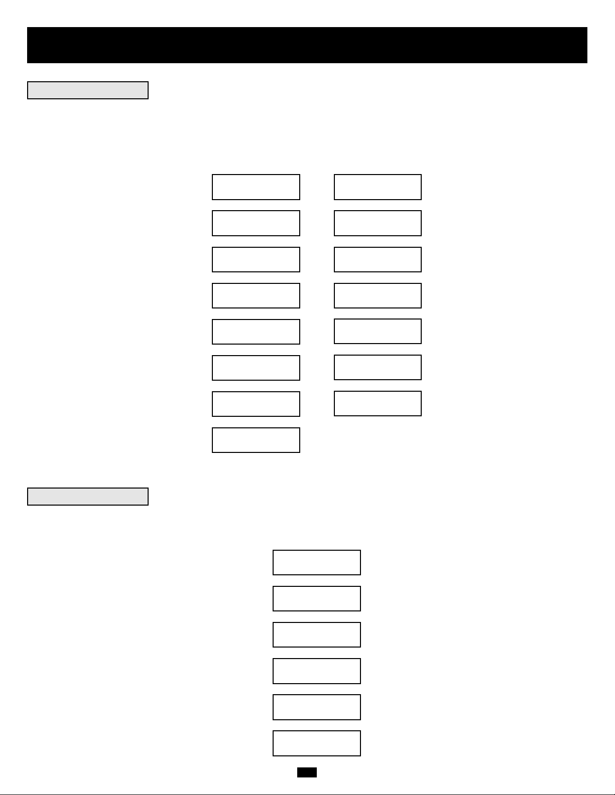
Important Safety Warnings
Mounting
Connection
Features
Operation
Storage and Service
Warranty and Warranty Registration
Español/Français
2
3
5
8
12
15
15
16/32
Optional Connection
9
Manual Bypass Operation
10
WARRANTY
REGISTRATION:
register online today for a
chance to win a FREE Tripp Lite
product—www.tripplite.com/warranty
Page 2

2
Important Safety Warnings
SAVE THESE INSTRUCTIONS. This manual contains important instructions and warnings that should be followed during the installation and
maintenance of all Tripp Lite SmartOnline Rackmount/Tower UPS Systems and their batteries.
UPS Location Warnings
• Install your UPS indoors, away from excess moisture or heat, direct sunlight, dust and conductive contaminants.
• Install your UPS in a structurally sound area. Your UPS is extremely heavy; take care when moving and lifting the unit.
• Only operate your UPS at indoor temperatures between 32° F and 104° F (between 0° C and 40° C). For best results, keep indoor
temperatures between 62° F and 84° F (between 17° C and 29° C).
• Leave adequate space around all sides of the UPS for proper ventilation.
• Do not install the UPS near magnetic storage media, as this may result in data corruption.
UPS Connection Warnings
• The power supply for this unit must be single-phase rated in accordance with the equipment nameplate. It also must be suitably grounded.
Equipment Connection Warnings
• Do not use Tripp Lite UPS Systems in life support applications in which a malfunction or failure of a Tripp Lite UPS System could
cause failure or significantly alter the performance of a life support device.
• Connect your UPS power module’s grounding terminal to a grounding electrode conductor.
• The UPS is connected to a DC energy source (battery). The output terminals may be live when the UPS is not connected to an AC supply.
Maintenance Warnings
• Your UPS power module and battery module(s) do not require routine maintenance. Do not open them for any reason. There are no
user-serviceable parts inside.
Battery Warnings
• Do not operate your UPS without connecting it to an external battery module.
• Connect only Tripp Lite battery modules to your UPS power module’s external battery connector.
• Batteries can present a risk of electrical shock and burn from high short-circuit current. Observe proper precautions. Unplug and turn
off the UPS and disconnect the battery module from the UPS before performing battery replacement. Use tools with insulated
handles. Battery replacement should only be performed by authorized service personnel using the same number and type of batteries
(Sealed Lead-Acid). Do not open the UPS or batteries; there are no user-serviceable parts inside. Do not short or bridge the battery
terminals with any object. CAUTION: Do not dispose of batteries in a fire, as this could cause them to explode. The batteries in your
battery module are recyclable; refer to local codes for disposal requirements. In the USA call 1-800-SAV-LEAD (1-800-728-5323),
1-800-8-BATTERY (1-800-822-8837), or visit www.rbrc.com for complete recycling information.
• Do not open or mutilate the batteries. Released electrolyte is harmful to the skin and eyes, and may be toxic.
• Fuses should be replaced only by factory authorized personnel. Blown fuses should be replaced only with fuses of the same number
and type.
• Service and repair should be done only by trained personnel. During any service work to the UPS, it should be turned off or manually
bypassed via the transformer. Note that potentially lethal voltages exist within this unit as long as the battery supply
is connected.
• Do not connect or disconnect battery module(s) while the UPS is operating from the battery supply or when the detachable PDU is
not in bypass mode.
• During “hot-swap” battery module replacement your UPS will be unable to provide battery backup in the event of a blackout.
Page 3
3
Mounting (Rack)
1
4-Post Mounting
1
2
3
A
B
C
F
E
G
4
H
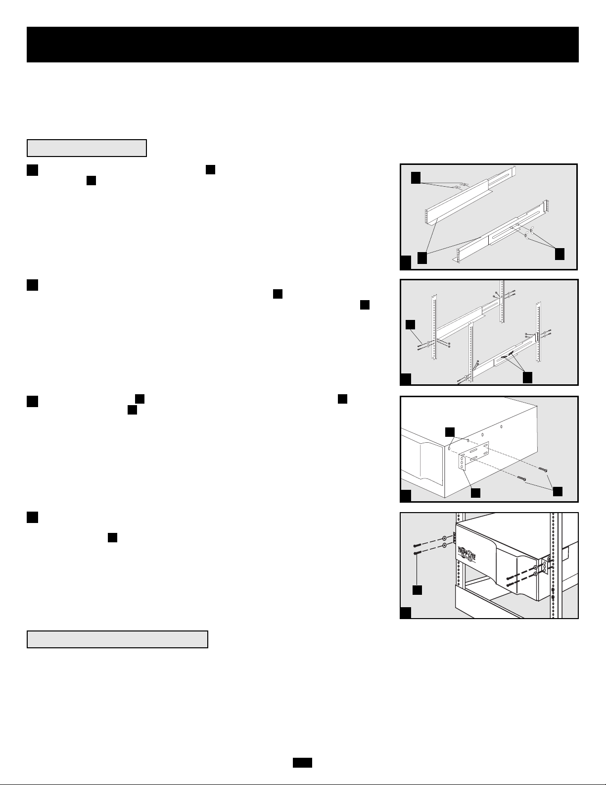
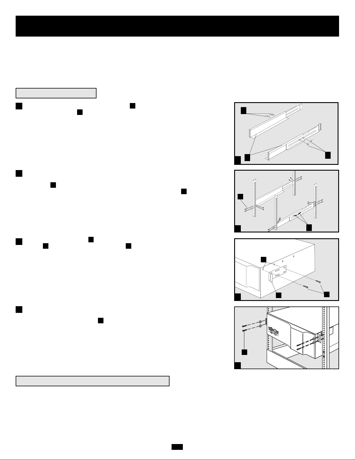
Connect the two segments of each shelf using the included attached screws and
wing nuts . Leave the screws slightly loose so that the shelves can be adjusted in
the next step.
Adjust each shelf to fit your rack, then mount them in the lowest available space
of your rack with the screws, nuts and washers provided . Note that the support
ledges should face inward. Tighten the wingnuts that connect the shelf segments .
Attach mounting ears to the front mounting holes of your equipment using
the screws provided . The ears should face forward.
Using an assistant, lift your equipment and slide it onto the mounting shelves.
Attach your equipment to the rack by passing the screws, nuts and washers
(user-provided) through its mounting ears and into the rack rails.
To mount your equipment in a 2-post rack, you must purchase a Tripp Lite 2-Post
Rackmount Installation Kit (model: 2POSTRMKIT, sold separately) for each module
installed. See the Installation Kit's owner's manual for complete mounting instructions.
H
G
FE
D
C
B
A
4
Mount your equipment in either a 4-post or 2-post rack or rack enclosure.The user must determine the fitness of hardware and procedures
before mounting. If hardware and procedures are not suitable for your application, contact the manufacturer of your rack or rack enclosure.
The procedures described in this manual are for common rack and rack enclosure types and may not be appropriate for all applications.
Note: The power module and battery module must be installed in separate shelves.
2
3
2-Post (Telecom) Mounting
B
D
Page 4
4
Mounting (Tower)
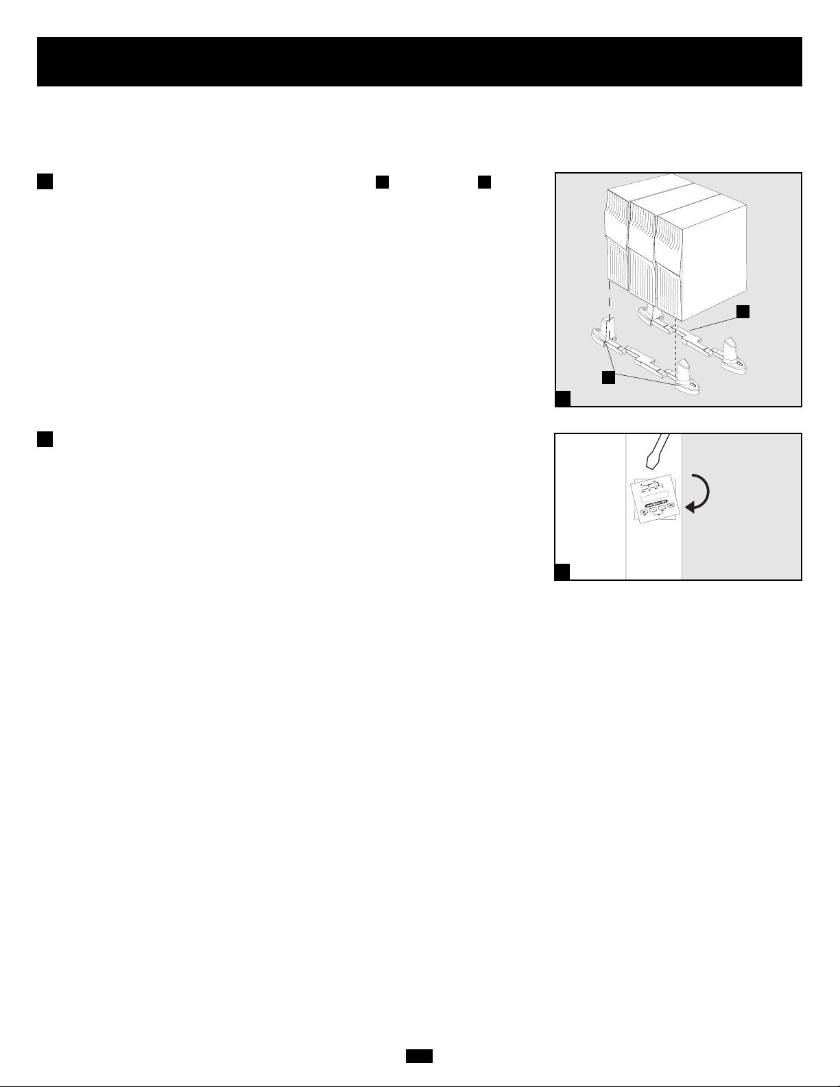
The UPS system is shipped with two sets of plastic feet and extensions that
can be used to tower mount the UPS’s power module, a battery module and a second
battery module (9U total).
Adjust the feet to a width of 10.25 inches (26 cm) for a UPS power module and
battery module, or to a width of 15.375 inches (39 cm) for three units. Align the feet
in your installation area, approximately 10 inches (26 cm) apart. Have one or more
assistants help you place the units on their sides in the feet. The control panel of
the UPS should be the UPS’s upper corner and face outward.
Rotate the power module’s Control Panel to view it easier while the UPS is tower
mounted. Insert a small screwdriver, or other tool, in the slots on either side of the
Control Panel. Pop the panel out; rotate it; and pop the panel back into place.
BA
1
1
A
B
Mount all modules in an upright, tower position using included base stands. The user must determine the fitness of hardware and procedures
before mounting.
2
2
Page 5
5
Features
Before installing and operating your UPS, familiarize yourself with the location and function of the features of each component.
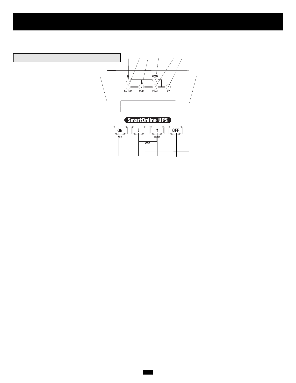
Power Module Front Panel Controls
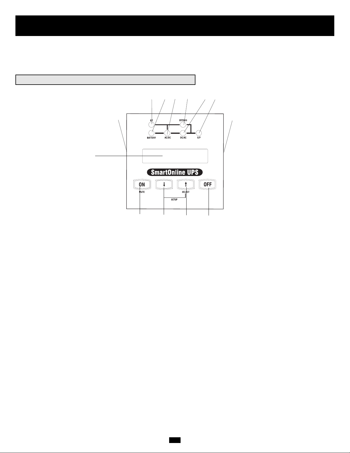
1. LCD DISPLAY: This backlit (16 × 2 character) dot matrix display indicates a wide range of UPS operating conditions and diagnostic
data. It also displays UPS settings and options when the UPS is in setup mode.
2. ON/MUTE BUTTON: Press this button and hold it until you hear a beep to turn the UPS system’s inverter ON. If the UPS’s battery
alarm is sounding, press this button to silence it.
3. SCROLL DOWN/EXIT SETUP BUTTON: This button allows you to browse through different options and power readings on the
LCD display. Momentarily pressing it causes the LCD screen to display a different power reading (see “Operation”, pg. 12). Pressing it
and the SCROLL UP Button together puts the UPS in setup mode, where this button is used to scroll through setup options and to exit
setup mode.
4. SCROLL UP/SELECT BUTTON: This button allows you to browse through different options and power readings on the LCD display. Momentarily pressing it causes the LCD screen to display a different power reading (see “Operation”, pg. 12). Pressing it and the
SCROLL DOWN Button together puts the UPS in setup mode, where this button is used to select setup options.
5. OFF BUTTON: Press this button until you hear a beep to turn the UPS system’s inverter OFF.
6. O/P (OUTPUT) LED: This green light will illuminate to indicate your UPS is supplying AC power to connected equipment.
7. DC/AC (INVERTER) LED: This green light will illuminate to indicate the UPS’s DC/AC inverter is activated.
8. BYPASS LED: This green light will illuminate when the UPS is providing filtered mains power without engaging its converter or
inverter. If this LED is lit, connected equipment will not receive battery power in the event of a blackout.
9. AC/DC (Converter) LED: This green light will illuminate to indicate the UPS’s AC/DC converter is charging the connected battery pack(s).
10. BATTERY LED: This red light will illuminate when the UPS is discharging the battery to provide connected equipment with AC
power. An alarm will sound which can be silenced by pressing the ON/MUTE Button. This LED will remain lit after the alarm is
silenced.
11. I/P (INPUT) LED: This green light will illuminate to indicate an AC input supply is present.
12. ACCESS SLOTS: To rotate the controls, insert a flathead screwdriver into these slots and gently lever the panel out. Taking care not
to excessively twist or yank the cables connecting the controls to the rest of the UPS, turn the controls to the desired orientation and
reinsert them.
1
2 345
6879
10
11
12
12
Page 6
6
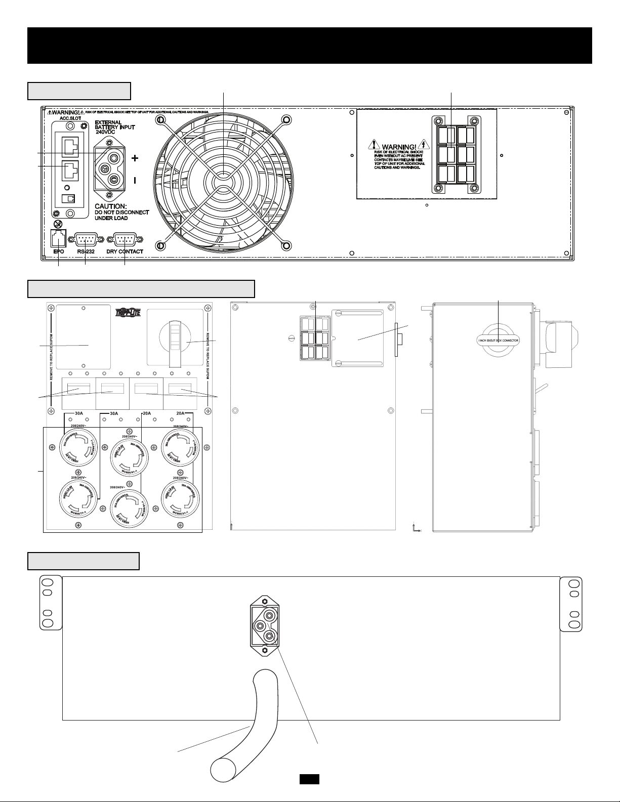
Features (Rear Panel)
see page 7 for feature descriptions
Power Module
1
3
4
5
6
7
Battery Module
15
16
Detachable Power Distribution Unit
2
11
9
9
8
10
12
13
14
Front Rear Left Side
Page 7

7
Features (Rear Panel)
continued
Power Module Feature Description
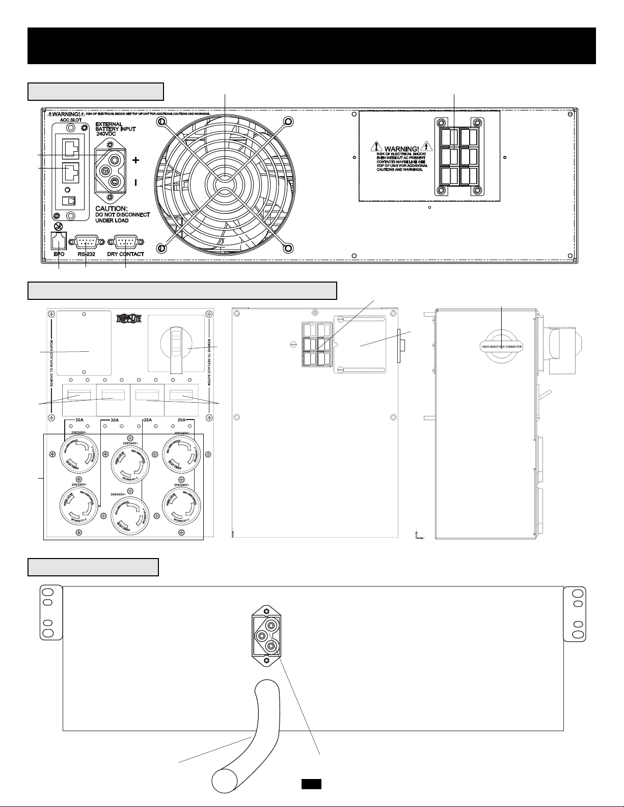
1. Input Terminal Block: Use these terminals to connect your power module to the detachable PDU.
2. External Battery Connector: Use this to connect one or more Tripp Lite battery modules to the power module. Remove the cover for
access. The power module will not start without a connection to a charged battery module. Refer to the battery module owner’s manual
for connection instructions and safety warnings.
3. Exhaust Fan: This cools and ventilates the inside of the power module.
4. Accessory Slot: Remove the small cover panel to install optional accessories to remotely control and monitor your UPS system. Visit
Tripp Lite on the Web (www.tripplite.com) to learn about available SNMP, network management and connectivity products that may be
installed in this slot.
5. EPO (Emergency Power Off) Port: Used to connect the power module to a contact closure switch to enable emergency power off. See
“Optional Connection” section for details.
6. RS-232 Communication Port: This female DB9 serial port may be used to connect your UPS to a workstation or server. It uses RS-232
protocol to communicate with a connected computer. It is used with Tripp Lite software and the included serial cable to monitor and
manage the UPS remotely over a network and to automatically save open files and shut down equipment during a blackout. See
“Optional Connection” for details.
7. Dry Contact Interface Port: This female DB9 port sends contact-closure signals to indicate line-fail and low-battery status. See
“Optional Connection” for details.
Detachable Power Distribution Unit Feature Description
8. AC Output Receptacles: Accept direct plug-in connection of NEMA L6-30P or NEMA L6-20P equipment plugs.
9. AC Output Breakers: Control output power to the PDU's AC output receptacles.
10.Maintenance Bypass Switch: Permits qualified service personnel to remove the PDU from the power module for routine maintenance
without disrupting power to the load. When this switch is set to BYPASS the load will receive unfiltered AC utility power and no
battery backup power will be available in the event of a blackout. See the “Manual Bypass Operation” section for detailed manual bypass
procedures.
WARNING! For qualified service personnel only. If the complete bypass procedure (see “Manual Bypass Operation,” p. 10) is
not followed, the UPS will not be adequately powered down, presenting a risk of death or serious injury from contact with high
voltage.
11.Utility Input Terminal Block: Use these terminals to connect the PDU to utility power. To access the terminals, unscrew and remove
the terminal block cover.
12.Power Module Input Terminal Box: Use these terminals to connect the PDU to the Power Module.
13.Sliding Cover for Power Module Input Terminals: Slide this cover over the terminals after detaching the PDU from the Power
Module during manual Bypass Operation (p. 10).
14. Input Terminal Block Cable Access: Located on the left side of the PDU.
Battery Module Feature Description
15. Input Connector: Use this connector to daisy chain additional battery modules onto the first. Remove the cover panel for access. Refer
to the battery module owner’s manual for connection instructions and safety warnings.
16. Output Cable: Use this cable to connect the battery module to the power module or to another battery module. The power module will
not start without a connection to a charged battery module. Refer to the battery module owner’s manual for connection instructions and
safety warnings.
Page 8
8
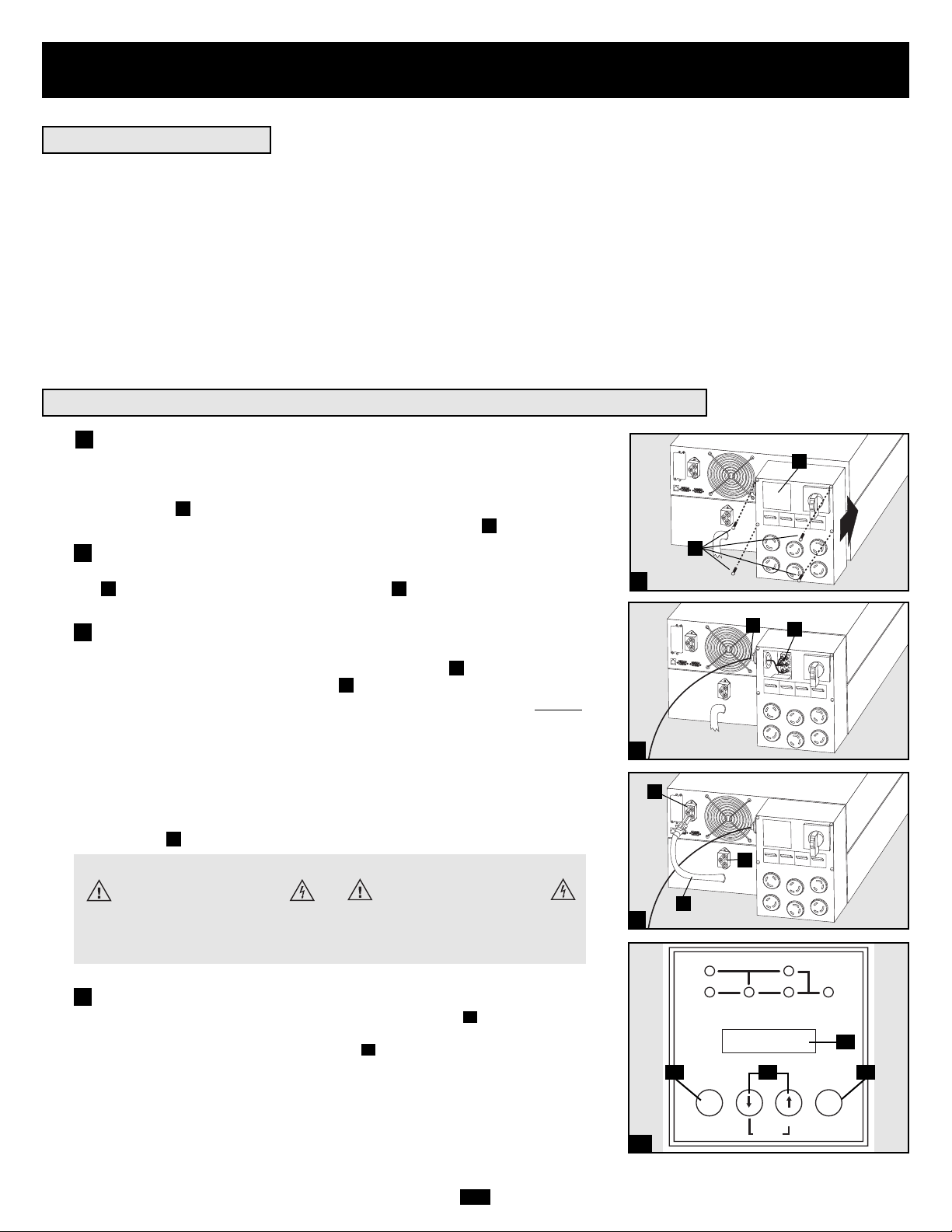
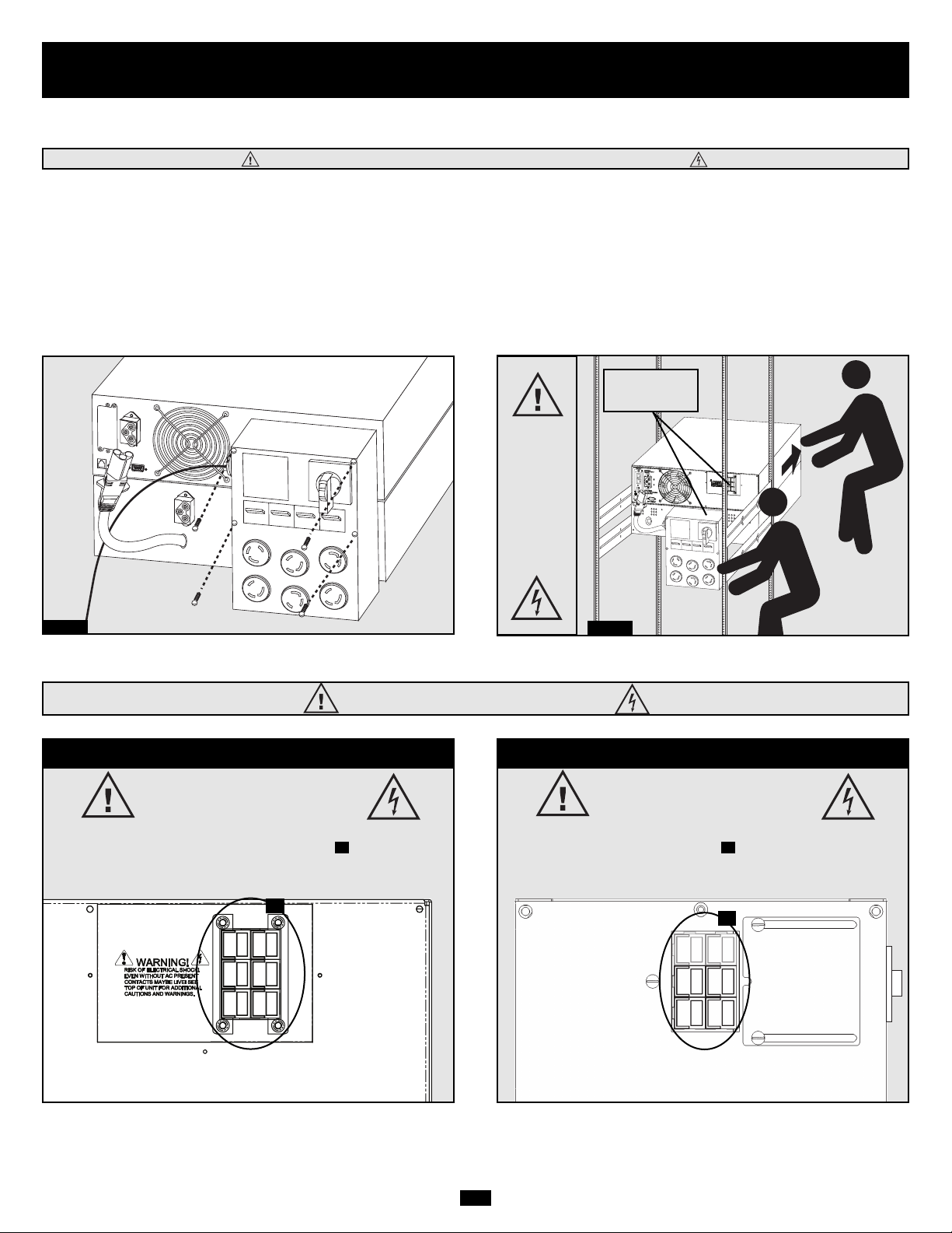
Attach the PDU to the Power Module and Battery
Module.
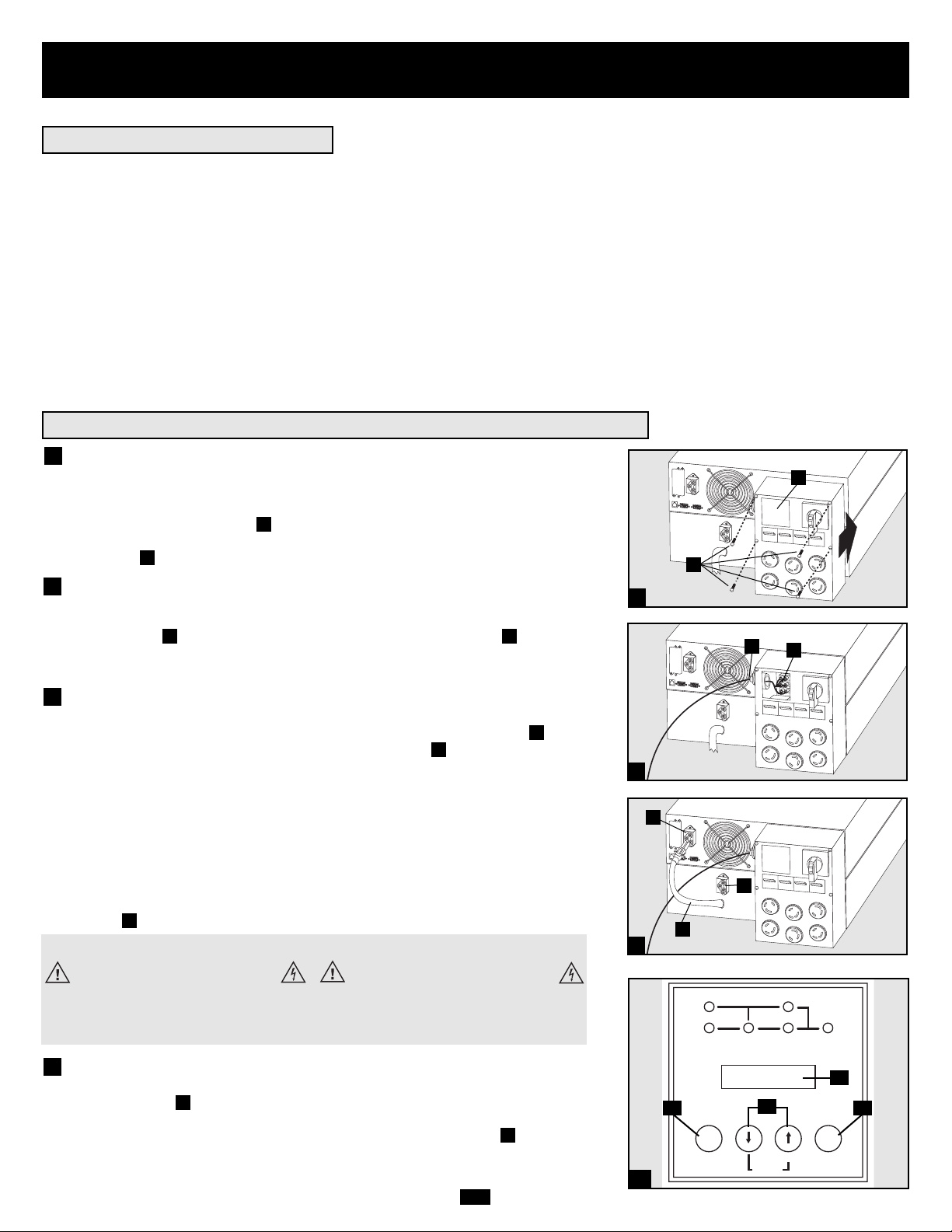
Align and connect the PDU's power module input terminals with the terminals
on the back of the Power Module. Secure the PDU to the Power Module with
four screws . Before proceeding further, ensure that the Bypass Switch is set
to NORMAL. Remove the utility input terminal block cover .
Hardwire the PDU to a Utility Power Source.
Pass a user-supplied cable through the knockout on the left side of the PDU
and connect it to the PDU's input terminals . Replace the terminal block
cover. Connect the other end of the cable to a utility power source.
Connect the battery module to the power module.
Consult the owner’s manual that came with your battery module. Fully insert
the connector on the end of the battery module’s cable into the connector
on the rear panel of the power module . Small sparks may occur; this is normal. NOTE: the power module does not contain internal batteries and will not
start until a battery module is connected. The battery modules are fully charged
prior to shipping. However, before expecting full backup capability (particularly
if the battery module has been stored for an extended period) after the UPS system
is connected to a utility power source, allow the battery module to recharge for
12 hours. Once the UPS system is in use, it will charge the batteries and maintain
the charge level automatically. If needed, connect additional battery modules
in a daisy-chain with each module’s cable inserted into the previous module’s
connector .
G
F
E
DC
B
A
1
2
2
Connection
• Wiring must be done by a qualified electrician.
• When making wiring connections, observe the cable connection regulations appropriate to your area [e.g. National Electrical Code (NEC)
in the U.S.] at all times. Be sure to install an easily accessible disconnect switch in your installation wiring so you may cut off the UPS’s
AC input during fires and other emergencies. Ensure that cables are fitted with cable sleeves and are secured by connector clamps.
Tighten connections with a torque of not less than 24-28 inch-pounds (2.7-3.2 NM).
• Make sure that your equipment is properly grounded.
• Using cables of improper size may damage your equipment and cause fire hazards. Choose appropriate cabling and protection circuits to
make wiring connections. Ground conductors must be the same size and type as the power conductors used.
• See the product case for input and output ratings and refer to National Electrical Code (NEC) guidelines for proper wire gauge and
output protection circuit requirements.
Connecting Modules to Each Other and to Utility Power and Equipment
Hardwiring Cautions
3
A
1
D
3
B
C
E
F
G
Contacts on Power/Battery Module
WARNING! High Voltage!
Risk of electrical shock!
Due to the presence of high voltage internal
batteries, even without AC present, these
contacts are live!
Do not let these contacts touch any surface!
Contacts on Detachable PDU
WARNING! High voltage!
Risk of electrical shock!
If AC is present and Bypass Switch is set to
"Bypass", these contacts are live!
Do not let these contacts touch any surface!
I
H
K
J
4a
Power ON
Turn UPS inverter ON: Press the UPS's “ON” Button until you hear a
beep to begin inverter operation. Your UPS will perform a brief self-test and
show the results on the LCD Display . See “Startup Self-Test” in the
“Operation” section for the display sequence.
H
I
4
I/P BYPASS
BATTERY AC/DC DC/AC O/P
MUTE SELECT
SETUP
OFFON
Page 9
9
Cold Start (optional): To use your UPS as a stand-alone power source when
AC input power is unavailable (i.e. during a blackout), you can “cold start”
your UPS and power connected equipment from the UPS's battery. Your UPS's
battery must be at least partially charged for this operation to succeed. Press
and hold the “ON” Button until you hear a beep to cold start your UPS. The
LCD Display will show ON BATTERY MODE. Battery power will begin
discharging. Some electronic equipment may draw more amps during startup;
when cold starting, consider reducing the initial load on the UPS.
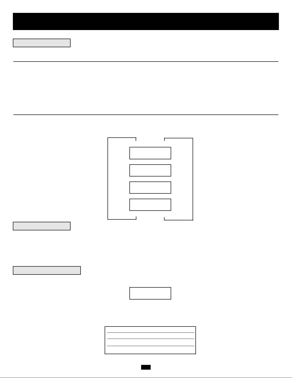
Configure UPS output: Put the UPS into bypass mode by holding the OFF
button down until the UPS beeps, then put the UPS into setup mode by
holding down both of its scroll buttons at once. Scroll through the setup
options and select the appropriate setting for each of the following options.
Output Voltage: Select 200, 208, 220, 230 or 240V AC.
Output Frequency: The UPS will automatically select 50 or 60 Hz to match
the input.
Economy Mode: The UPS can provide true on-line operation with zero trans-
fer time. It can also operate in a more energy-efficient line-interactive mode.
Select “Economy On” to put the UPS in line-interactive mode. Select
“Economy Off” to put the UPS in on-line mode. After setting these options,
exit the setup mode with the scroll buttons , then exit bypass mode by holding the ON button down until the UPS beeps.
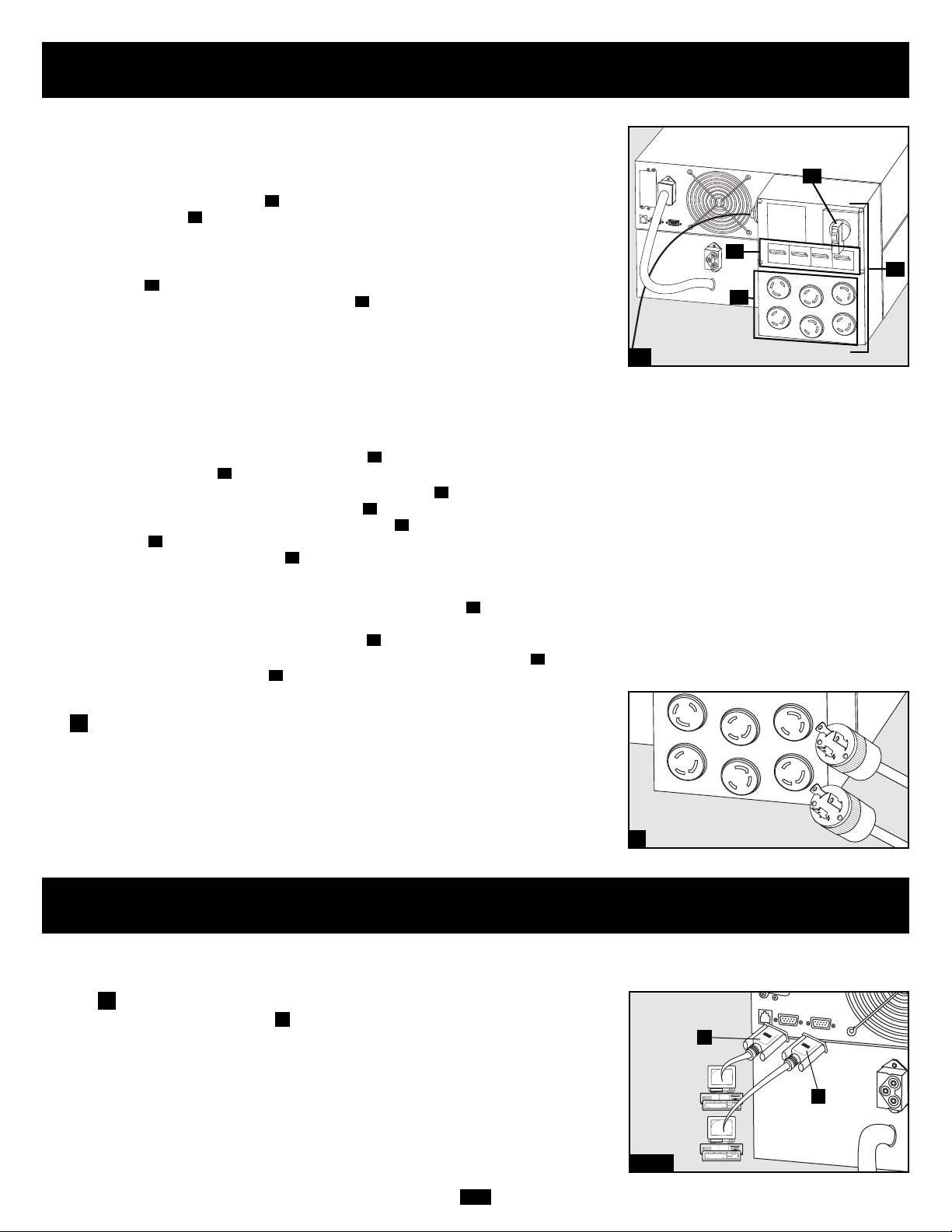
Turn UPS output power ON: Press the ON button until the UPS beeps.
Turn the UPS Output Circuit Breakers ON. (The UPS Output Circuit
Breakers are located on the detachable PDU .) Turn the Manual Bypass
Switch from BYPASS to NORMAL. The UPS will now provide output
power through its AC outlets to connected equipment.
N
L
O
M
I
I
J
J
K
H
I
Power OFF (optional)
Turn UPS inverter OFF: Press the UPS's “OFF” Button until you hear a
beep. Your load will still be energized. The inverter is now off, but your UPS
is not fully deactivated. The LCD Display will show BYPASS MODE
Turn UPS output power OFF: Turn off the Output Circuit Breakers locat-
ed on the detachable PDU . Your load will no longer be energized, and the
LCD Display will be dark.
O
M
H
K
M
O
N
L
Connection
continued
Plug Your Equipment into the PDU's Outlets.
Your UPS is designed to support electronic equipment only. You will overload
your UPS if the total VA rating for all the equipment you connect exceeds the
UPS's output capacity. Do not connect household appliances or laser printers
to the UPS's outlets. To find your equipment's VA ratings, look on their nameplates. If the equipment is listed in amps, multiply the number of amps by the
input voltage (240V, 208V or 120V) to determine VA. (Example: 1 amp × 120 =
120 VA).
5
5
4b
Optional Connection
The following connections are optional. Your UPS system will function properly
without these connections.
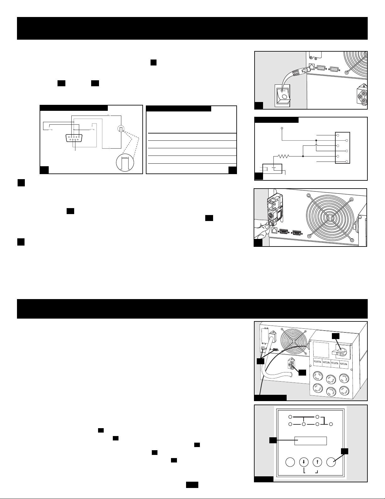
RS-232 Serial Communication Connection
Use the included cable to connect the power module's RS-232 port to
the communication port on your computer. This will allow full network
monitoring and control of your UPS system. Install on your computer the
Tripp Lite PowerAlert Software appropriate to your computer's operating
system.
Note: RS-232 serial communications are unavailable for PowerAlert Software
monitoring while the SNMP/WEB Card is installed in the UPS system's accessory slot.
Removing the SNMP/WEB Card from the accessory slot will restore the availability of
RS-232 serial communications for PowerAlert Software monitoring.
A
1
1a/1b
A
B
Page 10
10
Manual Bypass Operation
(for power module maintenance or replacement)
The UPS system includes a self-contained power/battery module along with an independent, detachable PDU with a bypass switch. This switch allows qualified service personnel
to remove the detachable PDU from the power/battery module for routine maintenance
without disrupting power to connected loads. While this switch is set to “BYPASS”, connected equipment will receive unfiltered AC utility power, but the equipment will not
receive battery power in the event of a blackout.
Note: If desired, an optional hardwire detachable PDU is also available separately from
Tripp Lite. Contact Tripp Lite for details.
WARNING! For qualified service personnel only. Failure to follow the bypass procedure completely will not adequately power down the UPS power/battery module,
resulting in the continued risk of death or injury from potential contact with high
voltage. The UPS's power/battery module and detachable PDU are extremely heavy.
This procedure requires several people to perform.
Step 2
D
C
UPS Power/Battery Module Removal
STEP 1. Disable PowerAlert Software and disconnect communication cables from the
communication ports on the UPS power/battery module.
STEP 2. Press UPS's “OFF” Button , if the UPS is powered, until you hear a beep and
see a “BYPASS MODE” message shown in the LCD Display .
STEP 3. Turn the detachable PDU's Bypass Switch to “BYPASS”.
STEP 4. If an external battery module is connected to the UPS , disconnect it from the UPS.
The UPS power/battery module is now safely powered down and it can be detached
from the PDU to perform maintenance/replacement.
E
B
D
C
A
Steps 1, 3 & 4
E
A
B
Contact-Closure Communication Connection
Use a user-supplied contact-closure DB9 cable to connect the power module's
Dry-Contact port to the communication port on your computer or other equipment.
This will allow basic contact-closure signals to be sent to and from the UPS. Refer
to diagram and table to determine the signals carried by this port. Install on
your computer the Tripp Lite PowerAlert Software appropriate to your computer's
operating system.
EPO Port Connection
This optional feature is only for those applications which require connection to a
facility’s Emergency Power Off (EPO) circuit. When the power module is connected to this circuit, it enables emergency shutdown of the output. Using the
included cable , connect the power module’s EPO port to a user-supplied remote
switch. The pin assignments for the EPO port are shown in diagram . Note: if
there is a short between pins 2 and 3, 2 and 5, 4 and 5, or 3 and 4, the UPS system
will power off.
Internal SNMP/WEB Card Insertion
Remove the small cover panel from the accessory slot to use optional accessories
to remotely monitor and control your UPS. Contact Tripp Lite Customer Support
at (773) 869-1234 for more information, including a list of available SNMP, network management and connectivity products.
2b
2a
1d1c
B
EPO PIN ASSIGNMENT
2
2a
2b
3
3
DRY CONTACT INTERFACE DIAGRAM
UPS
Operating
Mode Pin 8,3 Pin 1,3 Pin 6,3
Normal OPEN OPEN *
Back Up CLOSE * *
Low Battery CLOSE CLOSE *
Fault * * CLOSE
* Inactive: may be in either state
DRY CONTACT INTERFACE TABLE
1c
1d
Optional Connection
continued
Note: RS-232 serial communications are unavailable for PowerAlert Software monitoring while the SNMP/WEB Card is installed in the UPS system's accessory
slot. Removing the SNMP/WEB Card from the accessory slot will restore the availability of RS-232 serial communications for PowerAlert Software monitoring.
LOW BATTERY
NO
COM NC
MAXIMUM CAPACITY OF DRY CONTACT: AC250V/3A • DC30V/3A
54321
9
8
7
SIGNAL FROM COMPUTER
BACK-UP
6
COM NC
lm in. > 3.3 mA
REMOTE SHUTDOWN SIGNAL
NO
FROM EXTERNAL
>2 sec
12 V
0
12V
1K
1
X
2
3
4
5
6
X
I/P BYPASS
BATTERY AC/DC DC/AC O/P
MUTE SELECT
SETUP
OFFON
Page 11
11
Manual Bypass Operation
(for power module maintenance or replacement)
STEP 5: Remove the four screws that hold the detachable PDU to the power/battery module.
STEP 6: Using several assistants at each end, carefully pull the detachable PDU away from the power/battery module. During this process,
ensure that each section is properly supported after they are separated. If the sections are detached in a rackmount application,
ensure that each section remains adequately supported by the UPS's rackmount rails. Remove the rackmounting hardware from
the front panel of the UPS; slide the power and battery modules forward, and remove. If it is desired to leave the detached PDU
in the rack, a user-supplied crosspiece or shelf must be installed in the rear of the rack.
If the sections are detached in a tower application, ensure that the PDU is supported by the UPS's tower feet. Adjust the tower
feet so they are as close together as possible.
To reattach the PDU, reverse the process listed above.
WARNING! High Voltage! Risk of electrical shock! SEE BELOW.
Step 5
Step 6
WARNING!
High
Voltage!
Risk of
electrical
shock!
SEE
BELOW.
See Warning
Statements
below!
High Voltage Warnings
Contacts on Power/Battery Module
WARNING! High Voltage!
Risk of electrical shock!
Due to the presence of high voltage internal batteries, even
without AC present, these contacts are live!
Do not let these contacts touch any surface!
A
Contacts on Detachable PDU
WARNING! High voltage!
Risk of electrical shock!
If AC is present and Bypass Switch is set to “Bypass”,
these contacts are live!
Do not let these contacts touch any surface!
B
A
B
Page 12
12
DIAGNOSTIC MODE
AC/DC OK
DIAGNOSTIC MODE
TESTING INVERTER
ON BATTERY MODE
LOAD = XXX% X.XXKW
Operation
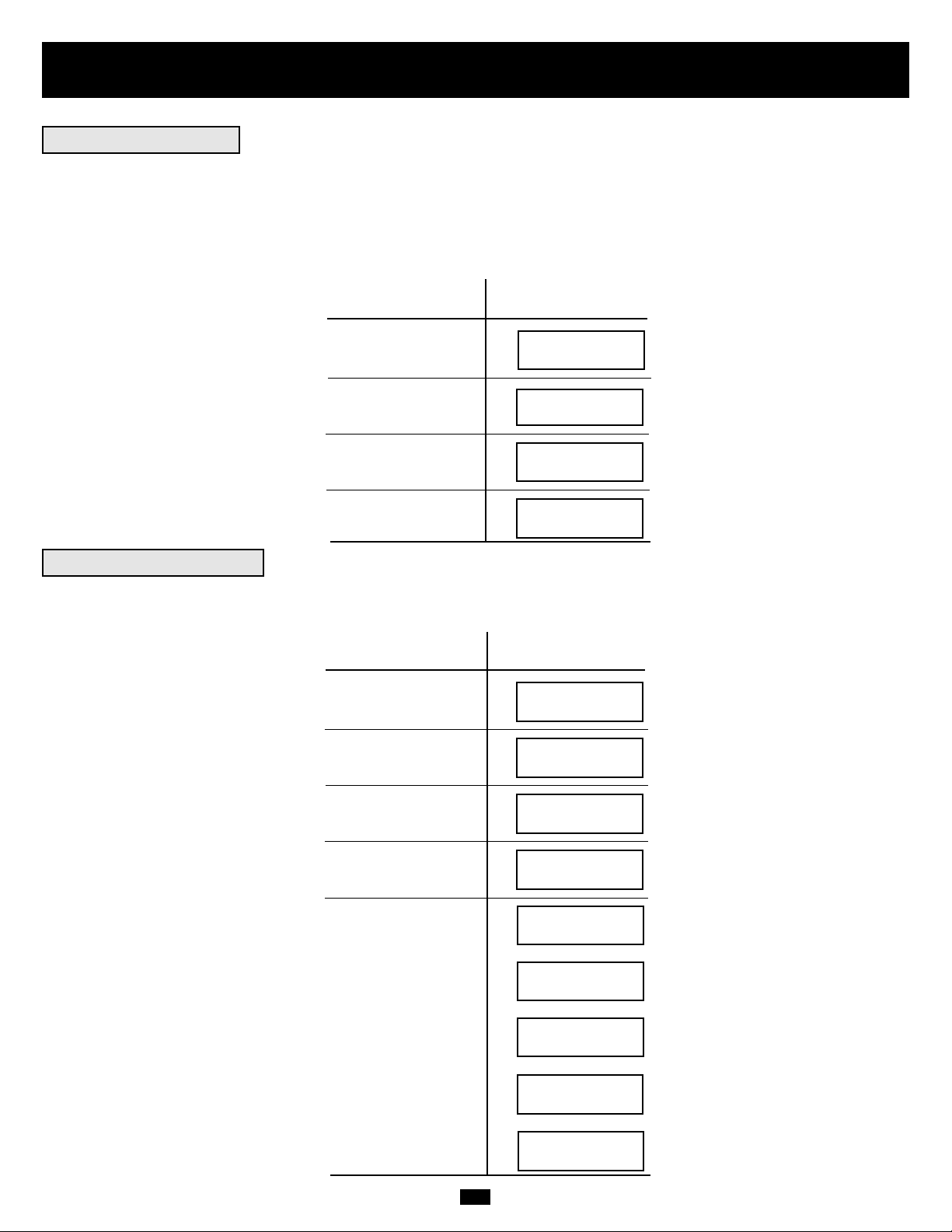
When you turn the UPS ON, it will enter Diagnostic Mode and perform a brief self-test lasting about 15 seconds. The results of the self-test
are shown on the LCD screen in the sequence below.
DIAGNOSTIC MODE
FREQ OUT = XXHz
DIAGNOSTIC MODE
INPUT AC OK
DIAGNOSTIC MODE
INPUT AC OK
DIAGNOSTIC MODE
BATTERY OK
DIAGNOSTIC MODE
CHARGER OK
DIAGNOSTIC MODE
AC/DC OK
DIAGNOSTIC MODE
TESTING INVERTER
ONLINE MODE
LOAD = XXX% X.XXKW
DIAGNOSTIC MODE
FREQ OUT = XXHz
DIAGNOSTIC MODE
INPUT AC BAD
DIAGNOSTIC MODE
INPUT AC BAD
DIAGNOSTIC MODE
BATTERY OK
M
M
M
M
M
M
M
M
M
M
M
M
M
STARTED WITH
AC INPUT
COLD
START*
*Note: If the UPS is cold started, its BATTERY LED will be lit.
If a problem is detected during the self-test, the LCD will display a error message. If your UPS displays any of the following messages in
its LCD, call Tripp Lite Technical Support at (773) 869-1234 for service.
BAD BATTERY!
CALL FOR SERVICE
CHARGER FAILURE!
CALL FOR SERVICE
AC/DC FAILURE!
CALL FOR SERVICE
INVERTER FAILURE!
CALL FOR SERVICE
OUTPUT FAILURE!
CALL FOR SERVICE
FAN FAILURE!
CALL FOR SERVICE
Startup Self-Test
Failed Self-Test
Page 13
13
Operation
continued
During normal operation, the first line of your LCD Display shows which operating mode your UPS is in: Online, Economy, On Battery,
or Bypass.
Online mode: The UPS provides AC power while utility power is available and switches to On Battery mode instantly (zero transfer time)
if AC power is interrupted.
Economy mode: The UPS provides AC power at high efficiency while utility power is available and switches to On Battery mode quickly
if AC power is interrupted.
On Battery mode: The UPS provides AC power from battery backup so long as battery power lasts. It switches back to Online or Economy
mode if utility power is available and shuts down if it runs out of battery power.
Bypass mode: The UPS provides AC power while utility power is available. The UPS shuts down if AC power is interrupted.
The second line of the LCD Display shows basic power conditions. Push the SCROLL buttons to browse through these basic power conditions
in the sequence shown below.
XXXX MODE
LOAD = XXX% X.XXKW
XXXX MODE
IN = XXXV XX.X Hz
XXXX MODE
OUT = XXXV XX.X Hz
XXXX MODE
BATTERY = XXXVDC
M
M
M
When in the On Battery mode, the UPS power module will beep to inform you that it is using battery power to support connected equipment.
If its connected batteries are at more than half capacity, it will beep every two seconds. If its connected batteries are below half capacity, it
will beep twice a second. If its connected batteries are nearly depleted, the UPS power module will beep continuously.
To silence the On Battery Alarm, press the “ON/MUTE” button.
When the UPS detects an output overload, its LCD will switch to the following display:
The UPS will then begin a countdown. If the UPS is still overloaded at the end of the countdown, the UPS will automatically go to Bypass
Mode to protect its inverter. The duration of the countdown varies with the severity of the overload, as follows:
OVERLOAD!
LOAD = XXX% X.XXKW
Overload Condition Countdown Duration
102% - 125% 1 minute
125% - 150% 30 seconds
>150% Immediate
M
M
L
L
L
Normal Operation
On Battery Alarm
Overload Messages
Page 14
14
Operation
continued
While in Bypass Mode, the UPS monitors its input voltage and passes that input power along to connected equipment. The UPS will not
provide battery backup in Bypass Mode.
If the output voltage deviates from an acceptable range (between 15% higher and 20% lower than nominal), the UPS displays the condition
on its LCD and stops supplying output power to its load. If power levels return to an acceptable level, the UPS resumes supplying power
to the load, and its LCD reports that output voltage was too high or too low at one time, but has returned to nominal.
>15% Higher
Than Nominal
>20% Lower
Than Nominal
Was Too High,
Now Nominal
Was Too Low,
Now Nominal
BYPASS VOLTAGE
CONDITIONS
LCD DISPLAY
MESSAGES
Your UPS will shut down and the LCD will display a message if it detects one of the following conditions. Note: During all these conditions,
the “Input,” “Output” and “Bypass” LEDs will be illuminated.
Extended
Overload
Output Short
Circuit
Remote Shutdown
Command (Via DB9)
Remote Shutdown
Command (Via EPO)
SHUTDOWN
CONDITIONS
LCD DISPLAY
MESSAGES
Internal
Faults
NO OUTPUT
BYPASS AC TOO HI
NO OUTPUT
BYPASS AC TOO LO
BYPASS MODE
BYPASS AC WAS HI
BYPASS MODE
BYPASS AC WAS LO
SHUT DOWN
OVERLOAD XXX%
SHUT DOWN
O/P SHORT CIRCUIT
SHUT DOWN
REMOTE COMMAND
SHUT DOWN
EMERGENCY STOP!
SHUT DOWN
+ DC BUS HIGH
SHUT DOWN
+ DC BUS LOW
SHUT DOWN
- DC BUS HIGH
SHUT DOWN
- DC BUS LOW
SHUT DOWN
OVERTEMPERATURE
Bypass Messages
Shutdown Messages
Page 15

15
Storage and Service
Before storing your UPS, turn it completely OFF. If you store your UPS for an extended period of time, recharge the UPS batteries for 4 to
6 hours once every three months. Note: after you connect the UPS to utility power, it will automatically begin charging its batteries. If you
leave your UPS batteries discharged for an extended period of time, they will suffer a permanent loss of capacity.
Your SmartOnline UPS is covered by the 2-year limited warranty period described below. A variety of Extended Warranty and On-Site
Service Programs are also available from Tripp Lite. For more information on service, call Tripp Lite Customer Support at (773) 869-1234.
Before returning your UPS for service, follow these steps:
1. Review the installation and operation instructions in this manual to ensure that the service problem does not originate from a misreading
of the instructions.
2. If the problem continues, do not contact or return the UPS to the dealer. Instead, call Tripp Lite at (773) 869-1233. A service technician
will ask for the UPS model number, serial number and purchase date and will attempt to correct the problem over the phone.
3. If the problem requires service, the technician will issue you a Returned Material Authorization (RMA) number, which is required for
service. They will also discuss proper packaging and shipping procedures. Any damages (direct, indirect, special, incidental or consequential) to the UPS incurred during shipment to Tripp Lite or an authorized Tripp Lite service center is not covered under warranty. UPS
Systems shipped to Tripp Lite or an authorized Tripp Lite service center must have transportation charges prepaid. Mark the RMA number
on the outside of the package. If the UPS System is within the 2-year warranty period, enclose a copy of your sales receipt. Return the UPS
for service using an insured carrier to the address given to you by the Tripp Lite service technician.
TRIPP LITE warrants its products including batteries to be free from defects in materials and workmanship for a period of two years from the date of initial purchase. After 90 days
from the date of purchase, TRIPP LITE’s obligation under this warranty is limited to replacing parts on such defective products.To obtain service under this warranty, you must call
TRIPP LITE or an authorized TRIPP LITE service center. Products must be returned to TRIPP LITE or an authorized TRIPP LITE service center with transportation charges prepaid
and must be accompanied by a brief description of the problem encountered and proof of date and place of purchase. This warranty does not apply to equipment which has been
damaged by accident, negligence or misapplication or has been altered or modified in any way. This warranty applies only to the original purchaser who must have properly registered the
product within 10 days of purchase.
The warranties of all TRIPP LITE surge suppressors are null and void if they have been connected to the output of any UPS system.The warranties of all TRIPP LITE UPS Systems
are null and void if a surge suppressor has been connected to its output receptacles.
EXCEPT AS PROVIDED HEREIN, TRIPP LITE MAKES NO WARRANTIES, EXPRESS OR IMPLIED, INCLUDING WARRANTIES OF MERCHANTABILITY AND FITNESS FOR A
PARTICULAR PURPOSE. Some states do not permit limitation or exclusion of implied warranties; therefore, the aforesaid limitation(s) or exclusion(s) may not apply to the purchaser.
EXCEPT AS PROVIDED ABOVE, IN NO EVENT WILL TRIPP LITE BE LIABLE FOR DIRECT, INDIRECT, SPECIAL, INCIDENTAL OR CONSEQUENTIAL DAMAGES ARISING
OUT OF THE USE OF THIS PRODUCT, EVEN IF ADVISED OF THE POSSIBILITY OF SUCH DAMAGE. Specifically, TRIPP LITE is not liable for any costs, such as lost profits or
revenue, loss of equipment, loss of use of equipment, loss of software, loss of data, costs of substitutes, claims by third parties, or otherwise.
The policy of TRIPP LITE is one of continuous improvement. Specifications are subject to change without notice.
WARRANTY REGISTRATION
Visit www.tripplite.com/warranty today to register the warranty for your new Tripp Lite product. You'll be automatically entered into a drawing for a chance to win a FREE Tripp Lite
product!*
* No purchase necessary.Void where prohibited. Some restrictions apply. See website for details.
FCC Radio/TV Interference Notice:
Note: This equipment has been tested and found to comply with the limits for a Class A digital device, pursuant to Part 15 of the FCC Rules. These limits are designed to provide
reasonable protection against harmful interference when operated in a commercial environment.This equipment generates, uses and can radiate radio frequency energy, and if not
installed and used in accordance with the instruction manual, may cause interference to radio communications.Operation of this equipment is likely to cause harmful interference in
which case users will be required to correct the interference at their own expense.The user must use shielded cables and connectors with this product. Any changes or modifications to this product not expressly approved by the party responsible for compliance could void the user's authority to operate the equipment.
Regulatory Compliance Identification Numbers
For the purpose of regulatory compliance certifications and identification, your Tripp Lite product has been assigned a unique series number.The series number can be found on the
product nameplate label, along with all required approval markings and information. When requesting compliance information for this product, always refer to the series number.The
series number should not be confused with the marking name or model number of the product.
Storage
2-Year Limited Warranty
Service
Warranty and Warranty Registration
Page 16

Manual del propietario
1111 W. 35th Street • Chicago, IL 60609 USA
Soporte al cliente: (773) 869-1234 • Servicios de aplicaciones: (773) 869-1236 • www.tripplite.com
Copyright © 2006 Tripp Lite. Todos los derechos reservados. SmartOnline es una marca registrada de Tripp Lite.
SmartOnline
™
monofásico de 7.5 kVA y 10 kVA
Sistemas UPS inteligentes realmente en línea
(Montaje en bastidor/torre)
• Incluye módulo de potencia, módulo de batería externa y PDU (unidad de datos de protocolo)
• La PDU desmontable cuenta con salidas e interruptor de derivación para mantenimiento*
• Apto para montar sobre rack y torre
* Se encuentra disponible una PDU opcional con conexión física desmontable; comuníquese con Tripp Lite para más detalles.
No conveniente para los usos móviles.
Advertencias de seguridad importantes
Montaje
Conexión
Características
Operación
Almacenamiento y servicio
Garantía
English/Français
17
18
20
23
27
30
31
1/32
Conexión opcional
24
Operación de derivación manual
25
Page 17

17
Advertencias de seguridad importantes
GUARDE ESTAS INSTRUCCIONES. Este manual contiene importantes instrucciones y advertencias que debe seguir durante la instalación y
el mantenimiento de todos los sistemas UPS SmartOnline de Tripp Lite de montaje en torre o bastidor, y sus baterías.
Advertencias sobre la ubicación del UPS
• Instale su UPS bajo techo, lejos de la humedad, el calor, el polvo, la luz solar directa y los contaminantes conductores.
• Instale su UPS en un área estructuralmente sólida. Su UPS es muy pesado; tenga cuidado al mover y levantar la unidad.
• Sólo opere su UPS a temperaturas bajo techo entre 32° F y 104° F (entre 0° C y 40° C) Para obtener mejores resultados, mantenga
las temperaturas bajo techo entre 62° F y 84° F (entre 17° C y 29° C).
• Deje una cantidad adecuada de espacio alrededor de todos los lados del UPS para una adecuada ventilación.
• No instale el UPS cerca de medios de almacenamiento magnético ya que puede dañar los datos.
Advertencias sobre la conexión del UPS
• El suministro de alimentación eléctrica para esta unidad debe ser monofásico y debe estar de acuerdo con la placa del equipo.
También debe estar puesta a tierra apropiadamente.
Advertencias sobre la conexión de equipos
• No utilice un UPS de Tripp Lite para aplicaciones de soporte de vida en las que un funcionamiento defectuoso o una falla del UPS
pudiera causar la falla o una alteración importante en el funcionamiento de algún dispositivo de soporte de vida.
• Conecte el terminal de tierra del módulo de potencia y/o del módulo del transformador de aislamiento de su UPS a un conductor del
electrodo de tierra.
• El UPS está conectado a una fuente de energía de corriente continua (batería). Los terminales de salida pueden estar con energía
cuando el UPS no está conectado a un suministro de corriente alterna.
Advertencias de mantenimiento
• Los módulos de potencia, del transformador de aislamiento y de la batería de su UPS no requieren ningún mantenimiento de rutina.
No los abra por ninguna razón. No hay partes en su interior que requieran mantenimiento por parte del usuario.
Advertencias sobre la batería
• No opere su UPS sin conectarlo a un módulo de batería externa.
• Sólo conecte módulos de baterías Tripp Lite al conector de baterías externas del módulo de potencia de su UPS.
• Las baterías pueden presentar riesgo de descarga eléctrica y quemadura debido a corto circuito. Tome las precauciones correspondientes. No deseche las baterías en el fuego. No abra la UPS ni las baterías. No acorte ni conecte los terminales para batería con ningún
objeto. Desconecte y apague la UPS antes de cambiar las baterías. Utilice herramientas con mangos aislados. Dentro de la UPS no
hay piezas que puedan ser reparadas por el usuario. El cambio de batería sólo debe realizarlo personal técnico autorizado y con el
mismo número y tipo de baterías (de plomo sellada). Las baterías son reciclables. Consulte los códigos locales sobre los requisitos
para desechar baterías, en los EE.UU. puede comunicarse con el 1-800-SAV-LEAD ó 1-800-8-BATTERY (1-800-822-8837) o bien
puede visitar www.rbrc.com para obtener información sobre reciclado.
• No abra las baterías ni les practique cortes. El electrolito liberado es nocivo para la piel y los ojos, y puede ser tóxico.
• Los fusibles deben ser reemplazados sólo por personal autorizado por la fábrica. Los fusibles quemados sólo deben reemplazarse con
fusibles del mismo número y tipo.
• El servicio y la reparación sólo deben llevarse a cabo por personal entrenado. Durante cualquier trabajo de servicio al UPS, este debe
apagarse o derivarse (bypass) en forma manual mediante el transformador. Observe que existen voltajes potencialmente fatales dentro
de esta unidad mientras está conectada la alimentación a la batería.
• No conecte ni desconecte los módulos de batería mientras el UPS esté operando con la alimentación de batería o cuando el módulo
de transformador no esté en modo Bypass (si su UPS incluye un módulo de transformador).
• Durante un reemplazo de su banco de baterías en operación (hot-swap), su UPS no podrá proporcionar respaldo de baterías en caso
de una falla del servicio eléctrico.
Page 18
18
Montaje (Bastidor)
1
Montaje de 4 postes
1
2
3
A
B
C
F
E
G
4
H
Conecte los dos segmentos de cada anaquel usando los tornillos incluidos y las
tuercas de mariposa . Deje los tornillos ligeramente flojos de modo que los
anaqueles puedan ajustarse en el siguiente paso.
Ajuste cada anaquel para que se acomode a su bastidor y luego instálelo en el espacio
más bajo disponible del bastidor con los tornillos, las tuercas y las arandelas suministradas . Note que los bordes de apoyo deben mirar hacia adentro. Apriete las
tuercas de mariposa que conectan los segmentos de los anaqueles .
Fije las orejas de montaje a los agujeros de montaje de la parte delantera de su
equipo usando los tornillos suministrados . Las orejas deben mirar hacia adelante.
Con la ayuda de otra persona levante su equipo y deslícelo en los anaqueles de
montaje. Fije su equipo al bastidor pasando los tornillos, las tuercas y las arandelas
(suministradas por el usuario) a través de las orejas de montaje y dentro de los
rieles del bastidor.
Para montar su equipo en un bastidor de 2 postes, debe comprar un kit de instalación
para montaje en bastidor de 2 postes (modelo: 2POSTRMKIT, vendido por separado)
para cada módulo instalado. Consulte el manual del propietario del kit de instalación
para obtener completas instrucciones de montaje.
H
GF
E
D
C
B
A
4
Monte su equipo en un bastidor o en una caja de bastidor de 2 o 4 postes. El usuario debe determinar la idoneidad de los materiales y accesorios así como de los procedimientos antes del montaje. Si los materiales y procedimientos no son adecuados para su aplicación, contacte
con el fabricante de su bastidor. Los procedimientos descritos en este manual son para bastidores y cajas de bastidores comunes y podrían
no ser apropiados para todas las aplicaciones.
Nota: El módulo de potencia y el módulo de batería deben instalarse en estantes separados.
2
3
Montaje de 2 postes (Telecomunicaciones)
B
D
Page 19

19
Montaje (en torre)
El sistema UPS incluye dos juegos de bases de soporte y extensiones plásticas
que pueden usarse para montar en torre el módulo de potencia del UPS, un módulo
de batería y un módulo de transformador de aislamiento o bien, un módulo de
batería secundario.
Ajuste la base a un ancho de 10.25 pulgadas (26 cm) para un módulo de potencia y
un módulo de batería, o a un ancho de 15.375 pulgadas (39 cm) para tres unidades.
Alinee la base en el área de su instalación, aproximadamente con 10 pulgadas (26 cm)
de separación. Pida a una o más personas que lo ayuden a colocar las unidades en
los lados de la base. El panel de control del UPS debe estar en la esquina superior
del UPS y mirar hacia afuera. Si está instalando un módulo de transformador,
colóquelo entre el módulo de potencia del UPS y su módulo de batería.
Gire el panel de control del módulo de potencia para obtener mejor visibilidad
mientras el UPS esté montado en torre. Introduzca un pequeño destornillador u otra
herramienta en las ranuras en cualquier lado del panel de control. Saque el panel,
gírelo y colóquelo en posición nuevamente.
BA
1
1
A
B
Monte todos los módulos en una posición vertical, de torre, usando las bases de soporte incluidas. El usuario debe determinar la idoneidad
de los materiales y accesorios así como de los procedimientos antes del montaje.
2
2
Page 20
20
Características
Hay tres módulos separados del sistema UPS disponibles de Tripp Lite (un módulo de potencia, un módulo de transformador de aislamiento
y un módulo de batería) usados en varias combinaciones. Familiarícese con la ubicación y función de cada módulo antes de instalar y operar su sistema UPS. El módulo de potencia es el único que incluye funciones del panel frontal.
Controles del panel frontal del módulo de potencia
1. PANTALLA LCD: Esta pantalla de matriz de puntos retroiluminada (16 × 2 caracteres) indica una amplia gama de condiciones de
operación y datos de diagnóstico del UPS. También muestra la configuración y las opciones del UPS durante el modo de configuración.
2. BOTÓN ON/MUTE: Presione y mantenga presionado este botón hasta escuchar un pitido para encender el inversor del UPS. Si la alarma
de batería del UPS está sonando, presione este botón para silenciarla.
3. BOTÓN DESPLAZAR HACIA ABAJO/SALIR DE CONFIGURACIÓN: Este botón le permite desplazarse a través de diferentes
opciones y lecturas de potencia en la pantalla LCD. Presionándolo momentáneamente, hace que la pantalla LCD muestre una lectura de
potencia diferente (vea “Operación”, página 27) Presionándolo junto con el botón DESPLAZAR HACIA ARRIBA, pone al UPS en
modo de configuración, donde este botón se usa para desplazarse a través de las opciones y salir del modo de configuración.
4. BOTÓN DESPLAZAR HACIA ARRIBA/SELECT: Este botón le permite desplazarse a través de diferentes opciones y lecturas de
potencia en la pantalla LCD. Presionándolo momentáneamente hace que la pantalla LCD muestre una lectura de potencia diferente (vea
“Operación”, página 27) Presionándolo junto con el botón DESPLAZAR HACIA ABAJO, pone al UPS en modo de configuración,
donde este botón se usa para seleccionar opciones de configuración.
5. BOTÓN OFF: Presione este botón hasta que escuche un pitido para apagar el inversor del UPS.
6. LED O/P (SALIDA): Esta luz verde se encenderá para indicar que su UPS está suministrando energía de corriente alterna al equipo conectado.
7. LED DC/AC (INVERSOR): Esta luz verde se encenderá para indicar que el inversor de corriente continua a corriente alterna del UPS
está activado.
8. LED BYPASS: Esta luz verde se encenderá cuando el UPS esté proporcionando energía filtrada desde la red sin emplear su convertidor
o inversor. Si este LED está encendido, el equipo conectado no recibirá energía de batería en caso de una falla del servicio eléctrico.
9. LED AC/DC (Convertidor): Esta luz verde se encenderá para indicar que el convertidor de corriente alterna a corriente continua del
UPS está cargando los bancos de baterías conectados.
10. LED BATTERY: Esta luz roja se encenderá cuando el UPS esté descargando la batería para proporcionar energía de corriente alterna al
equipo conectado. Sonará una alarma, la que puede ser silenciada presionando el botón ON/MUTE. Este LED permanecerá encendido
después de que la alarma haya sido silenciada.
11. LED I/P (ENTRADA): Esta luz verde se encenderá para indicar que existe un suministro de alimentación de corriente alterna.
12. RANURAS DE ACCESO: Para girar los controles, introduzca un destornillador plano en estas ranuras y palanquee suavemente el
panel hacia afuera. Con cuidado de no torcer o tirar excesivamente de los cables que conectan los controles al resto del UPS, gire los
controles hasta la orientación deseada y introdúzcalos nuevamente.
1
2 345
6879
10
11
12
12
Page 21
1
3
4
5
6
7
15
16
2
11
9
9
8
10
12
13
14
Front Rear Left Side
21
Características (Panel posterior)
Vea una descripción de las características en la página 22.
Módulo de potencia
Unidad de distribución de potencia desmontable
Módulo de batería
Page 22

Características (Panel posterior)
(continuación)
Descripción de características del módulo de potencia
1. Panel de terminales de entrada: utilice estos terminales para conectar el módulo de potencia a la PDU desmontable.
2. Conector de batería externa: Úselo para conectar uno o más módulos de batería de Tripp Lite al módulo de potencia. Retire la cubierta
para tener acceso. El módulo de potencia no arrancará sin una conexión a un módulo de batería cargada. Consulte el manual del propietario
del módulo de batería para obtener instrucciones sobre conexión y advertencias de seguridad.
3. Ventilador extractor: Enfría y ventila el interior del módulo de potencia.
4. Ranura auxiliar: Retire el pequeño panel de cubierta para instalar accesorios opcionales para el control y monitoreo de su UPS en forma remota.
Visite Tripp Lite en la web (www.tripplite.com) para conocer sobre los productos SNMP, de administración de redes y de conectividad
que pueden instalarse en esta ranura.
5. Puerto EPO (Desconexión de emergencia): El módulo de potencia tiene un puerto EPO que puede usarse para conectar el módulo de
potencia a un interruptor de cierre de contacto que permita el apagado de emergencia. Consulte la sección “Conexión opcional” para
más detalles.
6. Puerto de comunicaciones RS-232: Este puerto serie DB9 hembra puede usarse para conectar su UPS a una estación de trabajo o a un
servidor. Usa el protocolo RS-232 para comunicarse con una computadora conectada. Se emplea con el software de Tripp Lite y el cable
serie incluido para monitorear y administrar el UPS en forma remota en una red y para guardar automáticamente los archivos abiertos
y apagar el equipo durante una falla del servicio eléctrico. Consulte la sección “Conexión opcional” para más detalles.
7. Puerto de interfaz de contacto seco: Este puerto DB9 hembra envía señales de cierre de contacto para indicar una falla en la línea y
un estado de batería baja. Consulte la sección “Conexión opcional” para más detalles.
Características de la unidad de distribución de potencia desmontable
8. Receptáculos de salida de CA: acepta conexión directa de enchufes de equipos NEMA L6-30P o NEMA L6-20P.
9. Interruptores de salida de CA: control de la potencia de salida a los receptáculos de salida de CA de la PDU.
10. Interruptor de derivación para mantenimiento: permite que el personal técnico calificado quite la PDU del módulo de potencia para
el mantenimiento de rutina sin interrumpir el paso de energía a la carga. Cuando este interruptor se establece en DERIVACIÓN, la carga
recibirá poder CA no filtrado y no habrá energía de reserva en caso de que se produzca un corte de corriente. Consulte la
sección "Operación de derivación manual" para obtener información detallada sobre los procedimientos de derivación manual.
ADVERTENCIA! Sólo para personal técnico calificado. En caso de que no se siga el procedimiento completo de derivación
(consulte "Operación de derivación manual," p. 25), la energía de la UPS no desconectará de manera adecuada, lo que presenta
un riesgo de muerte o lesión grave debido al contacto con alto voltaje.
11. Panel de terminales de entrada de energía: utilice estos terminales para conectar la PDU a la energía de la empresa eléctrica. Para
acceder a los mismos, destornille y quite la tapa del panel de terminales.
12. Caja de conectores de entrada del módulo de potencia: utilice estos terminales para conectar la PDU al Módulo de potencia.
13. Tapa corrediza para conectores de entrada del módulo de potencia: deslice esta tapa encima de los conectores luego de separar la
PDU del Módulo de potencia durante la Operación de derivación manual (p. 25).
14. Acceso a los cables del panel de terminales de entrada de energía: ubicado sobre el lado izquierdo de la PDU.
Descripción de características del módulo de batería
15. Conector de entrada: Use este conector para encadenar módulos de batería adicionales con el primero. Retire el panel de cubierta para tener
acceso. Consulte el manual del propietario del módulo de batería para obtener instrucciones sobre conexión y advertencias de seguridad.
16. Cable de salida: Use este cable para conectar el módulo de batería al módulo de potencia en otro módulo de batería. El módulo de
potencia no arrancará sin una conexión a un módulo de batería cargada. Consulte el manual del propietario del módulo de batería para
obtener instrucciones sobre conexión y advertencias de seguridad.
22
Page 23
23
Conexión
• El cableado debe ser realizado por un electricista calificado.
• Al realizar conexiones del cableado, siempre cumpla las reglamentaciones adecuadas para conexión de cables de su área [por ejemplo,
el Código Eléctrico Nacional (NEC) en EE.UU.]. Asegúrese de instalar un interruptor de desconexión fácilmente accesible en su cableado de modo que pueda cortar la entrada de corriente alterna al UPS durante incendios y otras emergencias. Asegúrese que los cables
estén dotados de mangas y asegurados por abrazaderas de conectores. Apriete las conexiones con un torque no menor que 24-28 libraspulgada (2.7-3.2 Nm)
• Asegúrese que su equipo esté puesto a tierra adecuadamente.
• El uso de cables de calibre inadecuado puede dañar su equipo y causar riesgos de incendio. Elija los cables y circuitos de protección
adecuados para realizar las conexiones del cableado (Los conductores de tierra deben ser del mismo tipo y calibre que los conductores
de energía utilizados).
• Vea la capacidad de entrada y salida en la caja del producto y consulte la reglamentación local, las normas y pautas aplicables para el
calibre de cable apropiado y los requisitos del circuito de protección de salida.
Conexión de módulos entre sí, a la energía de la red y a equipos
Precauciones del cableado
Conecte la PDU al Módulo de potencia y al Módulo de
batería.
Alinee y conecte los terminales del módulo de potencia de la PDU con los terminales de la parte posterior del Módulo de potencia. Asegure la PDU al Módulo de
potencia con cuatro tornillos . Antes de seguir, asegúrese de que el Interruptor
de derivación esté en NORMAL. Quite la tapa del panel de conectores de entrada
de energía .
Conecte físicamente la PDU a una fuente de energía
eléctrica.
Pase un cable suministrado por el usuario a través del calado sobre el lado izquierdo de la PDU y conéctelo a los terminales de entrada de la PDU . Vuelva a
colocar la tapa del panel de terminales. Conecte el otro extremo del cable a una
fuente de energía eléctrica.
Conecte el módulo de batería al módulo de potencia.
Consulte el manual del propietario incluido con su módulo de batería. Introduzca
completamente el conector del extremo del cable del módulo de batería en el
conector de la parte posterior del módulo de potencia . Pueden producirse
pequeñas chispas; esto es normal. NOTA: El módulo de potencia no contiene baterías
internas y no arrancará si no tiene conectado un módulo de batería. Los módulos de
batería están completamente cargados antes de despacharse. Sin embargo, antes de
esperar una completa capacidad de respaldo (en particular si el módulo de batería ha
estado almacenado por un período prolongado) después de conectar el UPS a una
fuente de energía de la red, permita que el módulo de batería se cargue 12 horas.
Luego de que el sistema UPS esté en uso, cargará las baterías y mantendrá el nivel de
carga automáticamente. Si es necesario, conecte módulos de baterías adicionales
encadenados, con el cable de cada módulo introducido en el conector del módulo
anterior .
G
F
E
DC
B
A
1
2
2
3
A
1
D
3
B
C
E
F
G
Contactos en módulo de potencia
¡ADVERTENCIA! ¡Alto voltaje!
¡Riesgo de choque eléctrico!
Debido a la presencia de baterías de alto voltaje,
incluso sin presencia de CA, los contactos están-
con energía! ¡No permita que estos
contactos toquen ninguna superficie!
Contactos en PDU desmontable
¡ADVERTENCIA! ¡Alto voltaje!
¡Riesgo de choque eléctrico!
Si hay CA presente y el interruptor de bypass
está fijado en "Bypass", ¡los contactos están con
energía! ¡No permita que estos contactos toquen
ninguna superficie!
Encendido
Coloque el inversor de la UPS en la posición ON (encendido): Presione el botón
“ON” de la UPS hasta que se escuche un “bip” para poner en funcionamiento el
inversor. La UPS realizará una breve autoevaluación y mostrará los resultados en
la Pantalla de cristal líquido (LCD, por su sigla en inglés) . Consulte
“Autoevaluación inicial” en la sección “Funcionamiento” para obtener información
sobre la secuencia de pantallas.
H
I
4
I
H
K
4a
J
I/P BYPASS
BATTERY AC/DC DC/AC O/P
MUTE SELECT
SETUP
OFFON
Page 24

24
Las siguientes conexiones son opcionales. Su UPS funcionará correctamente sin ellas.
Conexión de comunicación serie RS-232
Use el cable incluido para conectar el puerto “RS-232” del módulo de potencia con
el puerto de comunicaciones en su PC. Esto permitirá un monitoreo de toda la red y el
control de su sistema UPS. Instale en su computadora el software PowerAlert de
Tripp Lite apropiado para su sistema operativo.
Nota: Las comunicaciones serie RS-232 no están disponibles para controlar el Software PowerAlert
si se ha instalado la tarjeta SNMP/WEB en la ranura auxiliar del UPS. Retirar la tarjeta
SNMP/WEB de la ranura auxiliar restablecerá la disponibilidad de las comunicaciones serie
RS-232 para el Software de control PowerAlert.
Conexión de comunicaciones de cierre de contacto
A
Conexión opcional
1a/1b
1
A
B
Conexión
(continuación)
Conecte sus equipos en el UPS.
Su UPS sólo está diseñado para dar soporte a equipos electrónicos. Si la capacidad
total en VA para todos los equipos conectados a las salidas excede la capacidad de salida del UPS (vea las Especificaciones), éste se sobrecargará. No conecte electrodomésticos ni impresoras láser en las salidas del UPS. Para averiguar la capacidad
de sus equipos en VA, revise sus placas. Si la capacidad del equipo está indicada en
amperios, multiplique los amperios por el voltaje de entrada (208, 240 o 120 V) para
determinar los VA. (Ejemplo: 1 amperio × 120 = 120 VA).
5
5
Arranque en frío (opcional): para usar la UPS como fuente energía autónoma cuando
la energía de entrada de CA no está disponible (por ejemplo, ante un corte de corriente), usted puede “arrancar en frío” la UPS y el equipo conectado a la fuente de
energía de la batería de la UPS. Para que esta operación se lleve a cabo satisfactoriamente, la batería debe estar parcialmente cargada. Mantenga presionado el botón
“ON” hasta escuchar un “bip” para arrancar la UPS en frío. La pantalla de cristal
líquido mostrará ON BATTERY MODE (modo batería encendido). La energía de
la batería comenzará a descargarse. Algunos equipos eléctricos pueden emitir más
amperios durante el inicio; al arrancar en frío, considere la reducción de la carga inicial de la UPS.
Configurar la salida del no-break: Coloque el no-break en modo Bypass manteniendo presionado el botón OFF hasta que el no-break emita un pitido y luego
coloque el no-break en modo de configuración presionando ambos botones de
desplazamiento al mismo tiempo. Puede desplazarse por las opciones de configuración y seleccionar el ajuste adecuado para cada una de las siguientes opciones.
Voltaje de salida: Seleccione un valor entre 200, 208, 220, 230 o 240V CA.
Frecuencia de salida: El no-break seleccionará automáticamente 50 o 60 Hz para que
corresponda a la frecuencia de entrada.
Modo Economy: El no-break puede proporcionar operación realmente en línea con un
tiempo de transferencia cero. También puede operar en un modo interactivo con la
línea con mayor eficiencia de energía. Active el modo Economy para colocar al nobreak en modo interactivo con la línea. Desactive el modo Economy para colocar al
no-break en modo en línea. Después de haber fijado estas opciones, salga del modo de
configuración con los botones de desplazamiento , y salga del modo Bypass manteniendo presionado el botón ON hasta que el no-break emita un pitido.
Encienda la potencia de salida del no-break: Presione el botón ON hasta que el
no-break emita un pitido. Encienda los breakers de la salida del no-break. (Los
breakers de la salida del no-break se encuentran en la PDU desmontable.) Gire el
interruptor de Bypass manual desde la posición BYPASS a NORMAL. Ahora, el nobreak proporcionará energía a través de sus tomas de CA al equipo conectado.
N
L
O
M
I
I
J
J
K
H
I
M
O
N
Apagado (opcional)
Coloque el inversor de la UPS a la posición OFF (apagado): presione el botón “OFF”
de la UPS hasta que se escuche un “bip”. Su carga aún tendrá energía. El inversor
ahora está apagado, pero su UPS no está totalmente desactivada. La pantalla de cristal
líquido mostrará BYPASS MODE (modo derivación)
APAGADO de la UPS: apague los interruptores de circuito de salida ubicados en la
PDU desmontable . Su carga ya no tendrá energía y la pantalla de cristal líquido
quedará oscura.
O
M
H
K
4b
L
Use un cable DB9 de cierre de contacto suministrado por el usuario para conectar el puerto de contacto seco del módulo de potencia al
puerto de comunicaciones de su PC u otro equipo. Esto permitirá enviar señales básicas de cierre de contacto al y del UPS. Consulte el siguiente diagrama y la tabla para determinar las señales transportadas por este puerto. Instale en su computadora el software PowerAlert
de Tripp Lite apropiado para su sistema operativo.
1d1c
B
Page 25

25
DIAGRAMA DE INTERFAZ DE CONTACTO SECO
Modo de Pin 8,3 Pin 1,3 Pin 6,3
operación
del UPS
Normal ABIERTO ABIERTO *
Respaldo CERRADO * *
Batería baja CERRADO CERRADO *
Falla * * CERRADO
Inactivo: Puede estar en cualquier estado
TABLA DE INTERFAZ DE CONTACTO SECO
ASIGNACIÓN DE PINES EPO
2a
2b
3
1c
1d
Operación de derivación manual
El sistema UPS incluye módulos de potencia y batería integrados y una PDU independiente y desmontable con un interruptor de derivación. Este interruptor permite
al personal técnico calificado quitar la PDU desmontable del módulo de potencia/batería para el mantenimiento de rutina sin interrumpir el paso de energía a las
cargas conectadas. Cuando este interruptor se establece en “DERIVACIÓN”, el
equipo conectado recibirá energía de CA no filtrada, pero el equipo no recibirá
energía de la batería en caso de que se produzca un corte de corriente.
Nota: También hay disponible un PDU cableado desmontable opcional de Tripp
Lite. Contacte con Tripp Lite si desea más detalles.
¡ADVERTENCIA! Sólo para personal de servicio calificado. Si no sigue el
procedimiento de bypass por completo, no apagará adecuadamente el módulo
de potencia/batería del UPS, produciendo un permanente riesgo de muerte o
lesiones debido a un contacto potencial con alto voltaje. El módulo de potencia/batería del UPS y el PDU desmontable son muy pesados. Este procedimiento requiere varias personas para ser realizado.
Paso 2
D
C
Remoción del módulo de potencia/batería de la UPS
PASO 1. Desactive el software PowerAlert y desconecte todos los cables de
comunicación de los puertos de comunicación en el módulo de
potencia/batería de la UPS.
PASO 2. Si la UPS está encendida, presione el botón “OFF” hasta que escuche
un “bip” y aparezca el mensaje “BYPASS MODE” (modo derivación) en
la pantalla de cristal líquido .
PASO 3. Lleve el interruptor de derivación de la PDU desmontable a
“BYPASS” (derivación).
PASO 4. Si un módulo de batería externa está conectado a la UPS , desconéctelo.
El módulo de potencia/batería del UPS ahora está apagado en forma segura
y puede ser desmontado del PDU para su mantenimiento o reemplazo.
E
B
D
C
A
Pasos 1, 3 & 4
E
A
B
(para mantenimiento o reemplazo del
módulo de potencia)
Conexión opcional
(continuación)
Conexión de puerto EPO
Esta característica opcional es sólo para aquellas aplicaciones que requieran una
conexión al circuito de desconexión de emergencia (EPO) de la instalación. Cuando
el módulo de potencia está conectado a este circuito, es posible el apagado de emergencia de la salida. Usando el cable incluido , conecte el puerto EPO del módulo
de potencia a un interruptor remoto suministrado por el usuario. La asignación de los
pines para el puerto EPO se muestra en el diagrama siguiente . Nota: Si hay un
corto entre los pines 2 y 3, 2 y 5, 4 y 5, o 3 y 4, el sistema UPS se apagará.
Inserción de tarjeta interna SNMP/WEB
Retire el pequeño panel de cubierta de la ranura auxiliar para usar los accesorios
opcionales para vigilancia y control de su UPS en forma remota. Contacte con el Soporte
al cliente de Tripp Lite al (773) 869-1234 para mayor información, incluyendo una lista
de productos disponibles para SNMP, administración de red y conectividad.
Nota: Las comunicaciones serie RS-232 no están disponibles para controlar el Software PowerAlert si se ha
instalado la tarjeta SNMP/WEB en la ranura auxiliar del UPS. Retirar la tarjeta SNMP/WEB de la ranura auxiliar restablecerá la disponibilidad de las comunicaciones serie RS-232 para el Software de control PowerAlert.
2b
2a
2
3
lm in. > 3.3 mA
BATERÍA BAJA
NO
COM NC
CAPACIDAD MÁXIMA DE CONTACTO SECO: CA 250V/3A. CC 30V/3A
54321
9
8
7
SEÑAL DE COMPUTADORA
RESPALDO
COM NC
6
SEÑAL EXTERNA PARA
NO
APAGADO REMOTO
>2 sec
12 V
0
12V
1K
1
X
2
3
4
5
6
X
I/P BYPASS
BATTERY AC/DC DC/AC O/P
OFFON
MUTE SELECT
SETUP
Page 26

26
Manual Bypass Operation
(for power module maintenance or replacement)
PASO 5: Quite los cuatro tornillos que sostienen la PDU desmontable al módulo de potencia/batería.
PASO 6: Con varios asistentes en cada extremo, extraiga cuidadosamente la PDU desmontable de los módulos de potencia y batería.
Durante este proceso, asegúrese de que cada sección está correctamente soportada después de que se separen. Si las secciones están separadas en una aplicación de rack, asegúrese de que cada sección siga correctamente soportada por los rieles de rack de la UPS. Quite el
equipo físico para el montaje del rack del panel frontal de la UPS; deslice los módulos de potencia y batería hacia adelante y quítelos. Si
desea dejar la PDU individual en el rack, debe instalar un travesaño o estante suministrado por el usuario en la parte posterior del rack.
Si las secciones están separadas en una aplicación de torre, asegúrese de que la PDU esté correctamente soportada por las bases de la torre
de la UPS. Ajuste las bases de la torre para que queden lo más cerca posible.
Para reconectar el PDU, invierta el proceso indicado arriba.
ADVERTENCIA! ¡Alto voltaje! ¡Riesgo de choque eléctrico! VEA ABAJO
Paso 5
Paso 6
¡ADVERTENCIA!
¡Alto
voltaje!
¡Riesgo de
choque
eléctrico!
VEA
ABAJO.
¡Vea avisos de
advertencia
abajo!
Advertencias de alto voltaje
Contactos en módulo de potencia
¡ADVERTENCIA! ¡Alto voltaje!
¡Riesgo de choque eléctrico!
Debido a la presencia de baterías de alto voltaje,
incluso sin presencia de CA, los contactos estáncon
energía! ¡No permita que estos contactos toquen ningu-
na superficie!
A
Contactos en PDU desmontable
¡ADVERTENCIA! ¡Alto voltaje!
¡Riesgo de choque eléctrico!
Si hay CA presente y el interruptor de bypass
está fijado en “Bypass”, ¡los contactos están con
energía! ¡No permita que estos contactos toquen ninguna
superficie!
B
A
B
Page 27

27
DIAGNOSTIC MODE
AC/DC OK
DIAGNOSTIC MODE
TESTING INVERTER
ON BATTERY MODE
LOAD = XXX% X.XXKW
Operación
Cuando enciende el UPS, ingresa al modo de diagnóstico y realiza una breve auto-prueba que dura cerca de 15 segundos. Los resultados de la
auto-prueba se muestran en la pantalla LCD en la secuencia indicada a continuación.
DIAGNOSTIC MODE FREQ
OUT = XXHz
DIAGNOSTIC MODE
INPUT AC OK
DIAGNOSTIC MODE
INPUT AC OK
DIAGNOSTIC MODE
BATTERY OK
DIAGNOSTIC MODE
CHARGER OK
DIAGNOSTIC MODE
AC/DC OK
DIAGNOSTIC MODE
TESTING INVERTER
ONLINE MODE
LOAD = XXX% X.XXKW
DIAGNOSTIC MODE
FREQ OUT = XXHz
DIAGNOSTIC MODE
INPUT AC BAD
DIAGNOSTIC MODE
INPUT AC BAD
DIAGNOSTIC MODE
BATTERY OK
M
M
M
M
M
M
M
M
M
M
M
M
M
ARRANCADO CON
ENTRADA CA
ARRANQUE
EN FRÍO*
*Nota: Si el UPS arranca en frío, su LED BATTERY estará encendido.
Si se detecta un problema durante la auto-prueba, la pantalla LCD mostrará un mensaje de error. Si su UPS muestra cualquiera de los siguientes mensajes en su pantalla LCD, llame al Soporte técnico de Tripp Lite al (773) 869-1234.
BAD BATTERY!
CALL FOR SERVICE
CHARGER FAILURE!
CALL FOR SERVICE
AC/DC FAILURE!
CALL FOR SERVICE
INVERTER FAILURE!
CALL FOR SERVICE
OUTPUT FAILURE!
CALL FOR SERVICE
FAN FAILURE!
CALL FOR SERVICE
Auto-prueba de arranque
Fallo durante la auto-prueba
MODO DIAGNÓSTICO
FRECUENCIA
DE SALIDA = XXHz
MODO DIAGNÓSTICO
ENTRADA CA BIEN
MODO DIAGNÓSTICO
ENTRADA CA BIEN
MODO DIAGNÓSTICO
BATERÍA BIEN
MODO DIAGNÓSTICO
CARGADOR BIEN
MODO DIAGNÓSTICO
CA/CC BIEN
MODO DIAGNÓSTICO
PROBANDO INVERSOR
MODO EN LÍNEACARGA =
XXX% X.XXKW
MODO DIAGNÓSTICO
FRECUENCIA
DE SALIDA = XXHz
MODO DIAGNÓSTICO
ENTRADA CA MAL
MODO DIAGNÓSTICO
ENTRADA CA MAL
MODO DIAGNÓSTICO
BATERÍA BIEN
MODO DIAGNÓSTICO
CA/CC BIEN
MODO DIAGNÓSTICO
PROBANDO INVERSOR
MODO CON BATERÍACARGA =
XXX% X.XXKW
¡BATERÍA MAL!
LLAMAR A SERVICIO
¡FALLA DE CARGADOR!
LLAMAR A SERVICIO
¡FALLA DE CA/CC!
LLAMAR A SERVICIO
¡FALLA DE INVERSOR!
LLAMAR A SERVICIO
¡FALLA DE SALIDA!
LLAMAR A SERVICIO
¡FALLA DE VENTILADOR
!LLAMAR A SERVICIO
Page 28

28
Operación
(continuación)
Durante operación normal, la primera línea de su pantalla LCD muestra el modo de operación de su UPS: Online, Economy, On Battery, o Bypass.
Modo Online: El UPS proporciona energía de corriente alterna mientras hay disponible energía de la red y cambia a modo On Battery en
forma instantánea (tiempo de transferencia cero) si se interrumpe la energía de CA.
Modo Economy: El UPS proporciona energía de corriente alterna de alta eficiencia mientras hay disponible energía de la red y cambia a
modo On Battery rápidamente si se interrumpe la energía de CA.
Modo On Battery: El UPS proporciona energía de corriente alterna de respaldo de batería por tanto tiempo como dure la energía de la
batería. Regresa a modo Online o Economy si hay energía de la red disponible y se apaga si se agota la energía de batería.
Modo Bypass: El UPS proporciona energía de corriente alterna mientras haya energía de la red disponible. El UPS se apaga si se interrumpe la corriente alterna.
La segunda línea de la pantalla LCD muestra condiciones básicas de energía. Presione los botones de desplazamiento para moverse a través de
estas condiciones en la secuencia siguiente:
XXXX MODE
LOAD = XXX% X.XXKW
XXXX MODE
IN = XXXV XX.X Hz
XXXX MODE
OUT = XXXV XX.X Hz
XXXX MODE
BATTERY = XXXVDC
M
M
M
Cuando está en modo On Battery, el módulo de potencia del UPS emitirá un pitido para informarle que está usando energía de baterías para
dar soporte al equipo conectado. Si sus baterías conectadas están a más de la mitad de su capacidad, emitirá un pitido cada dos segundos.
Si sus baterías conectadas están a menos de la mitad de su capacidad, emitirá un pitido dos veces por segundo. Si sus baterías conectadas
están casi agotadas, el módulo de potencia del UPS emitirá pitidos en forma continua.
Para silenciar la alarma On Battery, presione el botón “ON/MUTE”
Cuando el UPS detecta una sobrecarga de salida, la pantalla LCD cambiará a la siguiente visualización:
El UPS luego comenzará una cuenta regresiva. Si el UPS todavía está sobrecargado al final del conteo, pasará automáticamente a modo Bypass
para proteger su inversor. La duración del conteo regresivo varía con la gravedad de la sobrecarga, de la manera siguiente:
OVERLOAD!
LOAD = XXX% X.XXKW
Condición de sobrecarga Duración del conteo
102% - 125% 1 minuto
125% - 150% 30 segundos
>150% Inmediato
M
M
L
L
L
Operación normal
Alarma On Battery
Mensajes de sobrecarga
MODO XXXX
CARGA = XXX% X.XXKW
MODO XXXX
ENTRADA = XXXV XX.X Hz
MODO XXXX
SALIDA = XXXV XX.X Hz
MODO XXXX
BATERÍA = XXXVDC
¡SOBRECARGA!
CARGA = XXX% X.XXKW
Page 29

29
Operación
(continuación)
Durante modo Bypass, el UPS vigila su voltaje de entrada y pasa esa energía de entrada al equipo conectado. El UPS no proporcionará
respaldo de batería en modo Bypass.
Si el voltaje de salida se desvía de un rango aceptable (entre 15% mayor y 20% menor que el nominal), el UPS indica la condición en su
LCD y deja de suministrar energía de salida a su carga. Si los niveles de energía regresan a un nivel aceptable, el UPS reanuda el suministro
de energía a la carga, y su pantalla LCD informa que el voltaje de salida era demasiado alto o demasiado bajo, pero que ha regresado a su
valor nominal.
>15% mayor que
el nominal
>20% menor que
el nominal
Era muy alto,
ahora nominal
Era muy bajo,
ahora nominal
CONDICIONES DE
VOLTAJE DE BYPASS
MENSAJES DE
PANTALLA LCD
Su UPS se apagará y la pantalla LCD mostrará un mensaje si detecta una de las siguientes condiciones. Nota: Durante todas estas condiciones,
los LEDs “Input,” “Output” y “Bypass” estarán encendidos.
Sobrecarga prolongada
Cortocircuito en salida
Comando de apagado
remoto (Vía DB9)
Comando de apagado
remoto (Vía EPO)
CONDICIONES DE
APAGADO
MENSAJES DE
PANTALLA LCD
Fallas internas
NO OUTPUT BYPASS
AC TOO HI
NO OUTPUT BYPASS
AC TOO LO
BYPASS MODE BYPASS
AC WAS HI
BYPASS MODE BYPASS
AC WAS LO
SHUT DOWN
OVERLOAD XXX%
SHUT DOWN
O/P SHORT CIRCUIT
SHUT DOWN
REMOTE COMMAND
SHUT DOWN
EMERGENCY STOP!
SHUT DOWN
+ DC BUS HIGH
SHUT DOWN
+ DC BUS LOW
SHUT DOWN
- DC BUS HIGH
SHUT DOWN
- DC BUS LOW
SHUT DOWN
OVERTEMPERATURE
Mensajes Bypass
Mensajes de apagado
SIN SALIDA DE BYPASSVCA
MUY ALTO
SIN SALIDA DE BYPASSVCA
MUY BAJO
MODO BYPASSVCA
ERA ALTO
MODO BYPASSVCA
ERA BAJO
APAGADO
SOBRECARGA XXX%
APAGADO CORTO
CIRCUITO EN SALIDA
APAGADO
COMANDO REMOTO
APAGADO ¡PARADA DE
EMERGENCIA!
APAGADO BARRA
+ VCC ALTO
APAGADO BARRA
+ VCC BAJO
APAGADO BARRA
+ VCC ALTO
APAGADO BARRA
+ VCC BAJO
APAGADO
SOBRETEMPERATURA
Page 30

30
Almacenamiento y servicio
Antes de almacenar su UPS, apáguelo completamente. Si va a almacenar su UPS por un tiempo prolongado, recargue las baterías del UPS
durante 4 a 6 horas, una vez cada tres meses. Nota: Después de que conecte el UPS a la energía de la red, comenzará automáticamente a
cargar sus baterías. Si deja descargadas las baterías del UPS durante un período prolongado de tiempo, sufrirán una pérdida de capacidad
permanente.
Su UPS SmartOnline está cubierto con la garantía limitada de 2 años descrita en la página siguiente. Tripp Lite tiene disponibles varios programas de Garantía extendida y Servicio en el sitio. Para mayor información sobre el servicio, llame al Soporte al cliente de Tripp Lite al
(773) 869-1234. Antes de enviar su UPS para que le presten servicio, siga los siguientes pasos:
1. Verifique las instrucciones de instalación y operación en este manual para asegurarse que el problema de servicio no sea causado por una
mala interpretación de las instrucciones.
2. Si el problema continúa, no contacte con el distribuidor ni devuelva el UPS. En lugar de eso, llame a Tripp Lite al (773) 869-1233. Un
técnico de servicio le pedirá el modelo, número de serie y fecha de compra del UPS y tratará de resolver el problema a través del teléfono.
3. Si el problema requiere servicio, el técnico le emitirá un número de Autorización de devolución de mercadería (RMA), necesario para
que le presten servicio. También tratará sobre los procedimientos adecuados de embalaje y despacho. Cualquier daño (directo, indirecto,
especial, accidental o resultante) al UPS producido durante el despacho a Tripp Lite o a un centro autorizado de servicio Tripp Lite no está
cubierto por la garantía. Los sistemas UPS enviados a Tripp Lite o a algún centro de servicio autorizado de Tripp Lite deben tener los
cargos de transporte prepagados. Marque el número RMA en la parte externa del paquete embalado. Si el UPS está dentro del período de
garantía de 2 años, adjunte una copia de su recibo de compra. Devuelva el UPS para servicio a la dirección dada por el técnico de Tripp
Lite utilizando un transportista asegurado.
Almacenamiento
Servicio
Page 31

31
Garantía limitada de 2 años
TRIPP LITE garantiza que sus productos que incluyen baterías están libres de defectos en materiales y mano de obra por un período de dos años a partir de la fecha de compra.
Después de 90 días de la fecha de compra, la obligación de TRIPP LITE de acuerdo con esta garantía está limitada a reemplazar componentes en los productos defectuosos. Para
obtener servicio de acuerdo con esta garantía, debe llamar a TRIPP LITE o a un centro de servicio autorizado de TRIPP LITE. Los productos deben ser devueltos a TRIPP LITE o
a un centro de servicio autorizado de TRIPP LITE con los cargos de transporte pagados por adelantado, acompañados de una breve descripción del problema encontrado y un
comprobante de la fecha y el lugar de compra. Esta garantía no se aplica al equipo que ha sido dañado por accidente, negligencia o uso inadecuado, o que ha sido alterado o modificado en alguna forma. Esta garantía solamente se aplica al comprador original que debe haber registrado correctamente el producto dentro de los 10 días de la compra.
Las garantías de todos los supresores de sobretensiones de TRIPP LITE son nulas si han estado conectados a la salida de cualquier sistema UPS.Las garantías de todos los sistemas UPS de TRIPP LITE son nulas si un supresor de sobretensiones ha estado conectado a sus tomas de salida.
SALVO POR LO ESTABLECIDO EN ESTE DOCUMENTO, TRIPP LITE NO EXPRESA NINGUNA GARANTÍA, EXPRESA O IMPLÍCITA, INCLUYENDO GARANTÍAS DE COMERCIABILIDAD O IDONEIDAD PARA UN PROPÓSITO PARTICULAR. Algunos estados no permiten limitaciones o exclusiones de las garantías implícitas; por lo tanto, las limitaciones
o exclusiones mencionadas anteriormente pueden no aplicarse al comprador.
SALVO POR LO ESTABLECIDO ANTERIORMENTE, EN NINGÚN CASO TRIPP LITE SERÁ RESPONSABLE POR DAÑOS DIRECTOS, INDIRECTOS, ESPECIALES, INCIDENTALES O EMERGENTES, RESULTANTES DEL USO DE ESTE PRODUCTO, INCLUSO EN EL CASO DE HABERSE INFORMADO DE LA POSIBILIDAD DE DICHOS DAÑOS.
Específicamente, TRIPP LITE no es responsable por ningún costo, como pérdida de ingresos o beneficios, pérdida de equipos, pérdida de uso de equipos, pérdida de software,
pérdida de datos, costo por reemplazos, reclamaciones de terceras partes, o lo que corresponda.
LEA SU INSTRUCTIVO
CONSULTE SUS CONDICIONES DE GARANTÍA POR PRODUCTO
PÓLIZA DE GARANTÍA
Este equipo marca Tripp Lite, modelo _______________ está garantizado por TRIPP LITE, que tiene su domicilio en la calle de Sierra Candela No.111-107, Col Lomas de
Chapultepec, CP 11000, México, DF, y puede hacer efectiva su garantía así como obtener partes, componentes, consumibles y accesorios en el Centro de Servicio Q PLUS ubicado en Av Coyoacan 931, Col. Del Valle, C.P. 03120 México. D.F., tel. 50 00 27 00 contra cualquier defecto de fabricación y funcionamiento, imperfecciones de materiales, piezas,
componentes y mano de obra al consumidor acorde a la siguiente tabla:
Producto Modelo Vigencia
Sistema de Energía Ininterrumpible (UPS) Familia: BC, OMNI, SMART, SMARTONLINE MONOFASICOS 2 Años
Sistema de Energía Ininterrumpible (UPS) Familia: SMARTONLINE 3PH 1 Año
Regulador y Acondicionador de Tensión Familia: LS, LC 2 Años
Inversores Familia: APS, PV 2 Años
Multiplexor y Conmutador Familia: KVM 5 Años
Conmutador Modelo: B020-016 6 Meses
Supresor de Picos de Tensión Familia: PROTECT IT, ISOBAR 25 Años
CONDICIONES
1. Para hacer válida su garantía no podrán exigirse mayores requisitos que la presentación de esta póliza debidamente llenada y sellada por el establecimiento que lo vendió junto
con el producto en el lugar donde fue adquirido.
2. TRIPP LITE, se compromete a reparar, y en caso de que a su juicio no sea posible la reparación, a cambiar el equipo, así como las piezas y componentes defectuosos del
mismo sin cargo alguno para el propietario durante el periodo de garantía, así como los gastos de transportación razonablemente erogados del producto que deriven de su
cumplimiento, dentro de su red de servicio.
3. El tiempo de reparación en ningún caso será mayor de 30 días contados a partir de la fecha de recepción del producto en el Centro Autorizado de Servicio, en donde también
podrán adquirir refacciones y partes.
4. En caso de que la presente póliza de garantía se extraviara, el consumidor puede recurrir a su proveedor para que expida un duplicado de la póliza de garantía, previa pre
sentación de la nota de compra o factura correspondiente.
EXCLUSIONES
Esta garantía no es válida en los siguientes casos:
a) Cuando el producto se hubiese utilizado en condiciones distintas a la normales.
b) Cuando el producto no hubiese sido operado de acuerdo con el instructivo de uso que se le acompaña.
c) Cuando el producto hubiese sido alterado o reparado por personas no autorizadas por el fabricante nacional, importador o comercializador responsable respectivo.
Este equipo fue vendido por: _____________________________________
con domicilio en ________________________________________________
el día _____ de ___________ de ________, fecha a partir de la que inicia la presente garantía.
Aviso de FCC sobre interferencia de radio/TV:
Nota: Este equipo ha sido probado y cumple con los límites para un dispositivo digital Clase A, de acuerdo con la Parte 15 de las Reglas FCC. Estos límites están diseñados para
proporcionar una protección razonable contra interferencia perjudicial durante la operación en un ambiente comercial. Este equipo genera, usa y puede radiar, energía de radio frecuencia, y si no se instala y usa de acuerdo con el manual de instrucciones, puede causar interferencia a las comunicaciones por radio. Es probable que la operación de este equipo
produzca interferencia perjudicial en cuyo caso el usuario deberá corregir la interferencia por su cuenta. El usuario debe utilizar cables y conectores blindados con este producto.
Cualquier cambio o modificación a este producto no expresamente autorizado por la parte responsable del cumplimiento de las normas, podría anular la autoridad del usuario para
operar el equipo.
Cumplimiento de las normas de los números de identificación
Para fines de identificación y certificación del cumplimiento de las normas, su producto Tripp Lite tiene asignado un número de serie único. Puede encontrar el número de serie en
la etiqueta de la placa de identificación del producto, junto con los símbolos de aprobación e información requeridos. Al solicitar información sobre el cumplimiento de las normas
para este producto, siempre mencione el número de serie. El número de serie no debe ser confundido con el nombre de identificación ni con el número de modelo del producto.
TRIPP LITE tiene una política de mejoramiento continuo. Las especificaciones están sujetas a cambio sin previo aviso.
Page 32

Manuel de l'utilisateur
1111 W. 35th Street • Chicago, IL 60609 USA
Service Clientèle : (773) 869-1234 • Services Application : (773) 869-1236 • www.tripplite.com
Copyright © 2006 Tripp Lite. Tous droits réservés. SmartOnline est une marque déposée de Tripp Lite.
SmartOnline™Monophasé 7.5kVA & 10kVA
UPS intelligent en ligne
(Montage dans baie/Tour)
• Comprend module d'alimentation, module de batterie et unité de distribution d'alimentation • Sorties des
dispositifs d'unité de distribution d'alimentation amovible et commutateur de dérivation pour l'entretien*
• Adaptable pour tour ou bâti
* Une unité amovible câblée de distribution d'alimentation est disponible en option, contactez Tripp Lite pour plus de détails.
Non approprié aux applications mobiles.
Consignes de Sécurité Importantes
Montage
Connexion
Caractéristiques
Fonctionnement
Entreposage et Service
Garantie
English/Español
33
34
36
39
43
46
46
1/16
Connexion en Option
40
Opération Bypass Manuelle
41
Page 33

33
Consignes de Sécurité Importantes
CONSERVEZ CES INSTRUCTIONS. Ce manuel contient des instructions importantes et avertissements qui doivent être suivis durant l'installation
et la maintenance de tous les Systèmes d'alimentation continue sans coupure Montage dans baie/Tour Tripp Lite SmartOnline et leurs batteries.
Avertissements pour Emplacement de Système d'alimentation continue sans coupure
• Installer votre Système d'alimentation continue sans coupure à l'intérieur, à l'abri d'humidité ou de chaleur excessive, lumière directe du soleil, poussière et contaminateurs conducteurs.
• Installer votre Système d'alimentation continue sans coupure dans un zone structurellement saine. Votre Système d'alimentation
continue sans coupure est très lourd ; prendre toutes précautions pour déplacer et lever l'unité.
• Utiliser votre Système d'alimentation continue sans coupure seulement à des températures à l'intérieur entre 32° F et 104° F (entre 0° C et 40° C).
Pour obtenir les meilleures performances, garder les températures à l'intérieur entre 62° F et 84° F (entre 17° C et 29° C).
• Laisser un espace suffisant autour de tous les côtés de votre Système d'alimentation continue sans coupure pour une ventilation appropriée.
• Ne pas installer le Système d'alimentation continue sans coupure près de moyens de stockage magnétiques, pour éviter tout risque de corruption de données.
Avertissements pour Connexion de Système d'alimentation continue sans coupure
• L'alimentation électrique pour cette unité doit être monophasée conformément à la plaque d'identification de l'équipement. Elle doit aussi être mise à
terre correctement.
Avertissements pour Connexion de l'Equipement
• Ne pas utiliser les Systèmes d'alimentation continue sans coupure Tripp Lite pour des applications de maintien en vie pour lesquelles un dysfonctionnement ou une défaillance d'un Système d'alimentation continue sans coupure pourraient provoquer une panne ou affecter sensiblement les performances d'un appareil de maintien en vie.
• Connecter la borne de mise à terre du module d'alimentation et/ou du module du transformateur d'isolation de votre Système d'alimentation continue
sans coupure à un conducteur d'électrode de mise à la terre.
• Le Système d'alimentation continue sans coupure est connecté à une source d'énergie CC (batterie). Les bornes de sortie peuvent être activées quand
le Système d'alimentation continue sans coupure n'est pas connecté à une alimentation CA.
Avertissements pour Maintenance
• Le module d'alimentation, le module du transformateur d'isolation et le(s) module(s) de votre Système d'alimentation continue sans coupure ne
nécessitent pas de maintenance de routine. Ne pas les ouvrir pour une raison quelconque. Il n'y a pas de pièces de service pour l'utilisateur à l'intérieur.
Avertissements pour Batterie
• Ne pas utiliser votre Système d'alimentation continue sans coupure sans le connecter à un module de batterie externe.
• Connecter seulement des modules de batterie Tripp Lite au connecteur de batterie externe du module d'alimentation de votre Système d'alimentation
continue sans coupure.
• Les batteries peuvent présenter un risque de choc électrique et de brûlure dû à un courant de court-circuit élevé. Respecter les précautions nécessaires.
Ne pas jeter les batteries au feu. Ne pas ouvrir le système d'alimentation continue sans coupure (UPS) ou les batteries. Ne pas court-circuiter ou
connecter les bornes de la batterie avec un quelconque objet. Débrancher et éteindre le système d'alimentation continue sans coupure UPS avant
d'effectuer le remplacement de la batterie. Utiliser des outils avec des manches isolées. Il n'y a pas de composants réparables par l'utilisateur à
l'intérieur du système UPS. Le remplacement de la batterie doit être effectué uniquement par un technicien de service autorisé et en utilisant le
même type et la même référence de batterie (batterie sans entretien). Les batteries sont recyclables. Consultez les règles locales concernant les
exigences d'élimination des déchets, ou pour les États-unis uniquement appelez le 1-800-SAV-LEAD ou 1-800-8-BATTERY (1-800-822-8837) ou
visitez la page Internet www.rbrc.com pour obtenir des informations concernant le recyclage.
• Ne pas ouvrir ou abîmer les batteries. L'électrolyte libérée est nocive pour la peau et les yeux, et peut être toxique.
• Les fusibles doivent être remplacés seulement par le personnel en usine agréé. Les fusibles brûlés doivent être remplacés seulement par le même
nombre et type de fusibles.
• L'entretien et les réparations doivent être effectués seulement par le personnel qualifié. Durant toute opération d'entretien sur le Système d'alimenta-
tion continue sans coupure, il doit être fermé ou dérivé manuellement via le transformateur. Noter que des tensions potentiellement mortelles existent dans cette unité quand l'alimentation de la batterie est connectée.
• Ne pas connecter ou déconnecter le(s) module(s) de batterie quand le Système d'alimentation continue sans coupure fonctionne avec l'alimentation
de la batterie ou quand le module du transformateur n'est pas en mode bypass (si votre Système d'alimentation continue sans coupure inclut un
module de transformateur).
• Durant le remplacement du pack de batteries “à chaud”, votre Système d'alimentation continue sans coupure ne pourra pas assurer une alimentation
de secours de la batterie en cas de coupure de courant.
Page 34

34
Montage (Baie)
1
Montage à 4 supports
1
2
3
A
B
C
F
E
G
4
H
Connecter les deux segments de chaque étagère en utilisant les vis et écrous à oreilles .
Laisser les vis légèrement desserrées de manière à ce que les étagères puissent être ajustées
à la procédure suivante.
Ajuster chaque étagère pour fixer votre baie, puis les monter dans l'espace disponible le plus bas
de votre baie avec les vis, écrous et rondelles fournis . Noter que les arceaux de support
doivent être dirigés vers l'intérieur. Serrer les vis qui relient les segments d'étagère .
Fixer les oreilles de montage aux trous de montage avant de votre équipement en utilisant les vis fournies . Les oreilles doivent être dirigées vers l'avant.
Avec l'aide d'un assistant, lever votre équipement et le faire coulisser sur les étagères de
montage. Fixer votre équipement sur la baie en faisant passer les vis, écrous et rondelles
(fournis par l'utilisateur) par ses oreilles de montage et dans les rails de la baie.
Pour monter votre équipement dans une baie à 2 supports, vous devez acquérir un Kit
d'Installation de Montage de Baie à 2 Supports Tripp Lite (modèle : 2POSTRMKIT, vendu
séparément) pour chaque module installé. Voir le manuel de l'utilisateur de Kit d'Installation pour
toutes instructions de montage.
H
G
FE
D
C
BA
4
Monter votre équipement dans une baie à 4 supports ou 2 supports ou une enceinte de baie. L'utilisateur doit déterminer l'aptitude du matériel et les procédures avant le montage. Si le matériel et les procédures ne sont pas appropriés pour votre application, contacter le fabricant de votre baie ou de votre
enceinte de baie. Les procédures décrites dans ce manuel sont pour les types de baie et d'enceinte de baie ordinaires et peuvent ne pas être appropriées pour
toutes les applications.
Note : Le module d'alimentation et le module de batterie doivent être installés dans des étagères séparées.
2
3
Montage à 2 supports (Telecom)
B
D
Page 35

35
Montage (Tour)
Le Système d'alimentation continue sans coupure est expédié avec deux ensembles de pieds
en plastique et rallonges qui peuvent être utilisés pour monter en tour le module d'alimentation du Système d'alimentation continue sans coupure, un module de batterie et un
module de transformateur d'isolation ou un deuxième module de batterie.
Ajuster les pieds à une largeur de 10,25 pouces (26 cm) pour un module d'alimentation de
Système d'alimentation continue sans coupure et un module de batterie, ou à une largeur de
15,375 pouces (39 cm) pour trois unités. Aligner les pieds dans votre zone d'installation,
séparés approximativement de 10 pouces (26 cm). Ayez un plusieurs assistants pour vous
aider à placer les unités sur leurs côtés dans les pieds. Le panneau de commande du Système
d'alimentation continue sans coupure doit être le coin supérieur du Système d'alimentation
continue sans coupure et dirigé vers l'extérieur. Si vous installez un module de transformateur, le placer entre le module d'alimentation du Système d'alimentation continue sans
coupure et son module de batterie.
Faire tourner le Panneau de Commande du module d'alimentation pour le voir plus facilement
quand le Système d'alimentation continue sans coupure est monté en tour. Insérer un petit
tournevis, ou un autre outil, dans les slots de chaque côté du Panneau de Commande.
Dégager le panneau ; le faire tourner ; et remettre en place le panneau.
BA
1
1
A
B
Monter tous les modules en position verticale de tour en utilisant les supports de base. L'utilisateur doit déterminer l'aptitude du matériel et les procédures
avant le montage.
2
2
Page 36

36
Caractéristiques
Trois modules de Système d'alimentation continue sans coupure séparés sont disponibles chez Tripp Lite (un module d'alimentation, un module de transformateur d'isolation et un module de batterie) utilisés dans une variété de combinaisons. Familiarisez-vous avec l'emplacement et la fonction des caractéristiques de chaque module avant d'installer et d'utiliser votre Système d'alimentation continue sans coupure. Le module d'alimentation est le seul module
qui inclut les caractéristiques du panneau avant.
Commandes de Panneau Avant de Module d'Alimentation
1. AFFICHAGE LCD : Cet affichage de matrice à points (16x2 caractères) à éclairage arrière indique une large échelle de conditions de fonctionnement
du Système d'alimentation continue sans coupure et de données de diagnostic. Il affiche aussi les réglages du Système d'alimentation continue sans
coupure et les options quand le Système d'alimentation continue sans coupure est en mode configuration.
2. BOUTON ON/SILENCE: Appuyer sur ce bouton et le maintenir enfoncé jusqu'à ce que vous entendiez un bip pour mettre en fonction l'inverseur du
Système d'alimentation continue sans coupure. Si l'alarme sonore de la batterie du Système d'alimentation continue sans coupure se déclenche, appuyez
sur ce bouton pour l'arrêter.
3. BOUTON DEFILEMENT BAS/QUITTER CONFIGURATION: Ce bouton vous permet de visualiser rapidement différentes options et lectures
d'alimentation sur l'affichage LCD. Quand il est pressé momentanément, l'écran LCD affiche une lecture d'alimentation différente (voir
“Fonctionnement”). Quand il est pressé en même temps que le bouton DEFILEMENT HAUT, le Système d'alimentation continue sans coupure passe
en mode configuration, où ce bouton est utilisé pour faire défiler les options de configuration et pour quitter le mode configuration.
4. BOUTON DEFILEMENT HAUT/SELECTION : Ce bouton vous permet de visualiser rapidement différentes options et lectures d'alimentation. sur
l'affichage LCD. Quand il est pressé momentanément, l'écran LCD affiche une lecture d'alimentation différente (voir “Fonctionnement”). Quand il est
pressé en même temps que le bouton DEFILEMENT BAS, le Système d'alimentation continue sans coupure passe en mode configuration, où ce bouton est utilisé pour sélectionner les options de configuration.
5. BOUTON OFF : Appuyer sur ce bouton jusqu'à ce que vous entendiez un bip pour mettre hors fonction l'inverseur du Système d'alimentation continue sans coupure.
6. LED O/P (SORTIE) : Ce voyant vert s'allume pour indiquer que votre Système d'alimentation continue sans coupure délivre une alimentation CA à
l'équipement connecté.
7. LED CC/CA (INVERSEUR) : Ce voyant vert s'allume pour indiquer que l'inverseur CC/CAdu Système d'alimentation continue sans coupure est activé.
8. LED BYPASS : Ce voyant vert s'allume quand le Système d'alimentation continue sans coupure délivre une alimentation secteur filtrée sans mettre en
fonction son convertisseur ou inverseur. Si cette LED est allumée, l'équipement connecté ne recevra pas l'alimentation de la batterie en cas de coupure
de courant.
9. LED CA/CC (Convertisseur) : Ce voyant vert s'allume pour indiquer que le convertisseur CA/CC du Système d'alimentation continue sans coupure
est en train de charger le(s) pack(s) de batteries connecté(s).
10. LED BATTERIE : Ce voyant rouge s'allume quand le Système d'alimentation continue sans coupure est en train de décharger la batterie pour délivrer
une alimentation CA à l'équipement connecté. Une alarme sonore se déclenchera, qui peut être arrêtée en appuyant sur le bouton ON/SILENCE. Cette
LED restera allumée après l'arrêt de l'alarme.
11. LED I/P (ENTREE) : Ce voyant vert s'allume pour indiquer qu'une alimentation d'entrée CA est présente.
12. SLOTS ACCES : Pour tourner les commandes, insérer un tournevis à tête plate dans ces slots et dégager le panneau avec précautions. En veillant à
ne pas tordre ou tirer d'un coup sec de manière excessive les câbles connectant les commandes au reste du Système d'alimentation continue sans
coupure, tourner les commandes vers l'orientation voulue et les réinsérer.
1
2 345
6879
10
11
12
12
Page 37

1
3
4
5
6
7
15
16
2
11
9
9
8
10
12
13
14
Front Rear Left Side
37
Caractéristiques (Panneau Arrière)
voir la page 38 pour descriptions de caractéristiques
Module Alimentation
Unité amovible de distribution d'alimentation
Module Batterie
Page 38

Caractéristiques (Panneau Arrière)
suite
Description des Caractéristiques de Module d'Alimentation
1. Bloc de borne d'entrée : Utiliser ces bornes pour connecter votre module d'alimentation avec l'unité de distribution d'alimentation amovible.
3. Connecteur de Batterie Externe : L'utiliser pour connecter un ou plusieurs modules de batterie Tripp Lite au module d'alimentation. Enlever le
couvercle pour accès. Le module d'alimentation ne démarrera pas sans une connexion à un module de batterie chargée. Se référer au manuel de
l'utilisateur de module de batterie pour les instructions de connexion et les consignes de sécurité.
3. Ventilateur d'Echappement : Il refroidit et ventile l'intérieur du module d'alimentation.
4. Slot Accessoires : Enlever le petit panneau couvercle pour installer les accessoires en option pour commander et contrôler à distance votre Système
d'alimentation continue sans coupure. Visiter Tripp Lite sur le Web (www.tripplite.com) pour informations sur SNMP, gestion de réseau et produits de
connectivité qui peuvent être installés dans ce slot.
5. Port EPO (Alimentation de Secours Off) : Le module d'alimentation comporte un port EPO qui peut être utilisé pour connecter le module d'alimentation à un interrupteur de fermeture de contact pour couper l'alimentation de secours. Voir la section "Connexion en Option" pour tous détails.
6. Port de Communication RS-232 : Ce port série femelle DB9 peut être utilisé pour connecter votre Système d'alimentation continue sans coupure à une
station de travail ou un serveur. Il utilise le protocole RS-232 pour communiquer avec un ordinateur connecté. Il est utilisé avec le logiciel Tripp Lite
et le câble série inclus pour contrôler et gérer à distance le Système d'alimentation continue sans coupure sur un réseau et pour sauvegarder automatiquement les fichiers ouverts et fermer l'équipement durant une coupure de courant. Voir "Connexion en Option" pour tous détails.
7. Port Interface de Contact Sec : Ce port DB9 femelle envoie des signaux de fermeture de contact pour indiquer la condition de défaillance de ligne et
de batterie faible. Voir “Connexion en Option” pour tous détails.
Description des caractéristiques de l'unité amovible de distribution d'alimentation
8. Prise de sortie CA : Accepte une connexion directe enfichable des prises d'équipement NEMA L6-30P ou NEMA L6-20P.
9. Disjoncteur d'alimentation CA : Contrôle l'alimentation de sortie vers les prises de sortie CA de l'unité de distribution d'alimentation.
10. Commutateur de dérivation pour l'entretien : Permet au technicien qualifié d'ôter l'unité de distribution d'alimentation du module d'alimentation
pour les entretiens routiniers sans interrompre l'alimentation. Quand cet commutateur est réglé sur BYPASS, a charge va recevoir un courant CA nonfiltré et aucune batterie de secours ne sera disponible en cas de coupure de courant. Voir la section “Fonctionnement en dérivation manuelle” pour les
procédures détaillées de dérivation manuelle.
AVERTISSEMENT ! Uniquement pour des techniciens de service qualifiés. Si la procédure complète de dérivation (voir fonctionnement en
dérivation manuelle p. 41) n'est pas respectée, le système d'alimentation continue sans coupure UPS ne coupera pas le courant correctement,
entraînant des risques de mort ou de sérieuses blessures causés par un contact possible avec une haute tension.
11. Bloc de borne d'entrée de service : Utilisez ces bornes pour connecter l'unité de distribution d'alimentation à l'alimentation de service. Pour accéder
aux bornes, dévisser et ôter le couvercle du bloc.
12. Boîtier de borne d'entrée du module d'alimentation : Utiliser ces bornes pour connecter l'unité de distribution d'alimentation au module d'alimentation.
13. Couvercle coulissant pour bornes d'entrée du module d'alimentation : Faire glisser ce couvercle au dessus des bornes après avoir détaché l'unité
de distribution d'alimentation du module d'alimentation pendant l'opération de dérivation manuelle (p. 41).
14. Accès au câble du bloc de bornes d'entrée : Situé sur le coté gauche de l'unité de distribution d'alimentation.
Description des Caractéristiques de Module de Batterie
15. Connecteur d'Entrée : Utiliser ce connecteur pour relier en chaîne bouclée des modules de batterie supplémentaires sur le premier. Enlever le panneau couvercle pour accès. se référer au manuel de l'utilisateur de module de batterie pour les instructions de connexion et les consignes de sécurité.
16. Câble de Sortie : Utiliser ce câble pour connecter le module de la batterie au module d'alimentation sur un autre module de batterie. Le module d'alimentation ne démarrera pas sans une connexion à un module de batterie chargée. Se référer au manuel de l'utilisateur de module de batterie pour les
instructions de connexion et les consignes de sécurité.
38
Page 39

39
Connexion
• Le câblage doit être effectué par un électricien qualifié.
• Lors d'exécution de connexions de câblage, toujours observer les réglementations sur connexions de câbles appropriées pour votre zone [par ex.
National Electrical Code (NEC) aux Etats-Unis]. Veiller à installer un interrupteur de déconnexion facile d'accès dans votre câblage d'installation
afin que vous puissiez couper l'entrée CA du Système d'alimentation continue sans coupure en cas d'incendie et autres cas d'urgence. S'assurer
que les câbles sont équipés de manchons de câbles et sont fixés correctement avec des brides de fixation de connecteurs. Serrer les connexions
avec un couple non inférieur à 24-28 pouce-livres (2.7-3.2 NM).
• S'assurer que votre équipement est correctement mis à la terre.
• L'utilisation de câbles de taille non appropriée peut endommager votre équipement et entraîner des risques d'incendie. Choisir le câblage et les cir-
cuits de protection appropriés pour effectuer les connexions de câblage (Les conducteurs de mise à la terre doivent avoir la même taille et le même
type que ceux des conducteurs d'alimentation utilisés).
• Consulter le boîtier du produit pour les caractéristiques nominales d'entrée et de sortie et se reporter aux codes locaux, à la
réglementation et aux directives concernant bon calibre des fils et les exigences du circuit de protection de sortie.
Connexion des Modules les Uns aux Autres et à l'Alimentation de Service et l'Equipement
Précautions pour Câblage
Connecter l'unité de distribution d'alimentation au
module d'alimentation et au module de batterie.
Aligner et raccorder les bornes d'entrée du module d'alimentation de l'unité de distribution d'alimentation avec les bornes sur l'arrière du module d'alimentation. Fixer l'unité de
distribution d'alimentation au module d'alimentation avec les quatre vis . Avant d'aller
plus loin, s'assurer que le commutateur de dérivation est réglé sur NORMAL. Enlever le
couvercle du bloc de borne d'entrée de service .
Câbler l'unité de distribution d'alimentation à la source
d'alimentation de service.
Passer un câble fourni d'utilisateur à travers l'entrée sur le coté de l'unité de distribution d'alimentation et le connecter avec les bornes d'entrée de l'unité de distribution
d'alimentation . Replacer le couvercle du bloc de bornes. Connecter l'autre extrémité
du câble à la source d'alimentation de service.
Connecter le module de batterie
au module d'alimentation.
Consulter le manuel de l'utilisateur accompagnant votre module de batterie. Insérer
entièrement le connecteur sur l'extrémité du câble du module de batterie dans le
connecteur sur le panneau arrière du module d'alimentation . Des petites étincelles
peuvent se produire ; ceci est normal. REMARQUE : le module d'alimentation ne contient pas de batteries internes et ne démarrera pas avant la connexion d'un module de
batterie. Les modules de batterie sont complètement chargés avant expédition.
Cependant, avant de prévoir une pleine capacité de secours (en particulier si le module de batterie a été emmagasiné pendant une période de temps prolongée) après la
connexion du Système d'alimentation continue sans coupure à une source d'alimentation de service, laisser le module de batterie se recharger pendant 12 heures. Dès que
le Système d'alimentation continue sans coupure est en fonction, il chargera les batteries et maintiendra automatiquement le niveau de charge. Si nécessaire, connecter
des modules de batterie supplémentaires en chaîne bouclée à chaque câble de module
inséré dans le connecteur du module précédent.
G
F
E
D
C
B
A
1
2
2
3
A
1
D
3
B
C
E
F
G
Contacts Module Alimentation
Mise en Garde! Haute tension!
Risque de choc électrique !
Dû à la présence de haute tension de batteries
internes, même sans CA présent, ces contacts
sontvivants! Ces contacts ne doivent pas
toucher desurface!
Contacts PDU détachable
Mise en Garde! Haute tension!
Risque de choc électrique !
SI CA présent et commutateur de dérivation sur
"Bypass", ces contacts sont vivants!
Ces contacts ne B doivent pas toicherde
surface!
Page 40

Les connexions suivantes sont en option. Votre Système d'alimentation continue sans coupure fonctionnera correctement sans ces connexions.
Connexion Communication Série RS-232
Utiliser le câble inclus pour connecter le port du module d'alimentation “RS-232” au port de
communication de votre ordinateur. Ceci permettra le contrôle et la commande complets de
votre Système d'alimentation continue sans coupure. Installer sur votre ordinateur le Logiciel
d'Alerte Alimentation Tripp Lite approprié pour le Système d'exploitation de votre ordinateur.
Note: Il ne peut y avoir de communications série RS-232 pour la surveillance du logiciel PowerAlert
Software quand la carte SNMP/WEB est installée dans la fente d'accessoire de l'onduleur. Le retrait
de la carte SNMP/WEB de la fente d'accessoire restaurera la possibilité des communications série RS232 pour la surveillance du logiciel PowerAlert.
A
Connecter votre équipement à l'UPS.
Votre UPS est seulement conçu pour protéger de l'équipement électronique. Vous surchargerez l'UPS si la charge totale prévue de VAde tout l'équipement connecté excède la
puissance de sortie de l'UPS. Ne pas connecter d'appareils ménagers ou d'imprimantes
laser aux prises de l'UPS. Pour trouver la charge prévue en Va de votre équipement,
regarder sur les plaques signalétiques des appareils. Si l'équipement est identifié en
ampères, multiplier le nombre d'ampères par la tension d'entrée (208V, 240V or 120V)
pour calculer la puissance. (Exemple : 1 A _ 120 = 120 VA).
1a/1b
A
40
Connexion en Option
1
Alimentation en MARCHE
Allumer l'inverseur du système UPS : Appuyer sur la touche “ ON (marche) ” du système UPS jusqu'à ce que vous entendiez un signal sonore pour commencer les opérations d'inverseur. Votre système UPS effectuera un bref autotest et montrera les résultats
sur l'écran ACL . Voir “ démarrage de l'autotest ” dans la section
“ Fonctionnement ” pour la séquence d'affichage.
Démarrage à froid (facultatif) : Pour utiliser votre système d'alimentation continu sans
coupure UPS comme une source unique d'alimentation quand l'alimentation d'entrée CA
n'est pas disponible (par ex. pendant les coupures de courant), vous pouvez démarrer à
froid votre système UPS et alimenter les équipements connectés à partir de la batterie du
système UPS. Votre batterie de système UPS doit être au moins partiellement chargée pour
que cette opération s'effectue correctement. Appuyer et maintenir la touche “ ON (marche)
” jusqu'à l'émission d'un bip sonore pour démarrer à froid votre système UPS.
L'affichage ACL montrera ON BATTERY MODE (batterie en marche). L'énergie de la
batterie commencera à se décharger. Certains équipements électroniques peuvent tirer plus
d'ampères durant le démarrage; aussi lors des démarrages à froid, envisager de réduire la
charge initiale sur le système d'alimentation continue sans coupure.
Configurer la sortie de l'onduleur : Mettre l'onduleur en mode de dérivation en appuyant
sur le bouton OFF jusqu'à ce que l'onduleur bipe. Mettre ensuite l'onduleur en mode de
réglage en appuyant simultanément sur ses boutons de défilement . Faire défiler les
options de réglages et choisir le réglage approprié pour chacune des options suivantes.
Tension de sortie : Choisir 200, 208, 220, 230 ou 240V CA.
Fréquence de sortie : L'onduleur choisira automatiquement 50 ou 60 Hz pour corre-
spondre à l'entrée.
Mode économie : L'onduleur peut fonctionner connecté “ true on-line ” avec un temps de
transfert nul.. Il peut aussi fonctionner en mode d'attente active plus efficace sur le plan
énergétique. Choisir “ Economy On ” pour mettre l'onduleur en mode d'attente active.
Choisir “ Economy On ” pour mettre l'onduleur en mode d'attente active. Une fois ces
options réglées, sortir du mode de réglage à l'aide des boutons de défilement . Puis sortir
du mode de dérivation en appuyant sur le bouton ON jusqu'à ce que l'onduleur bipe.
Mettre en marche l'alimentation de sortie de l'onduleur : Appuyer sur le bouton ON
jusqu'à ce que l'onduleur bipe Enclencher les disjoncteurs de sortie de l'onduleur . (Les
disjoncteurs de sortie de l'onduleur sont situés sur l'unité amovible de distribution d'alimentation .) Changer le commutateur manuel de dérivation de BYPASS à NORMAL.
L'onduleur fournira de l'alimentation par ses prises CA à l' équipement connecté
N
LO
M
I
I
J
J
K
H
I
H
I
Alimentation sur ARRÊT (facultatif)
Éteindre l'inverseur du système UPS : Appuyer sur la touche “ OFF (arrêt) ” du sys-
tème UPS jusqu'à l'émission du bip sonore. Votre charge sera toujours alimentée. L'inverseur
est maintenant éteint, mais votre système d'alimentation continue sans coupure n'est pas
totalement désactivé. L'affichage ACL montrera BYPASS MODE (dérivation).
Éteindre l'alimentation de sortie du système d'alimentation continue sans coupure
UPS : Mettre sur arrêt les disjoncteurs de circuit de sortie situés sur l'unité amovible de
distribution d'alimentation . Votre charge ne sera plus activée et l'affichage ACL sera noir.
O
M
H
K
M
O
N
Connexion
suite
5
5
4b
L
B
4
I
H
K
4a
J
I/P BYPASS
BATTERY AC/DC DC/AC O/P
MUTE SELECT
SETUP
OFFON
Page 41

2a
2b
3
41
Connexion Port EPO
Cette caractéristique en option est prévue seulement pour les applications qui nécessitent une connexion à un circuit d'Alimentation d'Urgence Off (EPO) d'une installation. Quand le module
d'alimentation est connecté à ce circuit, il permet la fermeture d'urgence de la sortie. En utilisant
le câble inclus , connecter le port EPO du module d'alimentation à un interrupteur à distance
fourni par l'utilisateur. Les fonctions de broches pour le port EPO sont représentées dans le diagramme suivant . Remarque : en cas de court-circuit entre les broches 2 et 3, 2 et 5, 4 et 5,
ou 3 et 4, le Système d'alimentation continue sans coupure sera désactivé.
Insertion de la carte interne SNMP/WEB
Enlever le petit panneau de la fente d'accessoire pour installer des accessoires en option permettant
de surveiller et de contrôler votre UPS à distance. Communiquer avec le service à la clientèle de
Tripp Lite au (773) 869-1234 pour plus de renseignements, y compris la liste des SNMPet des produits de gestion de réseau et de connectivité disponibles.
Note: Il ne peut y avoir de communications série RS-232 pour la surveillance du logiciel PowerAlert
Software quand la carte SNMP/WEB est installée dans la fente d'accessoire de l'onduleur. Le retrait
de la carte SNMP/WEB de la fente d'accessoire restaurera la possibilité des communications série
RS-232 pour la surveillance du logiciel PowerAlert.
2b
2a
DIAGRAMME INTERFACE CONTACT SEC
Système d'alimentation continue sans
coupure en Fonction
Broche 8,3 Broche 1,3 Broche 6,3
Mode
Normal OUVERT OUVERT *
Secours FERME * *
Batterie faible FERME FERME *
Défaillance * * FERME
* Inactif : peut être dans l'une des conditions
TABLEAU INTERFACE CONTACT SEC
FONCTION DE BROCHE EPO
2
3
1c
1d
Opération Bypass Manuelle
(pour l'entretien ou le remplacement de l'UPS)
Le système d'alimentation continue sans coupure inclut des modules intégrés d'alimentation
et de batterie avec une unité de distribution d'alimentation indépendante et amovible munie
d'un commutateur de dérivation. Ce commutateur permet au technicien qualifié d'ôter l'unité
de distribution d'alimentation amovible du module d'alimentation/batterie pour les entretiens
routiniers sans interrompre l'alimentation des charges connectées.Quand ce commutateur est
réglé sur BYPASS, l'équipement connecté reçoit un courant de service CA non filtré, mais
l'équipement ne reçoit pas d'alimentation de la batterie en cas de coupure de courant.
Nota : Si désiré, Tripp Lite offre aussi séparément une unité de distribution
d'alimentation optionnelle détachable à raccordement fixe. Communiquer avec Tripp Lite
pour les détails.
MISE EN GARDE! Pour personnel de service qualifié seulement! Ne pas suivre complètement la procédure de dérivation ne fermera pas de manière adéquate l'alimentation
du module alimentation/batterie de l'UPS, entraînant un risque permanent de mort ou de
blessure par un contact possible avec une haute tension. Le module alimentation/batterie
et l'unité de distribution d'alimentation sont très lourds. L'exécution de cette procédure
requiert plusieurs personnes.
Étape 2
D
C
Enlèvement du module d'alimentation/batterie du système
d'alimentation continue sans coupure
Étape 1. Désactiver le logiciel PowerAlert et déconnecter toutes les câbles de
communication des ports de communication du module d'alimentation/
batterie du système UPS.
Étape 2. Appuyer sur la touche OFF du système UPS , si le système d'alimentation
continue sans coupure UPS est alimenté, jusqu'à l'émission d'un signal sonore et
l'affichage du message “ BYPASS MODE ” sur l'écran ACL .
D
C
A
Étape 1, 3 & 4
E
A
B
Connexion en Option
suite
Connexion Communication Fermeture de Contact
Utiliser un câble DB9 de fermeture de contact fourni par l'utilisateur pour connecter le port “Contact Sec” du module d'alimentation au port de
communication de votre ordinateur ou autre équipement. Ceci permettra d'envoyer des signaux de fermeture de contact vers et depuis le Système d'alimentation continue sans coupure. Se référer au diagramme et au tableau suivants pour déterminer les signaux portés par ce port. Installer sur
votre ordinateur le Logiciel d'Alerte Alimentation Tripp Lite approprié pour le Système d'exploitation de votre ordinateur.
1d1c
B
COM NC
lm in. > 3.3 mA
SIGNAL FERMETURE A
DISTANCE DEPUIS EXTERNE
>2 sec
12 V
0
NO
12V
1K
1
X
2
3
4
5
6
X
BATTERIE FAIBLE
NO
COM NC
CAPACITE MAXIMUM DE CONTACT SEC : CA250V/3A . CC30V/3A
54321
9
8
7
SIGNAL D'ORDINATEUR
SECOURS
6
I/P BYPASS
BATTERY AC/DC DC/AC O/P
MUTE SELECT
SETUP
OFFON
Page 42

42
Opération Bypass Manuelle
(pour l'entretien ou le remplacement de l'UPS)
Étape 3. Mettre le commutateur de dérivation de l'unité amovible de distribution sur “ BYPASS ”.
Étape 4. Si un module externe de batterie est connecté au système d'alimentation continue sans coupure , le déconnecter.
Le module alimentation/batterie de l'UPS est maintenant bien éteint et il peut être détaché de l'unité de distribution
d'alimentation pour effectuer l'entretien ou le remplacement.
Étape 5: Enlever les quatre vis qui maintiennent l'unité de distribution d'alimentation amovible au module d'alimentation/batterie.
Étape 6: En utilisant plusieurs aides à chaque extrémité, retirer soigneusement l'unité de distribution d'alimentation amovible des modules
d'alimentation/batterie. Pendant ce processus, s'assurer que chaque section est correctement supportée après avoir été séparée. Si
les sections sont détachées d'un montage sur châssis, s'assurer que chaque section reste correctement supportée par les rails du
châssis. Ôter la quincaillerie de montage du panneau frontal du système d'alimentation continue sans coupure, faire glisser les
modules d'alimentation et de batterie et les enlever. Si vous souhaitez laisser l'unité de distribution d'alimentation détachée dans
le bâti, une traverse ou une étagère fournie par l'utilisateur doit être installée à l'arrière du bâti.
Si les sections sont détachées dans un montage en tour, s'assurer que l'unité de distribution d'alimentation est supportée par les
pieds de la tour du système de courant continue sans coupure. Ajuster les pieds de la tour pour qu'ils soient le plus près possible
les uns des autres.
Pour reposer l'unité de distribution d'alimentation, inverser l'opération décrite ci dessus.
E
B
MISE EN GARDE! Haute tension! Risque de choc électrique! VOIR AU DESSOUS
Étape 5
Étape 6
MISE EN
GARDE!
Haute
tension!
Risque de
choc
électrique!
VOIR AU
DESSOUS.
Voir les mises en
garde dessous!
Mises en Garde Haute tension
Contacts Module Alimentation
Mise en Garde! Haute tension!
Risque de choc électrique !
Dû à la présence de haute tension de batteries
internes, même sans CA présent, ces contacts
sontvivants! Ces contacts ne doivent pas toucher desurface!
A
Contacts PDU détachable
Mise en Garde! Haute tension!
Risque de choc électrique !
SI CA présent et commutateur de dérivation sur
"Bypass", ces contacts sont vivants!
Ces contacts ne doivent pas toicherde surface!
B
A
B
Page 43

43
DIAGNOSTIC MODE
AC/DC OK
DIAGNOSTIC MODE
TESTING INVERTER
ON BATTERY MODE
LOAD = XXX% X.XXKW
Fonctionnement
Quand vous mettez en fonction le Système d'alimentation continue sans coupure, il entrera le Mode Diagnostic et exécutera un autotest bref durant 15 secondes environ. Les résultats de l'autotest sont indiqués sur l'écran LCD dans la séquence ci-dessous..
DIAGNOSTIC MODE
FREQ OUT = XXHz
DIAGNOSTIC MODE
INPUT AC OK
DIAGNOSTIC MODE
INPUT AC OK
DIAGNOSTIC MODE
BATTERY OK
DIAGNOSTIC MODE
CHARGER OK
DIAGNOSTIC MODE
AC/DC OK
DIAGNOSTIC MODE
TESTING INVERTER
ONLINE MODE
LOAD = XXX% X.XXKW
DIAGNOSTIC MODE
FREQ OUT = XXHz
DIAGNOSTIC MODE
INPUT AC BAD
DIAGNOSTIC MODE
INPUT AC BAD
DIAGNOSTIC MODE
BATTERY OK
M
M
M
M
M
M
M
M
M
M
M
M
M
DEMARRAGE AVEC
ENTRÉE CA
DEMARRAGE A
FROID*
*Remarque: Si le Système d'alimentation continue sans coupure est démarré à froid, sa LED BATTERIE sera allumée.
Si un problème est détecté durant l'autotest, le LCD affichera un message d'erreur. Si votre Système d'alimentation continue sans coupure affiche l'un des
messages suivants dans son LCD, appeler le Support Technique Tripp Lite au (773) 869-1234 pour service.
BAD BATTERY!
CALL FOR SERVICE
CHARGER FAILURE!
CALL FOR SERVICE
AC/DC FAILURE!
CALL FOR SERVICE
INVERTER FAILURE!
CALL FOR SERVICE
OUTPUT FAILURE!
CALL FOR SERVICE
FAN FAILURE!
CALL FOR SERVICE
Autotest de Démarrage
Echec de l'Autotest
SORTIE FREQ MODE
DIAGNOSTIC = XXHz
ENTREE MODE
DIAGNOSTIC CA OK
ENTREE MODE
DIAGNOSTIC CA OK
BATTERIE MODE
DIAGNOSTIC OK
CHARGEUR MODE
DIAGNOSTIC OK
CA/CC MODE
DIAGNOSTIC OK
INVERSEUR TEST MODE
DIAGNOSTIC
CHARGE MODE EN LIGNE
= XXX% X.XXKW
SORTIE FREQ MODE
DIAGNOSTIC = XXHz
CA ENTREE MODE
DIAGNOSTIC MAUVAISE
BATTERIE MODE
DIAGNOSTIC OK
CA/CC MODE
DIAGNOSTIC OK
CHARGEUR MODE
DIAGNOSTIC OK
INVERSEUR TEST
MODE DIAGNOSTIC
CHARGE MODE SUR
BATTERIE = XXX% X.XXKW
MAUVAISE BATTERIE !
APPELER POUR SERVICE
DEFAILLANCE DE
CHARGEUR ! APPELER
POUR SERVICE
DEFAILLANCE CA/CC !
APPELER POUR SERVICE
DEFAILLANCE INVERSEUR !
APPELER POUR SERVICE
DEFAILLANCE SORTIE !
APPELER POUR SERVICE
DEFAILLANCE VENTILATEUR !
APPELER POUR SERVICE
Page 44

44
Fonctionnement
suite
Durant un fonctionnement normal, la première ligne de votre Affichage LCD indique le mode de fonctionnement en cours de votre Système d'alimentation continue sans coupure : En ligne, Economie, Sur Batterie, ou Bypass.
Mode En ligne : Le Système d'alimentation continue sans coupure délivre une alimentation CA quand l'alimentation de service est disponible et passe
immédiatement au mode Sur Batterie (temps de transfert zéro) si l'alimentation CA est interrompue.
Mode Economie : Le Système d'alimentation continue sans coupure délivre une alimentation de haute efficacité quand l'alimentation de service est
disponible et passe rapidement en mode Sur batterie si l'alimentation CA est interrompue.
Mode Sur Batterie : Le Système d'alimentation continue sans coupure délivre une alimentation CA depuis la batterie de secours tant que l'alimentation de
la batterie dure. Il retourne en mode En ligne ou Economie si l'alimentation de service est disponible et se ferme quand l'alimentation de la batterie est épuisée.
Mode Bypass : Le Système d'alimentation continue sans coupure délivre une alimentation CA quand l'alimentation de service est disponible. Le Système
d'alimentation continue sans coupure se ferme si l'alimentation CA est interrompue.
La deuxième ligne de l'Affichage LCD indique les conditions d'alimentation basiques. Appuyer sur les boutons DEFILEMENT pour visualiser rapidement
ces conditions d'alimentation basiques dans la séquence indiquée ci-dessous.
XXXX MODE
LOAD = XXX% X.XXKW
XXXX MODE
IN = XXXV XX.X Hz
XXXX MODE
OUT = XXXV XX.X Hz
XXXX MODE
BATTERY = XXXVDC
M
M
M
Quand il est en mode Sur Batterie, le module d'alimentation du Système d'alimentation continue sans coupure émettra un bip pour vous informer qu'il utilise
l'alimentation de la batterie pour supporter l'équipement connecté. Si ses batteries connectées sont à plus de la moitié de leur capacité, il émettra un bip
toutes les deux secondes. Si ses batteries connectées sont au-dessous de la moitié de leur capacité, il émettra deux bips par seconde. Si ses batteries connectées sont presque épuisées, le module d'alimentation du Système d'alimentation continue sans coupure émettra un bip continuel.
Pour arrêter l'Alarme Sur Batterie, appuyer sur le bouton “ON/SILENCE”.
Quand le Système d'alimentation continue sans coupure détecte une surcharge de sortie, son LCD passera à l'affichage suivant :
Le Système d'alimentation continue sans coupure commencera alors un compte à rebours. Si le Système d'alimentation continue sans coupure est toujours
surchargé à la fin du compte à rebours, le Système d'alimentation continue sans coupure passera automatiquement au Mode Bypass pour protéger son
inverseur. La durée du compte à rebours varie avec l'importance de la surcharge, comme suit :
OVERLOAD!
LOAD = XXX% X.XXKW
Condition de Surcharge Durée du Compte à rebours
102% - 125% 1 minute
125% - 150% 30 secondes
>150% Immédiat
M
M
L
L
L
Fonctionnement Normal
Alarme Sur Batterie
Messages de Surcharge
CHARGE MODE
XXXX = XXX% X.XXKW
MODE ENTREE
XXXX = XXXV XX.X Hz
MODE SORTIE
XXXX = XXXV XX.X Hz
MODE BATTERIE
XXXX = XXXVCC
OVERLOAD!
LOAD = XXX% X.XXKW
Page 45

45
En Mode Bypass, le Système d'alimentation continue sans coupure contrôle sa tension d'entrée et transmet cette alimentation d'entrée à l'équipement connecté. Le Système d'alimentation continue sans coupure n'assurera pas d'alimentation de batterie de secours en Mode Bypass.
Si la tension de sortie dévie de l'échelle acceptable (entre 15% supérieure et 20% inférieure à la valeur nominale), le Système d'alimentation continue sans
coupure affiche la condition sur son LCD et arrête de délivrer l'alimentation de sortie à sa charge. Si les niveaux d'alimentation retournent à un niveau
acceptable, le Système d'alimentation continue sans coupure reprend la délivrance d'alimentation à la charge, et son LCD indique que la tension de sortie
était trop élevée ou trop basse à un moment, mais est retournée à sa valeur nominale.
>15% Plus Elevée que la
Valeur Nominale
>20% Plus Basse que la
Valeur Nominale
Etait Trop Elevée, Maintenant
Valeur Nominale
Etait Trop Basse, Maintenant
Valeur Nominale
CONDITIONS DE
TENSION BYPASS
MESSAGES
D'AFFICHAGE LCD
Votre Système d'alimentation continue sans coupure se fermera et le LCD affichera un message s'il détecte une des conditions suivantes.
Remarque : Durant toutes ces conditions, les LED “Input”, “Output” et “Bypass” seront allumées.
Surcharge Prolongée
Court-circuit Sortie
Commande Fermeture à
Distance (Via DB9)
Commande Fermeture à
Distance (Via EPO)
CONDITIONS DE
FERMETURE
MESSAGES D'AF-
FICHAGE LCD
Défaillances Internes
NO OUTPUT BYPASS
AC TOO HI
NO OUTPUT BYPASS
AC TOO LO
BYPASS MODE BYPASS
AC WAS HI
BYPASS MODE BYPASS
AC WAS LO
SHUT DOWN
OVERLOAD XXX%
SHUT DOWN
O/P SHORT CIRCUIT
SHUT DOWN
REMOTE COMMAND
SHUT DOWN
EMERGENCY STOP!
SHUT DOWN
+ DC BUS HIGH
SHUT DOWN
+ DC BUS LOW
SHUT DOWN
- DC BUS HIGH
SHUT DOWN
- DC BUS LOW
SHUT DOWN
OVERTEMPERATURE
Messages de Bypass
Messages de Fermeture
Fonctionnement
suite
PAS DE SORTIE CA
BYPASS TROP HAUT
PAS DE SORTIE CA
BYPASS TROP BAS
CA BYPASS MODE BYPASS
ETAIT HAUT
CA BYPASS MODE BYPASS
ETAIT BAS
SURCHARGE
FERMETURE XXX%
FERMETURE
COURT-CIRCUIT O/P
COMMANDE A DISTANCE
FERMETURE
ARRET D'URGENCE
FERMETURE !
FERMETURE
+ BUS CC HAUT
FERMETURE
+ BUS CC BAS
FERMETURE
- BUS CC HAUT
FERMETURE
- BUS CC BAS
FERMETURE TEMPERATURE
TROP ELEVEE
Page 46

46
Entreposage et Service
Avant d'entreposer votre UPS, l'éteindre complètement (OFF) Si vous entreposez votre UPS pour une longue période, recharger complètement les batteries pendant 4 à 6 une fois tous les trois mois. Nota : Après le branchement de l'UPS au secteur, l'UPS mettra automatiquement ses batteries en charge. Si
vous laissez vos batteries UPS déchargées pendant une longue période, elles souffriront d'une perte permanente de capacité.
Votre UPS SmartOnline est couvert par une garantie limité de 2 ans décrite à la page ci-dessous. Tripp Lite offre également diverses garanties prolongées
et des programmes de service sur place. Pour plus de renseignements sur le service, communiquez avec le service à la clientèle de Tripp Lite au (773) 869-
1234. Avant d'envoyer votre UPS pour réparations, suivre ces étapes :
1. Relire les directives d'installation et de fonctionnement dans ce manuel pour s'assurer que le problème n'a pas pour origine une mauvaise lecture des
directives.
2. Si le problème persiste, ne pas communiquer avec le vendeur ou lui renvoyer l'UPS. À la place, communiquer avec Tripp Lite au (773) 869-1233. Un technicien des réparations vous demandera le numéro de modèle de l'UPS, son numéro de série et sa date d'achat et essaiera de régler le problème au téléphone.
3. Si le probléme nécessite une réparation, le technicien vous émettra un numéro d'autorisation de retour de matériel (RMA) qui est exigée pour une réparation. Ils vous indiqueront aussi comment bien l'emballer et les procédures d'expédition. Tout dommage (direct, indirect, spécial, accidentel ou fortuit) à
l'UPS pendant le transport à Tripp Lite ou à un centre de service autorisé Tripp Lite est exclu de la garantie. Les frais de transport des systémes UPS envoyés
à Tripp Lite ou à un centre de service autorisé Tripp Lite doivent être prépayés. Inscrire le numéro de RMA sur le paquet. Si l'UPS est encore couvert par
la garantie de deux ans, joindre une copie de votre facture d'achat. Renvoyer l'UPS pour réparation par un transporteur assuré à l'adresse que vous a donné
le technicien de service de Tripp Lite.
TRIPP LITE garantit que ses produits incluant les batteries sont exempts de tous défauts de matériels et de vices de fabrication pendant une période de deux ans à partir de la date
de l'achat initial. Après les 90 jours suivant la date d'achat, les obligations de TRIPP LITE dans le cadre de cette garantie sont limitées au remplacement des pièces de ces produits
défectueux. Pour obtenir des services dans le cadre de cette garantie, vous devez appeler TRIPP LITE ou un centre de services TRIPP LITE agréé. Les produits doivent être
retournés à TRIPP LITE ou un centre de services TRIPP LITE agréé avec les frais d'expédition prépayés et doivent être accompagnés par une brève description du problème rencontré et la preuve de la date et du lieu de l'achat. Cette garantie ne s'applique pas aux équipements qui ont été endommagés par accident, négligence ou application erronée ou
qui ont été changés ou modifiés d'une manière quelconque. Cette garantie s'applique seulement à l'acheteur original qui doit avoir enregistré correctement le produit dans les 10
jours suivant l'achat. Les garanties pour tous les suppresseurs de surtension TRIPP LITE sont nulles et non avenues si ils ont été connectés à la sortie de tout Système d'alimentation continue sans coupure. Les garanties de tous les Systèmes d'alimentation continue sans coupure TRIPP LITE sont nulles et non avenues si un suppresseur de surtension a
été connecté à ses prises de sortie.
SAUF SI STIPULE DANS LA PRESENTE, TRIPP LITE N'ACCORDE AUCUNES GARANTIES, EXPRESSES OU IMPLICITES, INCLUANT LES GARANTIES DE COMMERCIALISATION ET ADAPTATION POUR UN BUT PARTICULIER. Certains états ne permettent pas la limitation ou l'exclusion des garanties implicites ; en conséquence, le(s) limitation(s)
ou exclusion(s) peuvent ne pas s'appliquer à l'acheteur.
SAUF SI STIPULE CI-DESSUS, EN AUCUN CAS TRIPP LITE NE SERA RESPONSABLE POUR TOUS DOMMAGES DIRECTS, INDIRECTS, SPECIAUX, ACCIDENTELS OU
PROVOQUES RESULTANT DE L'UTILISATION DE CE PRODUIT, MEME SI INFORME DE LA POSSIBILITE D'UN TEL ENDOMMAGEMENT. En particulier, TRIPP LITE n'est pas
responsable de tous coûts, tels que perte de profits ou revenus, perte d'équipement, perte d'utilisation d'équipement, perte de logiciel, perte de données, coûts de substituts, reclamations de tierces parties, ou autre.
Avis du FCC Concernant Les Interférences Radio/Télé :
Nota : Cet équipement a été testé et trouvé compatible avec les limites d'un dispositif numérique de Classe A, conformément à la partie 15 des règlements FCC. Ces limites ont été
prévues pour assurer une protection raisonnable contre les interférences nuisibles dans un environnement commercial. Cet équipement génère, utilise et peut émettre des
fréquences radio et, s'il n'est pas installé et utilisé conformément aux directives, peut provoquer des interférences dans les communications radio. Le fonctionnement de cet
équipement peut potentiellement être la cause d'une interférence nuisible, auquel cas l'utilisateur sera obligé de corriger l'interférence à ses frais.L'utilisateur doit utiliser des câbles
et des connecteurs blindés avec ce produit.Tous changements ou modifications à ce produit non expressément approuvés par la partie responsable de sa conformité pourra annuler
l'autorisation d'utiliser l'équipement.
Numéros d'identification de conformité aux règlements
À des fins de certification et d'identification de conformité aux règlements, votre produit Tripp Lite a reçu un numéro de série unique. Ce numéro se retrouve sur la plaque signalétique du produit, avec les inscriptions et informations d'approbation requises. Lors d'une demande d'information de conformité pour ce produit, utilisez toujours le numéro de série.
Il ne doit pas être confondu avec le nom de la marque ou le numéro de modèle du produit.
La politique de TRIPP LITE est celle d'une amélioration continuelle. Les spécifications peuvent être modifiées sans préavis.
Entreposage
Service
Garantie Limitée à 2 Ans
Page 47

47
Page 48

48
1111 W. 35th Street • Chicago, IL 60609 USA
Customer Support: (773) 869-1234 • Application Services: (773) 869-1236 • www.tripplite.com
200607001 93-2575
Page 49

WARRANTY
REGISTRATION:
register online today for a
chance to win a FREE Tripp Lite
product—www.tripplite.com/warranty
1111 W. 35th Street
Chicago, IL 60609 USA
773.869.1234
www.tripplite.com
Owner's Manual Manual del propietario Manuel du propriétaire
SUPDM Series Detachable
Power Distribution Modules
Models SUPDMB56,
SUPDM56HW, SUPDMB710,
SUPDM710HW
For use with SmartOnline™ Rack/Tower
UPS Systems requiring a detachable
PDM. Refer to your UPS Owner's Manual
for specific attachment/detachment
procedures.
Módulos de distribución de
potencia desmontables
Serie SUPDM
Modelos SUPDMB56,
SUPDM56HW, SUPDMB710 y
SUPDM710HW
Para uso con UPS SmartOnline™ de
montaje en bastidor/torre que requiera un
PDM desmontable. Consulte el manual de
propietario de su UPS para obtener
procedimientos específicos de
montaje/desmontaje.
Modules de distribution
d'alimentation détachables
Série SUPDM
Modèles UPS SUPDMB56,
SUPDM56HW, SUPDMB710,
SUPDM710HW
Pour utilisation avec les systèmes UPS
SmartOnline™ en bâti ou en tour,
exigeant un PDM (module de distribution
d'alimentation) détachable. Reportez-vous
à votre manuel de propriétaire d'UPS pour
les procédures particulières d'assemblage
et de séparation.
Important Safety Warnings! SAVE THESE
INSTRUCTIONS. This manual contains
important instructions and warnings that should
be followed during the installation and operation of all
SUPDM Power Distribution Modules. Use this manual in
conjunction with the owner's manual for your
SmartOnline Rackmount/Tower UPS System. Follow all
safety warnings, including the following:
• SUPDM connection must be performed by qualified
service personnel.
• The UPS system must be powered down and
completely disconnected from utility power, external
battery module(s) and connected equipment prior to
connecting the SUPDM.
Connecting the SUPDM
to the UPS Power Module
Advertencias de seguridad importantes! GUARDE
ESTAS INSTRUCCION. Este manual contiene
importantes instrucciones y advertencias que deben
seguirse durante la instalación y operación de todos los
módulos de distribución de potencia SUPDM. Use este
manual junto con el manual del propietario de su sistema
UPS SmartOnline de para montaje en torre o bastidor.
Siga todas las advertencias de seguridad, incluyendo las
siguientes:
• La conexión del SUPDM debe ser realizada por
personal de servicio calificado.
• El módulo del sistema UPS debe ser apagado y
desconectado por completo de la energía de la red, de
los módulos de batería externa y del equipo conectado
antes de conectar el SUPDM.
Conexión del SUPDM al módulo
de potencia del UPS
Importants avertissements de sécurité !
CONSERVEZ CES INSTRUCTION. Ce manuel contient
d'importantes instructions et avertissements qui doivent
être respectés pendant l'installation et le fonctionnement
de tous les modules de distribution d'alimentation
SUPDM. Utilisez ce manuel en conjonction avec le
manuel du propriétaire pour votre système UPS
SmartOnline sur bâti/tour. Suivez tous les avertissements
de sécurité, y compris les suivants :
• La connexion SUPDM doit être effectuée par un
personnel de service qualifié.
• Le module d'alimentation du système UPS doivent être
mis hors circuit et entièrement débranchés de l'alimentation de service, du ou des modules de piles externes et
de l'équipement relié avant que le SUPDM ne soit
branché.
Connexion du module d'un SUPDM au
module d'alimentation de l'UPS.
D
B
A
1
(SUPDMB56 with SU5000RT4U shown; your model may vary) • (SUPDMB56 con SU5000RT4U mostrado; su modelo puede ser diferente) • (SUPDMB56 avec SU5000RT4U montré; votre modèle peut être différent)
2
C
3 4
D
1
If the SUPDM contacts and/or the Power Module
B
contacts are protected by a box or cover, unscrew and
A
remove it to expose the contacts. Consult your UPS
Owner's Manual for the exact location of the contacts on
your Power Module and SUPDM.
2
Align the SUPDM and Power Module contacts .
Secure the SUPDM to the Power Module with screws .
3
C
Models SUPDMB56 and SUPDM56HW attach to the rear
of the Power Module as shown in the illustration above;
Models SUPDMB710 and SUPDM710HW attach to the
right rear of the Power Module. Consult your UPS
Owner's Manual for detailed installation instructions.
4
Connect the SUPDM to utility power, either by plugging it
into an AC wall outlet or by hardwiring it to an appropriate
AC power source, as applicable. Connect your equipment to
the UPS either by plugging it in or hardwiring it to the
SUPDM. CAUTION: Hardwiring should only be performed
by a qualified electrician. Consult your UPS Owner's
Manual for specific connection/hardwiring instructions, or
call Tripp Lite for assistance at (773) 869-1234.
1
Si los contactos del SUPDM o los contactos del
módulo de potencia están protegidos por una caja o una
cubierta, desentorníllela y retírela para hacer visibles los
contactos. Consulte el manual de propietario del UPS para
conocer la ubicación exacta de los contactos en su módulo
de potencia y el SUPDM.
D
Alinee los contactos del SUPDM y del módulo de
2
C
potencia.
Asegure el SUPDM al módulo de potencia con tornillos
3
D
. Los modelos SUPDMB56 y SUPDM56HW se
conectan a la parte posterior del módulo de potencia como
se indica en la ilustración de arriba; los modelos
SUPDMB710 y SUPDM710HW se conectan a la parte
posterior derecha del módulo de potencia. Consulte el
manual del propietario del UPS para obtener instrucciones
detalladas de instalación.
4
Conecte el SUPDM a la alimentación de la red, ya sea
enchufándolo a una toma de corriente alterna de pared o
cableándolo a una fuente de CA, según sea aplicable.
Conecte su equipo al UPS enchufándolo o cableándolo al
SUPDM. PRECAUCIÓN: El cableado solo debe ser
realizado por un electricista calificado. Consulte el manual
del propietario del UPS para obtener instrucciones
específicas de conexión/cableado, o solicite ayuda a Tripp
Lite llamando al (773) 869-1234.
BA
1
Si les contacts du SUPDM et ou les contacts du
BA
module d'alimentation sont protégés par un boîtier ou un
couvercle, le dévisser et le retirer pour exposer les
contacts. Consulter votre manuel de propriétaire d'UPS
pour savoir l'emplacement exact des contacts de votre
module d'alimentation et du SUPDM.
Aligner les contacts du SUPDM et du module
2
C
d'alimentation.
Fixer le SUPDM au module d'alimentation avec les vis
3
D
. Les modèles SUPDMB56 et SUPDM56HW se fixent
à l'arrière du module d'alimentation comme le montre
l'illustration ci dessus; les modèles SUPDMB710
etSUPDM710HW se fixent à l'arrière droit du module
d'alimentation. Consulter votre manuel de propriétaire
d'UPS pour des directives d'installation détaillées.
Connecter le SUPDM au courant de secteur, soit en le
4
branchant dans une prise murale CA ou en établissant un
raccordement fixe à une source d'alimentation CA
appropriée selon le cas. Connecter votre équipement à
l'UPS soit en le branchant ou en établissant un raccordement
fixe au SUPDM. ATTENTION : Seul un électricien qualifié
peut établir un raccordement fixe. Consulter votre manuel
de propriétaire d'UPS pour des directives spécifiques de
connexion/raccordement fixe, ou communiquer avec Tripp
Lite pour de l'aide au (773) 869-1234.
Page 50

High Voltage Warnings • Advertencias de alto voltaje • Mises en Garde Haute tension
Contacts on Power/Battery Module (SU5000RT4U shown; your model may differ)
Contactos en módulo de potencia/batería
(SU5000RT4U mostrado; su modelo puede ser diferente)
Contacts Module Alimentation/Batterie
(SU5000RT4U montré; votre modèle peut être différent)
WARNING! High Voltage!
Risk of electrical shock!
Due to the presence of high voltage internal batteries, even
without AC present, these contacts are live!
A
Do not let these contacts touch any surface!
¡ADVERTENCIA! ¡Alto voltaje!
¡Riesgo de choque eléctrico!
Debido a la presencia de baterías de alto voltaje, incluso sin
presencia de CA, los contactosestán con energía!
¡No permita que estos contactos toquen ninguna
A
superficie!
MISE EN GARDE! Haute tension!
Risque de choc électrique !
Dû à la présence de haute tension de batteries internes
même sans CA présent, ces contacts sont vivants!
Ces contacts ne doivent pas toucher de surface!
A
Contacts on Detachable PDM (SUPDMB56 shown; your model may differ)
Contactos en PDM desmontable
(SUPDMB56 mostrado; su modelo puede ser diferente)
Contacts PDM detachable
(SUPDMB56 montré; votre modèle peut être différent)
WARNING! High voltage!
Risk of electrical shock!
If AC is present and Bypass Switch is set to
“Bypass”, these contacts are live!
B
Do not let these contacts touch any surface!
¡ADVERTENCIA! ¡Alto voltaje!
¡Riesgo de choque eléctrico!
Si hay CA presente y el interruptor de bypass está fijado en
Bypass, ¡los contactos están con energía!
B
¡No permita que estos contactos toquen ninguna superficie!
MISE EN GARDE! Haute tension!
Risque de choc électrique !
SI CA présent et commutateur de dérivation
sur "Bypass", ces contacts sont vivants.
Ces contacts ne doivent pas toicherde surface!
B
A
Regulatory Compliance Identification Numbers
For the purpose of regulatory compliance certifications
and identification, your Tripp Lite product has been
assigned a unique series number.The series number can
be found on the product nameplate label, along with all
required approval markings and information. When
requesting compliance information for this product,
always refer to the series number. The series number
should not be confused with the marking name or model
number of the product.
This product designed and engineered in the USA.
Cumplimiento de las normas de los números
de identificación
Para fines de identificación y certificación del
cumplimiento de las normas, su producto Tripp Lite tiene
asignado un número de serie único. Puede encontrar el
número de serie en la etiqueta de la placa de
identificación del producto, junto con los símbolos de
aprobación e información requeridos. Al solicitar
información sobre el cumplimiento de las normas para
este producto, siempre mencione el número de serie. El
número de serie no debe ser confundido con el nombre
de identificación ni con el número de modelo del
producto.
Este producto ha sido creado y diseqado en EE.UU.
B
Numéros d'identification de conformité aux
règlements
À des fins de certification et d'identification de conformité
aux règlements, votre produit Tripp Lite a reçu un numéro
de série unique. Ce numéro se retrouve sur la plaque
signalétique du produit, avec les inscriptions et
informations d'approbation requises. Lors d'une
demande d'information de conformité pour ce produit,
utilisez toujours le numéro de série. Il ne doit pas être
confondu avec le nom de la marque ou le numéro de
modèle du produit.
Ce produit a été conçu et fabriqué aux États-Unis.
www.tripplite.com
Copyright © 2006 Tripp Lite. All rights reserved. • Copyright © 2006 Tripp Lite. Todos los derechos reservados. • © 2006 Tripp Lite. Tous droits réservés.
200512033 (93-2518)
Page 51

Owner’s Manual
1111 W. 35th Street Chicago, IL 60609 USA
Customer Support: (773) 869-1234 • www.tripplite.com
Introduction
2
Important Safety Instructions
2
Mounting
3
Maintenance
5
Warranty & Warranty Registration
6
BP Series
External Battery Packs
Español
7
Copyright ©2005 Tripp Lite. All rights reserved.
Connection
4
Français
13
Pусски
é
19
WARRANTY
REGISTRATION
Register online today for a chance
to win a FREE Tripp Lite product!
www.tripplite.com/warranty
Page 52

2
Introduction
Tripp Lite BP Series External Battery Packs are designed for use with various Tripp Lite UPS
systems equipped with external battery pack connectors.
Important Safety Instructions—
Save These Instructions
WARNING! The mounting shelves are not intended to support more
than one battery pack. Do not stack multiple battery packs on a single
set of mounting shelves. Failure to follow this warning may lead to
product damage and/or a risk of personal bodily harm.
• Use caution when lifting battery packs. Because of the considerable weight of all battery
packs, at least two people should assist in lifting and installing them.
• Make certain that your battery packs and UPS use the same DC voltage before
connecting them.
• Suggested mounting procedures are for common rack types and may not be appropriate for
all rack configurations. User must determine the fitness of rack and wallmount hardware
and procedures before mounting.
• When connecting multiple battery packs to a single UPS, the battery packs should be
approximately the same age.
• It is normal for sparks to occur when connecting external batteries.
• Do not unplug external batteries from the UPS while the UPS is operating on battery
power, due to the possibility of dangerous arcing.
• There are no user-serviceable parts inside the battery packs. Do not open the battery packs
for any reason.
• Battery replacement must be performed by factory authorized service personnel. Because
batteries present a risk of electrical shock and burn from high short-circuit current, observe
proper precautions. Unplug the battery pack from the UPS before performing battery
replacement. Do not short or bridge battery terminals with any object. Use tools with
insulated handles. Remove metal objects such as watches and rings before working with
batteries. Do not open batteries. Replace batteries only with sealed lead-acid batteries of
the same number, type, voltage and amp-hour capacity.
• Do not dispose of the batteries in a fire. The UPS batteries are recyclable. Refer to local
codes for disposal requirements, or in the USA only, refer to these sources for recycling
information: 1-800-SAV-LEAD (1-800-728-5323), 1-800-8-BATTERY (1-800-8-228-8379),
or www.rbrc.com.
Page 53

3
Mounting (Rack)
Mount your rackmount battery pack in either a 4-post or 2-post rack or rack enclosure (see next
page for 2-post mounting). The user must determine the fitness of hardware and procedures
before mounting. If hardware and procedures are not suitable for your application, contact the
manufacturer of your rack or rack enclosure. The procedures described in this manual are for
common rack and rack enclosure types and may not be appropriate for all applications.
4-Post Mounting
All rackmount battery packs include hardware required to mount in a 4-post rack. Select models
include an adjustable rackmount shelf kit to provide additional support. If your rackmount battery
pack model does not include an adjustable rackmount shelf kit, skip steps 1 and 2.
Connect the two segments of each shelf using
the included screws and nuts . Leave the
screws slightly loose so that the shelves can be
adjusted in the next step.
Adjust each shelf to fit your rack, then mount
them in the lowest available space of your rack with
the screws, nuts and washers provided . Note that
the support ledges should face inward. Tighten
the screws that connect the shelf segments .
Attach mounting ears to the front mounting
holes of your equipment using the screws provided . The ears should face forward.
Using an assistant if necessary, lift your equipment
and slide it onto the mounting shelves. Attach your
equipment to the rack by using the appropriate
hardware through its mounting ears and into
the rack rails.
F
E
D
C
A
B
B
A
2
3
A
B
B
A
D
C
E
F
1
2
3
4
4
1
Page 54

4
Mounting (Rack)
continued
2-Post (Telecom) Mounting
If you mount rackmount battery packs in 2-post racks, they require the addition of a Tripp Lite
2-Post Rackmount Installation Kit (model: 2POSTRMKITWM, sold separately). See
Installation Kit owner’s manual for installation procedure for rackmount battery packs.
Select battery packs have a polarized plug on an
output cord permanently connected to the rear
panel. Simply plug the output cord directly into the
external battery connector of your UPS. (See your
UPS manual for external battery connector description
and location.) Note that only one of these battery
packs is generally connected to a UPS at one time.
For longer runtime, use one or more Tripp Lite
Battery Packs with daisy-chain capability.
Select battery packs feature dual input/output
receptacles on their rear panels . To connect to a
UPS, insert one end of the detachable power cable
into either plug on the rear of the battery pack
and the cable’s other end into the external battery
connector of your UPS. (See your UPS manual for
external battery connector description and location.)
To connect multiple battery packs to a single UPS
for greatly increased runtime, connect the output of
the first battery pack to the UPS’s external battery
connector, then “daisy chain” the others: connect
an input/output plug on the second battery pack to
an input/output plug on the first, a plug on third to
a plug on the second and so on. Note that multiple
battery pack arrays will provide longer runtimes,
but will also require longer recharge times.
C
B
2
A
1
1
2
A
B
C
Connection
Page 55

5
Battery packs require no maintenance but should be kept dry at all times. Avoid installation in
locations with high heat and/or humidity. The battery packs should be kept fully charged by
being connected to an active UPS system, not left in a depleted condition. Batteries left in a
discharged state will suffer a permanent loss of capacity.
Troubleshooting
There is a fuse array inside the battery packs. If a heavy overload or short circuit is encountered,
a fuse will open (blow). A battery pack with a blown fuse will deliver no output voltage at any
load. A qualified technician must replace the fuses. Contact Tripp Lite Customer Support for
additional information.
Internal Battery Replacement
The batteries in the battery packs will eventually wear out and be unable to provide adequate
backup times. The batteries should only be replaced by factory authorized service personnel.
Tripp Lite offers an exchange program for North American customers wherein they may
exchange worn-out battery packs for new ones at a price comparable to the cost of individual
battery replacement. For more details, call Tripp Lite at (773) 869-1234.
Storage
Disconnect your battery pack’s power cable before storing. If you plan to store your battery pack
for an extended period of time, fully recharge its batteries every three months by connecting it
to a UPS that is connected to AC input for at least 12 hours.
Service
Before returning your battery pack for service, follow these steps:
1. Review the installation and operation instructions in this manual to ensure that the service
problem does not originate from a misreading of the instructions.
2. If the problem continues, do not contact or return the battery pack to the dealer. Instead, call
Tripp Lite at (773) 869-1233. A service technician will ask for the battery pack’s model number,
serial number and purchase date and will attempt to correct the problem over the phone.
3. If the problem requires service, the technician will issue you a Returned Material
Authorization (RMA) number, which is required for service. If you require packaging, the
technician can arrange to send you proper packaging. Securely pack the battery pack to
avoid damage during shipping. Do not use Styrofoam beads for packaging. Any damages
(direct, indirect, special, incidental or consequential) to the battery pack incurred during
shipment to Tripp Lite or an authorized Tripp Lite service center is not covered under warranty.
Battery packs shipped to Tripp Lite or an authorized Tripp Lite service center must have
transportation charges prepaid. Mark the RMA number on the outside of the package. If
the battery pack is within the 2-year warranty period, enclose a copy of your sales receipt.
Return the battery pack for service using an insured carrier to the address given to you by
the Tripp Lite service technician.
Maintenance
Page 56

6
Seller warrants this product, if used in accordance with all applicable instructions, to be free from original defects in material and workmanship for a period
of 2 years from the date of initial purchase. If the product should prove defective in material or workmanship within that period, Seller will repair or replace
the product, in its sole discretion.
Customers in the United States may obtain service under this Warranty only by delivering or shipping the product (with all shipping or delivery charges prepaid)
to: Tripp Lite, 1111 W. 35th Street, Chicago, IL 60609. Seller will pay return shipping charges. Call Tripp Lite at (773) 869-1234 before sending any equipment
back for repair.
Customers in Mexico may obtain service under this Warranty only by delivering or shipping the product (with all shipping or delivery charges prepaid) to an
authorized service center. In Mexico City, the authorized service center is Q Plus Mexico, shipping address Avenidac Oyoacan #981, 29, Col. de Valle, Mexico
City; call Q Plus at (5) 559-3022 before sending any equipment back for repair. Customers elsewhere in Mexico may visit Tripp Lite’s web page (www.tripplite.com) to find the address and telephone number of the nearest authorized service center.
Customers in Canada may obtain service under this Warranty only by delivering or shipping the product (with all shipping or delivery charges prepaid) to an
authorized service center. Canadian customers may visit Tripp Lite’s web page (www.tripplite.com) to find the address and telephone number of the nearest
authorized service center.
THIS WARRANTY DOES NOT APPLY TO NORMAL WEAR OR TO DAMAGE RESULTING FROM ACCIDENT, MISUSE, ABUSE OR NEGLECT. SELLER
MAKES NO EXPRESS WARRANTIES OTHER THAN THE WARRANTY EXPRESSLY SET FORTH HEREIN. EXCEPT TO THE EXTENT PROHIBITED BY
APPLICABLE LAW, ALL IMPLIED WARRANTIES, INCLUDING ALLWARRANTIES OF MERCHANTABILITY OR FITNESS, ARE LIMITED IN DURATION TO
THE WARRANTY PERIOD SET FORTH ABOVE; AND THIS WARRANTY EXPRESSLY EXCLUDES ALL INCIDENTAL AND CONSEQUENTIAL DAMAGES.
(Some states do not allow limitations on how long an implied warranty lasts, and some states do not allow the exclusion or limitation of incidental or consequential damages, so the above limitations or exclusions may not apply to you. This warranty gives you specific legal rights, and you may have other rights
which vary from jurisdiction to jurisdiction).
Tripp Lite; 1111 W. 35th Street; Chicago, IL 60609
WARNING: The individual user should take care to determine prior to use whether this device is suitable, adequate or safe for the use intended. Since individual
applications are subject to great variation, the manufacturer makes no representation or warranty as to the suitability or fitness of these devices for any specific
application.
WARRANTY REGISTRATION
Visit www.tripplite.com/warranty today to register the warranty for your new Tripp Lite product. You'll be automatically entered into a drawing for a chance to
win a FREE Tripp Lite product!*
* No purchase necessary. Void where prohibited. Some restrictions apply. See website for details.
Regulatory Compliance Identification Numbers
For the purpose of regulatory compliance certifications and identification, your Tripp Lite product has been assigned a unique series number. The series number can be found on the product nameplate label, along with all required approval markings and information. When requesting compliance information for this
product, always refer to the series number. The series number should not be confused with the marking name or model number of the product.
This product designed and engineered in the USA.
2-Year Limited Warranty
Page 57

Manual del propietario
1111 W. 35th Street Chicago, IL 60609 USA
Customer Support: (773) 869-1234 • www.tripplite.com
Introducción
8
Instrucciones de seguridad importantes
8
Montaje
9
Mantenimiento
11
Garantía
12
Bancos de batería externas Serie BP
Français
13
Copyright ©2005 Tripp Lite. Todos los derechos reservados
Conexión
10
Pусски
é
19
English
1
Page 58

8
Introducción
Los bancos de baterías externas Serie BP de Tripp Lite están diseñados para usarse con diferentes UPS de Tripp Lite equipados con conectores para bancos externos de baterías.
Instrucciones de seguridad importantes—
Guarde estas instrucciones
¡ADVERTENCIA! Los anaqueles de montaje no están diseñados
para soportar más de un banco de baterías. No apile múltiples bancos
en un sólo juego de anaqueles. El incumplimiento de esta advertencia
puede originar daños al producto o lesiones personales.
• Sea precavido al levantar bancos de baterías. Debido a su gran peso, se requieren por
lo menos dos personas para ayudarlo a levantar e instalar dichos bancos.
• Asegúrese que sus bancos de baterías y su UPS usen el mismo voltaje de corriente
continua antes de conectarlos.
• Los procedimientos de montaje recomendados son para tipos de bastidores comunes y
pueden no ser apropiados para todas las configuraciones de bastidor. El usuario debe
determinar la idoneidad del bastidor, de los accesorios para el montaje en pared y de los
procedimientos, antes del montaje.
• Cuando se conectan varios bancos de baterías a un sólo UPS, estos deben tener
aproximadamente la misma antigüedad.
• Es normal que se produzcan chispas al conectar baterías externas.
• No desconecte las baterías externas del UPS mientras éste se encuentra en operación con
energía de batería, debido a que puede formarse un arco peligroso.
• No hay piezas que el usuario pueda reparar dentro de los bancos de baterías. No abra los
bancos por ninguna razón.
• El reemplazo de baterías debe ser realizado por personal de servicio autorizado por la fábrica.
Debido a que las baterías presentan un peligro de choque eléctrico y quemaduras por las
altas corrientes de cortocircuito, tome las precauciones adecuadas. Desconecte el banco de
baterías del UPS antes de realizar el reemplazo de baterías. No ponga los terminales de la
batería en corto o en puente con ningún objeto. Use herramientas con mangos aislados.
Quítese los objetos de metal como relojes y anillos antes de trabajar con baterías. No abra
las baterías. Reemplace las baterías sólo con baterías selladas plomo-ácido del mismo
número, tipo, voltaje y capacidad de amperios-hora.
• No deseche las baterías en un incinerador. Las baterías del UPS son reciclables. Consulte la
reglamentación local para los requisitos de disposición de desechos; para los EE.UU. solamente,
consulte estas fuentes para información sobre reciclaje: 1-800-SAV-LEAD (1-800-728-5323),
1-800-8-BATTERY (1-800-8-228-8379), o www.rbrc.com.
Page 59

9
Montaje (Bastidor)
Monte su banco de baterías en un bastidor de 2 o 4 postes (vea la siguiente página para información
sobre el montaje de 2 postes) El usuario debe determinar la idoneidad de los materiales y accesorios,
así como de los procedimientos antes del montaje. Si los materiales y procedimientos no son
adecuados para su aplicación, contacte con el fabricante de su bastidor. Los procedimientos
descritos en este manual son para bastidores comunes y de tipo caja y podrían no ser apropiados
para todas las aplicaciones.
Montaje de 4 postes
Todos los bancos de baterías de montaje en bastidor incluyen los accesorios requeridos para
montarse en un bastidor de 4 postes. Los modelos exclusivos incluyen un kit de anaquel
ajustable para montaje en bastidor a fin de proporcionar un apoyo adicional. Si su modelo de
banco de baterías de montaje en bastidor no incluye este kit, omita los pasos 1 y 2.
Conecte los dos segmentos de cada anaquel
usando los tornillos y las tuercas incluidos.
Deje los tornillos ligeramente flojos de modo que los
anaqueles puedan ajustarse en el siguiente paso.
Ajuste cada anaquel para que se adapte a su
bastidor, y luego instálelo en el espacio más bajo
disponible del bastidor con las tuercas, las arandelas
y los tornillos suministrados.Note que los
bordes de apoyo deben mirar hacia adentro. Apriete
los tornillos que conectan los segmentos de los
anaqueles .
Fije las orejas de montaje a los agujeros de
montaje de la parte delantera de su equipo
usando los tornillos suministrados .Las orejas
deben mirar hacia adelante.
Con la ayuda de otra persona si fuera necesario,
levante su equipo y deslícelo en los anaqueles de
montaje. Fije su equipo al bastidor usando los
accesorios suministrados a través de las orejas
de montaje y dentro de los rieles del bastidor.
F
E
D
C
A
B
B
A
2
3
A
B
B
A
D
C
E
F
1
2
3
4
4
1
Page 60

10
Montaje (en bastidor)
continúa
Montaje de 2 postes (Telecomunicaciones)
Si monta un banco de baterías de montaje en bastidor en un bastidor de 2 postes, deberá agregar un kit de instalación para montaje en bastidor de 2 postes de Tripp Lite (modelo:
2POSTRMKITWM, vendido por separado). Vea el procedimiento de instalación para bancos
de baterías de montaje en bastidor en el Manual del propietario del Kit de instalación.
Los bancos de baterías exclusivos tienen un
enchufe polarizado en un cordón de salida permanentemente conectado con el panel posterior.
Simplemente conecte el cordón de salida directamente en el conector de la batería externa de su
UPS. (Vea su manual del UPS para la descripción
y ubicación del conector de la batería externa).
Note que, generalmente, sólo uno de estos bancos
de baterías está conectado con un UPS en un
momento dado. Para un mayor tiempo de respaldo
usar uno o más bancos de baterías de Tripp Lite con
capacidad de encadenamiento.
Los modelos exclusivos de bancos de baterías
tienen receptáculos duales de entrada/salida en sus
paneles posteriores . Para conectar un banco con
un UPS, introduzca un extremo del cable de alimentación separable en cualquier receptáculo
de la parte posterior del banco de baterías y el otro
extremo del cable en el conector de la batería externa de su UPS. (Vea su manual del UPS para la
descripción y ubicación del conector de la batería
externa). Para conectar varios bancos de baterías a
un sólo UPS para proporcionar un tiempo de
respaldo mucho mayor, conecte la salida del primer
banco de baterías con el conector de la batería
externa del UPS, y luego encadene los otros:
conecte un enchufe de entrada/salida del segundo
banco de baterías con un enchufe de entrada/salida
del primero, un enchufe del tercero con un enchufe
del segundo y así sucesivamente. Note que una disposición de varios bancos de baterías proporcionará mayor tiempo de respaldo, pero también
requerirá mayor tiempo de recarga.
C
B
2
A
1
1
2
A
B
C
Conexión
Page 61

11
Los bancos de baterías no requieren mantenimiento pero deben mantenerse secos en todo
momento. Evite su instalación en lugares con mucho calor o humedad. Los bancos de baterías
deben mantenerse completamente cargados mediante su conexión con un sistema UPS activo;
no deben dejarse agotados. Las baterías que se dejan descargadas sufrirán una pérdida de
capacidad permanente.
Solución de problemas
Hay un grupo de fusibles dentro de los bancos de baterías. Si se produce una fuerte sobrecarga
o un cortocircuito, se abrirá (disparará) un fusible. Un banco de baterías con un fusible disparado
no permitirá un voltaje de salida para ninguna carga. Un técnico calificado debe reemplazar los
fusibles. Contacte con el Soporte al cliente de Tripp Lite para información adicional.
Reemplazo de batería interna
Eventualmente, las baterías de los bancos se agotarán y no podrán proporcionar tiempos de
respaldo adecuados. Las baterías sólo deben ser reemplazadas por personal de servicio autorizado
por la fábrica. Tripp Lite ofrece un programa de intercambio para clientes de América del Norte
en el que puede intercambiar bancos de baterías agotados por bancos nuevos a un precio
comparable al costo del reemplazo de una batería individual. Para más detalles, llame a Tripp Lite
al (773) 869-1234.
Almacenamiento
Desconecte el cable de alimentación de su banco de baterías antes de almacenarlo. Si planea
almacenar su banco de baterías por un período prolongado de tiempo, recargue completamente sus
baterías cada tres meses conectándolas a un UPS que esté conectado a una entrada de corriente
alterna al menos durante 12 horas.
Servicio
Antes de enviar su banco de baterías para que le presten servicio, siga los siguientes pasos:
1. Verifique las instrucciones de instalación y operación en este manual para asegurarse que el
problema no sea causado por una mala interpretación de las instrucciones.
2. Si el problema persiste, no contacte con el distribuidor ni devuelva el banco de baterías.
En su lugar, llame a Tripp Lite al (773) 869-1233. Un técnico de servicio le pedirá el modelo,
número de serie y la fecha de compra del banco de baterías y tratará de resolver el problema a través del teléfono.
3. Si el problema requiere servicio, el técnico le emitirá un número de Autorización de
devolución de mercadería (RMA), necesario para que le presten servicio. Si requiere
embalaje, el técnico puede hacer arreglos para que le envíen el material de embalaje adecuado. Empaque el banco de baterías firmemente para evitar daños durante el despacho.
No use camas de Styrofoam para el embalaje. Cualquier daño (directo, indirecto, especial,
incidental o consecuente) al banco de baterías producido durante el despacho a Tripp Lite
o a un centro autorizado de servicio Tripp Lite no está cubierto por la garantía. Los bancos
de baterías enviados a Tripp Lite o a algún centro de servicio autorizado deben tener los
cargos de transporte prepagados. Marque el número RMA en la parte externa del paquete
embalado. Si el banco de baterías está dentro del período de garantía de 2 años, adjunte una
copia de su recibo de compra. Devuelva el banco de baterías para servicio a la dirección
dada por el técnico de Tripp Lite utilizando un transportista asegurado.
Mantenimiento
Page 62

12
El vendedor garantiza que este producto, si se emplea de acuerdo con las todas las instrucciones aplicables, no presentará defectos en materiales y mano
de obra por un período de 2 años a partir de la fecha de la compra. Si se verifica que el producto tiene defectos en los materiales o en la mano de obra dentro de dicho período, el vendedor reparará o reemplazará el producto, a su sola discreción.
Los clientes en Estados Unidos pueden obtener servicio bajo esta garantía sólo si entregan o despachan el producto (con todos los cargos de despacho o
entrega prepagados) a: Tripp Lite, 1111 W. 35th Street Chicago, IL 60609 USA El vendedor pagará los cargos de despacho del retorno. Llame a Tripp Lite al
(773) 869-1234 antes de enviar algún equipo para reparación.
Los clientes en México pueden obtener servicio bajo esta garantía sólo si entregan o despachan el producto (con todos los cargos de despacho o entrega
pagados por adelantado) a un centro autorizado. En Ciudad de México, el centro de servicio autorizado es Q Plus México, ubicado en Avenidac Oyoacan
#981, 29,Col. de Valle, Ciudad de México; llame a Q Plus al (5) 559-3022 antes de enviar cualquier equipo para su reparación. Los clientes en otros lugares
de México pueden visitar la página web de Tripp Lite (www.tripplite.com) para averiguar la dirección y el teléfono del centro de servicio autorizado más cercano.
Los clientes en Canadá pueden obtener servicio bajo esta garantía sólo si entregan o despachan el producto (con todos los cargos de despacho o entrega
pagados por adelantado) a un centro autorizado. Los clientes canadienses pueden visitar la página web de Tripp Lite (www.tripplite.com) para averiguar la
dirección y el teléfono del centro de servicio autorizado más cercano.
ESTA GARANTÍA NO SE APLICA AL DESGASTE NORMAL O A DAÑOS RESULTANTES DE UN ACCIDENTE, USO INADECUADO, MALTRATO O NEGLIGENCIA. EL VENDEDOR NO EXPRESA NINGUNA OTRAGARANTÍA DISTINTADE LA ESTABLECIDA EN ESTE DOCUMENTO EN FORMAEXPLÍCITA.
EXCEPTO HASTA EL GRADO PROHIBIDO POR LAS LEYES APLICABLES, TODAS LAS GARANTÍAS IMPLÍCITAS, INCLUYENDO TODAS LAS
GARANTÍAS DE COMERCIABILIDAD O IDONEIDAD, ESTÁN LIMITADAS EN DURACIÓN AL PERÍODO DE GARANTÍA ESTABLECIDO MÁS ARRIBA;
ESTA GARANTÍA EXCLUYE EXPRESAMENTE TODOS LOS DAÑOS INCIDENTALES Y CONSECUENTES. (Algunos estados no permiten limitar la
duración de una garantía implícita, y algunos estados no permiten la exclusión o limitación de daños incidentales o consecuentes, de modo que las limitaciones o exclusiones de arriba pueden no aplicarse a usted. Esta garantía le da derechos legales específicos, pero usted puede tener otros derechos que
varían de jurisdicción a jurisdicción.)
Tripp Lite; 1111 W. 35th Street; Chicago, IL 60609
ADVERTENCIA: El usuario individual debe encargarse de determinar antes de usarlo, si este equipo es apropiado, adecuado o seguro para el uso proyectado. Ya que las aplicaciones individuales están sujetas a gran variación, el fabricante no declara ni garantiza la idoneidad o aptitud de estos dispositivos
para ninguna aplicación específica.
LEA SU INSTRUCTIVO CONSULTE SUS CONDICIONES DE GARANTIA POR PRODUCTO
POLIZA DE GARANTIA
Este equipo marca Tripp Lite, modelo _______________ está garantizado por TRIPP LITE DE MEXICO, S. de R.L. de C.V., que tiene su domicilio en la calle
de Jaime Balmes No.11-801-C, Col Los Morales, CP 11510, Mexico, DF, y puede hacer efectiva su garantia asi como obtener partes, componentes, consumibles y accesorios en el Centro de Servicio Q PLUS ubicado en Av Coyoacan 931, Col. Del Valle, C.P. 03120 México. D.F., tel. 55 59 30 22 contra
cualquier defecto de fabricación y funcionamiento, imperfecciones de materiales, piezas, componentes y mano de obra, por un lapso de dos años a partir
de la fecha de entrega.
CONDICIONES
1. Para hacer válida su garantía no podran exigirse mayores requisitos que la presentación de esta poliza junto con el producto en el lugar donde fue adquirido.
2. TRIPP LITE, se compromete a reparar, y en caso de que a su juicio no sea posible la reparación, a cambiar el equipo, así como las piezas y componentes
defectuosos del mismo sin cargo alguno para el propietario durante el periodo de garantia, asi como los gastos de transportacion del producto que deriven de su cumplimiento, dentro de su red de servicio.
3. El tiempo de reparación en ningún caso será mayor de 30 días contados a partir de la fecha de recepción del producto en el Centro Autorizado de Servicio,
en donde tambien podran adquirir refacciones y partes.
4. En caso de que la presente poliza de garantía se extraviara, el consumidor puede recurrir a su proveedor para que expida un duplicado de la póliza de
garantía, previa presentación de la nota de compra o factura correspondiente.
EXCLUSIONES
Esta garantía no es válida en los siguientes casos:
a) Cuando el producto se hubiese utilizado en condiciones distintas a la normales.
b) Cuando el producto no hubiese sido operado de acuerdo con el instructivo de uso que se le acompaña.
c) Cuando el producto hubiese sido alterado o reparado or personas no autorizadas por el fabricante nacional, importador o comercializador responsable respectivo.
Esta garantía también podrá hacerse efectiva en el establecimiento donde el presente equipo haya sido adquirido.
Este equipo fue vendido por: _____________________________________con domicilio en ________________________________________________
el día _____ de ___________ de ________, fecha a partir de la que inicia la presente garantía.
Cumplimiento de las normas de los números de identificación
Para fines de identificación y certificación del cumplimiento de las normas, su producto Tripp Lite tiene asignado un número de serie único. Puede encontrar
el número de serie en la etiqueta de la placa de identificación del producto, junto con los símbolos de aprobación e información requeridos. Al solicitar información sobre el cumplimiento de las normas para este producto, siempre mencione el número de serie. El número de serie no debe ser confundido con el
nombre de identificación ni con el número de modelo del producto.
Este producto ha sido creado y diseqado en EE.UU.
Garantía limitada de 2 años
Page 63

Manuel de l'utilisateur
1111 W. 35th Street Chicago, IL 60609 USA
Service Clientèle : (773) 869-1234 • www.tripplite.com
Introduction
14
Consignes de Sécurité Importantes
14
Montage
15
Maintenance
17
Garantie
18
Packs de Batteries Externes Série BP
English
1
Copyright ©2005 Tripp Lite. Tous droits réservés.
Connexion
16
Español
7
Pусски
é
19
Page 64

14
Introduction
Les Packs de Batteries Externes Série BP Tripp Lite sont conçus pour utilisation avec différents
systèmes d'alimentation continue sans coupure Tripp Lite équipés de connecteurs de pack de
batteries externes.
Consignes de Sécurité Importantes—
Conserver ces Instructions
AVERTISSEMENT ! Les étagères de montage ne sont pas prévues
pour supporter plus d'un pack de batteries. Ne pas empiler plusieurs
packs de batteries sur un seul ensemble d'étagères de montage. Le
non-respect de cet avertissement peut entraîner l'endommagement
du produit et/ou un risque de blessures corporelles personnelles.
• Prendre toutes précautions pour lever les packs de batteries. Du fait du poids
considérable de tous les packs de batteries, au moins deux personnes doivent aider
à leur levage et leur installation.
• S'assurer que vos packs de batteries et votre système d'alimentation continue sans
coupure utilisent la même tension CC avant de les connecter.
• Les procédures de montage conseillées sont pour les types de baie ordinaires et peuvent ne
pas être appropriées pour toutes les configurations de baie. L'utilisateur doit déterminer
l'aptitude de la baie, du matériel de montage mural, et des procédures avant le montage.
• Lors de la connexion de plusieurs packs de batteries à un seul système d'alimentation
continue sans coupure, les packs de batteries doivent avoir approximativement le même âge.
• Il est normal que des étincelles se produisent lors de la connexion de batteries externes.
• Ne pas débrancher les batteries externes du système d'alimentation continue sans coupure
quand il fonctionne sur l'alimentation de la batterie, en raison de la possibilité d'amorçage
d'arc dangereux.
• Il n'y a pas de pièces d'entretien pour l'utilisateur à l'intérieur des packs de batteries. Ne pas
ouvrir les packs de batteries pour une raison quelconque.
• Le remplacement de batterie doit être effectué par le personnel d'entretien agréé en usine.
Du fait que les batteries comportent un risque de chocs électriques et de brûlures par haut
courant de court-circuit, prendre toutes les précautions appropriées. Débrancher le pack de
batteries du système d'alimentation continue sans coupure avant d'effectuer le remplacement
de batterie. Ne pas court-circuiter ou relier les bornes de batteries avec tout objet. Utiliser
des outils avec manches isolés. Enlever les objets métalliques tels que montres et bagues
avant de travailler sur les batteries. Ne pas ouvrir les batteries. Remplacer les batteries
seulement par des batteries au plomb scellées du même nombre, type, tension et capacité
amp-heure.
• Ne pas jeter les batteries dans un feu. Les batteries de système d'alimentation continue sans
coupure sont recyclables. Se référer aux codes locaux pour les dispositions de mise au
rebut, ou aux Etats-Unis seulement, se référer à ces sources pour les informations sur
recyclage : 1-800-SAV-LEAD (1-800-728-5323), 1-800-8-BATTERY (1-800-8-228-8379),
ou www.rbrc.com.
Page 65

15
Montage (Baie)
Monter votre pack de batteries à montage dans baie dans une baie à 4 supports ou 2 supports
ou une enceinte de baie (voir la page suivante pour le montage à 2 supports). L'utilisateur doit
déterminer l'aptitude du matériel et des procédures avant le montage. Si le matériel et les procédures ne sont pas appropriés pour votre application, contacter le fabricant de votre baie ou de
votre enceinte de baie. Les procédures décrites dans ce manuel sont pour les types de baie et
d'enceinte de baie ordinaires et peuvent ne pas être appropriées pour toutes les applications.
Montage à 4 supports
Tous les packs de batteries à montage dans baie incluent le matériel requis pour montage dans
une baie à 4 supports. Les modèles de sélection incluent un kit d'étagère de montage de baie
ajustable pour assurer un support supplémentaire. Si votre modèle de pack de batteries n'inclut
pas un kit d'étagère de montage de baie ajustable, ignorer les procédures 1 et 2.
Connecter les deux segments de chaque étagère
en utilisant les vis et écrous inclus . Laisser
les vis légèrement desserrées de manière à ce que
les étagères puissent être ajustées à la procédure
suivante.
Ajuster chaque étagère pour fixer votre baie, puis
les monter dans l'espace disponible le plus bas de
votre baie avec les vis, écrous et rondelles fournis
. Noter que les arceaux de support doivent être
dirigés vers l'intérieur. Serrer les vis qui relient
les segments d'étagère .
Fixer les oreilles de montage aux trous de
montage avant de votre équipement en utilisant
les vis fournies . Les oreilles doivent être
dirigées vers l'avant.
Avec l'aide d'un assistant le cas échéant, lever
votre équipement et le faire coulisser sur les
étagères de montage. Fixer votre équipement sur
la baie en utilisant le matériel approprié par
ses oreilles de montage et dans les rails de la baie.
F
E
D
C
A
B
BA
2
3
A
B
B
A
D
C
E
F
1
2
3
4
4
1
Page 66

16
Montage (Baie)
suite
Montage à 2 supports (Telecom)
Si vous montez les packs de batteries à montage dans baie dans des baies à 2 supports, ils
nécessitent l'ajout d'un Kit d'Installation de Montage de Baie à 2 Supports Tripp Lite (modèle
: 2POSTRMKITWM, vendu séparément). Voir la procédure du manuel de l'utilisateur de Kit
d'Installation pour les packs de batteries à montage dans baie.
Les packs de batteries de sélection ont une prise
polarisée sur un cordon de sortie connecté en
permanence au panneau arrière. Brancher simplement
le cordon de sortie directement dans le connecteur
de batterie externe de votre système d'alimentation
continue sans coupure. (Voir le manuel de votre
système d'alimentation continue sans coupure pour
la description et l'emplacement du connecteur de
batterie externe). Noter qu'un seul de ces packs de
batteries est en règle générale connecté à un système
d'alimentation continue sans coupure à un moment.
Pour un temps de fonctionnement plus long, utiliser
un ou plusieurs packs de batteries Tripp Lite avec
capacité de chaînage
Les packs de batteries de sélection comportent des
prises d'entrée/sortie doubles sur leurs panneaux
arrière . Pour la connexion à un système d'alimentation continue sans coupure, insérer une
extrémité du câble d'alimentation électrique détachable dans l'une des prises à l'arrière du pack de
batteries et l'autre extrémité du câble dans le connecteur de batterie externe de votre système d'alimentation continue sans coupure. (Voir votre manuel
de système d'alimentation continue sans coupure
pour la description et l'emplacement du connecteur
de batterie externe.) Pour connecter plusieurs packs
de batteries à un seul système d'alimentation continue sans coupure afin d'obtenir une durée de
fonctionnement beaucoup plus longue, connecter la
sortie du premier pack de batteries au connecteur
de batterie externe du système d'alimentation continue sans coupure, puis “chaîner” les autres : connecter une prise entrée/sortie sur le deuxième pack
de batterie à une prise entrée/sortie sur le premier,
une prise sur le troisième à une prise sur le second,
et ainsi de suite. Noter que plusieurs rangées de
packs de batteries assureront des durées de fonctionnement plus longues, mais nécessiteront aussi
des temps de recharge plus longs.
C
B
2
A
1
1
2
A
B
C
Connexion
Page 67

17
Les packs de batteries ne nécessitent pas de maintenance, mais doivent rester secs en permanence. Eviter toute installation dans des lieux exposés à des hautes températures et/ou un degré
d'humidité élevé. Les packs de batteries doivent rester complètement chargés en étant connectés
à un système d'alimentation continue sans coupure actif, et non en condition d'épuisement. Les
batteries laissées en condition déchargée subiront une perte permanente de capacité.
Dépannage
Une rangée de fusibles se trouve à l'intérieur des packs de batteries. Si une forte surcharge ou
un court-circuit se produit, un fusible s'ouvrira (fondu). Un pack de batteries avec un fusible
fondu ne délivrera aucune tension de sortie pour toute charge. Un technicien qualifié doit remplacer les fusibles. Contacter l'Assistance Technique Clients Tripp Lite pour toutes informations
complémentaires.
Remplacement de batterie interne
Les batteries dans les packs de batteries seront finalement usées et incapables d'assurer des
temps d'alimentation de secours adéquats. Les batteries doivent être remplacées seulement par
le personnel d'entretien agréé en usine. Tripp Lite offre un programme d'échange aux clients
Nord-Américains aux lieux où ils peuvent échanger des packs de batteries usés contre des
neufs à un prix comparable à celui du remplacement de batterie individuelle. Pour tous détails,
appeler Tripp Lite au (773) 869-1234.
Stockage
Déconnecter le câble d'alimentation électrique de votre pack de batterie avant le stockage. Si vous
projetez de stocker votre pack de batteries pendant une longue période de temps, recharger complètement ses batteries tous les trois mois en le connectant à un système d'alimentation continue
sans coupure qui est branché à une entrée CA pendant au moins 12 heures.
Service
Avant de retourner votre pack de batteries pour service, procéder comme suit :
1. Consulter à nouveau les instructions d'installation et d'utilisation dans ce manuel pour
s'assurer que le problème ne provient pas d'une interprétation erronée des instructions.
2. Si le problème persiste, ne pas contacter ou retourner au revendeur le pack de batteries.
Appeler dans ce cas Tripp Lite au (773) 869-1233. Un technicien de service demandera le
numéro de modèle du pack de batteries, le numéro de série et la date d'achat, et essaiera
de résoudre le problème au téléphone.
3. Si le problème nécessite un service, le technicien vous délivrera un numéro d'Autorisation
de Retour de Matériel (Returned Material Authorization) (RMA), qui est requis pour service.
Si vous avez besoin d'emballage, le technicien peut vous envoyer un emballage adéquat.
Emballer correctement le pack de batteries pour éviter tout risque d'endommagement pendant
l'expédition. Ne pas utiliser de bourrelets en Styrofoam pour l'emballage. Tous dommages
(directs, indirects, spéciaux, accidentels ou consécutifs) subis par le système d'alimentation
continue sans coupure durant l'expédition à Tripp Lite ou un centre de services agréé
Tripp Lite ne sont pas couverts par la garantie. Les packs de batteries doivent être
expédiés à Tripp Lite ou un centre de services agréé Tripp Lite en port payé. Inscrire le
numéro de RMA sur l'emballage. Si le pack de batteries se trouve dans la période de
garantie de 2 ans, joindre une copie de votre reçu d'achat. Retourner le pack de batteries pour
service en utilisant un transporteur assuré à l'adresse qui vous est donnée par le technicien
de service Tripp Lite
.
Maintenance
Page 68

18
Le Vendeur garantit que ce produit, si utilisé suivant toutes les instructions applicables, est exempt de tous défauts de matériel et de vices de fabrication pendant une période de 2 ans à partir de la date de l'achat initial. Au cas où le produit s'avérerait défectueux en matériel ou en fabrication durant cette période,
le Vendeur réparera ou remplacera le produit, à sa seule discrétion.
Les clients aux Etats-Unis peuvent obtenir des services d'entretien dans le cadre de cette Garantie seulement en livrant ou en expédiant le produit (avec tous
les frais d'expédition ou de livraison prépayés) à : Tripp Lite, 1111 W. 35th Street, Chicago, IL 60609. Le vendeur paiera les frais d'expédition de retour. Appeler
Tripp Lite au (773) 869-1234 avant de retourner tout équipement pour réparations.
Les clients au Canada peuvent obtenir des services d'entretien dans le cadre de cette Garantie seulement en livrant ou en expédiant le produit (avec tous
les frais d'expédition ou de livraison prépayés) à un centre de services agréé. Les clients au Canada peuvent visiter la page web de Tripp Lite
(www.tripplite.com) pour trouver l'adresse et le numéro de téléphone du centre de services agréé le plus proche.
CETTE GARANTIE NE S'APPLIQUE PAS A UNE USURE NORMALE OU UN ENDOMMAGEMENT RESULTANT D'ACCIDENT, UTILISATION ERRONEE,
ABUS OU NEGLIGENCE. LE VENDEUR N'OFFRE AUCUNE GARANTIE EXPRESSE AUTRE QUE LA GARANTIE EXPRESSEMENT ETABLIE DANS LA
PRESENTE. SAUF DANS LA MESURE PROHIBEE PAR LA LOI APPLICABLE, TOUTES LES GARANTIES IMPLICITES, INCLUANT TOUTES LES
GARANTIES DE COMMERCIALISATION OU ADAPTATION, SONT LIMITEES A LA DUREE DE LA PERIODE DE GARANTIE INDIQUEE CI-DESSUS ; ET
CETTE GARANTIE EXCLUT EXPRESSEMENT TOUS LES DOMMAGES ACCIDENTELS OU PROVOQUES. (Certains Etats ne permettent pas de limitation pour la durée de garantie implicite, et certains Etats ne permettent pas l'exclusion ou la limitation de dommages accidentels ou provoqués, en conséquence les limitations ou exclusions ci-dessus peuvent ne pas être applicables pour vous. Cette garantie vous donne des droits légaux spécifiques, et vous
pouvez avoir d'autres droits variant suivant les juridictions).
Tripp Lite; 1111 W. 35th Street; Chicago, IL 60609
AVERTISSEMENT : L'utilisateur individuel doit prendre toutes mesures pour déterminer avant utilisation si cet appareil est approprié, adéquat ou offre toute
sécurité pour l'utilisation prévue. Du fait que les applications individuelles sont sujettes à de grandes variations, le fabricant n'assure aucune description ou
garantie concernant l'aptitude ou l'adaptation de ces appareils pour toute application spécifique.
Numéros d'identification de conformité aux règlements
À des fins de certification et d'identification de conformité aux règlements, votre produit Tripp Lite a reçu un numéro de série unique. Ce numéro se retrouve
sur la plaque signalétique du produit, avec les inscriptions et informations d'approbation requises. Lors d'une demande d'information de conformité pour ce
produit, utilisez toujours le numéro de série. Il ne doit pas être confondu avec le nom de la marque ou le numéro de modèle du produit.
Ce produit a été conçu et fabriqué aux États-Unis.
Garantie limitée à 2 ans
Page 69

Руководство пользователя
1111 W. 35th Street Chicago, IL 60609 USA Отдел обслуживания клиентов:
(773) 869-1234 • www.tripplite.com
Важные инструкции по технике безопасности
20
Монтаж
21
Техническое обслуживание
23
Гарантийные обязательства
24
Внешние блоки батарей серии BP
Copyright ©2005 Tripp Lite. Все права защищены.
Подключение
22
Español
7
Français
13
English
1
Page 70

20
Важные инструкции по технике безопасности!
Сохраните эти инструкции.
ПРЕДУПРЕЖДЕНИЕ! Монтажные полки не рассчитаны на установку более
чем одного блока батарей. Не ставьте два или более блоков батарей на
один комплект монтажных полок. Несоблюдение этой инструкции может
привести к повреждению изделия и/или риску получения травмы.
• Будьте осторожны при поднятии блоков батарей. Так как все блоки батарей обладают
значительным весом, как минимум двое человек должны помогать при их поднятии и
монтаже.
• Перед подключением убедитесь в том, что Ваши блоки батарей и источник бесперебойного
питания (ИБП) рассчитаны на одинаковое напряжение постоянного тока.
• Порядок установки описан для наиболее распространенных видов стеллажей и может
оказаться неприменимым для стеллажных конструкций других конфигураций. Перед
началом монтажа следует проверить пригодность компонентов стеллажа и настенного
крепления.
• При подключении нескольких блоков батарей к одному ИПБ подбирайте батареи бывшие
в эксплуатации приблизительно одинаковое время.
• Появление искр при подключении внешних батарей не является признаком неисправности.
• Не отключайте внешние аккумуляторные батареи от ИПБ, когда он работает на энергии
аккумулятора, так как существует вероятность возникновения опасного разряда.
• Внутри блоков батарей нет деталей, предназначенных для технического обслуживания
пользователем. Не открывайте блоки батарей ни при каких обстоятельствах.
• Смена батареи должна производиться ремонтным персоналом, уполномоченным заводом-
изготовителем. Соблюдайте надлежащие меры предосторожности, так как при работе с
батареями существует риск поражения электрическим током и ожогов вследствие
короткого замыкания. Перед тем, как произвести замену батареи, отключите блок батарей
от ИБП. Не соединяйте полюса батареи какими-либо предметами. Пользуйтесь
инструментами с изолированной рукояткой. Перед работой с батареями снимите
металлические предметы (например, часы и кольца). Не открывайте батареи. Производите
замену батарей только на запечатанные свинцовые батареи того же номера, типа,
напряжения и емкости (ампер-час)
• Не пытайтесь сжигать отработанные батареи. Батареи источников бесперебойного питания
пригодны для вторичного использования. Ознакомьтесь с местными законами
относительно требований по уничтожению отходов, а только в случае, если Вы находитесь
в США, воспользуйтесь следующими источникам для получения информации о
переработке: 1-800-SAV-LEAD (1-800-728-5323), 1-800-8-BATTERY (1-800-8-228-8379), или
www.rbrc.com.
Page 71

21
Монтаж (Стеллаж)
Блок батарей, предназначенный для монтажа на стойке, может быть установлен на
стойку с 2 или 4 опорами или на корпусный стеллаж (монтаж на стойке с двумя
опорами описан на следующей странице). Перед началом установки следует
проверить наличие необходимых деталей и предлагаемый порядок действий. Если
наличные детали или последовательность действий не подходят для Вашего случая,
свяжитесь с производителем стойки или корпусного стеллажа. Описанные в
данном руководстве действия по установке относятся к обычным видам стоек и
стеллажей и могут быть непригодными для некоторых случаев.
Монтаж на стойке с 4 опорами
Со всеми блоками батарей, предназначенными для монтажа на стойке, поставляются детали,
необходимые для монтажа на стойку с 4 опорами. С некоторыми моделями поставляются также
регулируемые полки, обеспечивающие дополнительную опору. Если в комплекте Вашей
модели блока батарей нет регулируемых полок, пропустите шаги 1 и 2.
Соедините оба сегмента каждой полки ,
используя приложенные болты и гайки . Не
затягивайте до конца болты с тем, чтобы можно
было отрегулировать полки при следующем
действии.
Отрегулируйте каждую полку так, чтобы она
прилегала к стойке, затем прикрепите их как
можно ниже на стойках с помощью
предоставленных болтов, гаек и шайб .
Внимание! Полки должны быть повернуты
опорными планками вовнутрь. Затяните болты,
соединяющие сегменты полок .
Закрепите монтажные петли на передних
отверстиях изделия с помощью приложенных
винтов . Петли должны быть обращены
вперед.
С помощью ассистента (если это необходимо)
поднимите батарею и вставьте ее на монтажные
полки. Закрепите изделие на стойке, используя
соответствующие винты , которые
вкручиваются через монтажные петли в опоры
стойки.
F
E
D
C
A
B
B
A
2
3
A
B
B
A
D
C
E
F
1
2
3
4
4
1
Page 72

22
Монтаж (Стеллаж)
——
продолжение
Монтаж на стойке с 2 опорами (Telecom)
Если Вы устанавливаете блоки батарей на стойках с двумя опорами, Вам необходимо
приобрести монтажный комплект для такой стойки - Tripp Lite 2-Post Rackmount Installation
Kit (модель: 2POSTRMKITWM, продается отдельно). Ознакомьтесь с процедурой монтажа
блоков батарей, описанной в руководстве пользователя монтажного комплекта.
Некоторые модели блоков батарей снабжены
встроенным выходным кабелем с поляризованным
разъемом , который расположен на задней
панели. Вставьте кабель вывода непосредственно
в разъем ИБП, предназначенный для внешней
батареи. (Описание и местоположение разъема
для внешней батареи Вы найдете в руководстве к
источнику бесперебойного питания.) Как правило,
к ИБП одновременно подключен только один
такой блок батарей. Кроме того, можно также
воспользоваться одним или несколькими блоками
батарей Tripp Lite, поддерживающими
возможность последовательного подключения.
Некоторые модели имеют по два разъема
входа/выхода, расположенные на задней панели
. Для подключения к системе бесперебойного
питания необходимо вставить один конец
отдельного кабеля электропитания в любой из
разъемов на задней панели блока батарей, а другой
- в разъем для внешней батареи Вашего ИБП.
(Описание и местоположение разъема для
внешней батареи Вы найдете в руководстве к
ИПБ.) Для подключения нескольких блоков
батарей к одному ИБП с целью увеличения
продолжительности работы необходимо соединить
кабель вывода первого блока батарей с разъемом
для внешней батареи ИБП, после чего
последовательно подключить остальные
следующим способом: подключите кабель второго
блока батарей к свободному разъему входа/выхода
первого, затем кабель третьего к свободному
разъему второго и так далее. Заметьте, что цепочка
батарейных блоков обеспечит более
продолжительную работу, но будет также
нуждаться в более длительной подзарядке.
C
B
2
A
1
1
2
A
B
C
Подключение
Page 73

23
Блоки батарей не нуждаются в техническом обслуживании, но должны всегда быть сухими.
Избегайте установку блоков в местах с повышенной температурой и/или влажностью. Блоки
батарей должны сохраняться полностью заряженными, для чего необходимо, чтобы они были
подключены к действующей системе бесперебойного питания. Не рекомендуется оставлять их
в разряженном состоянии. Пребывание батарей в разряженном состоянии влечет за собой
необратимую потерю емкости.
Выявление и устранение неисправностей
Внутри блоков батарей находится цепочка плавких предохранителей. При сильной перегрузке
или коротком замыкании предохранители перегорают. Блок батарей с перегоревшим
предохранителем не будет создавать напряжения на выходе при любой нагрузке. Смену
предохранителей должен произвести квалифицированный специалист. За дополнительной
информацией обратитесь в отдел обслуживания клиентов компании Tripp Lite.
Замена внутренних батарей
Батареи, находящиеся в батарейных блоках, с течением времени истощатся и не будут в
состоянии обеспечить адекватную продолжительность резервного питания. Смену батарей
может проводить только уполномоченный заводом-изготовителем технический персонал.
Tripp Lite предлагает клиентам в Северной Америке обменную программу, по которой они
могут заменить истощенные блоки батарей на новые по цене, сопоставимой со стоимостью
замены отдельной батареи. За дополнительной информацией обратитесь в Tripp Lite по тел.
(773) 869-1234.
Хранение
Отсоедините кабель электропитания блока батарей перед тем, как поставить его на
сохранение. Если Вы планируете оставить блок батарей на длительное хранение, то каждые
три месяца полностью заряжайте его батареи, подключая блок к включенному в сеть ИБП на
время не менее 12 часов.
Техническое обслуживание
Выполните следующие действия перед тем, как отдать блок батарей в ремонт:
1. Просмотрите инструкции по монтажу и работе, содержащиеся в этом руководстве, чтобы
убедиться в том, что появление неисправности не вызвано невнимательным чтением
инструкций.
2. Если проблема не будет устранена, просим Вас не обращаться к продавцу и не
возвращать ему блок батарей. Вместо этого позвоните в Tripp Lite по телефону (773) 869-
1233. Технический специалист сервисной службы спросит у Вас номер модели
батарейного блока, серийный номер и дату покупки, после чего попытается решить
проблему по телефону.
3. Если для решения проблемы необходимо произвести техническое обслуживание, то
специалист сервисной службы выдаст Вам номер принятого к возврату изделия (RMA),
необходимый для проведения ремонта. Если Вам нужна упаковка, специалист сервисной
службы сделает необходимое, чтобы Вы получили надлежащую упаковку. Надежно
упакуйте блок батарей с тем, чтобы предотвратить повреждение при транспортировке.
Не используйте пенопласт для упаковки батарей. Любые повреждения
(непосредственные, косвенные, особые, случайные или являющиеся следствием какоголибо действия) блока батарей, произошедшие во время транспортировки к Tripp Lite или
уполномоченному Tripp Lite центру технического обслуживания не покрываются
гарантией. Клиент обязан уплатить авансом стоимость транспортировки блоков батарей
к компании Tripp Lite или уполномоченному ею центру технического обслуживания.
Укажите номер RMA на внешней части упаковки. Если 2-летний гарантийный срок блока
батарей еще не истек, приложите копию чека, полученного при покупке. Отправьте
батарею на ремонт курьерской службой, производящей страховку посылок, на адрес,
который Вам предоставит технический специалист компании Tripp Lite.
Техническое обслуживание
Page 74

24
Продавец предоставляет гарантию, что данное изделие, при условии его использования в соответствии со всеми приложимыми инструкциями, не
содержит первичных дефектов, связанных с материалом и качеством изготовления. Срок действия гарантии - 2 года с даты первоначальной покупки.
Если в течение этого периода изделие окажется дефектным по причине качества материала или изготовления, Продавец осуществит ремонт или
замену изделия по своему усмотрению.
Клиенты, проживающие в США, могут воспользоваться техническим обслуживанием по данной гарантии только при условии доставки изделия или
его отправки по почте или курьерской службой (обязательна оплата авансом всех сборов за транспортировку и доставку) по адресу: Tripp Lite, 1111
W. 35th Street, Chicago, IL 60609. Продавец оплатит все сборы по транспортировке, связанные с возвратом изделия. Перед посылкой какого-либо
оборудования Tripp Lite на ремонт, позвоните в компанию по телефону: (773) 869-1234.
Клиенты, проживающие в Канаде, могут воспользоваться техническим обслуживанием по данной гарантии только при условии доставки изделия или
его отправки по почте или курьерской службой (обязательна оплата авансом всех сборов за транспортировку и доставку) в уполномоченный центр
технического обслуживания. Канадские клиенты могут посетить Интернет-страницу Tripp Lite (www.tripplite.com), на которой можно найти адрес и
телефонный номер ближайшего к ним центра технического обслуживания.
ДАННАЯ ГАРАНТИЯ НЕ РЕСПРОСТРАНЯЕТСЯ НА ОБЫЧНЫЙ ИЗНОС ИЗДЕЛИЯ ИЛИ ПОВРЕЖДЕНИЯ, ВОЗНИКШИЕ В РЕЗУЛЬТАТЕ
АВАРИИ, НЕПРАВИЛЬНОГО ПРИМЕНЕНИЯ ИЗДЕЛИЯ, НАРУШЕНИЯ ИНСТРУКЦИЙ ПО ПРИМЕНЕНИЮ ИЛИ НЕБРЕЖНОСТИ. ПРОДАВЕЦ
НЕ ПРЕДОСТАВЛЯЕТ КАКИХ-ЛИБО ПРЯМЫХ ГАРАНТИЙ, КРОМЕ ТЕХ, КОТОРЫЕ УКАЗАНЫ В ДАННОМ ДОКУМЕНТЕ. ВСЕ
ПОДРАЗУМЕВАЕМЫЕ ГАРАНТИИ, ВКЛЮЧАЯ ВСЕ ГАРАНТИИ ГОДНОСТИ К ПРОДАЖЕ ИЛИ ФИЗИЧЕСКОЙ ПРИГОДНОСТИ,
ОГРАНИЧЕНЫ УКАЗАННЫМ ВЫШЕ ГАРАНТИЙНЫМ СРОКОМ, И ДАННАЯ ГАРАНТИЯ ИСКЛЮЧАЕТ ВСЕ СЛУЧАЙНЫЕ И ПОСЛЕДУЮЩИЕ
ПОВРЕЖДЕНИЯ В ТОЙ МЕРЕ, В КОТОРОЙ ЭТО НЕ ЗАПРЕЩЕНО ДЕЙСТВУЮЩИМ ЗАКОНОДАТЕЛЬСТВОМ. (В некоторых штатах запрещены
ограничения срока действия подразумеваемой гарантии или исключения либо ограничения при случайных или последующих повреждениях. Потому
вышеуказанные ограничения или исключения могут не относиться к Вам. Данная гарантия предоставляет определенные законные права, в
дополнение к которым Вы можете иметь и другие права, наличие которых зависит от конкретной юрисдикции.)
Tripp Lite; 1111 W. 35th Street; Chicago, IL 60609
ПРЕДУПРЕЖДЕНИЕ: Перед использованием изделия пользователь должен убедиться в том, что данное изделие является подходящим, адекватным
и безопасным для планируемого применения. В связи с разнообразностью возможных вариантов применения производитель не заявляет и не
предоставляет гарантий относительно пригодности или соответствия данных изделий для какого-либо конкретного применения.
Идентификационные номера, свидетельствующие о соответствии нормативным требованиям
С целью идентификации, а также сертификации соответствия нормативным требованиям, приобретенному Вами изделию
компании Tripp Lite присвоен уникальный серийный номер. Серийный номер, вместе со всей необходимой информацией и
маркировками об одобрении, указан на ярлыке изготовителя, прикрепленном к изделию . При запросе информации о
соответствии нормативным требованиям всегда сообщайте серийный номер изделия. Не следует путать серийный номер с
маркой или номером модели изделия.
Изделие спроектировано и изготовлено в США.
Гарантийные обязательства
200509167 93-2487
 Loading...