

Page 1

WARRANTY
REGISTRATION
Register online today for a chance
to win a FREE Tripp Lite product!
www.tripplite.com/warranty
SmartPro®Rackmount
Intelligent, Line-Interactive UPS Systems
• 120V Sine-Wave Input/Output* • 500VA - 3000VA Capacities
* Except SMART500RT1U: sine-wave output on line; PWM output on battery.
Owner’s Manual
• Extended-Run Options
Important Safety Instructions
Mounting
Quick Installation
Optional Installation
Basic Operation
Storage and Service
Battery Replacement
Español
Français
2
3
5
6
7
11
12
13
25
1111 W. 35th Street Chicago, IL 60609 USA
Customer Support: (773) 869-1234 • www.tripplite.com
Copyright ©2004 Tripp Lite. All rights reserved. SmartPro®is a registered trademark of Tripp Lite.
Page 2

Important Safety Instructions
SAVE THESE INSTRUCTIONS
This manual contains important instructions that should be followed during the installation, operation
and storage of all Tripp Lite UPS Systems. Failure to heed these warnings will void your warranty.
UPS Location Warnings
• Use caution when lifting UPS. Because of the considerable weight of all Rackmount UPS
systems, at least two people should assist in lifting and installing them.
• Install your UPS indoors, away from excess moisture or heat, dust or direct sunlight.
• For best performance, the ambient temperature near your UPS should be between 0° C and
40° C (between 32° F and 104° F).
• Leave adequate space around all sides of the UPS for proper ventilation. Do not obstruct its
vents or fan openings.
UPS Connection Warnings
• The UPS contains its own energy source (battery). The output terminals may be live even
when the UPS is not connected to an AC supply.
• Connect your UPS to a properly grounded AC power outlet. Do not modify the UPS’s plug
in a way that would eliminate the UPS's connection to ground. Do not use adapters that
eliminate the UPS’s connection to ground.
• Do not plug your UPS into itself; this will damage the UPS and void your warranty.
• If you are connecting your UPS to a motor-powered AC generator, the generator must provide
filtered, frequency-regulated computer-grade output. Connecting your UPS to a generator will
void its Ultimate Lifetime Insurance.
Equipment Connection Warnings
• Do not use Tripp Lite UPS Systems for life support applications in which a malfunction or
failure of a Tripp Lite UPS System could cause failure or significantly alter the performance
of a life-support device.
• Do not connect surge suppressors or extension cords to the output of your UPS. This might
overload the UPS and will void the surge suppressor and UPS warranties.
Battery Warnings
• Batteries can present a risk of electrical shock and burn from high short-circuit current.
Observe proper precautions. Do not dispose of the batteries in a fire. Do not open the UPS or
batteries. Do not short or bridge the battery terminals with any object. Unplug and turn off the
UPS before performing battery replacement. Use tools with insulated handles. There are no
user-serviceable parts inside the UPS. Battery replacement should be performed only by
authorized service personnel using the same number and type of batteries (sealed Lead-Acid).
The batteries are recyclable. Refer to your local codes for disposal requirements or in the
USA only call 1-800-SAV-LEAD or 1-800-8-BATTERY (1-800-822-8837) or visit
www.rbrc.com for recycling information. Tripp Lite offers a complete line of UPS System
Replacement Battery Cartridges (R.B.C.). Visit Tripp Lite on the Web at www.tripplite.com to
locate the specific replacement battery for your UPS.
• During hot-swap battery replacement, the UPS will not provide backup power in the event of
a blackout or other power interruptions.
• Do not operate UPS without batteries.
• When adding external battery packs to select models with external battery pack connectors,
connect only Tripp Lite-recommended battery packs of the correct voltage and type. Do not
connect or disconnect battery packs when the UPS is operating on battery power.
2
Page 3
Mounting (Rack)
Mount your equipment in either a 4-post or 2-post rack or rack enclosure (see next page for 2-post
mounting). The user must determine the fitness of hardware and procedures before mounting. If
hardware and procedures are not suitable for your application, contact the manufacturer of your rack
or rack enclosure. The procedures described in this manual are for common rack and rack enclosure
types and may not be appropriate for all applications.
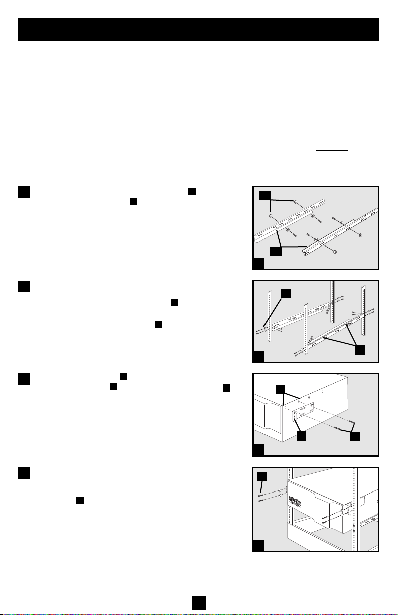
4-Post Mounting
All UPS models include hardware required to mount in a 4-post rack. Select models include an
adjustable rackmount shelf kit to provide additional support. If your UPS model does not
an adjustable rackmount shelf kit, skip steps 1 and 2.
include
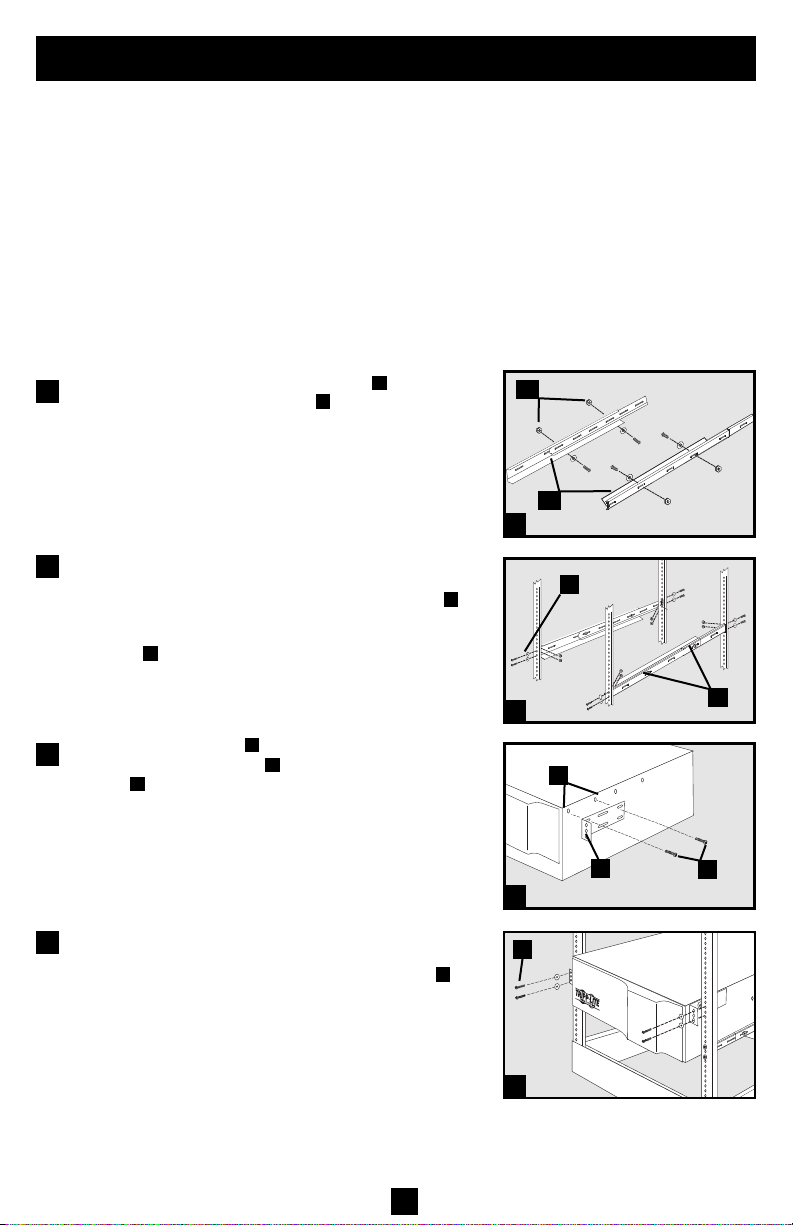
Connect the two segments of each shelf using the
1
included screws and nuts . Leave the screws slightly
B
A
loose so that the shelves can be adjusted in the next step.
Adjust each shelf to fit your rack, then mount them in
2
the lowest available space of your rack with the
screws, nuts and washers provided . Note that the
C
support ledges should face inward. Tighten the screws
that connect the shelf segments .
Attach mounting ears to the front mounting holes
3
of your equipment using the screws provided .
D
E
B
The ears should face forward.
Using an assistant if necessary, lift your equipment
4
and slide it onto the mounting shelves. Attach your
equipment to the rack by using the appropriate
hardware through its mounting ears and into the
G
rack rails.
B
A
1
C
2
F
E
D
B
F
3
G
4
3
Page 4
Mounting (Rack)
continued
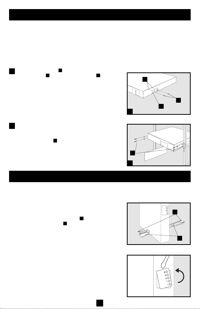
2-Post (Telecom) Mounting
Mount 1U UPS models in 2-post racks with included hardware following the procedure below.
If you mount 2U UPS models in 2-post racks, they require the addition of a Tripp Lite 2-Post
Rackmount Installation Kit (model: 2POSTRMKITWM, sold separately). See Installation Kit
owner’s manual for installation procedure for 2U UPS models.
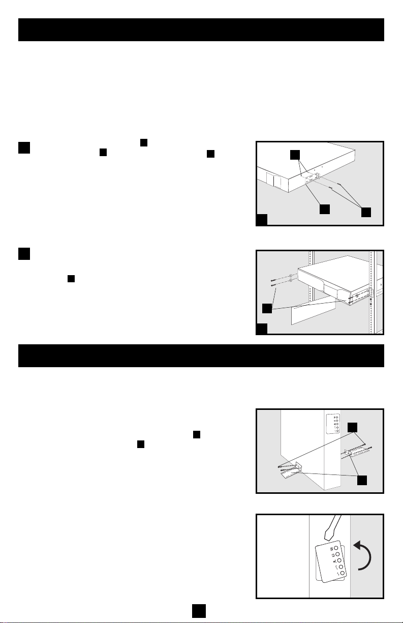
Attach mounting ears to the front mounting holes of
1
your equipment using the screws provided . The ears
should face backward.
A
CB
B
C
A
1
Using an assistant if necessary, lift your equipment
2
and slide it onto the mounting shelves. Attach your
equipment to the rack by passing the screws, nuts and
washers provided through its mounting ears and
into the rack rails.
D
D
2
Mounting (Tower)
Mount all UPS models in an upright, tower position using included hardware. The user must determine the fitness of hardware and procedures before mounting.
All UPS Models
Stand your UPS on its side with the LED/Control panel at
the top. Attach one rack mounting ear to each side of the
UPS using included screws . Attach the rack mounting
ears to the floor with user-supplied hardware.
B
A
B
2U UPS Models Only
Rotate the LED/Control panel to view it easier while the
UPS is tower mounted. Insert a small screwdriver, or other
tool, in the slots on either side of the panel. Pop the panel
out; rotate it; and pop the panel back in place.
4
A
Page 5
Quick Installation
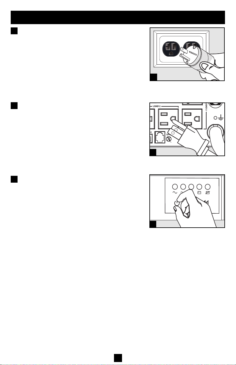
1
Plug the UPS into an outlet on a
dedicated circuit.*
NOTE! after you plug the UPS into a live AC outlet,
the UPS (in “Standby” mode) will automatically
charge its batteries,** but will not supply power to
its outlets until it is turned ON (see Step 3 below).
* Select models include an additional plug which can be switched by
a qualified electrician. ** The BATTERY CHARGE LED will be the
only LED illuminated.
2
Plug your equipment into the UPS.*
* Your UPS is designed to support only electronic equipment. You will
overload the UPS if the total VA ratings for all the equipment you connect exceeds the UPS's Output Capacity. To find your equipment's VA
ratings, look on their nameplates. If the equipment is listed in amps,
multiply the number of amps by 120 to determine VA. (Example: 1 amp
× 120 = 120 VA). If you are unsure if you have overloaded the UPS's outlets, see “OUTPUT LOAD LEVEL” LED description.
3
Turn the UPS ON.
Press and hold the “ON/OFF/STANDBY” button for
one second. The alarm will beep once briefly after one
second has passed. Release the button.
1
SMART2200RMXL2U plug
(NEMA 5-20P) shown
2
SMART3000RM2U shown
3
5
Page 6
Optional Installation
These connections are optional. Your UPS will function
properly without these connections. Note: SMART3000RM2U
shown in all diagrams.
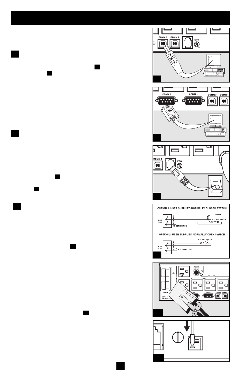
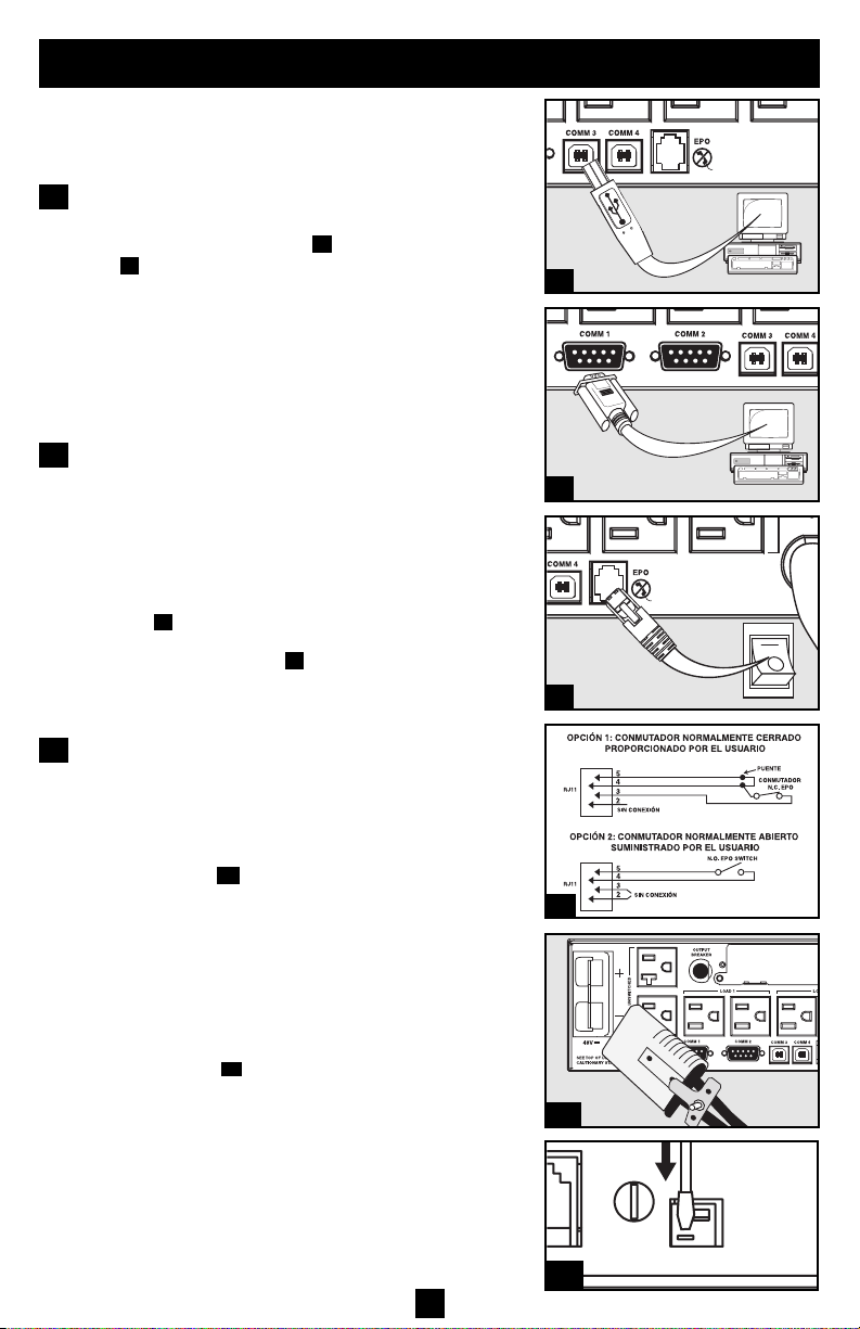
USB and RS-232 Serial
1
Communications (all models)
Use the included USB cable (see ) and/or DB9 serial
cable (see ) to connect the communication port on
your computer to the communication port of your
UPS. Install on your computer the Tripp Lite
PowerAlert Software appropriate to your computer’s
operating system. Your UPS may feature additional
communications ports; these ports may also be connected
to additional computers which have PowerAlert
Software installed. Consult your PowerAlert manual
for more information.
EPO Port Connection (all models)
2
This optional feature is only for those applications
which require connection to a facility’s Emergency
Power Off (EPO) circuit. When the UPS is connected
to this circuit, it enables emergency shutdown of the
UPS’s inverter.
Using the cable provided, connect the EPO port of
your UPS (see ) to a user-supplied normally closed or
normally open switch according to the circuit diagram
(see ). The EPO port is not a phone line surge suppressor; do not connect a phone line to this port.
External Battery Connection
3
1b
2a
2b
(select models only)
Your UPS comes with a robust internal battery system; external batteries are needed only to extend runtime. Adding external batteries will increase recharge
time as well as runtime.
The illustration (see ) shows the location of your
UPS’s External Battery Connector, where you will
insert the battery pack cable. Complete installation
instructions for your battery pack appear in the battery
pack owner’s manual. Make sure that cables are fully
inserted into their connectors. Small sparks may result
during battery connection; this is normal.
Do not connect or disconnect battery packs when the
UPS is running on battery power.
If you connect any external batteries, set the Battery
Charge Level Switch (see ) to the down position.
This will increase your UPS’s charger output so that
the additional batteries charge faster. Note: The switch
to the right of the Battery Charge Level Switch is inactive
and will not affect UPS operation regardless of its position.
Caution! DO NOT set the Battery Charge Level
Switch to the down position without an external
battery connected. There is a risk of damaging the
UPS’s internal battery system.
3a
1a
3b
6
1a
1b
2a
4-5
2b
3a
3b
Page 7
Basic Operation
Buttons (Front Panel)
“ON/OFF/STANDBY” Button
• To turn the UPS ON: with the UPS plugged into a live AC wall outlet*, press
and hold the “ON/OFF/STANDBY” button for one second.** Release the button. If utility power is absent, you can “cold-start” the UPS (i.e.: turn it ON and
supply power for a limited time from its batteries***) by pressing and holding
the “ON/OFF/STANDBY” button for one second.**
• To turn the UPS OFF: with the UPS ON and receiving utility power, press and
hold the “ON/OFF/STANDBY” button for one second.** Then unplug the UPS
from the wall outlet. The UPS will be completely OFF.
* After you plug the UPS into a live AC outlet, the UPS (in ”Standby” mode) will automatically charge
its batteries, but will not supply power to its outlets until it is turned ON. ** The alarm will beep once
briefly after the indicated interval has passed. *** If fully charged.
“MUTE/TEST” Button
To Silence (or “Mute”) UPS Alarms: briefly press and release the MUTE/TEST
button.*
To Run a Self-Test: with your UPS plugged in and turned ON, press and hold
the MUTE/TEST button for two seconds.* Continue holding the button until
the alarm beeps several times and the UPS performs a self test. See “Results of
a Self-Test” below. Note: you can leave connected equipment on during a self-test.
Your UPS, however, will not perform a self-test if the UPS is not turned on (see
“ON/OFF/STANDBY” Button description).
CAUTION! Do not unplug your UPS to test its batteries. This will remove
safe electrical grounding and may introduce a damaging surge into your
network connections.
Results of a Self-Test: The test will last approximately 10 seconds as the
UPS switches to battery to test its load capacity and battery charge.
• If the “OUTPUT LOAD LEVEL” LED remains lit red and the alarm continues to sound after the test, the UPS’s outlets are overloaded. To clear the overload, unplug some of your equipment and run the self-test repeatedly
until the “OUTPUT LOAD LEVEL” LED is no longer lit red and the
alarm is no longer sounding.
CAUTION! Any overload that is not corrected by the user immediately
following a self-test may cause the UPS to shut down and cease supplying
output power in the event of a blackout or brownout.
• If the “BATTERY WARNING” LED remains lit and the alarm continues
to sound after the test, the UPS batteries need to be recharged or
replaced. Allow the UPS to recharge continuously for 12 hours, and
repeat the self-test. If the LED remains lit, contact Tripp Lite for service.
If your UPS requires battery replacement, visit www.tripplite.com to
locate the specific Tripp Lite replacement battery for your UPS.
* The alarm will beep once briefly after the indicated interval has passed.
7
Page 8
Basic Operation
continued
Indicator Lights (Front Panel)
All Indicator Light descriptions apply when the UPS is plugged into a wall outlet
and turned ON.
“POWER” LED: this green LED lights continuously when the UPS is ON and
supplying connected equipment with AC power from a utility source. The LED
flashes and an alarm sounds (4 short beeps followed by a pause) to indicate the
UPS is operating from its internal batteries during a blackout or severe
brownout. If the blackout or severe brownout is prolonged, you should save
files and shut down your equipment since internal battery power will eventually be depleted. See “BATTERY CHARGE” LED description below.
“VOLTAGE CORRECTION” LED: this green LED lights continuously
whenever the UPS is automatically correcting high or low AC voltage on the
utility line without the assistance of battery power. The UPS will also emit a
slight clicking noise. These are normal, automatic operations of the UPS, no
action is required on your part.
“OUTPUT LOAD LEVEL” LED: this multicolored LED indicates the
approximate electrical load of equipment connected to the UPS's AC outlets. It
will turn from green (light load) to yellow (medium load) to red (overload). If
the LED is red (either illuminated continuously or flashing), clear the overload
immediately by unplugging some of your equipment from the outlets until the
LED changes from red to yellow (or green). CAUTION! Any overload that is
not corrected by the user immediately may cause the UPS to shut down and
cease supplying output power in the event of a blackout or brownout.
“BATTERY CHARGE” LED: when the UPS is operating from utility power,
this LED indicates the approximate charge state of the UPS's internal batteries:
red indicates the batteries are beginning to charge; yellow indicates the batteries
are roughly midway through charging; and green indicates the batteries are fully
charged. When the UPS is operating from battery power during a blackout or
severe brownout, this LED indicates the approximate amount of energy (ultimately affecting runtime) which the UPS’s batteries will provide: red indicates
a low level of energy; yellow indicates a medium level of energy; and green
indicates a high level of energy. Since the runtime performance of all UPS batteries will gradually deplete over time, it is recommended that you periodically
perform a self-test (see MUTE/TEST Button description) to determine the energy
level of your UPS batteries BEFORE a blackout or severe brownout occurs.
During a prolonged blackout or severe brownout, you should save files and shut
down your equipment since battery power will eventually be depleted. When the
LED turns red and an alarm sounds continuously, it indicates the UPS's batteries
are nearly out of power and UPS shut down is imminent.
“BATTERY WARNING” LED: this LED lights red and an alarm sounds
intermittently after you initiate a self test (See “MUTE/TEST” Button description)
to indicate the UPS batteries need to be recharged or replaced. Allow the UPS
to recharge continuously for 12 hours, and repeat the self-test. If the LED continues to light, contact Tripp Lite for service. If your UPS requires battery
replacement, visit www.tripplite.com to locate the specific Tripp Lite replacement battery for your UPS.
8
Page 9
Basic Operation
continued
Other UPS Features (Rear Panel)
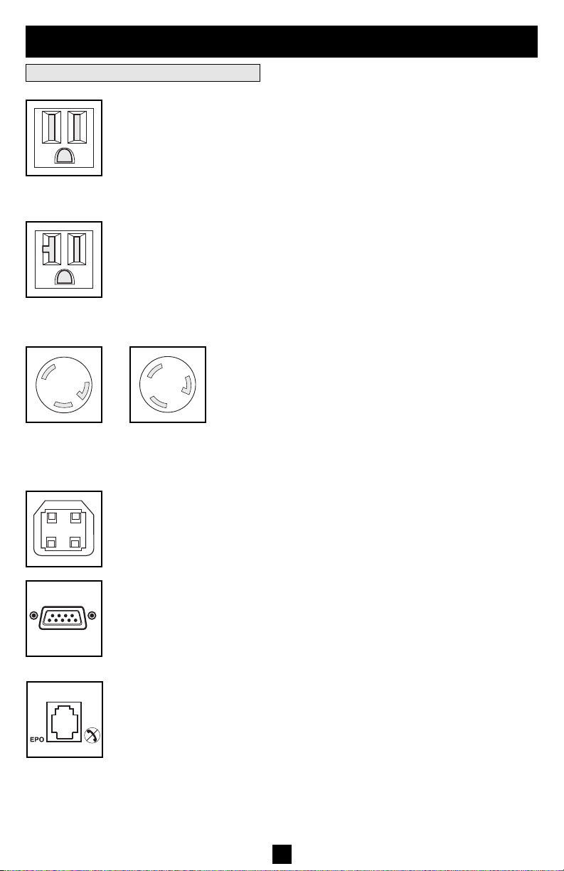
AC Receptacles: Your UPS features 15-amp AC outlets, and select models also
feature 20-amp and 30- amp AC outlets. These output receptacles provide your
connected equipment with AC line power during normal operation and battery
power during blackouts and brownouts. The UPS protects equipment connected to these receptacles against damaging surges and line noise. If you have a
15 amp/120V
NEMA 5-15R
20 amp/120V
NEMA 5-20R
serial or USB connection to your UPS, you can remotely reboot connected equipment by turning the receptacles OFF and ON using Tripp Lite's PowerAlert
Software. Select models have their receptacles divided into one or more load
banks (labelled “LOAD 1,” etc.) which may be remotely switched OFF and ON
using Tripp Lite UPS software without interrupting power to equipment connected to the other outlets. Select models feature special outlets (clearly labeled
on the rear panel) which provide surge-only (not battery backup) protection
designed for laser printers and other heavy-draw devices. Select models also
feature outlets labelled “UNSWITCHED”, which may not be remotely
switched off. See software instructions for details.
30 amp/120V
NEMA L5-30R
20 amp/120V
NEMA L5-20R
Communications Ports (USB or RS-232): These ports connect your UPS to any
workstation or server. Use with Tripp Lite’s PowerAlert Software and included
cables to enable your computer to automatically save open files and shut down
equipment during a blackout. Also use PowerAlert Software to monitor a wide
variety of AC line power and UPS operating conditions. Consult your
PowerAlert Software manual or contact Tripp Lite Customer Support for more
information. See “USB and RS-232 Serial Communications” in the “Optional
Installation” section for installation instructions.
EPO (Emergency Power Off) Port: Your UPS features a EPO port that may
be used to connect the UPS to a contact closure switch to enable emergency
inverter shutdown. See Optional Installation.
9
Page 10
Basic Operation
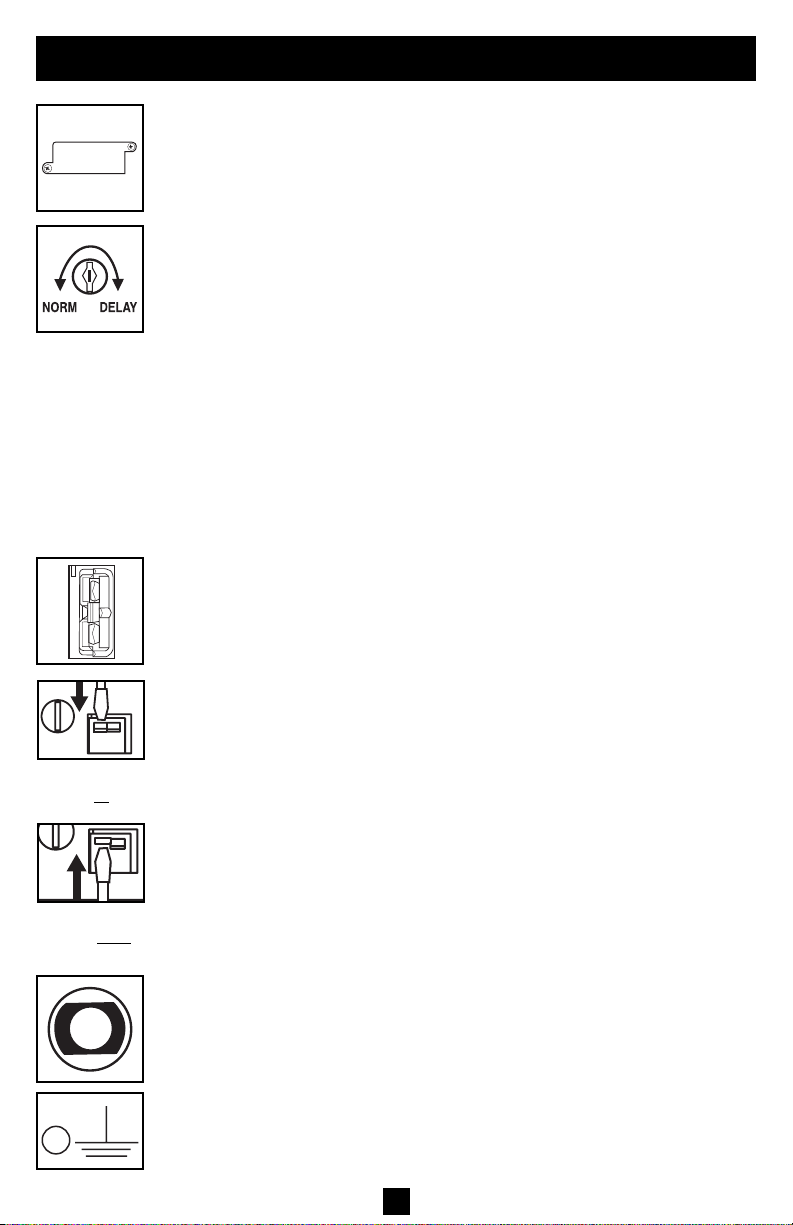
Accessory Slot: Remove the small cover panel from this slot to install optional
accessories to remotely monitor and control your UPS. Refer to your accessory’s
manual for installation instructions. Contact Tripp Lite Customer Support at
(773) 869-1234 for more information, including a list of available SNMP, network
management and connectivity products.
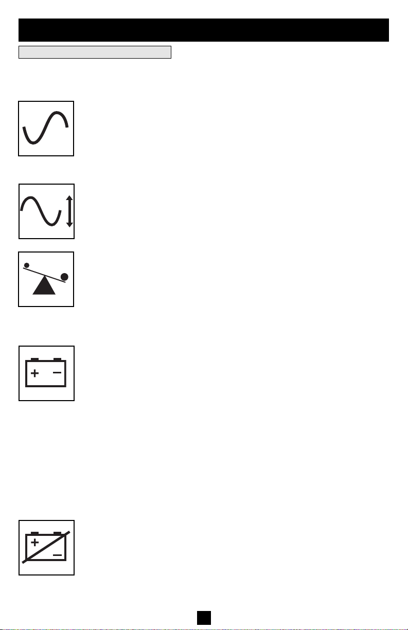
Power Sensitivity Adjustment: This dial is normally set fully counter-clockwise,
which enables the UPS to provide maximum protection against waveform distortions
in its AC input. When such distortion occurs, the UPS will normally switch to
providing sine wave power from its battery reserves for as long as the
distortion is present. In areas with poor utility power or where the UPS’s input
power comes from a backup generator, chronic waveform distortion could
cause the UPS to switch to battery too frequently, draining its battery reserves.
You may be able to reduce how often your UPS switches to battery due to moderate waveform distortion by experimenting with different settings for this dial.
As the dial is turned clockwise, the UPS becomes more tolerant of variations in
its input power’s AC waveform. NOTE: The further the dial is adjusted clockwise,
the greater the degree of waveform distortion the UPS will allow to pass to connected equipment. When experimenting with different settings for this dial,
operate connected equipment in a safe test mode so that the effect on the equipment of any waveform distortions in the UPS’s output can be evaluated without
disrupting critical operations.
External Battery Connector (Select Models Only): Use to connect Tripp Lite
external battery packs for additional runtime. Refer to instructions available with
the battery pack for complete connection information and safety warnings.
continued
Charge Rate Setting
(when External
e con-
Batteries ar
nected)
Charge Rate Setting
(when External
e not
Batteries ar
connected)
Battery Charge Level Switch (Select Models Only): Controls the UPS system’s
battery charge rate. If you connect any external batteries, set the Battery Charge
Level Switch to the down position. This will increase your UPS's charger output
so the additional batteries charge faster. Note: the switch to the right of the
Battery Charge Level Switch is inactive and will not affect UPS operation
regardless of its position. CAUTION! DO NOT set the Battery Charge Level
Switch to the down position without an external battery connected. There
is a risk of damaging the UPS’s internal battery system.
Input Breaker(s) (all models): Protect your electrical circuit from overcurrent
draw from the UPS load. If these breakers trip, remove some of the load, then
reset them by pressing the breaker(s) in.
Output Breaker (select models): Your UPS features one or more breakers that
protect your UPS from output overload. If one or more breakers trip, remove
some of the load on the circuit(s), then reset them by pressing the breaker
switch(es) in.
Ground Screw: Use this to connect any equipment that requires a chassis ground.
10
Page 11

Storage and Service
Storage
Before storing your UPS, turn it completely OFF: with the UPS ON and receiving utility power, press
and hold the "ON/OFF/STANDBY" button for one second (an alarm will beep once briefly after the
interval has passed); then, unplug the UPS from the wall outlet. If you store your UPS for an extended period of time, recharge the UPS batteries once every three months: plug the UPS into a wall outlet; allow it to charge for 12 hours; and then unplug it and place it back in storage. Note: after you plug
the UPS in, it will automatically begin charging its batteries; however, it will not supply power to its
outlets (see Quick Installation section). If you leave your UPS batteries discharged for an extended
period of time, they will suffer a permanent loss of capacity.
Service
Before returning your UPS for service, follow these steps:
1. Review the installation and operation instructions in this manual to ensure that the service
problem does not originate from a misreading of the instructions. Also, check that the UPS
System's circuit breaker(s) are not tripped. This is the most common cause of service inquiries
which can be easily remedied by following the resetting instructions in this manual.
2. If the problem continues, do not contact or return the UPS to the dealer. Instead, call Tripp Lite
at (773) 869-1233. A service technician will ask for the UPS's model number, serial number
and purchase date and will attempt to correct the problem over the phone.
3. If the problem requires service, the technician will issue you a Returned Material Authorization
(RMA) number, which is required for service. If you require packaging, the technician can
arrange to send you proper packaging. Securely pack the UPS to avoid damage during shipping.
Do not use Styrofoam beads for packaging. Any damages (direct, indirect, special, incidental
or consequential) to the UPS incurred during shipment to Tripp Lite or an authorized Tripp Lite
service center is not covered under warranty. UPS Systems shipped to Tripp Lite or an authorized
Tripp Lite service center must have transportation charges prepaid. Mark the RMA number on
the outside of the package. If the UPS System is within the 2-year warranty period, enclose a
copy of your sales receipt. Return the UPS for service using an insured carrier to the address
given to you by the Tripp Lite service technician.
11
Page 12

Battery Replacement
Under normal conditions, the original batteries in your UPS will last many years. See Safety section before replacing batteries. The batteries are designed for hot-swap replacement (i.e. leaving the
UPS in ON mode), but some qualified service personnel may wish to put the UPS in the OFF mode
and disconnect equipment before proceeding.
1U UPS Models
®
UPS
RO
P
MART
S
1
2
3
®
UPS
RO
P
MART
S
1
2U UPS Models
6
Procedure
1
Remove Front
Panel
2
Disconnect
6
Batteries
3
Remove/Dispose of
Batteries
4
Add Batteries
5
Connect Batteries
Attach connectors: blackto-black and red-to-red.
5
6
Replace
Front
2
5
Panel
4
3
4
FCC RADIO/TV INTERFERENCE NOTICE: (FOR CLASS A MODELS)
Note: This equipment has been tested and found to comply with the limits for a Class Adigital device, pursuant to Part 15 of the FCC Rules. These limits are designed to provide reasonable protection
against harmful interference when operated in a commercial environment. This equipment generates, uses and can radiate radio frequency energy, and if not installed and used in accordance with
the instruction manual, may cause interference to radio communications. Operation of this equipment is likely to cause harmful interference in which case the user will be required to correct the interference
at his own expense. The user must use shielded cables and connectors with this product. Any changes or modifications to this product not expressly approved by the party responsible for compliance
could void the user's authority to operate the equipment.
FCC RADIO/TV INTERFERENCE NOTICE: (FOR CLASS B MODELS)
Note: This equipment has been tested and found to comply with the limits for a Class B digital device, pursuant to Part 15 of the FCC Rules. These limits are designed to provide reasonable protection
against harmful interference in a residential installation. This equipment generates, uses and can radiate radio frequency energy, and if not installed and used in accordance with the instruction manual,
may cause interference to radio communications. However, there is no guarantee that interference will not occur in a particular installation. If this equipment does cause harmful interference to radio or
television reception, which can be determined by turning the equipment off and on, the user is encouraged to try to correct the interference using one or more of the following measures: reorient or relocate
the receiving antenna; increase the separation between the equipment and the receiver; connect the equipment into an outlet on a circuit different from that which the receiver is connected; consult
the dealer or an experienced radio/television technician for help. The user must use shielded cables and connectors with this product. Any changes or modifications to this product not expressly
approved by the party responsible for compliance could void the user’s authority to operate the equipment. This device complies with part 15 of the FCC rules. Operation is subject to the following 2 conditions:
(1) This device may not cause harmful interference, and (2) This device must accept any interference received, including interference that may cause undesired operation.
Regulatory Compliance Identification Numbers
For the purpose of regulatory compliance certifications and identification, your Tripp Lite product has been assigned a unique series number. The series number can be found on the product nameplate label, along with all required approval markings and information. When requesting compliance information for this product, always refer to the series number. The series number should not be
confused with the marking name or model number of the product.
Note on Labeling
Two symbols are used on the label.
V~ : AC Voltage
V : DC Voltage
12
Page 13

Manual del propietario
Sistemas UPS SmartPro
para montaje en bastidor
Inteligentes e interactivos con la línea
• Entrada/salida de onda sinusoidal de 120V*
• Capacidad entre 500 y 3000 VA • Opciones de tiempo de respaldo extendido
* Excepto el SMART500RT1U: salida de onda sinusoidal con la línea; salida de PWM con baterías
Instrucciones de seguridad importantes
Montaje
Instalación rápida
Instalación opcional
Operación básica
Almacenamiento y servicio
®
14
15
17
18
19
23
Reemplazo de batería
English
Français
1111 W. 35th Street Chicago, IL 60609 USA
Soporte al cliente: (773) 869-1234 • www.tripplite.com
Copyright ©2004 Tripp Lite. Todos los derechos reservados. SmartPro®es una marca comercial registrada de Tripp Lite.
24
1
25
13
Page 14

Instrucciones de seguridad importantes
GUARDE ESTAS INSTRUCCIONES
Este manual contiene importantes instrucciones que deben seguirse durante la instalación, operación y el
almacenamiento de todos los UPS de Tripp Lite. La no observancia de estas advertencias anulará su garantía.
Advertencias sobre la ubicación del UPS
• Tenga cuidado al levantar el UPS. Debido al gran peso de los UPS para montaje en bastidor, se requieren
por lo menos dos personas para que le ayuden a levantarlos e instalarlos.
• Instale su UPS bajo techo, lejos de la humedad, el calor, el polvo o la luz solar directa.
• Para un mejor funcionamiento, la temperatura ambiente cerca de su UPS debe estar entre 0° C y 40° C
(32° F - 104° F)
• Deje una cantidad adecuada de espacio alrededor de todos los lados del UPS para sua adecuada
ventilación. No obstruya sus respiraderos ni las aberturas de ventilación.
Advertencias sobre la conexión del UPS
• El UPS contiene su propia fuente de energía (batería) Los terminales de salida pueden estar con energía
incluso cuando el UPS no está conectado a un suministro de corriente alterna.
• Conecte su UPS a una toma de CA puesta a tierra apropiadamente. No modifique el enchufe del UPS en
ninguna forma que elimine su conexión a tierra. No use adaptadores que eliminen la conexión del UPS a tierra.
• No conecte el UPS a si mismo ya que podría dañarse y anular la garantía.
• Si va a conectar su UPS a un generador de corriente alterna accionado por un motor, el generador debe
suministrar una salida filtrada, con regulación por frecuencia grado computadora. La conexión de su UPS
a un generador anulará su seguro Ultimate de por vida.
Advertencias sobre la conexión de equipos
• No utilice sistemas UPS de Tripp Lite para aplicaciones de soporte de vida en las que un funcionamiento
defectuoso o una falla del UPS pudiera causar un mal funcionamiento o una alteración importante en el
funcionamiento de un dispositivo de soporte de vida.
• No conecte supresores de sobretensiones ni cordones de extensión a la salida de su UPS. Esto puede
sobrecargarlo y anular su garantía y la del supresor de sobretensiones.
Advertencias sobre la batería
• Las baterías presentan un peligro de choque eléctrico y quemaduras debido a las altas corrientes de corto-
circuito. Observe las precauciones apropiadas. No deseche las baterías en un incinerador. No abra el UPS
ni las baterías. No ponga los terminales de la batería en corto o en puente con ningún objeto. Apague y
desconecte el UPS antes de reemplazar la batería. Use herramientas con mangos aislados. No hay piezas
que el usuario pueda reparar dentro del UPS. El reemplazo de baterías debe ser realizado solamente por
personal de servicio autorizado usando el mismo número y tipo de baterías (plomo-ácido, selladas). Las
baterías son reciclables. Consulte la reglamentación local para los requisitos de disposición de desechos;
en los EE.UU. llame al 1-800-SAV-LEAD o al 1-800-8-BATTERY (1-800-8-228-8379) o visite
www.rbrc.com para obtener información sobre el proceso de reciclaje. Tripp Lite ofrece una línea completa de cartuchos de reemplazo de batería para UPS (R.B.C.) Visite la página web de Tripp Lite en
www.tripplite.com para localizar la batería de reemplazo específica para su UPS.
• Durante el reemplazo de baterías en operación (hot-swap), el UPS no proporcionará energía de respaldo
en el caso de una falla del servicio eléctrico u otras interrupciones de energía.
• No opere el UPS sin baterías.
• Al agregar bancos de baterías externas a modelos exclusivos con conectores para este tipo de bancos, sólo
emplee bancos recomendados por Tripp Lite del voltaje y tipo correctos. No conecte ni desconecte bancos
de baterías cuando el UPS esté funcionando con energía de las baterías.
14
Page 15
Montaje (Bastidor)
Monte su equipo en un bastidor de 2 o 4 postes (vea la siguiente página para información sobre el montaje de 2
postes) El usuario debe determinar la idoneidad de los materiales y accesorios, así como de los procedimientos antes
del montaje. Si los materiales y procedimientos no son adecuados para su aplicación, contacte con el fabricante
de su bastidor. Los procedimientos descritos en este manual son para bastidores comunes y de tipo caja y podrían
no ser apropiados para todas las aplicaciones.
Montaje de 4 postes
Todos los modelos de UPS incluyen los accesorios requeridos para montar un bastidor de 4 postes. Los modelos
exclusivos incluyen un kit de anaquel ajustable para montaje en bastidor a fin de proporcionar un apoyo adicional.
Si su modelo de UPS no incluye este kit, omita los pasos 1 y 2.
Conecte los dos segmentos de cada anaquel usando los
1
tornillos y las tuercas de mariposa incluidos. Deje los
tornillos ligeramente flojos de modo que los anaqueles
puedan ajustarse en el siguiente paso.
Ajuste cada anaquel para que se adapte a su bastidor, y luego
2
instálelos en el espacio más bajo disponible del mismo con
las tuercas, las arandelas y los tornillos suministrados .
Note que los bordes de apoyo deben mirar hacia adentro.
Apriete los tornillos que conectan los segmentos de los
anaqueles .
Fije las orejas de montaje a los agujeros de montaje de la
3
parte delantera de su equipo usando los tornillos suministrados . Las orejas deben mirar hacia adelante.
Con la ayuda de otra persona si fuera necesario, levante su
4
equipo y deslícelo en los anaqueles de montaje. Fije su
equipo al bastidor usando los accesorios suministrados a
través de las orejas de montaje y dentro de los rieles del
bastidor.
B
D
E
F
A
B
B
A
1
C
C
2
B
E
D
F
3
G
G
15
4
Page 16

Montaje (en bastidor)
continúa
Montaje de 2 postes (Telecomunicaciones)
Monte los modelos de UPS de 1U en bastidores de 2 postes usando los accesorios incluidos y siguiendo el procedimiento indicado a continuación.
Si monta un modelo de UPS de 2U en bastidores de 2 postes, necesitará agregar un kit de instalación para montaje
en bastidor de 2 postes de Tripp Lite (modelo: 2POSTRMKITWM, vendido por separado) Vea el manual del propietario del kit para conocer el procedimiento de instalación en los modelos de 2U.
Fije las orejas de montaje a los agujeros de montaje de la
1
parte delantera de su equipo usando los tornillos sumin-
C
istrados . Las orejas deben mirar hacia atrás.
A
B
B
C
A
1
Con la ayuda de otra persona si fuera necesario, levante su
2
equipo y deslícelo en los anaqueles de montaje. Fije su
equipo al bastidor pasando los tornillos, las tuercas y las
arandelas suministrados a través de las orejas de montaje
y dentro de los rieles del bastidor.
D
D
2
Montaje (En torre)
Monte todos los modelos de UPS en una posición vertical, de torre, usando los accesorios incluidos. El usuario debe
determinar la idoneidad de los materiales y accesorios así como de los procedimientos antes del montaje.
Tolos los modelos de UPS
Coloque su UPS sobre la parte lateral y con el panel LED/de control
en la parte superior. Fije una oreja de montaje del bastidor a cada
lado del UPS usando los tornillos incluidos. Fije las orejas de
montaje del bastidor al piso con accesorios suministrados por el
usuario.
B
A
B
Modelos de UPS de 2U solamente
Gire el panel LED/de control para su mejor visibilidad mientras el
UPS está montado en torre. Introduzca un pequeño destornillador u
otra herramienta en las ranuras en cualquier lado del panel. Saque
el panel, gírelo y colóquelo en posición nuevamente.
16
A
Page 17

Instalación rápida
Conecte el UPS en una salida de un
1
circuito dedicado.*
NOTADespués de conectar el UPS en una toma de corriente
alterna con energía, el equipo (en modo "Standby") cargará
automáticamente sus baterías,** pero no suministrará
energía a sus salidas hasta que sea encendido (vea más abajo
el Paso 3)
* Los modelos exclusivos incluyen un enchufe que puede ser conectado a un interruptor por un electricista calificado. ** El LED de BATTERY CHARGE (CARGA
DE BATERÍA) será el único iluminado.
Conecte sus equipos en el UPS.*
2
* Su UPS sólo está diseñado para dar soporte a equipos electrónicos. Si la
capacidad total en VA para todos los equipos conectados a las salidas protegidas
por baterías de reserva / protegidas contra sobretensión excede la capacidad de
salida del UPS, éste se sobrecargará Para averiguar la capacidad de sus equipos
en VA, revise sus placas. Si la capacidad del equipo está indicada en amperios,
multiplique los amperios por 120 para determinar los VA. (Ejemplo: 1 amperio
× 120 = 120 VA) Si no está seguro de si ha sobrecargado las salidas del UPS,
consulte la descripción del LED “OUTPUT LOAD LEVEL” (NIVEL DE CARGA
DE SALIDA)
Encienda el UPS.
3
Presione y mantenga presionado el botón "ON/OFF/STANDBY" (Encendido/Apagado/Reserva) durante un segundo. La
alarma emitirá un pitido brevemente después de pasado un
segundo. Suelte el botón.
1
Enchufe SMART2200RMXL2U
(NEMA 5-20P) mostrado
2
SMART3000RM2U mostrado
17
3
Page 18
Instalación opcional
Estas conexiones son opcionales. Su UPS funcionará correctamente sin ellas. Nota: Modelo SMART3000RM2U mostrado en
todos los diagramas.
1
Comunicaciones USB y serie RS-232
(todos los modelos)
Use el cable USB incluido (vea ) y/o el cable serie DB9
1b
(vea ) para conectar el puerto de comunicaciones de su
computadora al puerto de comunicaciones de su UPS. Instale
en su computadora el software PowerAlert de Tripp Lite
apropiado para su sistema operativo. Su UPS puede tener
puertos adicionales de comunicaciones; estos puertos también
pueden estar conectados a computadoras adicionales con el
software PowerAlert instalado. Consulte su manual de
PowerAlert para mayor información.
Conexión de puerto EPO
2
(todos los modelos)
Esta característica opcional es sólo para aquellas aplicaciones que requieran una conexión al circuito de desconexión
de emergencia (EPO) de la instalación Cuando el UPS está
conectado a este circuito, permite el apagado de emergencia
del inversor del UPS.
Usando el cable suministrado, conecte el puerto EPO de su
UPS (vea ) a un contacto normalmente cerrado o normalmente abierto suministrado por el usuario, de acuerdo con el
diagrama del circuito (vea ) El puerto EPO no es un
supresor de sobretensiones de línea telefónica; no conecte
una línea telefónica en este puerto.
2a
1a
2b
1a
1b
2a
3
Conexión de batería externa
(modelos exclusivos)
Su UPS incluye un robusto sistema de batería interna; las
baterías externas sólo son necesarias para prolongar el tiempo de respaldo.Al agregar baterías externas, aumentará el
tiempo de recarga así como el tiempo de respaldo.
La ilustración (vea ) muestra la ubicación del conector de
batería externa de su UPS donde debe introducir el cable del
banco de baterías. Vea las instrucciones completas de instalación para su banco de baterías en el manual del propietario del
banco de baterías. Asegúrese que los cables estén introducidos
completamente en sus conectores. Durante la conexión de la
batería pueden producirse pequeñas chispas; esto es normal.
No conecte ni desconecte bancos de baterías cuando el UPS
esté funcionando con energía de las baterías.
Si conecta alguna batería externa, fije el Interruptor de nivel
de carga de batería ( ) en la posición de abajo. Esto aumentará la salida del cargador del UPS a fin de que baterías adicionales se carguen más rápido. Nota: el interruptor a la derecha
del interruptor de nivel de carga está inactivo y no afectará la
operación del UPS, independientemente de su posición.
¡PRECAUCIÓN! NO fije el Interruptor de nivel de carga de
batería en la posición de abajo sin una batería externa conectada.
Podría dañar el sistema de la batería interna del UPS.
3a
3b
4-5
2b
3a
3b
18
Page 19

Operación básica
Botones (Panel frontal)
Botón "ON/OFF/STANDBY" (Encendido/Apagado/Reserva)
• Para encender el UPS: Con el UPS conectado en una toma de CAcon energía*, presione
y mantenga presionado el botón "ON/OFF/STANDBY" (Encendido/Apagado/Reserva)
por un segundo.** Suelte el botón. Si no hay energía de la red, puede "arrancar en frío" el
UPS (es decir, encenderlo y suministrar energía de sus baterías por un tiempo limitado***)
presionando y manteniendo presionado el botón "ON/OFF/STANDBY" (Encendido/
Apagado/Reserva) durante un segundo.**
• Para apagar el UPS: Con el UPS encendido y recibiendo energía de la red, presione y
mantenga presionado el botón "ON/OFF/STANDBY" (Encendido/Apagado/Reserva)
durante un segundo.** Luego desconecte el UPS de la toma de corriente. El UPS se
apagará.
* Después de conectar el UPS en una toma de CA con energía, el equipo (en modo "Standby") cargará automáticamente sus baterías, pero no suministrará energía a sus salidas hasta que sea encendido. ** La alarma emitirá un pitido brevemente después de pasado el intervalo indicado. *** Si está completamente cargada.
Botón "MUTE/TEST" (SILENCIO/PRUEBA)
Para silenciar las alarmas UPS: Presione brevemente el botón MUTE/TEST (SILEN-
CIO/PRUEBA) y luego suéltelo.
Para ejecutar una auto-prueba: Con su UPS conectado y encendido, presione y mantenga
presionado el botón MUTE/TEST (Silencio/Prueba) por dos segundos.*Siga presionando el
botón hasta que la alarma suene varias veces y el UPS realice una auto-prueba. Vea
"Resultados de una auto-prueba" más abajo. Nota: Puede dejar equipos conectados durante
una auto-prueba. Sin embargo, el UPS, no realizará una auto-prueba si no está encendido
(vea la descripción del Botón "ON/OFF/STANDBY").
¡PRECAUCIÓN! No desconecte su UPS para probar sus baterías. Esto eliminaría la
conexión de seguridad a tierra y podría introducir una sobretensión dañina en sus
conexiones de red.
Resultados de una auto-prueba: La prueba durará cerca de 10 segundos mientras el
UPS conmuta a batería para probar su capacidad de carga y la recarga de la batería.
• Si el LED "OUTPUT LOAD LEVEL" (NIVEL DE CARGA DE SALIDA) permanece encendido rojo y la alarma continúa sonando después de la prueba, las salidas del UPS están sobrecargadas. Para eliminar la sobrecarga, desconecte algo de
su equipo y ejecute la auto-prueba repetidamente hasta que el LED ya no esté
encendido rojo y la alarma ya no esté sonando.
¡PRECAUCIÓN! Cualquier sobrecarga que no sea corregida por el usuario
inmediatamente después de una auto-prueba puede causar que el UPS se
apague y deje de suministrar energía de salida en el caso de una falla del servicio eléctrico o una baja de voltaje.
• Si el LED "BATTERY WARNING" (ADVERTENCIA DE BATERÍA) sigue
encendido y la alarma continúa sonando después de la prueba, las baterías del UPS
deben recargarse o reemplazarse. Permita que el UPS se recargue continuamente
por 12 horas y repita la auto-prueba. Si el LED permanece encendido, contacte con
Tripp Lite para obtener servicio. Si su UPS requiere el reemplazo de su batería,
visite www.tripplite.com para localizar la batería de reemplazo Tripp Lite específica para su UPS.
* La alarma emitirá un pitido brevemente después de pasado el intervalo indicado.
19
Page 20

Operación básica
(continúa)
Luces indicadoras (Panel frontal)
Todas las descripciones de luces indicadoras se aplican cuando el UPS está conectado en
un tomacorriente y encendido.
LED “POWER” (ALIMENTACIÓN): Este LED verde se enciende permanentemente
cuando el UPS está encendido y proporcionando energía de CA al equipo conectado desde
el suministro de red. El LED destella y una alarma suena (4 pitidos cortos seguidos de una
pausa) para indicar que el UPS está operando con sus baterías internas durante una falla
del servicio eléctrico o una severa baja de voltaje. Si la falla o la baja de voltaje es muy
prolongada, debe guardar sus archivos y apagar su equipo ya que la energía de la batería
interna finalmente se agotará. Vea la descripción del LED “BATTERY CHARGE”
(CARGA DE BATERÍA)
LED “VOLTAGE CORRECTION” (CORRECCIÓN DE VOLTAJE): Este LED
verde se enciende en forma permanente cuando el UPS está corrigiendo automáticamente
el voltaje de CA alto o bajo en la línea de la red sin la ayuda de energía de baterías. El
UPS también emitirá un ligero clic. Estas son operaciones normales y automáticas del
UPS y no requieren de ninguna acción de su parte.
LED “OUTPUT LOAD LEVEL” (NIVEL DE CARGADE SALIDA): Este LED multicolor indica la carga eléctrica aproximada del equipo conectado a las salidas de CA del
UPS. Se encenderá desde verde (carga ligera) a amarillo (carga media) y a rojo (sobrecarga) Si el LED está rojo (ya sea iluminado permanentemente o destellando), elimine la
sobrecarga de inmediato desconectando algo de su equipo de las salidas hasta que el LED
cambie de rojo a amarillo (o verde). ¡PRECAUCIÓN! Cualquier sobrecarga que no sea
corregida por el usuario inmediatamente puede causar que el UPS se apague y deje de
suministrar energía de salida en el caso de un falla del servicio eléctrico o una baja de voltaje.
LED “BATTERY CHARGE” (CARGA DE BATERÍA): Cuando el UPS opera con la
energía de la red, este LED indica el estado aproximado de carga de las baterías internas
del UPS; el rojo indica que las baterías están comenzando a cargarse; el amarillo indica
que las baterías están aproximadamente a media recarga; y el verde indica que las baterías
están totalmente cargadas. Cuando el UPS opera con energía de las baterías durante una
falla del servicio eléctrico o una baja de voltaje severa, este LED indica la cantidad aproximada de energía (que a fin de cuentas afecta el tiempo de respaldo) que proporcionarán
las baterías del UPS; el rojo indica un bajo nivel de energía, el amarillo un nivel mediano
y el verde un nivel alto de energía. Ya que el rendimiento del tiempo de respaldo de todas
las baterías del UPS se reducirá gradualmente, se recomienda realizar una auto-prueba
periódicamente (vea la descripción del botón MUTE/TEST (SILENCIO/PRUEBA)) para
determinar el nivel de energía de las baterías de su UPS ANTES de que ocurra una falla
del servicio eléctrico o una baja de voltaje severa. Durante una falla prolongada o una severa
baja de voltaje, debe guardar sus archivos y apagar su equipo ya que la energía de baterías
se agotará finalmente. Cuando el LED se enciende rojo y una alarma suena en forma continua,
indica que las baterías del UPS están casi sin energía y es inminente que el UPS se apague.
LED “BATTERY WARNING” (ADVERTENCIA DE BATERÍA): Este LED se
enciende rojo y una alarma suena en forma intermitente después de iniciar una auto-prueba
(vea la descripción del botón “MUTE/TEST” (SILENCIO/PRUEBA)) para indicar que
las baterías del UPS deben ser recargadas o reemplazadas. Permita que el UPS se recargue
continuamente por 12 horas y repita la auto-prueba. Si el LED sigue encendido, contacte
con Tripp Lite para que le brinden servicio. Si su UPS requiere el reemplazo de su batería,
visite www.tripplite.com para localizar la batería de reemplazo Tripp Lite específica para
su UPS.
20
20
Page 21

Operación básica
(continúa)
Otras funciones del UPS (Panel posterior)
Tomas de CA: Su UPS tiene salidas de CA de 15 amperios y los modelos exclusivos también
tienen salidas de 20 y 30 amperios. Estas salidas proporcionan energía de la línea de corriente
alterna a su equipo conectado durante operación normal, y energía de baterías durante fallas
del servicio eléctrico y bajas de voltaje. El UPS protege al equipo conectado a estas tomas
contra sobretensiones perjudiciales y ruido en la línea. Si tiene una conexión serie o USB
a su UPS, puede reiniciar en forma remota el equipo conectado desactivando las salidas
15 A/120V
NEMA 5-15R
20 A/120V
NEMA 5-20R
y activándolas nuevamente, usando el software PowerAlert de Tripp Lite. Los modelos
exclusivos tienen sus receptáculos divididos en uno o más bancos de carga (rotulados
“LOAD 1” (CARGA 1), etc.) que pueden ser encendidos y apagados en forma remota
usando software de UPS de Tripp Lite sin interrumpir la energía al equipo conectado a las
otras salidas. Los modelos exclusivos presentan salidas especiales (claramente rotuladas
en el panel posterior) que sólo proporcionan protección contra sobretensiones (no brindan
respaldo de batería), diseñadas para impresoras láser y otros dispositivos de alto consumo. Los modelos exclusivos también tienen salidas rotuladas “UNSWITCHED” (SIN
CONTROL POR INTERRUPTOR), que no pueden ser apagadas en forma remota. Vea
las instrucciones del software para más detalles.
30 A/120V
NEMA L5-30R
20 A/120V
NEMA L5-20R
Puertos de comunicaciones (USB o RS-232): Estos puertos conectan su UPS a
cualquier estación de trabajo o servidor. Úselos con el software PowerAlert de Tripp Lite
y los cables incluidos para permitir que su computadora guarde automáticamente los
archivos abiertos y apague el equipo durante una falla del servicio eléctrico. También utilice
PowerAlert para vigilar una amplia variedad de condiciones de operación de la energía de
la línea de CA y del UPS. Consulte su manual de PowerAlert o contacte con el Soporte
al cliente de Tripp Lite para mayor información. Consulte “Comunicaciones USB y serie
RS-232” en la sección “Instalación opcional” para obtener la información sobre las
instrucciones de instalación.
Puerto EPO (Desconexión de emergencia): Su UPS tiene un puerto EPO que puede usarse
para conectar el UPS a un contacto de cierre para permitir el apagado de emergencia del
inversor. Consulte Conexión opcional.
21
Page 22

Operación básica
Ranura auxiliar: Retire el pequeño panel de cubierta de esta ranura para instalar los
accesorios opcionales para vigilancia y control de su UPS en forma remota. Consulte el
manual de sus accesorios para instrucciones de instalación. Contacte con el Soporte al
cliente de Tripp Lite al (773) 869-1234 para mayor información, incluyendo una lista de
productos disponibles para SNMP, administración de red y conectividad.
Ajuste de sensibilidad de energía: Este dial está fijado normalmente totalmente contra
el sentido del reloj, lo que permite que el UPS proporcione una protección máxima contra
distorsiones de la forma de onda en su entrada de CA. Cuando ocurren dichas distorsiones,
normalmente el UPS conmutará para proporcionar una onda sinusoidal de energía de sus
baterías de reserva por tanto tiempo como la distorsión continúe. En áreas con un suministro de energía de la red de baja calidad, o donde la energía de entrada del UPS provenga de un generador de respaldo, la distorsión crónica de la forma de onda puede causar
que el UPS conmute a alimentación por baterías con demasiada frecuencia, agotando sus
baterías de reserva. Es posible que reduzca la frecuencia con que su UPS conmuta a
baterías moderando la distorsión de la forma de onda experimentando con diferentes ajustes
para este dial. A medida que el dial es girado en el sentido del reloj, el UPS se vuelve más
tolerante a las variaciones en la forma de onda de la energía de la CA de entrada. NOTA: A
mayor ajuste del dial en el sentido del reloj, mayor será el grado de distorsión de la forma
de onda que el UPS permitirá pasar al equipo conectado. Al experimentar con diferentes
ajustes para este dial, opere el equipo conectado en un modo de prueba seguro, de modo
que el efecto de cualquier distorsión de forma de onda en la salida del UPS sobre el
equipo pueda evaluarse sin desestabilizar ninguna operación crítica.
Conector de la batería externa (Sólo en modelos exclusivos): Úselo para conectar los
bancos de baterías externas de Tripp Lite para obtener tiempo de respaldo adicional.
Consulte las instrucciones incluidas con el banco de baterías para obtener información
completa sobre la conexión y las advertencias de seguridad.
(continúa)
Ajuste de velocidad
de carga (con
baterías externas
conectadas)
Ajuste de velocidad
de carga (sin
baterías externas
conectadas)
Interruptor de nivel de carga de batería (modelos exclusivos): Controla la velocidad
de carga de baterías del UPS. Si conecta alguna batería externa, fije el Interruptor de nivel
de carga de batería en la posición de abajo. Esto aumentará la salida del cargador del UPS
a fin de cargar más rápido baterías adicionales. Nota: El interruptor a la derecha del interruptor de nivel de carga está inactivo y no afectará la operación del UPS, independientemente de su posición. ¡PRECAUCIÓN! NO fije el Interruptor de nivel de carga de batería
en la posición de abajo sin que haya conectada alguna batería externa. Podría dañarse el
sistema de la batería interna del UPS.
Interruptor(es) automático(s) (todos los modelos): Protegen su circuito eléctrico contra
sobrecarga al UPS. Si uno de estos interruptores dispara, retire algo de carga y
restablézcalo presionando el interruptor.
Interruptor de salida (modelos exclusivos): Su UPS tiene uno o más interruptores
automáticos que protegen su UPS de sobrecargas de salida. Si uno o más interruptores
dispara(n), retire algo de carga de su(s) circuito(s) y restablézcalo(s) presionando el/los
interruptor(es)
Tornillo de tierra: Úselo para conectar cualquier equipo que requiera una conexión de
tierra a chasis.
22
Page 23

Almacenamiento y servicio
Almacenamiento
Antes de almacenar su UPS, apáguelo: Con el UPS encendido y recibiendo energía de la red, presione y mantenga presionado el botón "ON/OFF/STANDBY" (Encendido/Apagado/Reserva) por un segundo (una alarma
emitirá un pitido brevemente después de dicho intervalo); luego, desconecte el UPS del tomacorriente de pared.
Si va a almacenar su UPS por un tiempo prolongado, debe recargar sus baterías cada tres meses; para hacerlo,
conecte el UPS en un tomacorriente y deje que las baterías se carguen por 12 horas y luego desconecte el UPS
y guárdelo nuevamente. Nota: Después de conectar su UPS, automáticamente comenzará a cargar sus baterías,
pero no suministrará energía a sus salidas (vea la sección Instalación rápida) Si deja descargadas las baterías del
UPS durante un tiempo prolongado, sufrirán una pérdida de capacidad permanente.
Servicio
Antes de enviar su UPS para que le presten servicio, siga los siguientes pasos:
1. Verifique las instrucciones de instalación y operación en este manual para asegurarse que el problema de
servicio no sea causado por una mala interpretación de las instrucciones. Además, verifique que los interruptores automáticos del UPS no hayan sido disparados. Esta es la causa más común de pedidos de servicio
que pueden ser solucionados fácilmente siguiendo las instrucciones de restablecimiento en este manual.
2. Si el problema continúa, no contacte con el distribuidor ni devuelva el UPS. En su lugar, llame a Tripp Lite
al (773) 869-1233. Un técnico de servicio le pedirá el modelo, número de serie y fecha de compra del UPS
y tratará de resolver el problema a través del teléfono.
3. Si el problema requiere servicio, el técnico le emitirá un número de Autorización de devolución de mercadería
(RMA), necesario para que le presten servicio. Si requiere embalaje, el técnico puede hacer arreglos para
que le envíen el embalaje adecuado. Empaque el UPS firmemente para evitar daños durante el despacho. No
use camas de Styrofoam para embalaje. Cualquier daño (directo, indirecto, especial, accidental o resultante)
al UPS producido durante el despacho a Tripp Lite o a un centro autorizado de servicio Tripp Lite no está
cubierto por la garantía. Los sistemas UPS enviados a Tripp Lite o a algún centro de servicio autorizado de
Tripp Lite deben tener los cargos de transporte prepagados. Marque el número RMAen la parte externa del
paquete embalado. Si el UPS está dentro del período de garantía de 2 años, adjunte una copia de su recibo
de compra. Devuelva el UPS para servicio a la dirección dada por el técnico de Tripp Lite utilizando un
transportista asegurado.
23
Page 24

Reemplazo de batería
Bajo circunstancias normales, las baterías originales de su UPS durarán muchos años. Vea la sección Seguridad
antes de reemplazar las baterías. Las baterías están diseñadas para su reemplazo en operación (es decir, con el
UPS encendido), aunque el personal de servicio calificado pueda preferir apagar el UPS antes de proceder.
Modelos de UPS de 1U
®
UPS
RO
P
MART
S
1
2
Procedimiento
1
Retire el panel
frontal
2
Desconecte las
6
5
baterías
3
Retire/deseche las
baterías
4
Agregue las baterías
5
Conecte las baterías
Asegure los conectores:
negro-a-negro y rojo-a-
rojo.
6
Recoloque el panel
frontal
Modelos de UPS de 2U
®
UPS
RO
P
MART
S
1
2
6
5
3
AVISO DE INTERFERENCIA DE RADIO/TV DE LAFCC : (PARA MODELOS CLASE A)
Nota: Este equipo ha sido probado y cumple con los límites para un dispositivo digital Clase A, de acuerdo con la Parte 15 de las Reglas FCC. Estos límites están diseñados para proporcionar una protección razonable
contra interferencia perjudicial durante la operación en un ambiente comercial. Este equipo genera, usa y puede radiar, energía de radio frecuencia, y si no se instala y usa de acuerdo con el manual de instrucciones,
puede causar interferencia a las comunicaciones por radio. Es probable que la operación de este equipo produzca interferencia perjudicial en cuyo caso el usuario deberá corregir la interferencia por su cuenta. El usuario
debe utilizar cables y conectores blindados con este producto. Cualquier cambio o modificación a este producto no expresamente autorizado por la parte responsable del cumplimiento de las normas, podría anular la
autoridad del usuario para operar el equipo.
AVISO DE INTERFERENCIA DE RADIO/TV DE LAFCC : (PARA MODELOS CLASE B)
Nota: Este equipo ha sido probado y cumple con los límites para un dispositivo digital Clase B, de acuerdo con la Parte 15 de las Reglas FCC. Estos límites están diseñados para proporcionar una protección razonable contra
interferencia perjudicial en una instalación residencial. Este equipo genera, usa y puede radiar, energía de radio frecuencia, y si no se instala y usa de acuerdo con el manual de instrucciones, puede causar interferencia
a las comunicaciones por radio. Sin embargo, no hay garantía de que no se producirá interferencia en una instalación en particular. Si este equipo causa interferencia perjudicial a la recepción de radio o televisión, lo que
puede determinarse apagando y encendiendo el equipo, se exhorta al usuario a tratar de corregir la interferencia mediante una o más de las siguientes medidas: reoriente o reubique la antena receptora; aumente la separación
entre el equipo y el receptor; conecte el equipo en una salida en un circuito diferente al circuito donde está conectado el receptor; consulte con el distribuidor o con un técnico experimentado de radio/televisión. El usuario
debe utilizar cables y conectores blindados con este producto. Cualquier cambio o modificación a este producto no expresamente autorizado por la parte responsable del cumplimiento de las normas, podría anular la
autoridad del usuario para operar el equipo. Este dispositivo cumple con la Parte 15 de las reglas de la FCC. La operación está sujeta a las siguientes 2 condiciones: (1) Este dispositivo no debe causar ninguna interferencia
perjudicial, y (2) Este dispositivo debe aceptar cualquier interferencia recibida, incluyendo la que pueda causar una operación no deseada.
Cumplimiento de las normas de los números de identificación
Para fines de identificación y certificación del cumplimiento de las normas, su producto Tripp Lite tiene asignado un número de serie único. Puede encontrar el número de serie en la etiqueta de la placa de identificación
del producto, junto con los símbolos de aprobación e información requeridos. Al solicitar información sobre el cumplimiento de las normas para este producto, siempre mencione el número de serie. El número de serie
no debe ser confundido con el nombre de identificación ni con el número de modelo del producto.
LEA SU INSTRUCTIVO
CONSULTE SUS CONDICIONES DE GARANTIA POR PRODUCTO
POLIZA DE GARANTIA
Este equipo marca Tripp Lite, modelo _______________ está garantizado por TRIPP LITE DE MEXICO, S. de R.L. de C.V., que tiene su domicilio en la calle de Jaime Balmes No.11-801-C, Col Los Morales, CP 11510,
Mexico, DF, y puede hacer efectiva su garantia asi como obtener partes, componentes, consumibles y accesorios en el Centro de Servicio Q PLUS ubicado en Av Coyoacan 931, Col. Del Valle, C.P. 03120 México.
D.F., tel. 55 59 30 22 contra cualquier defecto de fabricación y funcionamiento, imperfecciones de materiales, piezas, componentes y mano de obra, por un lapso de dos años a partir de la fecha de entrega.
CONDICIONES
1. Para hacer válida su garantía no podran exigirse mayores requisitos que la presentación de esta poliza junto con el producto en el lugar donde fue adquirido.
2. TRIPP LITE, se compromete a reparar, y en caso de que a su juicio no sea posible la reparación, a cambiar el equipo, así como las piezas y componentes defectuosos del mismo sin cargo alguno para el propietario
durante el periodo de garantia, asi como los gastos de transportacion del producto que deriven de su cumplimiento, dentro de su red de servicio.
3. El tiempo de reparación en ningún caso será mayor de 30 días contados a partir de la fecha de recepción del producto en el Centro Autorizado de Servicio, en donde tambien podran adquirir refacciones y partes.
4. En caso de que la presente poliza de garantía se extraviara, el consumidor puede recurrir a su proveedor para que expida un duplicado de la póliza de garantía, previa presentación de la nota de compra o factura
correspondiente.
EXCLUSIONES
Esta garantía no es válida en los siguientes casos:
a) Cuando el producto se hubiese utilizado en condiciones distintas a la normales.
b) Cuando el producto no hubiese sido operado de acuerdo con el instructivo de uso que se le acompaña.
c) Cuando el producto hubiese sido alterado o reparado or personas no autorizadas por el fabricante nacional, importador o comercializador responsable respectivo.
Esta garantía también podrá hacerse efectiva en el establecimiento donde el presente equipo haya sido adquirido.
Este equipo fue vendido por: _____________________________________ con domicilio en ________________________________________________ el día _____ de ___________ de ________, fecha a partir de la
que inicia la presente garantía.
4
3
4
Nota sobre el rotulado
Se usan dos símbolos en la etiqueta.
V~ : Voltaje CA
V : Voltaje CC
24
Page 25

Manuel du propriétaire
Montage en bâti SmartPro
Systèmes UPS intelligent, en attente active
• Entrée/Sortie* sinusoïdales 120 V. • Puissance 500 VA- 3 000 VA
• Options de fonctionnement étendu
* Sauf SMART500RT1U : Sortie sur secteur sinusoïdale; sortie sur batterie en modulation d'impulsions
Directives de sécurité importantes
Montage
Installation rapide
Installation en option
Fonctionnement de base
Entreposage et service
Remplacement de batterie
®
26
27
29
30
31
35
36
English
Español
Copyright ©2004 Tripp Lite. Tous droits réservés. SmartPro® est une marque de commerce enregistrée de Tripp Lite.
1
13
1111 W. 35th Street Chicago, IL 60609 É.-U.
Service à la clientèle (773) 869-1234 • www.tripplite.com
Page 26

Directives de sécurité importantes
CONSERVER CES DIRECTIVES
Ce manuel contient des directives importantes que vous devez respecter durant l'installation, l'utilisation et l'entreposage de tous les systèmes UPS Tripp Lite. Ne pas tenir compte de ces mises en garde entraînera l'annulation
de la garantie.
Mises en garde : Emplacement de l'UPS
• Faire attention en soulevant l'UPS. À cause du poids considérable de tous les systèmes UPS à montage en
bâti, il faut au moins être deux pour les soulever et les installer.
• Installer votre UPS à l'intérieur, à l'abri de l'humidité ou de la chaleur excessives, de la poussière et de la
lumière directe du soleil.
• Pour une meilleure performance, la température ambiante autour de votre UPS doit se situer entre 0° C et
40° C (entre 32° F et 104° F).
• Maintenez un dégagement adéquat autour de l'UPS pour garantir une bonne circulation d'air. Ne pas
obstruer ses évents ou ses ouvertures de ventilateur.
Mises en garde : Connexions de l'UPS
• L'UPS comprend sa propre source d'énergie (batterie). Les bornes de sortie pourraient être alimentées
même quand l'UPS n'est pas branché sur le secteur.
• Brancher votre UPS directement à une prise de secteur correctement mise à la terre. Ne pas modifier la
fiche de l'UPS en éliminant la mise à la terre de sa connexion. Ne pas utiliser d'adaptateur qui élimine la
mise à la terre de la connexion de l'UPS.
• Ne pas brancher l'UPS sur lui-même; cela l'endommagera et annulera votre garantie.
• Si vous branchez votre UPS sur une génératrice c.a., celle-ci doit fournir une sortie filtrée et à fréquence
régulée adéquate pour ordinateur. Brancher votre UPS sur une génératrice annulera l'assurance « Garantie
à vie » totale.
Mises en garde : Connexion d'équipement
• Ne pas utiliser les systèmes UPS Tripp Lite dans les applications médicales de survie où un mauvais
fonctionnement ou une panne d'un système UPS Tripp Lite peuvent entraîner une panne de l'équipement
médical de survie ou altérer sa performance de façon importante.
• Ne pas brancher d'éliminateurs de surtension ou de cordon prolongateur à la sortie de votre UPS. Cela
pourrait surcharger l'UPS et annuler les garantie de l'éliminateur de surtension et de l'UPS.
Mises en garde : Batterie
• Les batteries peuvent présenter un risque de choc électrique et brûlures dues au courant élevé de court-cir-
cuit. Prenez les précautions nécessaires. Ne pas jeter les batteries au feu. Ne pas ouvrir l'UPS ou les batteries.Ne pas établir de court-circuit ou de pont entre les bornes de la batterie avec un quelconque objet.
Débrancher et éteindre l'UPS avant de remplacer la batterie. Utiliser des outils avec des poignées isolées.
Aucune pièce interne de l'UPS ne peut être réparée par l'utilisateur. Seul le personnel de service autorisé
peut remplacer les batteries par des batteries du même numéro et du même type (batterie sans entretien).
Les batteries sont recyclables. Consulter les codes locaux pour les exigences d'élimination des déchets, ou
au É.-U. appeler le 1-800-SAV-LEAD) or le 1-800-8-BATTERY (1-800-8-228-8379) ou rendre visite au
www.rbrc.com pour des renseignements concernant le recyclage : Tripp Lite offre une gamme complète
de cartouches de batterie de remplacement de système UPS (R.B.C.). Rendez visite à Tripp Lite sur le
Web à www.tripplite.com pour trouver la batterie de remplacement spécifique pour votre UPS.
• Pendant un remplacement sous tension, l'UPS ne fournira pas d'alimentation de remplacement en cas de
panne ou autres interruptions de l'alimentation.
• Ne pas faire fonctionner l'UPS sans batteries.
• À l'ajout de blocs de batterie externes aux modèles Sélect équipés de connecteurs de bloc de batterie
externe, brancher seulement des blocs de batterie Tripp Lite recommandés du bon type et du bon voltage.
Ne pas brancher ou débrancher des blocs de batterie quand l'UPS fonctionne sur batterie.
26
Page 27

Montage (Bâti)
Installer votre équipement dans un bâti à quatre ou à deux montants ou dans une baie (voir à la page suivante pour
l'installation à deux montants) L'utilisateur doit déterminer la compatibilité de la quincaillerie et les procédures avant
d'effectuer l'installation. Si la quincaillerie et les procédures ne conviennent pas à votre application, communiquer
avec le fabricant de votre bâti ou baie. Les procédures décrites dans ce manuel s'appliquent à des types courants
de bâti et baies et peuvent ne pas être appropriés pour toutes les applications.
Bâti à quatre montants
Tous les modèles UPS comprennent la quincaillerie nécessaire au montage dans un bâti à quatre montants. Les
modèles sélect comprennent un kit d'étagères réglables de montage en bâti pour fournir un soutien supplémentaire.
Si votre UPS ne comprend pas de kit d'étagères réglables, sauter les étapes 1 et 2.
Assembler les deux parties de chaque étagère en utilisant
1
les vis et les écrous . Laisser les vis légèrement desserrées
de façon à pouvoir régler les étagères durant l'étape suivante.
Régler chaque étagère pour qu'elle s'ajuste à votre bâti, puis
2
les monter dans l'espace disponible inférieur de votre bâti
avec les vis, écrous et rondelles fournis . Noter que les
traverses de soutien doivent faire face à l'intérieur. Serrer les
vis qui assemblent les parties d'étagères .
Fixer les oreilles de montage aux trous de montage de
3
votre équipement en utilisant les vis fournies . Les
oreilles doivent faire face vers l'avant.
Avec l'aide d'un assistant, si nécessaire, soulever votre
4
équipement et le faire glisser dans les étagères. Fixer votre
équipement au bâti en utilisant la quincaillerie appropriée
à travers les oreilles de montage et dans les rails du bâti.
B
D
E
A
C
B
B
A
1
C
2
F
E
D
B
F
3
G
G
27
4
Page 28
Montage (bâti)
suite
Montage sur 2 montants (Télécom)
Monter les modèles UPS U1 dans des bâtis à 2 montants avec la quincaillerie fournie en suivant la procédure ci-dessous.
Si vous montez des modèles UPS U2 dans des bâti à 2 montants, vous aurez besoin du kit d'installation de montage
en bâti à 2 montants de Tripp Lite (modèle 2POSTRMKITWM, vendu séparément). Voir le manuel du propriétaire du kit d'installation pour la procédure d'installation des modèles UPS 2U.
Fixer les oreilles de montage aux trous de montage de
1
votre équipement en utilisant les vis fournies . Les
oreilles doivent faire face vers l'arrière.
Avec l'aide d'un assistant, si nécessaire, soulever votre
2
équipement et le faire glisser dans les étagères. Fixer votre
équipement au bâti en passant les vis, écrous et rondelles
fournies à travers les oreilles de montage et dans les rails
du bâti.
D
B
A
C
1
B
A
D
C
2
Montage (Tour)
Monter tous les modèles d'UPS en position verticale de tour à l'aide de la quincaillerie fournie. L'utilisateur doit
déterminer la compatibilité de la quincaillerie et les procédures avant d'effectuer l'installation.
Tous les modèles d'UPS
Placer votre UPS sur le côté, le panneau de contrôle/voyant DEL
sur le dessus. Fixer une oreille de montage du bâti de chaque
côté de l'UPS à l'aide des vis fournies . Fixer les oreilles de montage
du bâti au plancher à l'aide de quincaillerie fourni par l'utilisateur.
B
A
B
Modèles UPS 2U seulement
Quand l'UPS est monté en tour, pour mieux voir le panneau de contrôle/voyant DEL, le faire pivoter. Insérer un petit tournevis, ou un
autre outil, dans les fentes de chaque côté du panneau. Sortir le
panneau, le faire pivoter et le remettre en place.
28
A
Page 29

Installation rapide
Brancher l'UPS dans une prise d'un
1
circuit dédié*
REMARQUE! Après le branchement de l'UPS dans une
prise de secteur, l'UPS (en mode " Standby [attente] ")
mettra automatiquement ses batteries en charge, ** mais
ne fournira pas de courant à ses prises tant qu'il ne sera
pas mis sur ON (Voir étape 3 ci-dessous).
* Les modèles Sélect possède une prise supplémentaire qui peut être activée par
un électricien qualifié. ** Le Voyant DELBATTERY CHARGE (charge de la batterie) sera le seul voyant alluméé
Connecter votre équipement à l'UPS.*
2
* Votre UPS est conçu seulement pour protéger votre équipement électronique.
Vous surchargerez l'UPS si la charge totale prévue de VA de tout l'équipement
connecté excède la puissance de sortie de l'UPS. Pour trouver la charge prévue
en VA de votre équipement, regarder sur les plaques signalétiques des appareils.
Si l'équipement est identifié en ampères, multiplier le nombre d'ampères par 120
pour calculer la puissance. (Exemple : 1 A x 120 = 120 VA). Si vous ignorez si
vous avez surchargez les prises de l'UPS, voir la description du voyant DEL «
OUTPUT LOAD LEVEL (Niveau de charge de sortie) ».
Mettre l'UPS sous tension.
3
1
Prise SMART2200RMXL2U
(NEMA 5-20P) montrée
2
SMART3000RM2U montrée
Appuyer sur le bouton " ON/OFF/STANDBY' et le maintenir
pendant une seconde. L'alarme bippera une fois brièvement
après une seconde. Relâcher le bouton.
29
3
Page 30

Installation en option
Ces connexions sont optionnelles. Votre UPS fonctionnera correctement sans ces connexions. Note : Le modèle SMART3000RM2U
est montré dans tous les diagrammes.
1
Ports de communication de série USB
et RS-232 (tous les modèles)
Utiliser le câble USB inclus (voir ) et/ou le câble de série
DB9 (voir ) pour brancher le port de communication de
votre ordinateur au port de communication de votre UPS.
Installer sur votre ordinateur le logiciel PowerAlert de Tripp Lite
approprié au système d'opération de votre ordinateur. Votre UPS
peut être équipé de ports de communication supplémentaires;
ces ports peuvent aussi être branchés sur des ordinateurs supplémentaires dans lesquels est installé le logiciel PowerAlert.
Consulter votre manuel PowerAlert pour plus de renseignements.
2
Connexion au port EPO (tous les modèles)
Ce dispositif en option est seulement pour les applications
qui nécessite un branchement sur un circuit de mise hors tension d'urgence (Emergency power off). Quand l'UPS est
branché à ce circuit, cela permet la mise hors tension d'urgence de l'onduleur de l'UPS.
À l'aide du câble fourni, brancher le port EPO de votre UPS
(voir ) à un commutateur, fourni par l'utilisateur, normalement fermé ou normalement ouvert selon le diagramme
du circuit (voir ). Le port EPO n'est pas un éliminateur de
surtension de la ligne téléphonique; ne pas brancher une
ligne téléphonique à ce port.
1b
2a
2b
1a
1a
1b
2a
3
Connexion de batterie externe
(modèles sélect)
Votre UPS vous est offert avec un robuste système de pile
interne ; les piles externes servent seulement à prolonger la
période d'exécution. L'ajout d'une pile externe augmentera les
temps de recharge aussi bien que les périodes d'exécution.
L'illustration (voir ) montre l'emplacement du connecteur
de la pile externe de votre UPS, là où vous insérerez le câble
du bloc-pile. Les instructions complètes d'installation pour
votre bloc-pile se retrouvent dans le manuel de l'utilisateur de
votre bloc-pile. Assurez-vous que les câbles sont entièrement
insérés dans leurs connecteurs. De petites étincelles peuvent
se produire pendant la connexion de la pile ; c'est normal.
Ne branchez ni ne débranchez jamais le bloc-pile lorsque le
UPS fonctionne sur le courant de la pile.
Si vous connectez des batteries externes, placer le commutateur de niveau de charge de batterie (voir ) en position
bas. Cela augmentera la puissance fournie par le chargeur de
votre UPS, ainsi la charge des batteries supplémentaires sera
plus rapide. Note : Le commutateur à droite du commutateur
de niveau de charge de batterie est inactif et n'affecte pas le
fonctionnement de l'UPS quelque soit sa position.
ATTENTION! Ne pas placer le commutateur de niveau de
charge de batterie en position bas sans batterie externe
connectée. Il y a un risque d'endommager le système de
batterie interne de l'UPS.
3a
3b
4-5
2b
3a
3b
30
Page 31

Fonctionnement de base
Boutons (Panneau avant)
Bouton " ON/OFF/STANDBY " (Marche/Arrêt/Attente)
• Pour mettre en marche l'UPS : L'UPS étant branché dans une prise murale de secteur,
appuyer sur le bouton " ON/OFF/STANDBY " et le maintenir durant une seconde. **
Relâcher le bouton. S'il n'y a pas de courant, vous pouvez mettre en marche l'UPS " à
froid " ( c.-à-d. le mettre en marche et l'alimenter pendant un court moment à partir de
ses batteries*) en appuyant sur le bouton " ON/OFF/STANDBY " et en le maintenant
pendant une seconde.**
• Pour arrêter l'UPS : l'UPS en marche et alimenté par le courant de secteur , appuyer sur
le bouton " ON/OFF/STANDBY " et le maintenir pendant une seconde.** Débrancher
ensuite l'UPS de la prise murale. L'UPS sera alors à l'arrêt complet.
* Après le branchement de l'UPS dans une prise de secteur, l'UPS (en mode "Standby") mettra automatiquement ses
batteries en charge, mais ne fournira pas de courant à ses prises tant qu'il ne sera pas mis en marche. ** L'alarme bippera une fois brièvement après l'intervalle indiqué. *** Si la charge est pleine
Bouton SOURDINE/TEST
Pour réduire au silence (ou "mettre en sourdine") les alarmes de l'UPS : Appuyer
brièvement sur le bouton SOURDINE/TEST et le relâcher.
Pour faire un auto-test : Votre UPS étant branché et en marche, appuyer sur le bouton
SOURDINE/TEST pendant deux secondes.* Continuer à appuyer sur le bouton jusqu'à
ce que l'alarme bippe plusieurs fois et que l'UPS exécute un autotest. Voir ci-dessous "
Résultats d'un autotest". Remarque : Vous pouvez laisser votre équipement branché pendant un auto-test. Cependant, votre UPS n'exécutera pas d'auto-test s'il n'est pas mis en
marche (voir la description du bouton " ON/OFF/STANDBY ").
ATTENTION! Ne pas débrancher votre UPS pour tester ses batteries. Cela supprimera la mise à la terre électrique sécuritaire et peut entraîner une surtension
dangereuse pour les connexions de votre réseau.
Résultats d'un autotest : Le test durera environ 10 secondes, le temps que l'UPS passe
sur batteries pour vérifier sa puissance et sa charge.
• Si le voyant DEL de "NIVEAU DE PUISSANCE DE SORTIE" reste allumé en
rouge et que l'alarme continue à sonner après le test, les prises de l'UPS sont surchargées. Pour éliminer la surcharge, débrancher une partie de votre équipement
et exécuter l'autotest à plusieurs reprises jusqu'à ce que le voyant DEL de
"NIVEAU DE PUISSANCE DE SORTIE" ne soit plus allumé en rouge et que
l'alarme ne sonne plus.
ATTENTION! Toute surcharge non corrigée immédiatement par l'utilisateur
après l'auto-test peut entraîner l'arrêt de l'UPS et empêcher l'alimentation
électrique en cas de panne ou de baisse de tension.
• Si le voyant DEL "BATTERY WARNING (Avertissement batterie) " reste allumé
et que l'alarme continue de sonner après le test, les batteries de l'UPS doivent être
rechargées ou remplacées. Laisser l'UPS en charge continue pendant 12 heures et
recommencer l'autotest. Si le voyant DEL reste allumé, communiquer avec Tripp
Lite pour le service. Si votre UPS nécessite un remplacement de batterie, rendez
visite à Tripp Lite à www.tripplite.com pour trouver la batterie de remplacement
spécifique pour votre UPS.
** L'alarme bippera une fois brièvement après l'intervalle indiqué.
31
Page 32

Fonctionnement de base,
Voyants indicateurs (Panneau avant)
Toutes les descriptions de voyants indicateurs s'appliquent lorsque l'UPS est branché sur
une prise murale et mis sous tension.
Voyant DEL « POWER » : Ce voyant DEL vert est continuellement allumé pour indiquer
que l'UPS est sous tension et alimente votre équipement en courant alternatif à partir du
secteur. Le voyant DEL clignote et l'alarme sonne (4 bips courts suivis d'une pause) pour
indiquer que l'UPS fonctionne à partir de ses batteries pendant une panne ou une baisse
de tension sévère. Si la panne ou la baisse de tension se prolonge, vous devez sauvegarder
vos fichiers et mettre votre équipement hors tension car la puissance des batteries va finir
par baisser. Voir ci-dessous la description du voyant DEL « BATTERYCHARGE (Charge
de la batterie) ».
Voyant DEL « VOLTAGE CORRECTION (Correction du voltage) » : Ce voyant
DEL vert reste continuellement allumé chaque fois que l'UPS corrige automatiquement le
voltage c.a. du secteur sans l'assistance de la puissance de la batterie. L'UPS émettra aussi
un léger cliquètement. Ce sont des opérations normales et automatiques de l'UPS; vous
n'avez rien à faire.
Voyant DEL “OUTPUT LOAD LEVEL” : Ce voyant DELà plusieurs couleurs indique
la charge électrique approximative de l'équipement branché sur les prises c.a. de l'UPS. Il
passera de vert (charge légère) à jaune (charge normale) à rouge (surcharge) si le voyant Del
est rouge (soit allumé en continu, soit clignotant), éliminer la surcharge immédiatement
en débranchant des prises une partie de votre équipement jusqu'à ce que le voyant DEL rouge
passe au jaune (ou au vert). ATTENTION! Toute surcharge non corrigée immédiatement
par l'utilisateur peut entraîner l'arrêt de l'UPS et empêcher l'alimentation électrique en cas
de panne ou de baisse de tension.
suite
Voyant DEL « BATTERY CHARGE » : Quand l'UPS fonctionne à partir du secteur, ce
voyant DEL indique l'état approximatif de la charge des batteries de l'UPS : Rouge
indique le début de la charge des batteries, jaune que les batteries sont à peu près à mi-charge
et vert que la charge est pleine. Quand l'UPS fonctionne sur la puissance des batteries pendant
une panne ou une baisse de tension sévère, ce voyant DEL indique la quantité approximative d'énergie (affectant en fin de compte la durée de fonctionnement) que les batteries de l'UPS peuvent fournir : Rouge indique un faible niveau d'énergie, jaune un niveau
moyen et vert un niveau élevé d'énergie. Étant donné que la performance de la durée de
fonctionnement de toutes les batteries de l'UPS vont graduellement diminuer avec le
temps, il est recommandé d'exécuter régulièrement un autotest (voir la description du bouton
MUTE/TEST) pour déterminer le niveau d'énergie des batteries de votre UPS AVANT
une panne ou une baisse de tension sévère. Pendant une panne ou une baisse de tension
prolongées, vous devez sauvegarder vos fichiers et éteindre votre équipement car la puissance des batteries va finir par baisser. Si le voyant DEL passe au rouge et que l'alarme
sonne sans arrêt, cela indique que les batteries de l'UPS sont presque à plat et que l'extinction de l'UPS est imminente.
Voyant DEL « BATTERY WARNING » (Avertissement de la batterie) : Ce voyant
DEL s'allume en rouge et une alarme sonne de façon intermittente après qu'un autotest ait
été enclenché (voir la description du bouton MUTE/TEST) pour indiquer que les batteries
ont besoin d'être rechargées ou changées. Laisser l'UPS en charge continue pendant 12
heures et recommencer l'autotest. Si le voyant DEL reste allumé, communiquer avec
Tripp Lite pour le service. Si votre UPS nécessite un remplacement de batterie, rendez
visite à Tripp Lite à www.tripplite.com/support/battery/index.cfm pour trouver la batterie
de remplacement spécifique pour votre UPS.
32
Page 33

Fonctionnement de base,
suite
Autres caractéristiques de l'UPS (panneau arrière)
Prises d'alimentation c.a. : Votre UPS est équipé de prises c.a. de 15 A, et les modèles
Sélect possèdent aussi des prises c.a. de 20 A et 30 A. L'équipement branché sur ces prises
est alimenté par la puissance du secteur en fonctionnement normal et sur celle des batteries
durant les pannes et les baisses de tension. L'UPS protège l'équipement branché sur ces
prises contre les surtensions dommageables et le bruit de ligne. Si votre UPS est équipé
d'un port de série ou d'un port USB, vous pouvez redémarrer votre équipement branché à
15 A/120V
NEMA 5-15R
20 A/120V
NEMA 5-20R
distance en mettant les prises sous tension et hors tension à l'aide du logiciel PowerAlert
de Tripp Lite. Les prises des modèles sélect sont regroupées en une ou plusieurs groupes
de charge (identifié “LOAD 1”, etc.) qui peuvent être mis hors ou sous tension à distance
à l'aide du logiciel de l'UPS Tripp Lite sans interrompre l'alimentation de l'équipement
branché sur les autre prises. Sélectionner les sorties spéciales pour les modèles (étiquetées
clairement sur le panneau arrière) qui assurent une protection contre surtension seulement
(non par batterie de secours) prévue pour les imprimantes laser et autres appareils à
grande consommation électrique. Les modèles sélect sont aussi équipés de prises identifiées “UNSWITCHED” (non commutée) que l'on ne peut pas mettre hors tension à distance. Voir les directives du logiciel pour les détails.
30 A/120V
NEMA L5-30R
20 A/120V
NEMA L5-20R
Ports de communication (USB ou RS-232) : Ces ports connectent votre UPS à n'importe
quelle station de travail ou serveur. Les utiliser avec le logiciel PowerAlert de Tripp Lite
et les câbles inclus pour permettre à votre ordinateur de sauvegarder automatiquement les
fichiers ouverts et de mettre votre équipement hors tension pendant une panne. Utiliser
aussi le logiciel PowerAlert pour surveiller une grande variété de conditions de fonctionnement du secteur et de l'UPS. Consulter votre manuel du logiciel PowerAlert ou communiquer avec le service à la clientèle de Tripp Lite pour plus de renseignements. Voir
“Communications de série USB et RS-232” dans la section “Installation en option” pour
les directives d'installation.
Port EPO ( Mise hors tension d'urgence) : Votre UPS est équipé d'un port EPO qui peut
être utilisé pour brancher l'UPS sur un commutateur de mise hors tension qui permet la
fermeture d'urgence de l'onduleur. Voir Connexion en option.
33
Page 34

Fonctionnement de base,
Fente pour accessoires : Enlever le petit panneau fermant cette fente pour installer des
accessoires en option permettant de surveiller et de contrôler votre UPS à distance. Vous
référer au manuel des accessoires pour les directives d'installation. Communiquer avec le
service à la clientèle de Tripp Lite au (773) 869-1234 pour plus de renseignements, y
compris la liste des SNMP et des produits de gestion de réseau et de connectivité
disponibles .
Réglage de sensibilité d'alimentation : Le rotateur est normalement réglé à fond dans le sens
anti-horaire; cela permet à l'UPS d'assurer une protection optimale contre les distorsions
de forme d'onde à son entrée secteur. Quand une telle distorsion se produit, l'UPS passe
normalement sur l'alimentation d'onde sinusoïdale à partir de ses réserves de batterie, aussi
longtemps que durera la distorsion. Dans les régions où l'alimentation de secteur est déficiente
ou quand l'alimentation de l'UPS provient d'une génératrice de secours, une distorsion
chronique de forme d'onde peut entraîner un recours trop fréquent aux batteries, épuisant
leurs réserves. Vous pourriez être en mesure de réduire le recours aux batteries de votre
UPS dû à une distorsion modérée de forme d'onde en expérimentant différents réglages
de ce rotateur. En tournant le rotateur dans le sens horaire, l'UPS devient plus tolérant aux
variations de forme d'onde d'alimentation du secteur. NOTE : Plus le rotateur sera réglé
dans le sens horaire, plus le degré de distorsion de forme d'onde que l'UPS laissera à passer
à l'équipement connecté sera important. En expérimentant différents réglages de ce rotateur,
faire fonctionner l'équipement en mode de test sécuritaire de façon à ce que l'effet des distorsions de forme d'onde à la sortie de l'UPS sur l'équipement puisse être évalué sans perturber
les opérations critiques. .
Connexion de batterie externe (modèles sélect seulement) : Utilisée pour brancher des blocs
de batterie externes pour une durée supplémentaire de fonctionnement. Vous référer aux
directives jointes au bloc de batterie pour les renseignements complets sur le branchement
et les mises en garde de sécurité.
suite
Réglage du taux de
charge (quand des
batteries externes
sont connectées)
Réglage du taux de
charge (quand des
batteries externes ne
sont pas connectées)
Commutateur de niveau de charge de batterie (modèles sélect) : Il contrôle le taux de
charge de batterie des systèmes UPS. Si vous connectez des batteries externes, placer le
commutateur de niveau de charge de batterie en position bas. Cela augmentera la sortie
du chargeur de votre UPS; ainsi la charge des batteries supplémentaires sera plus rapide.
Remarque : Le commutateur à droite du commutateur de niveau de charge de batterie est
inactif et n'affecte pas le fonctionnement de l'UPS quelle que soit sa position. ATTENTION! Ne pas placer le commutateur de niveau de charge de batterie en position bas sans
batterie externe connectée. Il y a un risque d'endommager le système de batterie interne
de l'UPS.
Disjoncteurs d'entrée (tous les modèles) : Protègent votre circuit électrique d'une surintensité de la charge de votre UPS. Si ces disjoncteurs sautent, enlever une partie de la
charge, puis les réenclencher.
Disjoncteur de sortie (tous les modèles) : Votre UPS est équipé d'un ou plusieurs disjoncteurs qui le protègent d'une surcharge de sortie. Si un ou plusieurs de ces disjoncteurs
sautent, enlever une partie de la charge du circuit, puis les réenclencher.
Vis de mise à la terre : Utiliser pour brancher tout équipement qui nécessite une mise à
la terre du châssis.
34
Page 35

Entreposage et service
Entreposage
Avant d'entreposer votre UPS, l'éteindre complètement. Avec l'UPS sous tension et sur le courant du secteur,
appuyer sur le bouton " ON/OFF/STANDBY" pendant une seconde (une alarme bippera brièvement une fois ce
temps passé); débrancher ensuite l'UPS de la prise murale. Si vous entreposez votre UPS pour une longue période, recharger complètement les batteries une fois tous les trois mois : Brancher l'UPS dans une prise murale; le
laisser en charge pendant 4 à 6 heures; le débrancher ensuite et le remettre en entreposage. Remarque : Quand
vous rebrancherez votre UPS, il mettra ses batteries en charge automatiquement; cependant il n'alimentera pas
ses prises (voir la section Installation rapide) Si vous laissez vos batteries UPS déchargées pendant une longue
période, elles souffriront d'une perte permanente de capacité.
Service
Avant d'envoyer votre UPS pour réparations, suivre ces étapes ;
1. Relire les directives d'installation et de fonctionnement dans ce manuel pour vous assurer que le problème
n'a pas pour origine une mauvaise lecture des directives. Vérifier également que les disjoncteurs du circuit
du système UPS n'ont pas sauté. C'est la cause la plus courante des demandes de service; on peut y remédier
facilement en suivant les directives de remise en marche dans ce manuel.
2. Si le problème persiste, ne pas communiquer ou renvoyer l'UPS au vendeur. À la place, appeler Tripp Lite
au (773) 869-1233. Un technicien des réparations vous demandera le numéro de modèle de l'UPS, son
numéro de série et sa date d'achat et essaiera de régler le problème au téléphone.
3. Si le problème nécessite une réparation, le technicien vous émettra un numéro d'autorisation de retour de
matériel (RMA) qui est exigée pour une réparation. Si vous avez besoin d'un emballage, le technicien peut
vous faire envoyer un emballage approprié. Emballer soigneusement l'UPS pour éviter des dommages pendant
l'expédition. Ne pas utiliser de billes de styrofoam pour emballer. Tout dommage (direct, indirect, spécial,
accidentel ou fortuit) arrivé à l'UPS pendant le transport à Trip Lite ou à un centre de service autorisé Tripp Lite
est exclu de la garantie. Les frais de transport des systèmes UPS envoyés à Trip Lite ou à un centre de service
autorisé Tripp Lite doivent être prépayés. Inscrire le numéro de RMA sur le paquet. Si l'UPS est encore
couvert par la garantie de deux ans, joindre une copie de votre facture d'achat. Renvoyer l'UPS pour réparation
par un transporteur assuré à l'adresse que vous a donnée le technicien de service de Tripp Lite.
35
Page 36

Remplacement de batterie
Dans des conditions normales, la batterie d'origine de votre UPS durera plusieurs années. Voir la section sécurité
avant de remplacer les batteries. Les batteries sont conçues pour le remplacement à chaud (c.-à-d. l'UPS étant en
marche), mais le personnel de service qualifié préfèrera mettre l'UPS à l'arrêt avant de procéder.
Modèles UPS 1U
®
UPS
RO
P
MART
S
1
2
3
Procédure
1
Enlever le panneau
avant
2
Déconnecter les
batteries
6
3
Enlever ou disposer
Modèles UPS 2U
®
UPS
RO
P
MART
S
1
6
des batteries
4
Ajouter des batteries
5
Connecter les batteries
Relier les connecteurs :
noir-noir et rouge-rouge
5
6
Replacer le panneau
2
5
avant
4
3
4
AVIS DU FCC CONCERNANT LES INTERFÉRENCES RADIO/TÉLÉ : (POUR LES MODÈLES DE CLASSE A)
NOTE : Cet équipement a été testé et trouvé compatible avec les limites d'un dispositif numérique de Classe A, conformément à la partie 15 des règlements du FCC. Ces limites ont été prévues pour assurer une protection raisonnable contre les
interférences nuisibles dans un environnement commercial. Cet équipement génère, utilise et peut émettre des fréquences radio et, s'il n'est pas installé et utilisé conformément aux directives, peut provoquer des interférences dans les communications
radio. Le fonctionnement de cet équipement peut probablement être la cause d'une interférence nuisible, auquel cas l'utilisateur sera obligé de corriger l'interférence à ses frais. L'utilisateur doit utiliser des câbles et des connecteurs blindés avec ce
produit. Tous changements ou modifications à ce produit non expressément approuvés par la partie responsable de sa conformité pourra annuler le droit de l'utilisateur à utiliser l'équipement.
AVIS DU FCC CONCERNANT LES INTERFÉRENCES RADIO/TÉLÉ : (POUR LES MODÈLES DE CLASSE B)
Note : Cet équipement a été testé et trouvé compatible avec les limites d'un dispositif numérique de Classe B, conformément à la partie 15 des règlements du FCC. Ces limites ont été prévues pour assurer une protection raisonnable contre les
interférences nuisibles dans un environnement résidentiel. Cet équipement génère, utilise et peut émettre des fréquences radio et, s'il n'est pas installé et utilisé conformément aux directives, peut provoquer des interférences dans les communications
radio. Cependant, il n'existe aucune garantie que des interférences ne se produiront pas dans une installation particulière. Si cet équipement produit une interférence nuisible à la réception de la radio ou de la télévision, ce qui peut être déterminé
en éteignant et en allumant l'équipement, on recommande à l'utilisateur d'essayer de corriger la situation en appliquant l'une ou plusieurs des mesures suivantes : Réorienter ou déplacer l'antenne de réception; augmenter la distance entre
l'équipement et le récepteur, brancher l'équipement dans une prise d'un circuit différent que celui auquel le récepteur est branché, consulter le vendeur ou un technicien radio/télé expérimenté pour assistance. L'utilisateur doit utiliser des câbles et
des connecteurs blindés avec ce produit. Tous changements ou modifications à ce produit non expressément approuvés par la partie responsable de sa conformité pourra annuler le droit d'utiliser l'équipement à l'utilisateur. Ce dispositif est conforme
à la partie 15 des règlements du FCC. Son opération est sujette aux deux obligations suivantes : (1) Ce dispositif ne doit causer aucune interférence nuisible et (2) Ce dispositif doit être en mesure de recevoir toute interférence, y compris des interférences
pouvant provoquer un fonctionnement non désiré.
Numéros d'identification de conformité aux règlements
À des fins de certification et d'identification de conformité aux règlements, votre produit Tripp Lite a reçu un numéro de série unique. Ce numéro se retrouve sur la plaque signalétique du produit, avec les inscriptions et informations d'approbation
requises. Lors d'une demande d'information de conformité pour ce produit, utilisez toujours le numéro de série. Il ne doit pas être confondu avec le nom de la marque ou le numéro de modèle du produit.
Note sur l'étiquetage
Deux symboles sont utilisés sur l'étiquette.
V~ : Voltage c.a.
V : Voltage c.c.
200503166 93-2406
36
 Loading...