

Page 1

Owner’s Manual
1111 W. 35th Street Chicago, IL 60609 USA • Customer Support: (773) 869-1234 • www.tripplite.com
Important Safety Instructions
2
Quick Installation
3
Optional Installation
4
Storage and Service
10
Specifications
11
SmartPro®SLT & SmartPro®XL
Intelligent Tower (Accessory Slot-Equipped) UPS Systems
• Line-Interactive Operation • Sine-Wave Output • Extended Run (XL) Options
SmartPro SLT Models: SMART1050SLT & SMART1500SLT
SmartPro XL Model: SMART750XL
Copyright ©2003 Tripp Lite. All rights reserved. SmartPro®is a registered trademark of Tripp Lite.
Basic Operation
5
Español
13
Français
25
Battery Replacement
9
200308025 Smart1050-1500SLT Owner’s Manual.qxd 11/14/2003 11:40 AM Page 1
Page 2

Page 3
2
UPS Location Warnings
• Install your UPS indoors, away from excess moisture or heat, conductive contaminants,
dust or direct sunlight.
• For best performance, keep the indoor temperature between 32º F and 104º F (0º C and
40º C).
• Leave adequate space around all sides of the UPS for proper ventilation.
UPS Connection Warnings
• Connect your UPS directly to a properly grounded AC power outlet. Do not plug the UPS
into itself; this will damage the UPS.
• Do not modify the UPS’s plug, and do not use an adapter that would eliminate the UPS’s
ground connection.
• Do not use extension cords to connect the UPS to an AC outlet.
• If the UPS receives power from a motor-powered AC generator, the generator must
provide clean, filtered, computer-grade output.
Equipment Connection Warnings
• Do not use Tripp Lite UPS Systems for life support appliances in which a malfunction
or failure of a Tripp Lite UPS System could cause failure or significantly alter the
performance of a life-support device.
Battery Warnings
• Your UPS does not require routine maintenance. Do not open your UPS for any reason
except battery replacement. There are no user-serviceable parts inside.
• Because the batteries present a risk of electrical shock and burn from high short-circuit
current, observe proper precautions. Unplug and turn off the UPS before performing battery
replacement. Use tools with insulated handles, and replace the existing batteries with the
same number and type of new batteries (Sealed Lead-Acid). Do not open the batteries.
Do not short or bridge the battery terminals with any object. Tripp Lite offers a complete
line of UPS System Replacement Battery Cartridges (R.B.C.). Visit Tripp Lite on the
Web at www.tripplite.com/support/battery/index.cfm to locate the specific replacement
battery for your UPS.
• The UPS batteries are recyclable. Refer to local codes for disposal requirements, or in the
USA only call 1-800-SAV-LEAD or 1-800-8-BATTERY (1-800-8-228-8379) or visit
www.rbrc.com for recycling information. Do not dispose of the batteries in a fire.
• Unless your UPS system includes an external battery connector, do not attempt to add
external batteries.
SAVE THESE INSTRUCTIONS
This manual contains instructions and warnings that should be followed during the
installation, operation and storage of all Tripp Lite UPS Systems. Failure to heed these
warnings will void your warranty.
Important Safety Instructions
3
Quick Installation
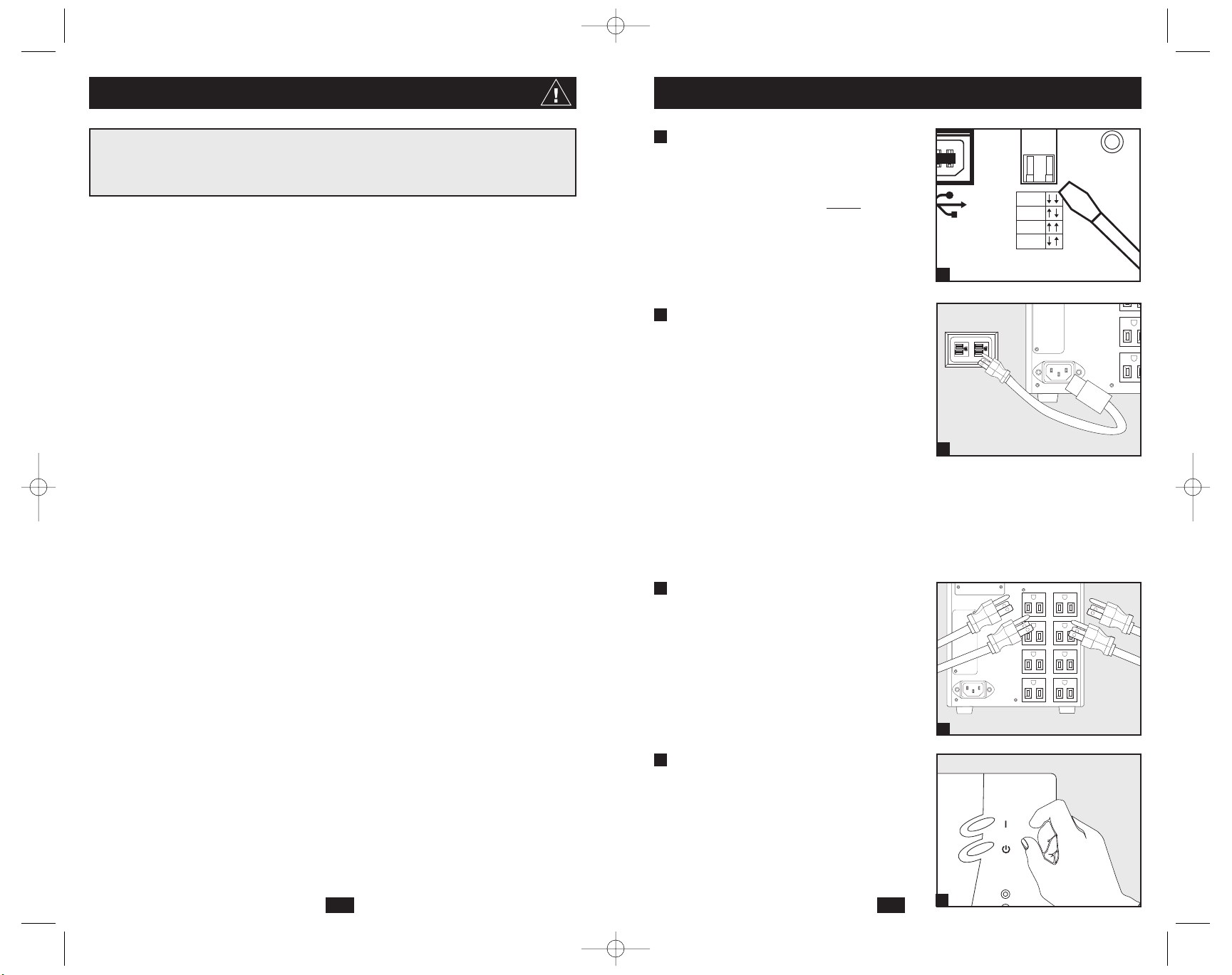
Using a small tool, set the Voltage
Dip Switch to match your input
voltage. (All models are preset to
the 120V setting.)
Note: if the Voltage Dip Switch setting does not match your
input voltage (if it is set above or below the input voltage),
the UPS system will naturally consider the input voltage as
a constant overvoltage or undervoltage condition. The UPS
system will respond accordingly by automatically adjusting
the input voltage to match the Voltage Dip Switch setting.
This will cause constant, unnecessary wear on the UPS system.
Plug one end of the detachable
line cord into your UPS’s AC Input
Receptacle and the other end into
an electrical outlet.
Plug the UPS directly into a properly grounded,
3-wire, 15-amp AC outlet that does not share
a circuit with a heavy electrical load (such as
an air conditioner, refrigerator, etc.).
After plugging your UPS in, check the Site
Wiring Fault LED on its rear panel. If it is lit,
the outlet is improperly wired; unplug the UPS
and have a qualified electrician check the outlet.
Note: Once your UPS is plugged in, it will begin charging
its batteries. If this is the first time you have plugged in your
UPS, or if your UPS has been in storage for a prolonged
period, it will need to charge its batteries for at least 6
hours before it can support connected equipment in the
event of a power failure.
Plug your equipment into your UPS.
Your UPS is designed to support computer
equipment only. You will overload your UPS
if you connect devices with high power
demands such as household appliances or
laser printers to your UPS’s outlets.
Turn your UPS ON:
• Press the “ON/TEST” Switch
• Hold it for several seconds until you
hear a beep
• Release it
Your UPS will begin providing power to its
outlets.
SMART1050SLT shown
2
1
3
4
3
4
SMART1050SLT shown
SMART1050SLT shown
2
SI
W
A
1
SMART1050SLT shown
200308025 Smart1050-1500SLT Owner’s Manual.qxd 11/14/2003 11:40 AM Page 2
F
120V
110V
100V
127V
INPUT
ACCESSORY
INPUT
ON/TEST
OFF
TRIMMING
Page 4
54
Basic Operation
Front Panel Switches
“ON/TEST” Switch: This switch controls four separate UPS functions:
UPS Power On
To turn power on at the outlets, press the “ON/TEST” switch,
hold it for several seconds until you hear a beep, then release it.
UPS Self-Test
When the UPS is in normal operation (the “VOLTAGE OK”
LED is on and the “ON BATTERY” LED is off), press the
“ON/TEST” switch and hold it until you hear a beep. This initiates
a 10-second self-test of the battery. The UPS will shift to battery
power (the “ON BATTERY” LED will illuminate) for ten seconds.
Alarm Silence
To silence the UPS “on-battery” alarm, press the “ON/TEST”
switch and hold it until you hear a beep.
UPS Cold Start
To use your UPS as a stand-alone power source when AC power
is unavailable (i.e. during a blackout), press the “ON/TEST”
switch and hold it until you hear a beep. The UPS will then provide
battery power to its outlets. The “ON BATTERY” LED will be illuminated since your UPS will be operating from battery power.
“OFF” Switch: This switch turns power off at the outlets. Press this
switch, hold it until you hear a beep, then release it. The UPS will
continue charging its batteries and the fan will continue to cool internal
components even after you turn the UPS receptacles off. To turn the
UPS OFF completely, including the charger, disconnect the UPS’s
power cord after pressing the “OFF” switch.
“NORMAL” LED: This green light will be lit when the UPS is providing
AC utility power to connected equipment without needing to alter its
voltage.
“TRIMMING” LED: This yellow light be lit when the UPS is trimming
AC utility power to nominal levels and providing it to connected
equipment. The UPS will click faintly when trimming AC power.
This is a normal, automatic function of your UPS and no action is
required on your part. If your UPS has to trim power frequently, you
may be in a poor power area, and should consider obtaining power
protection for equipment that is not connected to a UPS.
Front Panel Indicator Lights
ON/TEST
ON/TEST
OFF
TRIMMING
NORMAL
BOOSTING
TRIMMING
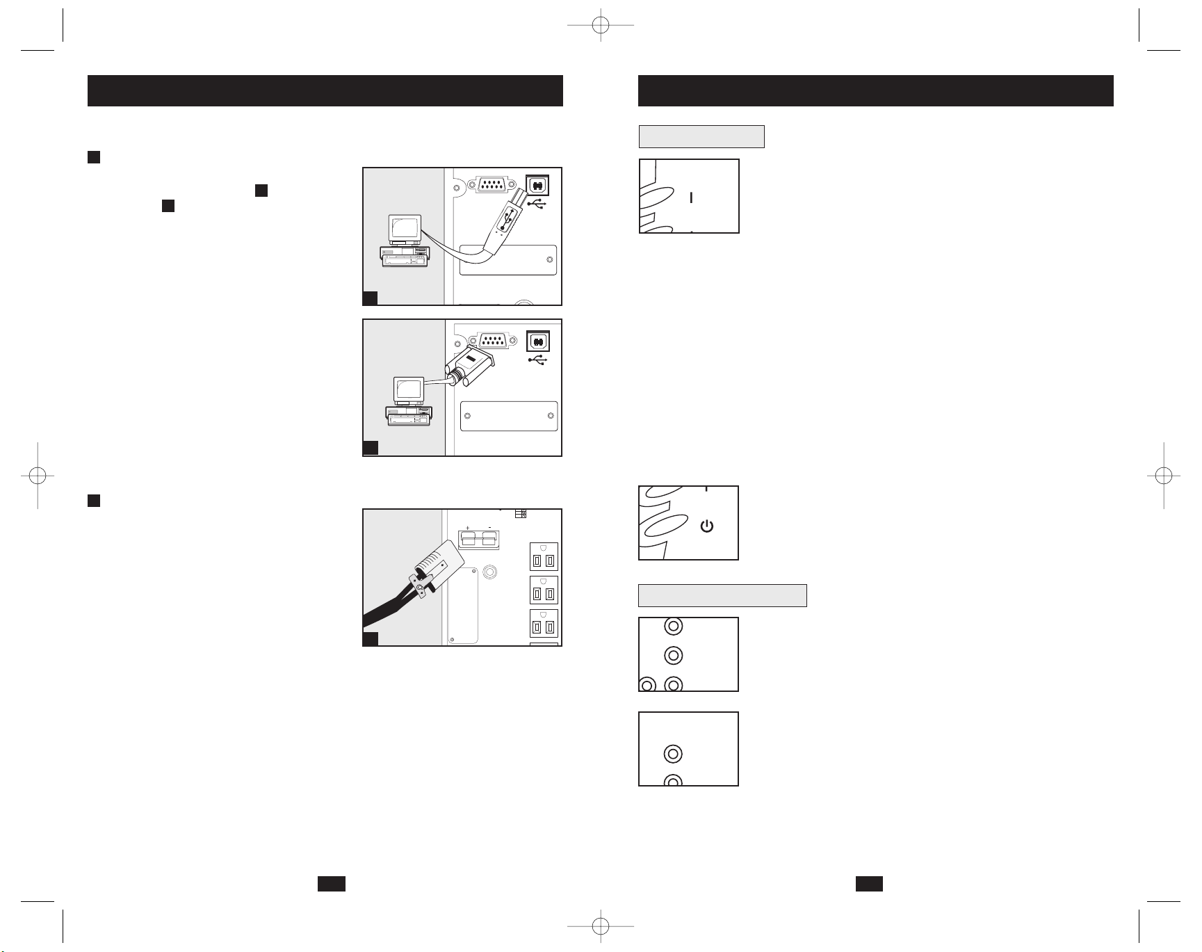
These connections are optional. Your UPS will function properly without these connections.
USB and RS-232 Serial
Communications
Use the included USB cable and/or DB9
serial cable to connect the communication
port on your computer to the communication
port of your UPS. Install on your computer the
Tripp Lite PowerAlert Software appropriate to
your computer’s operating system. Consult your
PowerAlert manual for more information.
External Battery Connection
(select models)
All UPS models come with a robust internal
battery system; select models feature connectors
that accept optional external battery packs
(sold separately from Tripp Lite*) to provide
additional runtime. Adding external batteries
will increase recharge time as well as runtime.
See battery pack owner’s manual for complete
installation instructions. Make sure cables are
fully inserted into their connectors. Small
sparks may result during battery connection; this
is normal. Do not connect or disconnect battery
packs when the UPS is running on battery power.
* See Specifications section for battery packs available for
your specific UPS model.
1a
Optional Installation
1
1a
1b
2
110V
2
SMART1050SLT
shown
SMART1050SLT
shown
SMART1050XL
shown
1b
200308025 Smart1050-1500SLT Owner’s Manual.qxd 11/14/2003 11:40 AM Page 4
ACCESSORY
ACCESSORY
ACCESSORY
SIGNAL
SIGNAL
TVSS
TVSS
100V
127V
Page 5
7
Basic Operation
(continued)
6
Front Panel Indicator Lights
continued
“BOOSTING” LED: This yellow light will be lit when the UPS is
boosting AC utility power to nominal levels and providing it to connected
equipment. The UPS will click faintly when boosting AC power. This
is a normal, automatic function of your UPS and no action is required
on your part. If your UPS has to boost power frequently, you may be
in a poor power area, and should consider obtaining power protection
for equipment that is not connected to a UPS.
“ON BATTERY” LED: This yellow light will be lit when your UPS
is providing your equipment with battery power. The UPS will also
beep every two seconds, unless silenced by the “ON/TEST” Switch.
“BATTERY METER” LEDs: These four green lights show the
approximate charge remaining in the UPS battery. If the battery
charge is very low, the 25% LED will flash and the UPS alarm will
beep every second to warn you that the remaining charge will be
depleted quickly by connected equipment.
“LOAD METER” LED: These four green lights show approximately how much of the UPS’s power capacity is used to support the equipment connected to the outlets.
“OVERLOAD” LED: This red light will be lit when the power draw
of equipment connected to the Battery, Surge and Noise Protected
outlets exceeds your UPS’s power capacity. The UPS alarm will beep
continuously. Immediately disconnect excess equipment from the
outlets until the light and alarm turn off.
“CHECK BATTERY” LED: This red light will be lit if your UPS’s
microprocessor detects a battery fault or if the UPS battery is very
weakly charged. Let your UPS charge for 8 hours, then run another
self-test. If the light stays on, replace the batteries.
SHORT CIRCUIT: If a short circuit occurs, the UPS will stop providing
power to connected equipment and the alarm will sound. If this happens,
eliminate the short circuit.
OVERTEMPERATURE: If the temperature inside the UPS gets too
high, the NORMAL, BOOSTING, TRIMMING and ON BATTERY
LEDs will all light at once and the alarm will sound. If this happens,
check to make sure the UPS’s ventilation grills are unobstructed and
that it is located in a cool, well-ventilated area.
FAULT: If the UPS detects an internal failure, its NORMAL,
BOOSTING and TRIMMING LEDs will light and its alarm will
sound. If this happens, disconnect the UPS and contact Tripp Lite for
service.
NORMAL
BOOSTING
METER
100%
75%
50%
25%
80%
60%
40%
20%
BATTERY
METER
LOAD
OVERLOAD
80%
Basic Operation
(continued)
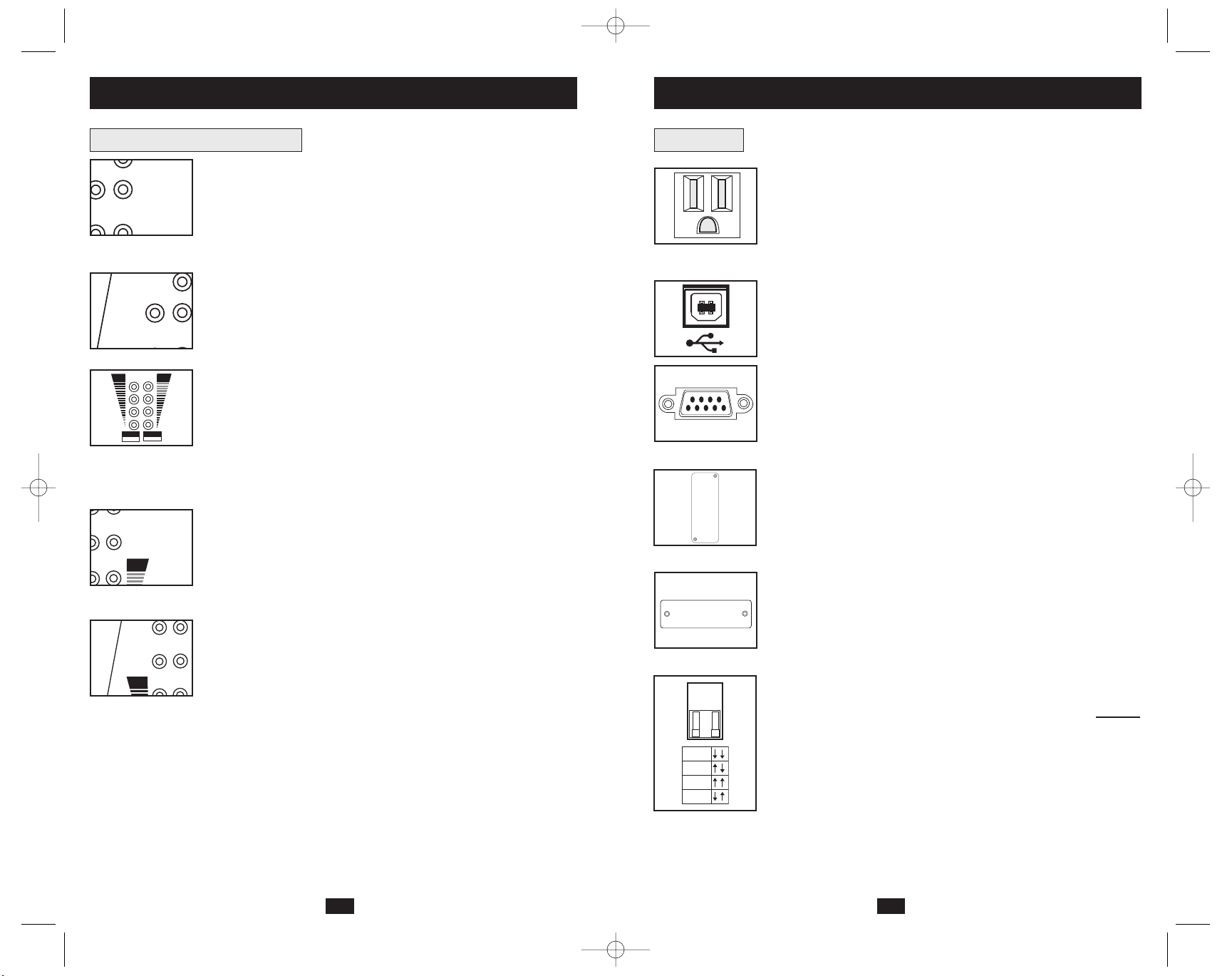
Rear Panel
AC Outlets: These 15-amp receptacles provide your connected equipment with voltage regulated AC output from the AC line during normal operation and from battery power during power failures. These
outlets also protect connected equipment against power surges on the
AC line. Your UPS is designed to support only computer equipment
with battery power. Do not connect equipment with high power
demands (like laser printers) to these outlets.
Communications Ports (USB or RS-232): These ports connect your
UPS to any workstation or server. Use with Tripp Lite's PowerAlert
Software and included cables to enable your computer to automatically
save open files and shut down equipment during a blackout. Also use
PowerAlert Software to monitor a wide variety of AC line power and
UPS operating conditions. Consult your PowerAlert Software manual
or contact Tripp Lite Customer Support for more information. See “USB
and RS-232 Serial Communications” in the “Optional Installation”
section for installation instructions.
Accessory Slot: Remove the small cover panel from this slot to install
optional accessories to remotely monitor and control your UPS. Refer
to your accessory’s manual for installation instructions. Contact Tripp Lite
Customer Support for more information, including a list of available
SNMP, network management and connectivity products.
TVSS Cover Plate (Select Models Only): Remove this plate to
install optional modem/network surge protection modules, available
for purchase by special arrangement with Tripp Lite.
Voltage Dip Switch: Matches the UPS System’s output voltage to the
input voltage available at the wall outlet. See Quick Installation section
for setting instructions. Note: if the Voltage Dip Switch setting does
not
match your input voltage (if it is set above or below the input voltage),
the UPS system will naturally consider the input voltage as a constant
overvoltage or undervoltage condition. The UPS system will respond
accordingly by automatically adjusting the input voltage to match the
Voltage Dip Switch setting. This will cause constant, unnecessary
wear on the UPS system.
ON
BATTERY
B
O
CHECK
BATTERY
ON
BATTERY
200308025 Smart1050-1500SLT Owner’s Manual.qxd 11/14/2003 11:40 AM Page 6
TVSS
120V
110V
100V
127V
Page 6
Input Breaker: Protect your electrical circuit from overcurrent draw
from the UPS load. If this breaker trips, remove some of the load,
then reset it by pressing the breaker in.
External Battery Connector (Select Models Only): Use to connect
Tripp Lite external battery packs for additional runtime. The specifications section of this manual lists the Tripp Lite external battery
packs that are compatible with your model. Refer to instructions
available with the battery pack for complete connection information
and safety warnings.
AC Input Receptacle: Connect one end of the detachable line cord
into this receptacle and the other end into your wall outlet.
“SITE WIRING FAULT” LED: This red LED will be lit if the UPS
detects a problem with the wiring of the AC outlet you connect it to.
If this occurs, have the outlet inspected by a qualified electrician.
Note that while the UPS will detect many common wiring faults,
including a missing ground, reversed polarity and overloaded neutral
circuits, it cannot detect every conceivable wiring problem.
9
Basic Operation
(continued)
8
Rear Panel
continued
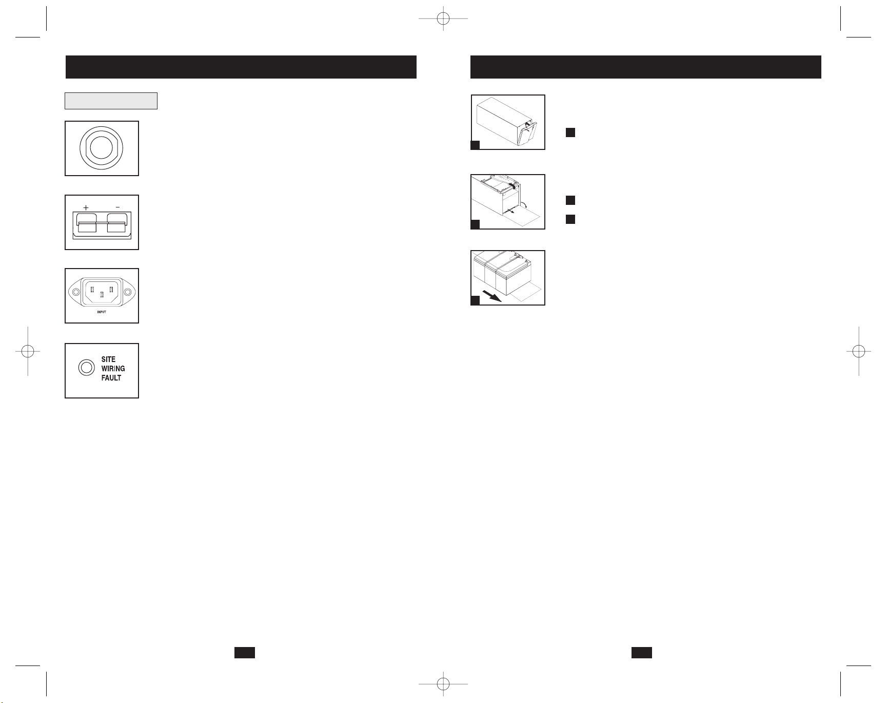
Under normal conditions, the original battery in your UPS will last several
years. Contact Tripp Lite for information about replacement batteries.
Carefully pull the front panel down, out
and away from the UPS.
Be careful not to accidentally disconnect the ribbon cable connecting
the front panel to the rest of the UPS. Place the front panel on top
of the UPS, out of the way.
Unlock and lower the battery door.
Carefully pull the batteries from the UPS.
Replace batteries.
Carefully disconnect the old batteries from the UPS, then connect
the new batteries exactly as the old ones were connected, positive
(red) connectors together and negative (black) terminals together.
Reassemble UPS.
Reverse Steps 1-3, above.
3
2
1
Battery Replacement
1
2
3
200308025 Smart1050-1500SLT Owner’s Manual.qxd 11/14/2003 11:40 AM Page 8
Page 7

11
Specifications
11
Tripp Lite has a policy of continuous improvement. Specifications are subject to change without notice.
SmartPro SLT UPS Systems
Model: SMART1050SLT SMART1500SLT
Series #: AGSM1000DT AGSM1500DT
Input
Nominal Voltage:* 100, 110, 120 or 127 VAC 100, 110, 120 or 127 VAC
Frequency (± 3 Hz.): 60 Hz. 60 Hz.
Recommended Dedicated Electrical Circuit: 15 amp 15 amp
Output
Nominal Voltage:* 100, 110, 120 or 127 VAC 100, 110, 120 or 127 VAC
Frequency (± 3 Hz.): 60 Hz. 60 Hz.
Capacity (VA/Watts)
@ 127 VAC: 1050/670 1500/950
@ 120 VAC: 1050/670 1500/950
@ 110 VAC: 945/603 1350/855
@ 100 VAC: 840/536 1200/760
Waveform (Line and Battery Modes): sine wave sine wave
Maximum Harmonic Distortion (Linear Load/Non-Linear Load): < 3% / < 6% < 3% / < 6%
Battery
Battery Runtime (Half Load/Full Load) Minutes: 20/7 20/8
Battery Recharge Time (to 80% Capacity): 2-4 hours 2-4 hours
Transfer Time: 4-8 milliseconds 4-8 milliseconds
Battery System Voltage: 36 VDC 36 VDC
FCC: Class B Class B
Approvals: UL, cUL, NOM UL, cUL, NOM
SmartPro XL UPS System
Model: SMART750XL
Series #: AGSM751ST
Input
Nominal Voltage:* 100, 110, 120 or 127 VAC
Frequency (± 3 Hz.): 60 Hz.
Recommended Dedicated Electrical Circuit: 15 amp
Output
Nominal Voltage:* 100, 110, 120 or 127 VAC
Frequency (± 3 Hz.): 60 Hz.
Capacity (VA/Watts)
@ 127 VAC: 750/450
@ 120 VAC: 750/450
@ 110 VAC: 675/430
@ 100 VAC: 600/382
Waveform (Line and Battery Modes): sine wave
Maximum Harmonic Distortion (Linear Load/Non-Linear Load): < 3% / < 6%
Battery
Battery Runtime (Half Load/Full Load) Minutes: 33/10+
Battery Recharge Time (to 80% Capacity): 2-4 hours
Transfer Time: 4-8 milliseconds
Battery System Voltage: 36 VDC
FCC: Class B
Approvals: UL, cUL, NOM
* A set of user-selectable Voltage DIP Switches (see Quick Installation section) match the UPS system's output voltage to the input voltage available at the
wall outlet.
+ Battery runtime can be extended with the addition of optional Tripp Lite External Battery Packs (sold separately). SMART750XL models use BP36V27
battery packs. External batteries will increase both the battery runtime and the battery recharge time.
10
Storage
First turn your UPS OFF: press the “OFF” switch to turn power off at the outlets, then disconnect the power cord from the wall outlet. Next, disconnect all equipment to avoid battery drain.
If you plan on storing your UPS for an extended period of time, fully recharge the UPS batteries once every three months by plugging the UPS into a live AC outlet and letting the UPS
charge for 4-6 hours. If you leave your UPS batteries discharged for an extended period of
time, they may suffer permanent loss of capacity.
Service
Before returning your UPS for service, follow these steps:
1. Review the installation and operation instructions in this manual to ensure that the service
problem does not originate from a misreading of the instructions. Also, check that the UPS
System’s circuit breaker(s) are not tripped. This is the most common cause of service
inquiries which can be easily remedied by following the resetting instructions in this manual.
2. If the problem continues, do not contact or return the UPS to the dealer. Instead, call Tripp Lite
at (773) 869-1233. A service technician will ask for the UPS’s model number, serial number
and purchase date and will attempt to correct the problem over the phone.
3. If the problem requires service, the technician will issue you a Returned Material
Authorization (RMA) number, which is required for service. If you require packaging, the
technician can arrange to send you proper packaging. Securely pack the UPS to avoid damage
during shipping. do not use Styrofoam beads for packaging. Any damages (direct, indirect,
special, incidental or consequential) to the UPS incurred during shipment to Tripp Lite or an
authorized Tripp Lite service center is not covered under warranty. UPS Systems shipped to
Tripp Lite or an authorized Tripp Lite service center must have transportation charges prepaid.
Mark the RMA number on the outside of the package. If the UPS System is within the 2-year
warranty period, enclose a copy of your sales receipt. Return the UPS for service using an
insured carrier to the address given to you by the Tripp Lite service technician.
Storage and Service
200308025 Smart1050-1500SLT Owner’s Manual.qxd 11/14/2003 11:40 AM Page 10
Page 8

Manual del propietario
1111 W. 35th Street Chicago, IL 60609 USA • Soporte al cliente: (773) 869-1234 • www.tripplite.com
Instrucciones de seguridad importantes
14
Instalación rápida
15
Instalación opcional
16
Almacenamiento y servicio
22
Especificaciones
23
SmartPro®SLT & SmartPro®XL
Sistemas UPS inteligentes de torre (con ranuras auxiliares)
• Operación interactiva con la línea • Salida de onda sinusoidal
• Opción de tiempo de respaldo extendido (XL)
Modelos SmartPro SLT: SMART1050SLT y SMART1500SLT
Modelo SmartPro XL: SMART750XL
Copyright ©2003 Tripp Lite. Todos los derechos reservados. SmartPro®es una marca comercial registrada de Tripp Lite.
Operación básica
17
English
1
Français
25
Reemplazo de batería
21
12
Specifications
(continued)
FCC RADIO/TV INTERFERENCE NOTICE: Note:This equipment has been tested and found to comply with the limits for a Class
B digital device, pursuant to Part 15 of the FCC Rules. These limits are designed to provide reasonable protection against harmful
interference in a residential installation. This equipment generates, uses and can radiate radio frequency energy, and if not
installed and used in accordance with the instruction manual, may cause interference to radio communications. However, there
is no guarantee that interference will not occur in a particular installation. If this equipment does cause harmful interference to
radio or television reception, which can be determined by turning the equipment off and on, the user is encouraged to try to correct
the interference using one or more of the following measures: reorient or relocate the receiving antenna; increase the separation
between the equipment and the receiver; connect the equipment into an outlet on a circuit different from that which the receiver
is connected; consult the dealer or an experienced radio/television technician for help. The user must use shielded cables and
connectors with this product. Any changes or modifications to this product not expressly approved by the party responsible for
compliance could void the user's authority to operate the equipment. This device complies with part 15 of the FCC rules.
Operation is subject to the following 2 conditions: (1) This device may not cause harmful interference, and (2) This device must
accept any interference received, including interference that may cause undesired operation.
Note on Labeling
Two symbols are used on the label.
V~ : AC Voltage
V : DC Voltage
200308025 Smart1050-1500SLT Owner’s Manual.qxd 11/14/2003 11:40 AM Page 12
Page 9

1514
Advertencias sobre la ubicación del UPS
• Instale su UPS bajo techo, lejos de la humedad, el calor, los contaminantes conductores,
el polvo o la luz solar directa.
• Para un mejor funcionamiento, mantenga la temperatura en el interior entre 32º F y
104º F (0º C y 40º C)
• Deje una cantidad adecuada de espacio alrededor de todos los lados del UPS para una
adecuada ventilación.
Advertencias sobre la conexión del UPS
• Conecte su UPS directamente a una toma de corriente de CA puesta a tierra
apropiadamente. No conecte el UPS a si mismo ya que podría dañarse.
• No modifique el enchufe del UPS ni emplee un adaptador que elimine su conexión a tierra.
• No use cordones de extensión para conectar el UPS a una toma de CA.
• Si el UPS recibe energía de un generador de CA accionado por motor, el generador debe
proporcionar una salida limpia y filtrada de grado computadora.
Advertencias sobre la conexión de equipos
• No utilice un UPS de Tripp Lite para aplicaciones de soporte de vida en las que el
funcionamiento defectuoso o una falla del mismo pudiera causar la falla o una alteración
importante en el funcionamiento de un dispositivo de soporte de vida.
Advertencias sobre la batería
• Su UPS no requiere un mantenimiento de rutina. No abra su UPS por ninguna razón,
salvo para reemplazar la batería. No hay partes en su interior que requieran
mantenimiento por parte del usuario.
• Debido a que las baterías presentan un peligro de choque eléctrico y quemaduras por las
altas corrientes de cortocircuito, tome las precauciones adecuadas. Apague y desconecte
el UPS antes de reemplazar la batería. Use herramientas con mangos aislados y reemplace
las baterías existentes con el mismo número y tipo de baterías nuevas (plomo-ácido selladas)
No abra las baterías. No ponga los terminales de la batería en corto o en puente con
ningún objeto. Tripp Lite ofrece una línea completa de cartuchos de reemplazo de batería
para UPS (R.B.C.) Visite Tripp Lite en la web en www.tripplite.com/support/battery/index.cfm
para localizar la batería de reemplazo específica para su UPS.
• Las baterías del UPS son reciclables. Consulte la reglamentación local para los requisitos
de disposición de desechos; en los EE.UU. llame al 1-800-SAV-LEAD o al 1-800-8-BATTERY (1-800-8-228-8379) o visite www.rbrc.com para obtener información sobre el proceso de reciclaje. No deseche las baterías en un incinerador.
• A menos que su UPS incluya un conector de batería externa, no trate de agregar baterías
externas.
GUARDE ESTAS INSTRUCCIONES
Este manual contiene instrucciones y advertencias que deben seguirse durante la instalación,
la operación y el almacenamiento de todos los UPS de Tripp Lite. La no observancia de
estas advertencias anulará su garantía.
Instrucciones de seguridad importantes Instalación rápida
Con una herramienta pequeña,
ajuste el conmutador DIP de voltaje
para que coincida con su voltaje
de entrada. (Todos los modelos
están ajustados a 120 V en forma
predeterminada)
Nota: Si el ajuste de su conmutador DIP de voltaje no coincide con
el voltaje de entrada (si está fijado por encima o por debajo del voltaje de entrada), el UPS considerará el voltaje de entrada como un
sobrevoltaje o un bajo voltaje. El UPS responderá ajustando
automáticamente el voltaje de entrada para que coincida con el valor
del conmutador DIP, lo que puede causar un desgaste constante e
innecesario en el UPS.
Conecte un extremo del cordón
de alimentación separable en el
receptáculo de entrada de CA de su
UPS y el otro en un tomacorriente
de pared.
Conecte el UPS directamente en un tomacorriente
tripolar de CA de 15 A con el tercer polo correctamente puesto a tierra, y que no comparta el circuito
con una carga eléctrica pesada (como un equipo de
aire acondicionado, un refrigerador, etc.)
Después de conectar su UPS, verifique el estado del
LED Site Wiring Fault (Falla del cableado local) en
el panel posterior. Si está encendido, el tomacorriente
está cableado incorrectamente; desconecte el UPS y
haga revisar el tomacorriente con un electricista.
Nota: En cuanto conecte el UPS, comenzará a cargar sus baterías. Si
es la primera vez que ha conectado su UPS, o si lo ha estado almacenado
por un período prolongado, necesitará cargar sus baterías al menos
por 6 horas antes de que pueda dar soporte a equipo conectado en
caso de una falla de energ
ía.
Conecte sus equipos con el UPS.
Su UPS sólo está diseñado para dar soporte a equipos
de cómputo. Si conecta dispositivos de alto consumo
de energía, como electrodomésticos o impresoras
láser, en las salidas del UPS, lo sobrecargará.
Encienda su UPS
• Presione el interruptor ON/TEST
(Encendido/prueba)
• Manténgalo presionado por varios segundos hasta
que escuche un pitido
• Suéltelo
El UPS comenzará a proporcionar energía a sus
salidas.
SMART1050SLT mostrado
2
1
3
4
3
4
SMART1050SLT mostrado
SMART1050SLT mostrado
2
SI
W
A
1
SMART1050SLT mostrado
200308025 Smart1050-1500SLT Owner’s Manual.qxd 11/14/2003 11:40 AM Page 14
F
120V
110V
100V
127V
INPUT
ACCESSORY
INPUT
ON/TEST
OFF
TRIMMING
Page 10

1716
Estas conexiones son opcionales. Su UPS funcionará correctamente sin ellas.
Comunicaciones USB y serie RS-232
Use el cable USB incluido y/o el cable serie
DB9 para conectar el puerto de comunicaciones de su computadora con el puerto de
comunicaciones de su UPS. Instale en su computadora el software PowerAlert de Tripp Lite
apropiado para su sistema operativo. Consulte su
manual de PowerAlert para mayor información.
Conexión de batería externa
(modelos exclusivos)
Todos los modelos de UPS incluyen un robusto sistema
de batería interna; los modelos exclusivos tienen
conectores que permiten bancos de baterías externas
opcionales (vendidos por separado por Tripp Lite*)
para proporcionar mayor tiempo de respaldo. Al
agregar baterías externas, aumentará el tiempo de
recarga así como el tiempo de respaldo. Consulte el
manual del propietario del banco de baterías para
obtener las instrucciones completas de instalación.
Asegúrese que los cables estén introducidos completamente en sus conectores. Durante la conexión de la
batería se pueden producir pequeñas chispas; esto es
normal. No conecte ni desconecte bancos de baterías
cuando el UPS esté funcionando con energía de las
baterías.
* Vea la sección Especificaciones para conocer los bancos de baterías
disponibles para su modelo de UPS especifico.
1a
Instalación opcional
1
1a
1b
2
110V
2
SMART1050SLT
mostrado
SMART1050SLT
mostrado
SMART1050XL
mostrado
Operación básica
Interruptores del panel frontal
Interruptor “ON/TEST” (Encendido/prueba): Este interruptor controla
cuatro funciones del UPS:
Alimentación de salidas del UPS
Para proporcionar energía a las salidas, presione este interruptor y manténgalo
presionado por varios segundos hasta escuchar un pitido; luego suéltelo.
Auto-prueba del UPS
Durante la operación normal del UPS (el LED “VOLTAGE OK” está
encendido y el LED “ON BATTERY” apagado), presione este interruptor
y manténgalo presionado hasta escuchar un pitido. Esto iniciará una
auto-prueba de la batería durante 10 segundos. El UPS cambiará a
energía de batería (el LED “ON BATTERY” se iluminará) durante diez
segundos.
Silenciar alarma
Para silenciar la alarma “UPS con batería”, presione este interruptor y manténgalo presionado hasta escuchar un pitido.
Arranque del UPS en frío
Para usar su UPS como una fuente de energía independiente cuando no
haya energía de CA de la red (como en una falla del servicio eléctrico),
presione este interruptor y manténgalo presionado hasta escuchar un
pitido. El UPS proporcionará energía de batería a sus salidas. El LED
“ON BATTERY” se iluminará ya que su UPS estará operando con
energía de baterías.
Interruptor “OFF”: Este interruptor corta la alimentación a las salidas del
UPS. Presione este interruptor y manténgalo presionado hasta escuchar un
pitido; luego suéltelo. El UPS seguirá cargando sus baterías y el ventilador
enfriando los componentes internos, incluso después de cortar la alimentación
a las salidas. Para apagar el UPS completamente, incluyendo el cargador,
desconecte su cordón de alimentación después de presionar el interruptor “OFF”.
LED “NORMAL”: Esta luz verde se encenderá cuando el UPS esté suministrando
energía de CA de la red al equipo conectado sin necesidad de modificar su voltaje.
LED “TRIMMING”: Esta luz amarilla se encenderá cuando el UPS esté
reduciendo el voltaje de la red de CA a valores nominales y proporcionándolo
al equipo conectado. El UPS hará clic débilmente al reducir el voltaje de CA.
Esta es una función normal y automática del UPS y no requiere ninguna
acción de su parte. Si el UPS debe reducir el voltaje con frecuencia, es posible
que se encuentre en un área de energía de baja calidad y debería considerar
obtener protección de energía para los equipos no conectados al UPS.
Luces indicadoras del panel frontal
ON/TEST
ON/TEST
OFF
TRIMMING
NORMAL
BOOSTING
TRIMMING
1b
200308025 Smart1050-1500SLT Owner’s Manual.qxd 11/14/2003 11:40 AM Page 16
ACCESSORY
ACCESSORY
ACCESSORY
SIGNAL
SIGNAL
TVSS
TVSS
100V
127V
Page 11

1918
Operación básica
(continúa)
Luces indicadoras del panel frontal
(continúa)
LED “BOOSTING”: Esta luz amarilla se encenderá cuando el UPS esté elevando
el voltaje de CA de la red a valores nominales y proporcionándolo al equipo
conectado. El UPS hará clic débilmente al elevar el voltaje de CA. Esta es una
función normal y automática del UPS y no requiere ninguna acción de su
parte. Si el UPS debe elevar el voltaje con frecuencia, es posible que se
encuentre en un área de energía de baja calidad y debería considerar obtener
protección de energía para los equipos no conectados al UPS.
LED “ON BATTERY”: Esta luz amarilla se encenderá cuando su UPS esté
proporcionando energía de baterías a sus equipos. El UPS también emitirá un pitido
cada dos segundos, a menos que sea silenciado por el interruptor “ON/TEST”.
LEDs “BATTERY METER”: Estas cuatro luces verdes indican la carga
restante aproximada en la batería del UPS. Si la carga de la batería es muy
baja, el LED 25% destellará y la alarma UPS emitirá un pitido cada segundo
para advertirle que la carga restante se agotará rápidamente debido a los
equipos conectados.
LED “LOAD METER”: Estas cuatro luces verdes indican en forma aproximada
cuánto de la capacidad de energía del UPS se está usando para dar soporte a
los equipos conectados a las salidas .
LED “OVERLOAD”: Esta luz roja se encenderá cuando el consumo de los
equipos conectados a las salidas con respaldo de batería y a las salidas protegidas
contra sobretensiones y ruido en la línea, excedan la capacidad de su UPS. La
alarma del UPS emitirá pitidos en forma continua. Desconecte inmediatamente
el exceso de carga de las salidas hasta que la luz y la alarma se apaguen.
LED “CHECK BATTERY”: Esta luz roja se encenderá si el microprocesador
de su UPS detecta una falla en la batería o si ésta tiene muy baja carga. Permita
que su UPS se cargue durante 8 horas y luego ejecute otra auto-prueba. Si la
luz permanece encendida, reemplace las baterías.
CORTOCIRCUITO: Si se produce un cortocircuito, el UPS dejará de proporcionar energía a los equipos conectados y sonará una alarma. En este caso,
debe eliminar el cortocircuito.
SOBRETEMPERATURA: Si la temperatura dentro del UPS se eleva
demasiado, se encenderán los LEDs NORMAL, BOOSTING, TRIMMING y
ON BATTERY al mismo tiempo y sonará una alarma. En este caso, verifique
que el UPS esté ubicado en un lugar fresco y bien ventilado y que sus rejillas
de ventilación no estén obstruidas.
FALLA: Si el UPS detecta una falla interna, se encenderán los LEDs NORMAL, BOOSTING y TRIMMING al mismo tiempo y sonará una alarma. En
este caso, desconecte el UPS y contacte con Tripp Lite para obtener servicio.
NORMAL
BOOSTING
METER
100%
75%
50%
25%
80%
60%
40%
20%
BATTERY
METER
LOAD
OVERLOAD
80%
ON
BATTERY
B
O
CHECK
BATTERY
ON
BATTERY
Operación básica
(continúa)
Panel posterior
Salidas de CA: Estas salidas de 15 A proporcionan voltaje regulado de CA a
sus equipos conectados, tomándolo de la red durante operación normal, y de
baterías durante fallas del suministro de red. Estas salidas también protegen a
los equipos conectados contra sobretensiones transitorias en la línea de CA. Su
UPS solamente está diseñado para dar soporte a equipos de cómputo con
energía de baterías. No conecte equipos de alto consumo de energía (como
impresoras láser) en estas salidas.
Puertos de comunicaciones (USB o RS-232): Estos puertos conectan su UPS
a cualquier estación de trabajo o servidor. Úselos con el software PowerAlert
de Tripp Lite y los cables incluidos para permitir que su computadora guarde
automáticamente los archivos abiertos y apague el equipo durante una falla del
servicio eléctrico. También utilice PowerAlert para vigilar una amplia variedad
de condiciones de operación de la energía de la línea de CA y del UPS.
Consulte su manual de PowerAlert o contacte con el Soporte al cliente de
Tripp Lite para mayor información. Consulte “Comunicaciones USB y serie
RS-232” en la sección “Instalación opcional” para obtener la información
sobre las instrucciones de instalación.
Ranura auxiliar: Retire el pequeño panel de cubierta de esta ranura para
instalar los accesorios opcionales para vigilancia y control de su UPS en forma
remota. Consulte el manual de sus accesorios para obtener las instrucciones de
instalación. Contacte con el Soporte al cliente de Tripp Lite para mayor información,
incluyendo una lista de productos disponibles para SNMP, administración de
red y conectividad.
Placa de cubierta TVSS (Sólo en modelos exclusivos): Retire esta placa para
instalar los módulos opcionales de protección contra sobretensiones para
líneas de módem / red, disponibles mediante una coordinación especial con
Tripp Lite.
Conmutador DIP de voltaje: Hace coincidir el voltaje de salida del UPS con el
voltaje de entrada disponible en el tomacorriente de pared. Consulte la sección
Instalación rápida para obtener las instrucciones de ajuste. Nota: Si el ajuste de
su conmutador DIP de voltaje no coincide con el voltaje de entrada (si está fijado
por encima o por debajo del voltaje de entrada), el UPS considerará el voltaje de
entrada como un sobrevoltaje o un bajo voltaje. El UPS responderá ajustando
automáticamente el voltaje de entrada para que coincida con el valor del conmutador DIP, lo que puede causar un desgaste constante e innecesario en el UPS.
200308025 Smart1050-1500SLT Owner’s Manual.qxd 11/14/2003 11:40 AM Page 18
TVSS
120V
110V
100V
127V
Page 12

2120
Interruptor automático: Protege su circuito eléctrico contra sobrecargas en
la salida del UPS. Si uno de estos interruptores dispara, retire algo de carga y
restablezca el interruptor.
Conector de la batería externa (Sólo en modelos exclusivos): Úselo para
conectar los bancos de baterías externas de Tripp Lite a fin de obtener tiempo
de respaldo adicional. La sección Especificaciones de este manual lista los
bancos de baterías externas de Tripp Lite compatibles con su modelo.
Consulte las instrucciones incluidas con el banco de baterías para obtener
información completa sobre la conexión y las advertencias de seguridad.
Receptáculo de entrada de CA: Conecte un extremo del cordón de alimentación
separable en este receptáculo y el otro en su tomacorriente de pared.
LED “SITE WIRING FAULT” (Falla del cableado local): Este LED rojo se
encenderá si el UPS detecta algún problema con el cableado del tomacorriente
al que se está conectando. En este caso, haga revisar el tomacorriente por un
electricista calificado. Aunque el UPS puede detectar muchas fallas comunes
de cableado, como una tierra ausente, polaridad invertida y circuitos del neutro
sobrecargados, no puede detectar todos los problemas de cableado.
Operación básica
(continúa)
Panel posterior
(continuación)
Bajo circunstancias normales, la batería original de su UPS durará
varios años. Contacte con Tripp Lite para obtener información sobre
las baterías de reemplazo.
Tire cuidadosamente del panel frontal, hacia
afuera y retirándolo del UPS.
Tenga cuidado de no desconectar accidentalmente el cable plano que
conecta el panel frontal con el resto del UPS. Coloque el panel frontal en
la parte superior del UPS.
Desbloquee y baje la puerta de la batería.
Tire con cuidado de las baterías del UPS.
Reemplace las baterías.
Desconecte cuidadosamente las baterías antiguas del UPS y después
conecte las nuevas en la misma forma que las antiguas, es decir, conectores
positivos (rojos) juntos y terminales negativos (negros) juntos.
Vuelva a ensamblar el UPS.
Invierta los pasos 1-3 indicados arriba.
3
2
1
Reemplazo de batería
1
2
3
200308025 Smart1050-1500SLT Owner’s Manual.qxd 11/14/2003 11:40 AM Page 20
Page 13

Especificaciones
23
Tripp Lite tiene una política de mejoramiento continuo. Las especificaciones están sujetas a cambio sin previo aviso.
Sistemas UPS SmartPro SLT
Modelo: SMART1050SLT SMART1500SLT
Serie #: AGSM1000DT AGSM1500DT
Entrada
Voltaje nominal*: 100, 110, 120 or 127 VCA 100, 110, 120 or 127 VCA
Frecuencia (± 3 Hz.): 60 Hz. 60 Hz.
Circuito eléctrico dedicado recomendado: 15 A 15 A
Salida
Voltaje nominal*: 100, 110, 120 or 127 VAC 100, 110, 120 or 127 VAC
Frequency (± 3 Hz.): 60 Hz. 60 Hz.
Capacidad (VA/Vatios)
@ 127 VCA: 1050/670 1500/950
@ 120 VCA: 1050/670 1500/950
@ 110 VCA: 945/603 1350/855
@ 100 VCA: 840/536 1200/760
Forma de onda (Modos de línea y batería): Onda sinusoidal Onda sinusoidal
Distorsión máxima de armónicos (Carga lineal/Carga no lineal): < 3% / < 6% < 3% / < 6%
Batería
Tiempo de respaldo de batería
(Media carga/Carga completa) Minutos: 20/7 20/8
Tiempo de recarga de batería (al 80% de capacidad): 2-4 horas 2-4 horas
Tiempo de transferencia: 4-8 milisegundos 4-8 milisegundos
Voltaje del sistema de baterías: 36 VCC 36 VCC
FCC: Clase B Clase B
Aprobado por: UL, cUL, NOM UL, cUL, NOM
Sistemas UPS SmartPro XL
Modelo: SMART750XL
Serie #: AGSM751ST
Entrada
Voltaje nominal*: 100, 110, 120 or 127 VCA
Frecuencia (± 3 Hz.): 60 Hz.
Circuito eléctrico dedicado recomendado: 15 A
Salida
Voltaje nominal*: 100, 110, 120 or 127 VCA
Frequency (± 3 Hz.): 60 Hz.
Capacidad (VA/Vatios)
@ 127 VCA: 750/450
@ 120 VCA: 750/450
@ 110 VCA: 675/430
@ 100 VCA: 600/382
Forma de onda (Modos de línea y batería): Onda sinusoidal
Distorsión máxima de armónicos (Carga lineal/Carga no lineal): < 3% / < 6%
Batería
Tiempo de respaldo de batería
(Media carga/Carga completa) Minutos: 33/10+
Tiempo de recarga de batería (al 80% de capacidad): 2-4 horas
Tiempo de transferencia: 4-8 milisegundos
Voltaje del sistema de baterías: 36 VCC
FCC: Clase B
Aprobado por: UL, cUL, NOM
* Un conjunto de conmutadores DIP de voltaje seleccionables por el usuario (consulte la sección Instalación rápida) hace coincidir el voltaje de salida del UPS con el voltaje de entrada disponible en el tomacorriente de pared.
+ El tiempo de respaldo de la batería puede extenderse agregando bancos de baterías externas opcionales de Tripp Lite (vendidos por separado) Lo modelo SMART750XL usan los bancos de baterías
BP36V27. Las baterías externas aumentarán los tiempos de respaldo y de recarga de la batería.
22
Almacenamiento
Primero apague su UPS: Presione el interruptor “OFF” para cortar la energía en las salidas y luego
desconecte el cordón de alimentación del tomacorriente. Luego, desconecte todos los equipos para evitar que
se agote la batería. Si planea guardar su UPS por un período prolongado de tiempo, recargue completamente
sus baterías cada tres meses conectándolo en una salida de CA con energía y dejando que se cargue entre
4 y 6 horas. Si deja descargadas las baterías del UPS durante un período prolongado de tiempo, pueden
sufrir una pérdida de capacidad permanente.
Servicio
Antes de enviar su UPS para que le presten servicio, siga los siguientes pasos:
1. Verifique las instrucciones de instalación y operación en este manual para asegurarse que el problema
de servicio no sea causado por una mala interpretación de las instrucciones. Además, verifique que los
interruptores automáticos del UPS no hayan sido disparados. Esta es la causa más común de pedidos de
servicio que pueden ser solucionados fácilmente siguiendo las instrucciones de restablecimiento en este
manual.
2. Si el problema continúa, no contacte con el distribuidor ni devuelva el UPS. En su lugar, llame a Tripp Lite
al (773) 869-1233. Un técnico de servicio le pedirá el modelo, número de serie y fecha de compra del
UPS y tratará de resolver el problema a través del teléfono.
3. Si el problema requiere servicio, el técnico le emitirá un número de Autorización de devolución de mercadería
(RMA), necesario para que le presten servicio. Si requiere embalaje, el técnico puede hacer arreglos para
que le envíen el embalaje adecuado. Empaque el UPS firmemente para evitar daños durante el despacho.
No use camas de Styrofoam para embalaje. Cualquier daño (directo, indirecto, especial, accidental o
resultante) al UPS producido durante el despacho a Tripp Lite o a un centro autorizado de servicio Tripp Lite
no está cubierto por la garantía. Los sistemas UPS enviados a Tripp Lite o a algún centro de servicio
autorizado de Tripp Lite deben tener los cargos de transporte prepagados. Marque el número RMA en
la parte externa del paquete embalado. Si el UPS está dentro del período de garantía de 2 años, adjunte
una copia de su recibo de compra. Devuelva el UPS para servicio a la dirección dada por el técnico de
Tripp Lite utilizando un transportista asegurado.
Almacenamiento y servicio
200308025 Smart1050-1500SLT Owner’s Manual.qxd 11/14/2003 11:40 AM Page 22
Page 14

Guide d'utilisation
1111 W. 35th Street Chicago, IL 60609 É.-U. • Service à la clientèle (773) 869-1234 • www.tripplite.com
Importantes consignes de sécurité
26
Installation rapide
27
Configuration optionnelle
28
Entreposage et entretien/réparations
34
Spécifications
35
SmartPro®SLT et SmartPro®XL
Systèmes de tours ASI intelligentes (équipées de fentes accessoires)
• Fonctionnement en attente active • Puissance sinusoïdale
• Options d'utilisation (XL) étendue
Modèles SmartPro SLT : SMART1050SLT et SMART1500SLT
Modèle SmartPro XL : SMART750XL
Copyright ©2003 Tripp Lite. Tous droits réservés. SmartPro®est une marque de commerce enregistrée de Tripp Lite.
Fonctionnement de base
29
English
1
Español
13
Remplacement des piles
33
2424
Especificaciones
(continúa)
AVISO DE INTERFERENCIA DE RADIO/TV DE LA FCC :
Nota: Este equipo ha sido probado y cumple con los límites para un dispositivo digital Clase B, de acuerdo con la Parte 15 de las Reglas FCC. Estos límites
están diseñados para proporcionar una protección razonable contra interferencia perjudicial en una instalación residencial. Este equipo genera, usa y puede
radiar, energía de radio frecuencia, y si no se instala y usa de acuerdo con el manual de instrucciones, puede causar interferencia a las comunicaciones por
radio. Sin embargo, no hay garantía de que no se producirá interferencia en una instalación en particular. Si este equipo causa interferencia perjudicial a la
recepción de radio o televisión, lo que puede determinarse apagando y encendiendo el equipo, se exhorta al usuario a tratar de corregir la interferencia mediante una o más de las siguientes medidas: reoriente o reubique la antena receptora; aumente la separación entre el equipo y el receptor; conecte el equipo
en una salida en un circuito diferente al circuito donde está conectado el receptor; consulte con el distribuidor o con un técnico experimentado de radio/televisión. El usuario debe utilizar cables y conectores blindados con este producto. Cualquier cambio o modificación a este producto no expresamente autorizado por la parte responsable del cumplimiento de las normas, podría anular la autoridad del usuario para operar el equipo. Este dispositivo cumple con la
Parte 15 de las reglas de la FCC. La operación está sujeta a las siguientes 2 condiciones: (1) Este dispositivo no debe causar ninguna interferencia perjudicial, y (2) Este dispositivo debe aceptar cualquier interferencia recibida, incluyendo la que pueda causar una operación no deseada.
Nota sobre el rotulado
Se usan dos símbolos en la etiqueta.
V~ : Voltaje CA
V : Voltaje CC
200308025 Smart1050-1500SLT Owner’s Manual.qxd 11/14/2003 11:40 AM Page 24
Page 15

2726
Avertissements concernant l'emplacement de l'ASI
• Installez votre ASI à l'intérieur, à l'abri de la chaleur ou de l'humidité excessive, des contaminants
conducteurs, de la poussière ou de l'ensoleillement direct.
• Pour un meilleur rendement, maintenez la température intérieure entre 0º C et 40º C (32º F et 104º F).
• Laissez suffisamment d'espace de chaque côté de l'ASI pour permettre une ventilation adéquate.
Avertissements concernant le branchement de l'ASI
• Branchez votre ASI directement à une prise de courant correctement mise à la terre. Ne branchez pas
l'ASI sur lui-même, vous pourriez l'endommager.
• Ne modifiez pas la prise de l'ASI et n'utilisez jamais d'adaptateur qui éliminerait la prise de terre de
l'ASI.
• N'utilisez pas de rallonge électrique pour brancher l'ASI à la prise de courant.
• Si l'ASI reçoit son alimentation d'un moteur-générateur à courant alternatif, ce dernier doit fournir
une énergie de qualité informatique propre et filtrée.
Avertissements concernant le branchement d'équipement
• N'utilisez pas les systèmes ASI Tripp Lite avec des appareils de maintien des fonctions vitales sur
lesquels une défectuosité ou une défaillance du système ASI Tripp Lite pourrait causer la défaillance
ou une altération significative du rendement d'un tel appareil de maintien des fonctions vitales.
Avertissements concernant les piles
• Votre ASI ne requiert pas d'entretien régulier. N'ouvrez jamais votre ASI sauf pour le remplacement
des piles. Aucune pièce se trouvant à l'intérieur ne peut être réparée ou entretenue par l'utilisateur.
• Parce que les piles peuvent causer des chocs électriques et des brûlures en raison du courant de
court-circuit élevé, observez les mesures de précaution qui s'imposent. Débranchez et éteignez l'ASI
avant d'effectuer le remplacement des piles. Utilisez des outils dont les poignées sont isolées et
remplacez les piles avec d'autres piles de même type (piles au plomb étanches) et portant le même
numéro. N'ouvrez pas les piles. Ne court-circuitez ni ne dérivez jamais les bornes des piles avec
quelque objet que ce soit. Tripp Lite propose une gamme complète de cartouches de piles de remplacement (R.B.C.) pour le système ASI. Visitez Tripp Lite sur Internet à l'adresse
www.tripplite.com/support/battery/index.cfm afin de trouver les piles de remplacement qui
conviennent à votre ASI.
• Les piles ASI sont recyclables. Consultez la réglementation locale concernant la mise au rebut ou, aux
États-Unis seulement, téléphonez au 1-800-SAV-LEAD ou au 1-800-8-BATTERY (1-800-8-228-8379),
ou visitez le site www.rbrc.com pour obtenir des informations sur la récupération. Ne jetez jamais de
piles au feu.
• À moins que votre système ASI ne comprenne une connexion de pile externe, n'essayez pas d'ajouter
de piles externes.
CONSERVEZ CES CONSIGNES
Ce guide contient des consignes et avertissements qui doivent être respectés lors de l'installation, de l'utilisation et du rangement de tous les systèmes ASI Tripp Lite. Ne pas
respecter ces avertissements annulera votre garantie.
Importantes consignes de sécurité Installation rapide
À l'aide d'un petit outil, réglez le
commutateur DIP de tension pour
qu'il corresponde à votre tension
d'entrée. (Tous les modèles sont
préréglés à 120 V.)
Remarque : si le réglage du commutateur DIP de tension ne correspond pas
à votre tension d'entrée (s'il est réglé à une tension d'entrée
supérieure ou inférieure), le système ASI interprétera la tension de
sortie comme étant continuellement en surtension ou en sous-tension. Le
système ASI répondra en conséquence et réglera automatiquement la tension
d'entrée pour que celle-ci corresponde au réglage du commutateur
DIP de tension. Ceci provoquerait une usure continue et inutile et du
système ASI.
Branchez une extrémité du cordon
détachable dans l'entrée alternative
de votre ASI et l'autre extrémité
dans une prise de courant.
Branchez directement l'ASI à une prise de courant
correctement mise à la terre à 3 fiches de 15
ampères, dont le circuit n'est pas partagé avec une
charge électrique élevée (par exemple, une unité de
climatisation, un réfrigérateur, etc.).
Une fois l'ASI branché, vérifiez la DEL Site Wiring
Fault située sur le panneau arrière. Si celle-ci est
allumée, la prise est inadéquatement câblée;
débranchez donc l'ASI et faites vérifier la prise de
courant par un électricien qualifié.
Remarque : Une fois votre ASI branché, celui-ci commencera à
charger ses piles. Si c'est la première fois que votre ASI est branché,
ou si votre ASI a été rangé pendant une longue période, il devra
charger ses piles pendant au moins 6 heures avant d'être en mesure
de soutenir l'équipement en cas de panne de courant.
Branchez votre équipement dans l'ASI.
Votre ASI est conçu uniquement pour soutenir de
l'équipement informatique. Vous surchargerez votre
ASI si vous y branchez des appareils qui requièrent
beaucoup d'électricité comme les appareils
ménagers et les imprimantes au laser.
Mettez votre ASI en position ON.
• Appuyez sur le bouton "ON/TEST"
• Maintenez-le enfoncé jusqu'à ce que vous
entendiez un bip
• Relâchez-le
Votre ASI commencera à alimenter ses prises.
SMART1050SLT illustré
2
1
3
4
3
4
SMART1050SLT illustré
SMART1050SLT illustré
2
SI
W
A
1
SMART1050SLT illustré
200308025 Smart1050-1500SLT Owner’s Manual.qxd 11/14/2003 11:40 AM Page 26
F
120V
110V
100V
127V
INPUT
ACCESSORY
INPUT
ON/TEST
OFF
TRIMMING
Page 16

2928
Ces branchements sont optionnels. Votre ASI fonctionnera correctement sans ces branchements.
Ports de communication USB
et série RS-232
Utilisez le câble USB inclus et/ou le câble de port
série DB9 pour relier le port de communication de
votre ordinateur à celui de votre ASI. Installez sur
votre ordinateur le logiciel Tripp Lite PowerAlert qui
convient au système d'exploitation que vous utilisez.
Consultez votre guide PowerAlert pour plus de renseignements.
Branchement d'une pile externe
(sur certains modèles)
Tous les modèles d'ASI sont équipés d'un système
robuste de piles internes alors que certains modèles
sont dotés de connecteurs permettant de brancher des
bloc-piles externes optionnels (vendus séparément*)
permettant d'ajouter du temps d'exécution. L'ajout de
piles externes augmentera le temps de recharge aussi bien
que le temps d'exécution. Consultez le guide d'utilisation
du bloc-piles pour connaître les directives d'installation
détaillées. Veillez à ce que les câbles soient complètement insérés dans leurs connecteurs. De petites
étincelles peuvent survenir lors du branchement de la
pile; c'est tout à fait normal. Ne branchez ni ne
débranchez jamais les bloc-piles pendant que l'ASI
fonctionne grâce à l'alimentation par pile.
* Consultez la section des spécifications pour savoir quels bloc-piles
peuvent être utilisés avec votre modèle d'ASI .
1a
Configuration optionnelle
1
1a
1b
2
110V
2
SMART1050SLT
illustré
SMART1050SLT
illustré
SMART1050XL
illustré
Fonctionnement de base
Boutons du panneau avant
Bouton “ON/TEST” : Ce bouton commande quatre fonctions distinctes de
votre ASI :
Mise sous tension de l'ASI
Pour mettre sous tension les prises de l'ASI, appuyez sur le bouton,
maintenez-le enfoncé pendant plusieurs secondes jusqu'à ce que vous
entendiez un bip puis relâchez-le.
Auto-diagnostic de l'ASI
Lorsque l'ASI est en mode de fonctionnement normal (le témoin
« VOLTAGE OK » est allumée et le témoin « ON BATTERY » est
éteint), appuyez sur ce bouton jusqu'à ce que vous entendiez un bip. Ceci
amorce un auto-diagnostic de 10 secondes de la pile. L'ASI sera alors
alimenté par pile (le témoin « ON BATTERY » est allumé) pendant 10
secondes.
Arrêt d'alarme
Pour désactiver l'alarme « on-battery » de l'ASI, appuyez sur ce bouton
jusqu'à ce que vous entendiez un bip.
Mise en marche à froid de l'ASI
Pour utiliser votre ASI comme source d'énergie autonome lorsque l'électricité n'est pas disponible (c'est-à-dire en cas de panne), appuyez sur ce
bouton et maintenez-le enfoncé jusqu'à ce que vous entendiez un bip.
Votre ASI alimentera ses prises en énergie. le témoin « ON BATTERY
» sera allumé puisque votre ASI est alimenté par piles.
Bouton “OFF” : Ce bouton met les prises hors tension. Appuyez sur le bouton,
maintenez-le enfoncé jusqu'à ce que vous entendiez un bip puis relâchez-le.
L'ASI continuera de charger ses piles et le ventilateur continuera de refroidir
les composants internes même lorsque vous aurez mises hors tensions les prises
de l'ASI. Pour désactiver complètement l'ASI, y compris le chargeur,
débranchez le cordon d'alimentation de la prise de courant après avoir appuyé
sur le bouton “OFF”.
TÉMOIN “NORMAL” : Le voyant vert s'allume lorsque l'ASI alimente en
électricité l'équipement branché sans avoir besoin de modifier sa tension.
TÉMOIN “TRIMMING” : Le voyant jaune s'allume lorsque l'ASI ajuste
l'alimentation en électricité à un niveau nominal et la fournit à l'équipement
branché. L'ASI cliquettera légèrement pendant l'ajustement de l'alimentation
en électricité. C'est une fonction normale et automatique de votre ASI; vous
n'avez pas à faire quoi que ce soit. Si votre ASI doit ajuster souvent l'alimentation, il se peut que vous soyez dans une zone dont l'alimentation est faible.
Si c'est le cas, vous devriez penser à vous doter d'une protection d'alimentation
pour l'équipement qui n'est pas branché à un ASI.
Voyants du panneau avant
ON/TEST
ON/TEST
OFF
TRIMMING
NORMAL
BOOSTING
TRIMMING
1b
200308025 Smart1050-1500SLT Owner’s Manual.qxd 11/14/2003 11:40 AM Page 28
ACCESSORY
ACCESSORY
SIGNAL
SIGNAL
TVSS
TVSS
100V
127V
ACCESSORY
Page 17

3130
Fonctionnement de base
(suite)
Voyants du panneau avant suite
TÉMOIN “BOOSTING” : Ce voyant jaune s'allume lorsque l'ASI augmente
l'alimentation en électricité à un niveau nominal et la fournit à l'équipement
branché. L'ASI cliquettera légèrement pendant l'augmentation de l'alimentation
en électricité. C'est une fonction normale et automatique de votre ASI; vous
n'avez pas à faire quoi que ce soit. Si votre ASI doit souvent augmenter l'alimentation, il se peut que vous soyez dans une zone dont l'alimentation est faible.
Si c'est le cas, vous devriez penser à vous doter d'une protection d'alimentation pour l'équipement qui n'est pas branché à un ASI.
TÉMOIN “ON BATTERY” : Ce voyant jaune s'allume lorsque votre ASI
fournit l'énergie des piles à votre équipement. L'ASI émettra aussi un bip
toutes les deux secondes à moins que l'alarme ait été désactivée à l'aide du
bouton “ON/TEST”.
TÉMOIN “BATTERY METER” : Ces quatre voyants verts montrent le
niveau approximatif de charge de la pile de l'ASI. Si la charge de la pile est
très faible, la TÉMOIN 25% clignotera et l'alarme de l'ASI émettra un bip
toutes les secondes pour vous avertir que la charge restante sera rapidement
affaiblie par l'équipement branché.
TÉMOIN “LOAD METER” : Ces quatre voyants verts montrent la quantité
approximative d'énergie de l'ASI utilisée pour soutenir l'équipement branché
aux prises.
TÉMOIN “OVERLOAD” : Ce voyant rouge s'allume lorsque l'énergie
nécessaire à l'équipement branché est supérieure à la capacité énergétique des
prises alimentées par pile et protégées contre les surtensions et le bruit de votre
ASI. L'alarme de l'ASI émettra un bip sans arrêt. Débranchez immédiatement
l'équipement en surplus des prises jusqu'à ce que le voyant et l'alarme
s'éteignent.
TÉMOIN “CHECK BATTERY” : Ce voyant rouge s'allume lorsque le
microprocesseur de votre ASI détecte une défaillance de la pile ou si la pile de
votre ASI est très faiblement chargée. Laissez votre ASI charger pendant 8
heures puis effectuez de nouveau l'auto-diagnostic. Si le voyant demeure
allumé, remplacez les piles.
COURT-CIRCUIT : Si un court-circuit se produit, l'ASI cessera d'alimenter
l'équipement branché et l'alarme émettra un son. Si cela se produit, éliminez
le court-circuit.
SURCHAUFFE : Si la température à l'intérieur de l'ASI devient trop élevée,
les TÉMOINS « NORMAL », « BOOSTING », « TRIMMING » et « ON
BATTERY » s'allumeront tous simultanément et l'alarme retentira. Si cela se
produit, vérifiez que les grilles d'aération de l'ASI ne sont pas obstruées et que
l'unité est située dans un endroit frais et bien aéré.
ANOMALIE : Si l'ASI détecte une défaillance interne, les TÉMOINS «
NORMAL », « BOOSTING » et « TRIMMING » s'allumeront tous simultanément et l'alarme retentira. Si ceci se produit, débranchez l'ASI et contactez
la division service de Tripp Lite.
NORMAL
BOOSTING
METER
100%
75%
50%
25%
80%
60%
40%
20%
BATTERY
METER
LOAD
OVERLOAD
80%
ON
BATTERY
B
O
CHECK
BATTERY
ON
BATTERY
Fonctionnement de base
(suite)
Panneau arrière
Prises de courant : Ces prises de 15 ampères alimentent l'équipement connecté
grâce à une sortie alternative à régulation de tension à partir de la ligne c.a.
pendant le fonctionnement normal et grâce aux piles en cas de panne de
courant. Ces prises protègent aussi l'équipement branché contre les surtensions
sur la ligne c.a. Votre ASI est conçu uniquement pour alimenter à pile de
l'équipement informatique. N'y branchez pas d'équipement qui requiert beaucoup
d'électricité (comme les imprimantes au laser).
Ports de communication (USB ou RS-232) : Ces ports connectent votre UPS
à n'importe quelle station de travail ou serveur. Les utiliser avec le logiciel
PowerAlert de Tripp Lite et les câbles inclus pour permettre à votre ordinateur
de sauvegarder automatiquement les fichiers ouverts et de mettre votre
équipement hors tension pendant une panne. Utiliser aussi le logiciel
PowerAlert pour surveiller une grande variété de conditions de fonctionnement du secteur et de l'UPS. Consulter votre manuel du logiciel PowerAlert
ou communiquer avec le service à la clientèle de Tripp Lite pour plus de renseignements. Voir “Communications de série USB et RS-232” dans la section
“Installation en option” pour les directives d'installation.
Fente pour accessoire : Retirez le petit panneau protecteur sur la fente pour
installer des accessoires optionnels permettant la commande et la surveillance
à distance de votre ASI. Consultez le guide de l'accessoire choisi pour connaître
les directives d'installation. Contactez le soutien à la clientèle de Tripp Lite
pour plus de renseignements, ou pour obtenir la liste des produits SNMP, de
gestion réseau et de connectivité disponibles.
Plaque couvercle TVSS (sur certains modèles seulement) : Retirez cette
plaque pour installer de l'équipement optionnel tel un modem ou un module de
protection contre les surtensions réseau, disponible à l'achat par arrangement
spécial avec Tripp Lite.
Commutateur DIP de tension : Agence la tension de sortie du système ASI
à la tension d'entrée disponible dans la prise de courant. Consultez la section
Installation rapide pour connaître les instructions de réglage. Remarque : si le
réglage du commutateur DIP de tension ne corr
espond pas à votre tension
d'entrée (s'il est réglé à une tension d'entrée plus supérieure ou inférieure), le
système ASI interprétera la tension de sortie comme étant continuellement en
surtension ou en sous-tension. Le système ASI répondra en conséquence et
réglera automatiquement la tension d'entrée pour que celle-ci corresponde au
réglage du commutateur DIP de tension. Ceci provoquera une usure continue
et inutile du système ASI.
200308025 Smart1050-1500SLT Owner’s Manual.qxd 11/14/2003 11:40 AM Page 30
TVSS
120V
110V
100V
127V
Page 18

3332
Disjoncteur d'entrée : Protège votre circuit électrique d'une surintensité qui
pourrait être causée par la charge de l'ASI. Si le disjoncteur se déclenche,
débranchez certains appareils/équipement puis réinitialisez en appuyant sur le
disjoncteur.
Connecteur de pile externe (sur certains modèles seulement) : Utilisez-le
pour brancher des bloc-piles externes Tripp Lite et ainsi obtenir du temps d'exploitation supplémentaire. La section des spécifications de ce guide répertorie
les bloc-piles externes Tripp Lite compatibles avec votre modèle. Consultez
les instructions fournies avec le bloc-piles pour obtenir toutes les informations
au sujet du branchement et les avertissement concernant la sécurité.
Entrée alternative : Branchez une extrémité du cordon d'alimentation détachable
dans l'entrée alternative et l'autre extrémité dans la prise de courant au mur.
TÉMOIN “SITE WIRING FAULT” : Ce témoin rouge s'allume si l'ASI
détecte un problème avec le câblage de la prise de courant à laquelle il est branché.
Si ceci se produit, faites inspecter la prise de courant par un électricien qualifié.
Veuillez noter que même si l'ASI détecte la plupart des défaillances de
câblage, dont une mise à la terre manquante, une polarité inversée et des circuits
neutres surchargés, il ne peut détecter tous les problèmes de câblage possibles.
Fonctionnement de base
(suite)
Panneau arrière
suite
Sous des conditions normales de fonctionnement, la pile originale de votre ASI
durera plusieurs années. Contactez Tripp Lite pour obtenir plus d'information
à propos du remplacement des piles.
Tirez délicatement le panneau avant vers le bas
et éloignez-le de l'ASI.
Veillez à ne pas débrancher accidentellement le câble plat qui relie le panneau
avant à l'ASI. Déposez le panneau avant sur l'ASI pour qu'il ne vous
encombre pas.
Déverrouillez et abaissez le couvercle du
compartiment des piles.
Retirez délicatement les piles de l'ASI.
Remplacez les piles.
Débranchez délicatement les anciennes piles de l'ASI puis branchez les
nouvelles piles de la même manière que l'étaient les anciennes, c'est-à-dire
les bornes positives (rouges) ensemble et les bornes négatives (noires) ensemble.
Réassemblez l'ASI.
Reprenez les étapes ci-dessus de 3 à 1.
3
2
1
Remplacement des piles
1
2
3
200308025 Smart1050-1500SLT Owner’s Manual.qxd 11/14/2003 11:40 AM Page 32
Page 19

3534
Spécifications
La politique de Tripp Lite compte en est une d'amélioration continue. Ces spécifications sont sujettes à changement sans préavis.
Systèmes ASI SmartPro SLT
Modèle : SMART1050SLT SMART1500SLT
No série : AGSM1000DT AGSM1500DT
Données
Tension nominale d'entrée :* 100, 110, 120 or 127 VAC 100, 110, 120 or 127 VAC
Fréquence (± 3 Hz.): 60 Hz. 60 Hz.
Circuit électrique spécialisé recommandé : 15 ampères 15 ampères
Capacité sortie
Tension nominale d'entrée :* 100, 110, 120 or 127 VAC 100, 110, 120 or 127 VAC
Fréquence (± 3 Hz.): 60 Hz. 60 Hz.
Capacité (VA/Watts)
@ 127 VAC: 1050/670 1500/950
@ 120 VAC: 1050/670 1500/950
@ 110 VAC: 945/603 1350/855
@ 100 VAC: 840/536 1200/760
Forme d'onde (modes trait et pile) : sinusoïdale sinusoïdale
Distorsion harmonique maximale
(charge linéaire/charge non-linéaire) : < 3% / < 6% < 3% / < 6%
Piles
Temps d'exploitation des piles
(demi charge/pleine charge) minutes : 20/7 20/8
Temps de recharge des piles (à une capacité de 80 %) : 2-4 heures 2-4 heures
Durée de transfert : 4-8 millisecondes 4-8 millisecondes
Tension du système de piles : 36 VDC 36 VDC
CFC: Classe B Classe B
Homologations: UL, cUL, NOM UL, cUL, NOM
Systèmes ASI SmartPro XL
Modèle : SMART750XL
No série : AGSM751ST
Données
Tension nominale d'entrée :* 100, 110, 120 or 127 VAC
Fréquence (± 3 Hz.): 60 Hz.
Circuit électrique spécialisé recommandé : 15 ampères
Capacité sortie
Tension nominale d'entrée :* 100, 110, 120 or 127 VAC
Fréquence (± 3 Hz.): 60 Hz.
Capacité (VA/Watts)
@ 127 VAC: 750/450
@ 120 VAC: 750/450
@ 110 VAC: 675/430
@ 100 VAC: 600/382
Forme d'onde (modes trait et pile) : sinusoïdale
Distorsion harmonique maximale
(charge linéaire/charge non-linéaire) : < 3% / < 6%
Piles
Temps d'exploitation des piles
(demi charge/pleine charge) minutes : 33/10+
Temps de recharge des piles (à une capacité de 80 %) : 2-4 heures
Durée de transfert : 4-8 millisecondes
Tension du système de piles : 36 VDC
CFC: Classe B
Homologations : UL, cUL, NOM
* Un ensemble de commutateurs DIP de tension sélectionnés par l'utilisateur (consultez la section Installation rapide) agence la tension de sortie du système ASI à la tension d'entrée disponible à la prise de courant au mur.
+ Le temps d'utilisation des piles peut être allongé grâce à l'ajout de bloc-piles externes Tripp Lite (vendus séparément). Le modèle SMART750XL utilisent les bloc-piles
BP36V27. Les piles externes augmenteront à la fois le temps d'utilisation et le temps de recharge des piles.
Entreposage
Mettez d'abord votre ASI hors tension : appuyez sur le bouton “OFF” pour mettre les prises hors tension,
puis débranchez le cordon d'alimentation de la prise de courant. Ensuite, débranchez tous les
appareils/équipements pour éviter de décharger les piles. Si vous pensez entreposer votre ASI pendant une
longue période, rechargez complètement les piles de l'ASI tous les trois mois en le branchant dans une prise
de courant sous tension et en le laissant charger de quatre à six heures. Si vous laissez les piles de l'ASI
déchargées pendant une longue période, elles risquent de souffrir d'une perte de capacité permanente.
Entretien/réparations
Avant d'envoyer votre UPS pour réparations, suivre ces étapes ;
1. Relire les directives d'installation et de fonctionnement dans ce manuel pour vous assurer que le problème n'a pas pour origine une mauvaise lecture des directives. Vérifier également que les disjoncteurs du
circuit du système UPS n'ont pas sauté. C'est la cause la plus courante des demandes de service; on peut y
remédier facilement en suivant les directives de remise en marche dans ce manuel.
2. Si le problème persiste, ne pas communiquer ou renvoyer l'UPS au vendeur. À la place, appeler Tripp Lite
au (773) 869-1233. Un technicien des réparations vous demandera le numéro de modèle de l'UPS, son
numéro de série et sa date d'achat et essaiera de régler le problème au téléphone.
3. Si le problème nécessite une réparation, le technicien vous émettra un numéro d'autorisation de retour
de matériel (RMA) qui est exigée pour une réparation. Si vous avez besoin d'un emballage, le technicien peut vous faire envoyer un emballage approprié. Emballer soigneusement l'UPS pour éviter des dommages pendant l'expédition. Ne pas utiliser de billes de styrofoam pour emballer. Tout dommage (direct,
indirect, spécial, accidentel ou fortuit) arrivé à l'UPS pendant le transport à Trip Lite ou à un centre de service autorisé Tripp Lite est exclu de la garantie. Les frais de transport des systèmes UPS envoyés à Trip Lite ou
à un centre de service autorisé Tripp Lite doivent être prépayés. Inscrire le numéro de RMA sur le paquet.
Si l'UPS est encore couvert par la garantie de deux ans, joindre une copie de votre facture d'achat. Renvoyer
l'UPS pour réparation par un transporteur assuré à l'adresse que vous a donnée le technicien de service de Tripp
Lite.
Entreposage et entretien/réparations
200308025 Smart1050-1500SLT Owner’s Manual.qxd 11/14/2003 11:40 AM Page 34
Page 20

200308025 93-2178
1111 W. 35th Street Chicago, IL 60609 USA
Customer Support: (773) 869-1234
Spécifications
(suite)
AVIS DU FCC CONCERNANT LES INTERFÉRENCES RADIO/TÉLÉ : (POUR LES MODÈLES DE CLASSE B)
Note : Cet équipement a été testé et trouvé compatible avec les limites d'un dispositif numérique de Classe B, conformément à la partie 15 des règlements
du FCC. Ces limites ont été prévues pour assurer une protection raisonnable contre les interférences nuisibles dans un environnement résidentiel. Cet
équipement génère, utilise et peut émettre des fréquences radio et, s'il n'est pas installé et utilisé conformément aux directives, peut provoquer des interférences dans les communications radio. Cependant, il n'existe aucune garantie que des interférences ne se produiront pas dans une installation particulière.
Si cet équipement produit une interférence nuisible à la réception de la radio ou de la télévision, ce qui peut être déterminé en éteignant et en allumant
l'équipement, on recommande à l'utilisateur d'essayer de corriger la situation en appliquant l'une ou plusieurs des mesures suivantes : Réorienter ou déplacer l'antenne de réception; augmenter la distance entre l'équipement et le récepteur, brancher l'équipement dans une prise d'un circuit différent que celui auquel
le récepteur est branché, consulter le vendeur ou un technicien radio/télé expérimenté pour assistance. L'utilisateur doit utiliser des câbles et des connecteurs
blindés avec ce produit. Tous changements ou modifications à ce produit non expressément approuvés par la partie responsable de sa conformité pourra
annuler le droit d'utiliser l'équipement à l'utilisateur. Ce dispositif est conforme à la partie 15 des règlements du FCC. Son opération est sujette aux deux obligations suivantes : (1) Ce dispositif ne doit causer aucune interférence nuisible et (2) Ce dispositif doit être en mesure de recevoir toute interférence, y compris des interférences pouvant provoquer un fonctionnement non désiré.
Note sur l'étiquetage
Deux symboles sont utilisés sur l'étiquette.
V~ : Voltage c.a.
V : Voltage c.c.
200308025 Smart1050-1500SLT Owner’s Manual.qxd 11/14/2003 11:40 AM Page 36
 Loading...