

Page 1

1111 W. 35th Street • Chicago, IL 60609 USA
Customer Support: (773) 869-1234 • Application Services: (773) 869-1236 • www.tripplite.com
Copyright ©2004 Tripp Lite. All rights reserved.
Important Safety Warnings
Mounting
Connection
Features
Operation
Storage, Service, Warranty and Insurance
Specifications
Español/Français/Русский
2
3
5
10
21
24
25
27/53/79
Optional Connection
17
Power ON/OFF
18
Manual Bypass Operation
20
Owner’s Manual
SmartOnline™Single-Phase 5kVA, 6kVA & 10kVA
Intelligent True On-Line UPS Systems (Rackmount/Tower)
For all UPS system modules (power module, transformer module and battery module) sold either separately or
combined. Select UPS system modules may include separate instruction or warning sheets which should be used
in conjunction with this manual.
Warranty
Registration
Register on-line today for a
chance to win a FREE Tripp Lite
product! www.tripplite.com/warranty
Page 2

2
Important Safety Warnings
SAVE THESE INSTRUCTIONS. This manual contains important instructions and warnings that should be followed during the installation and
maintenance of all Tripp Lite SmartOnline Rackmount/Tower UPS Systems and their batteries.
UPS Location Warnings
• Install your UPS indoors, away from excess moisture or heat, direct sunlight, dust and conductive contaminants.
• Install your UPS in a structurally sound area. Your UPS is extremely heavy; take care when moving and lifting the unit.
• Only operate your UPS at indoor temperatures between 32° F and 104° F (between 0° C and 40° C). For best results, keep indoor
temperatures between 62° F and 84° F (between 17° C and 29° C).
• Leave adequate space around all sides of the UPS for proper ventilation.
• Do not install the UPS near magnetic storage media, as this may result in data corruption.
UPS Connection Warnings
• The power supply for this unit must be single-phase rated in accordance with the equipment nameplate. It also must be suitably grounded.
Equipment Connection Warnings
• Do not use Tripp Lite UPS Systems in life support applications in which a malfunction or failure of a Tripp Lite UPS System could
cause failure or significantly alter the performance of a life support device.
• Connect your UPS power module’s and/or transformer module’s grounding terminal to a grounding electrode conductor.
• The UPS is connected to a DC energy source (battery). The output terminals may be live when the UPS is not connected to an AC supply.
Maintenance Warnings
• Your UPS power module, transformer module and battery module(s) do not require routine maintenance. Do not open them for any
reason. There are no user-serviceable parts inside.
Battery Warnings
• Do not operate your UPS without connecting it to an external battery module.
• Connect only Tripp Lite battery modules (of the correct type and voltage) to your UPS power module’s external battery connector.
• The batteries in your battery module are recyclable. Refer to local codes for disposal requirements, or if in the USA call
1-800-SAV-LEAD (1-800-728-5323) for complete recycling information. CAUTION: Do not dispose of the batteries in a fire, as this
could cause the battery to explode.
• Because the batteries present a risk of electrical shock and burn from high short-circuit current, batteries should be changed only by
trained service personnel observing proper precautions. Consult your battery module manual before proceeding. Remove watches,
rings, and other metal objects. Use tools with insulated handles. Wear rubber gloves and boots. Do not lay tools or metal parts on top
of the batteries. Do not short or bridge the battery terminals with any object. Disconnect the charging source prior to connecting or
disconnecting battery terminals. Determine if the batteries are inadvertently grounded. If inadvertently grounded, remove the source
of the ground. Contact with any part of a grounded battery can result in electrical shock. The likelihood of such shock will be reduced
if such grounds are removed during installation and maintenance.
• Do not open or mutilate the batteries. Released electrolyte is harmful to the skin and eyes, and may be toxic.
• Fuses should be replaced only by factory authorized personnel. Blown fuses should be replaced only with fuses of the same number
and type.
• Service and repair should be done only by trained personnel. Prior to any service work performed on hardwired power modules, they
should be turned off or manually bypassed via the transformer. Prior to any service work performed on power modules that plug directly
into wall outlets, they should be turned off and unplugged. Note that potentially lethal voltages exist within this unit as long as the
battery supply is connected.
• Do not connect or disconnect battery module(s) while the UPS is operating from the battery supply or when the transformer module
is not in bypass mode (if your UPS system includes a transformer module with a bypass switch).
• During “hot-swap” battery module replacement your UPS will be unable to provide battery backup in the event of a blackout.
Page 3
3
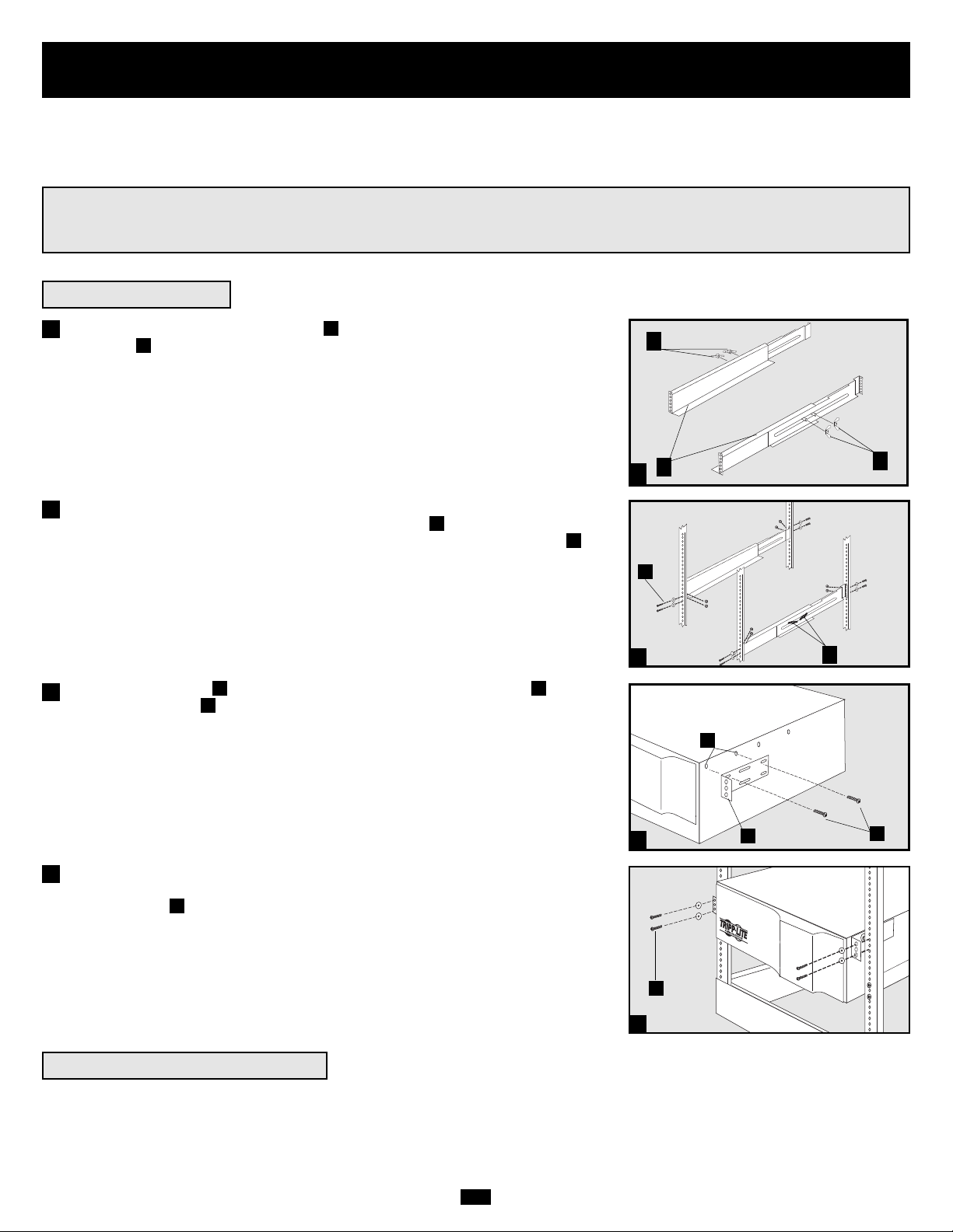
Mounting (Rack)
1
4-Post Mounting
1
2
3
A
B
C
F
E
G
4
H
Connect the two segments of each shelf using the included attached screws and
wing nuts . Leave the screws slightly loose so that the shelves can be adjusted in
the next step.
Adjust each shelf to fit your rack, then mount them in the lowest available space
of your rack with the screws, nuts and washers provided . Note that the support
ledges should face inward. Tighten the wingnuts that connect the shelf segments .
Attach mounting ears to the front mounting holes of your equipment using
the screws provided . The ears should face forward.
Using an assistant, lift your equipment and slide it onto the mounting shelves.
Attach your equipment to the rack by passing the screws, nuts and washers
(user-provided) through its mounting ears and into the rack rails.
To mount your equipment in a 2-post rack, you must purchase a Tripp Lite 2-Post
Rackmount Installation Kit (model: 2POSTRMKIT, sold separately) for each module
installed. See the Installation Kit's owner's manual for complete mounting instructions.
H
G
FE
D
C
B
A
4
Mount your equipment in either a 4-post or 2-post rack or rack enclosure.The user must determine the fitness of hardware and procedures
before mounting. If hardware and procedures are not suitable for your application, contact the manufacturer of your rack or rack enclosure.
The procedures described in this manual are for common rack and rack enclosure types and may not be appropriate for all applications.
WARNING!
All UPS System modules are extremely heavy! Use caution while lifting and mounting! User must properly
stabilize the module while lifting and mounting!
2
3
2-Post (Telecom) Mounting
B
D
Page 4
4
Mounting (Tower)
All modules can be mounted in an upright, tower position when used with optional adjustable base stands, sold separately from Tripp Lite
(model #: 2-9USTAND). When mounting modules on the adjustable base stands, make sure that the power module's control panel is towards
the top. Also, if you are installing a transformer module, place it between the power module and its battery module.
WARNING!
All UPS System modules are extremely heavy! Use caution
while lifting and mounting! User must properly
stabilize the module while lifting and mounting!
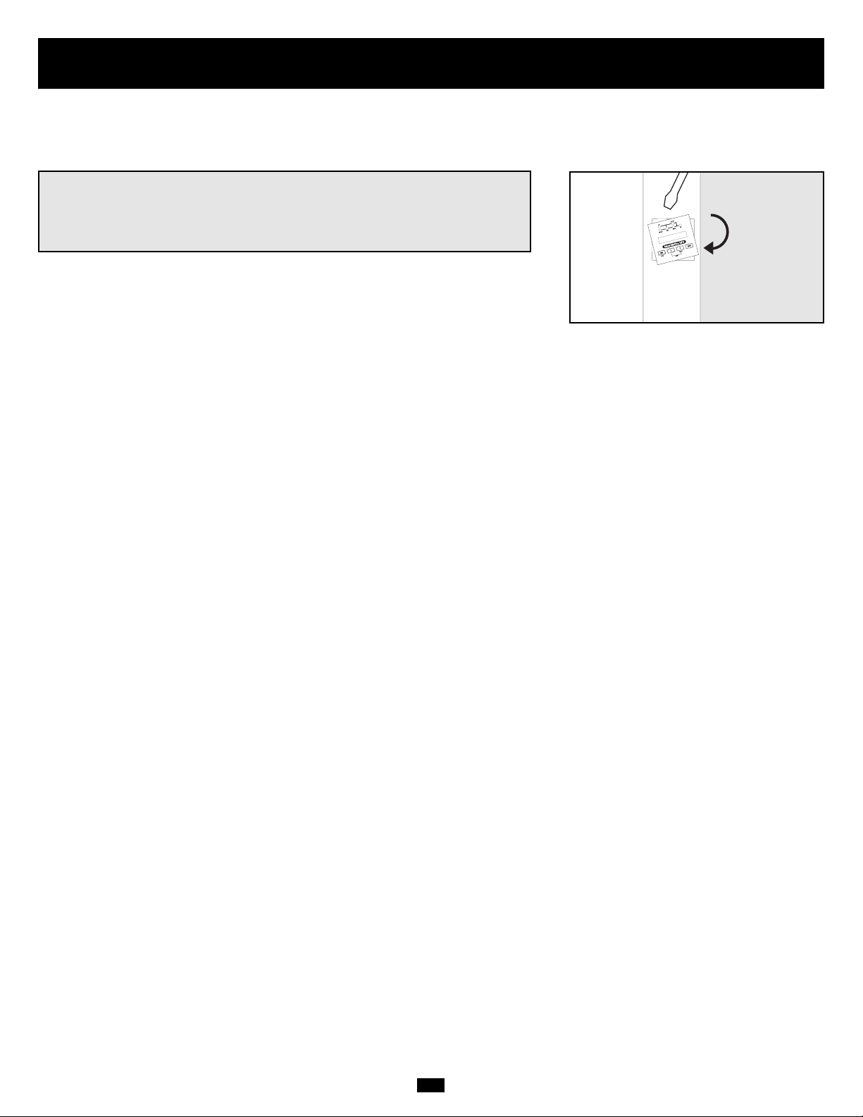
Rotate the power module’s Control Panel to view it easier while the UPS is tower
mounted. Insert a small screwdriver, or other tool, in the slots on either side of the
Control Panel. Pop the panel out; rotate it; and pop the panel back into place.
Page 5
5
Features
There are three separate UPS system modules available from Tripp Lite (a power module, a transformer module and a battery module) used
in a variety of combinations. Familiarize yourself with the location and function of the features on each module before installing and operating your UPS system. The power module is the only module which includes front panel features.
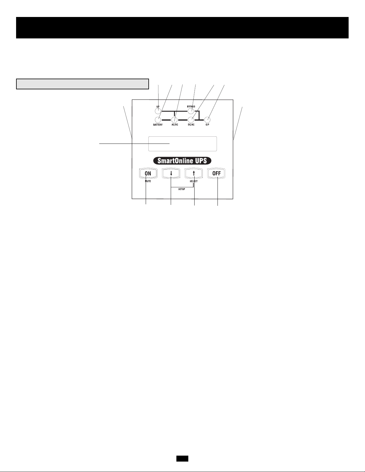
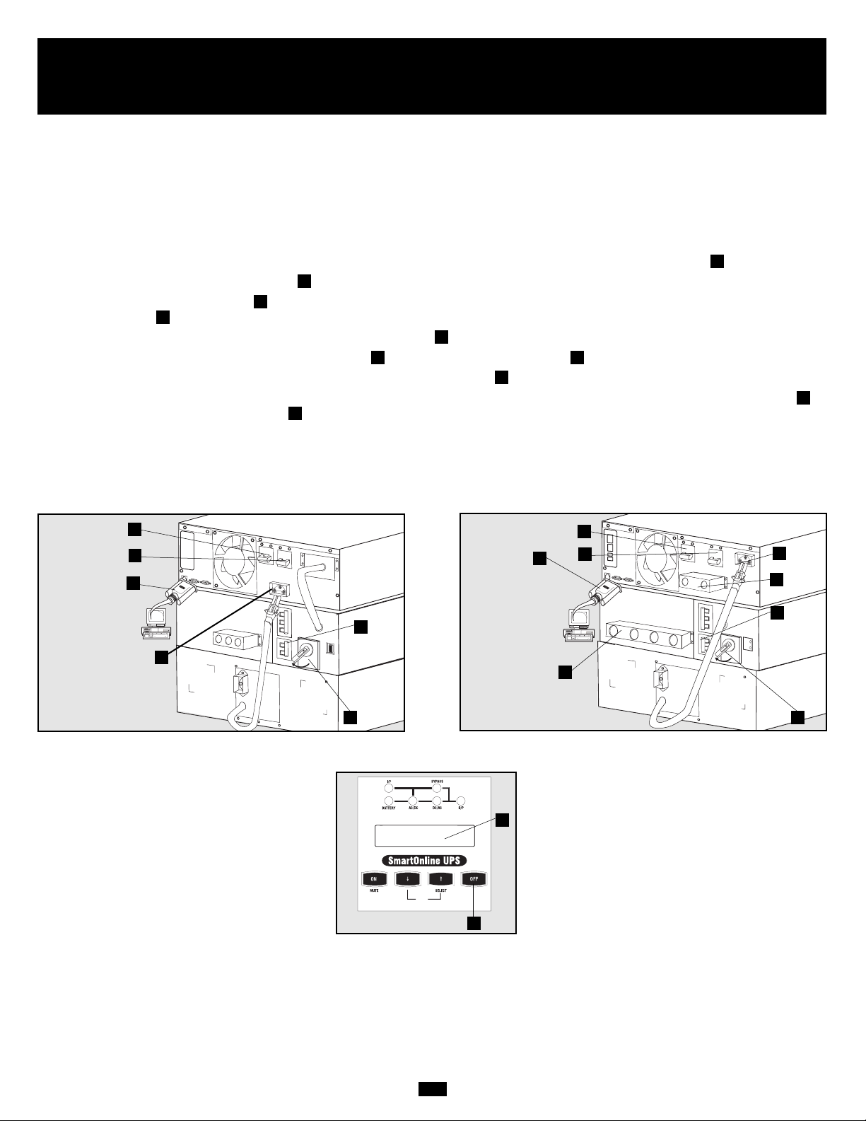
Power Module Front Panel Controls
1. LCD DISPLAY: This backlit (16 × 2 character) dot matrix display indicates a wide range of UPS operating conditions and diagnostic
data. It also displays UPS settings and options when the UPS is in setup mode.
2. ON/MUTE BUTTON: Press this button and hold it until you hear a beep to turn the UPS system’s inverter ON. If the UPS’s battery
alarm is sounding, press this button to silence it.
3. SCROLL DOWN/EXIT SETUP BUTTON: This button allows you to browse through different options and power readings on the
LCD display. Momentarily pressing it causes the LCD screen to display a different power reading (see “Operation”). Pressing it and the
SCROLL UP Button together puts the UPS in setup mode, where this button is used to scroll through setup options and to exit setup
mode.
4. SCROLL UP/SELECT BUTTON: This button allows you to browse through different options and power readings on the LCD display. Momentarily pressing it causes the LCD screen to display a different power reading (see “Operation”). Pressing it and the SCROLL
DOWN Button together puts the UPS in setup mode, where this button is used to select setup options.
5. OFF BUTTON: Press this button until you hear a beep to turn the UPS system’s inverter OFF.
6. O/P (OUTPUT) LED: This green light will illuminate to indicate your UPS is supplying AC power to connected equipment.
7. DC/AC (INVERTER) LED: This green light will illuminate to indicate the UPS’s DC/AC inverter is activated.
8. BYPASS LED: This green light will illuminate when the UPS is providing filtered mains power without engaging its converter or
inverter. If this LED is lit, connected equipment will not receive battery power in the event of a blackout.
9. AC/DC (Converter) LED: This green light will illuminate to indicate the UPS’s AC/DC converter is charging the connected battery pack(s).
10. BATTERY LED: This red light will illuminate when the UPS is discharging the battery to provide connected equipment with AC
power. An alarm will sound which can be silenced by pressing the ON/MUTE Button. This LED will remain lit after the alarm is
silenced.
11. I/P (INPUT) LED: This green light will illuminate to indicate an AC input supply is present.
12. ACCESS SLOTS: To rotate the controls, insert a flathead screwdriver into these slots and gently lever the panel out. Taking care not
to excessively twist or yank the cables connecting the controls to the rest of the UPS, turn the controls to the desired orientation and
reinsert them.
1
2 345
6879
10
11
12
12
Page 6
6
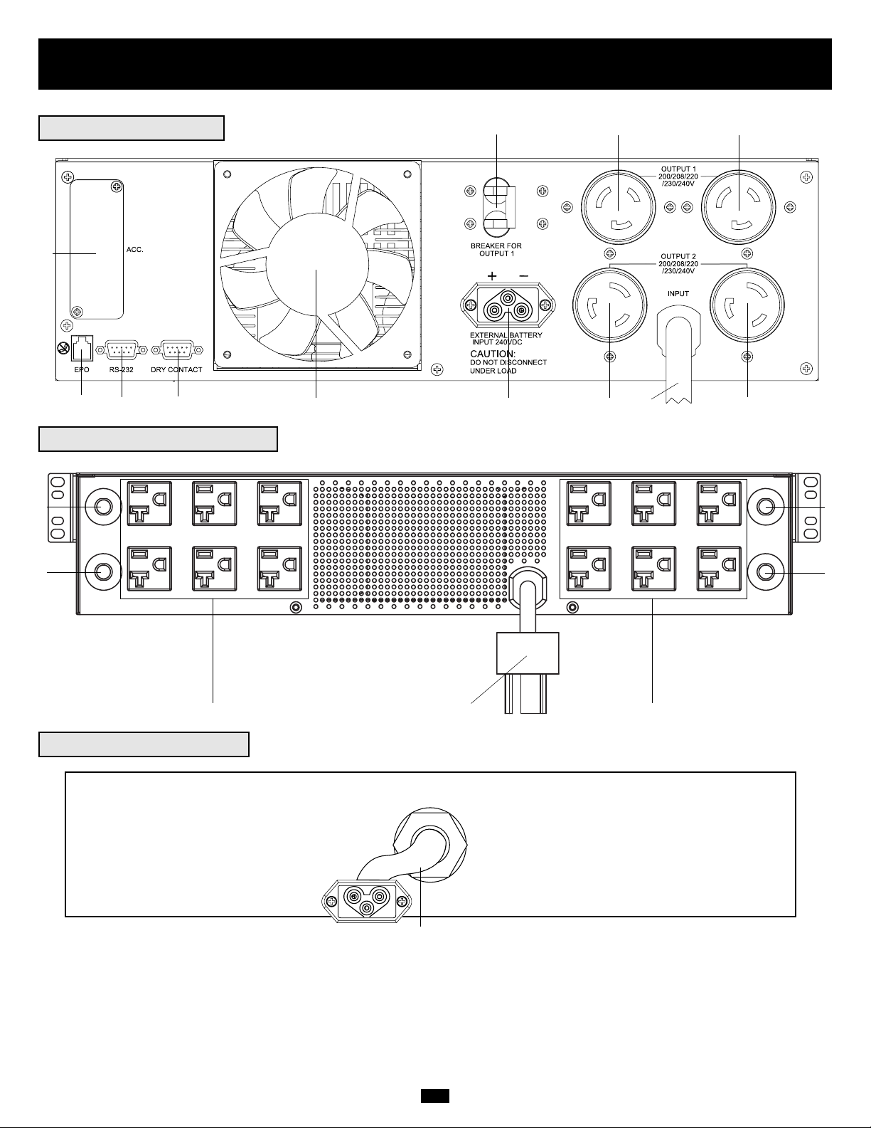
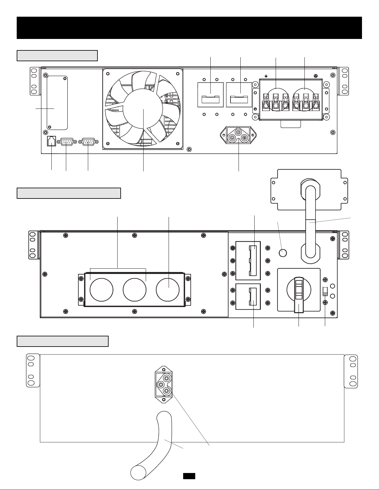
Features (Rear Panel)
see page 9 for feature descriptions
5kVA Power Module
5kVA Transformer Module
5kVA Battery Module*
* The 5kVA Power Module is shipped with a Battery Module
which is not expandable; however, the Power Module is fully
compatible with Tripp Lite Battery Modules which are
expandable (Tripp Lite model # BP240V10RT-3U, sold separately) if extended runtime is required.
11
6
7
89
10
3
12
12
13
13
14
25
25
24 26 24
25
25
28
Page 7
7
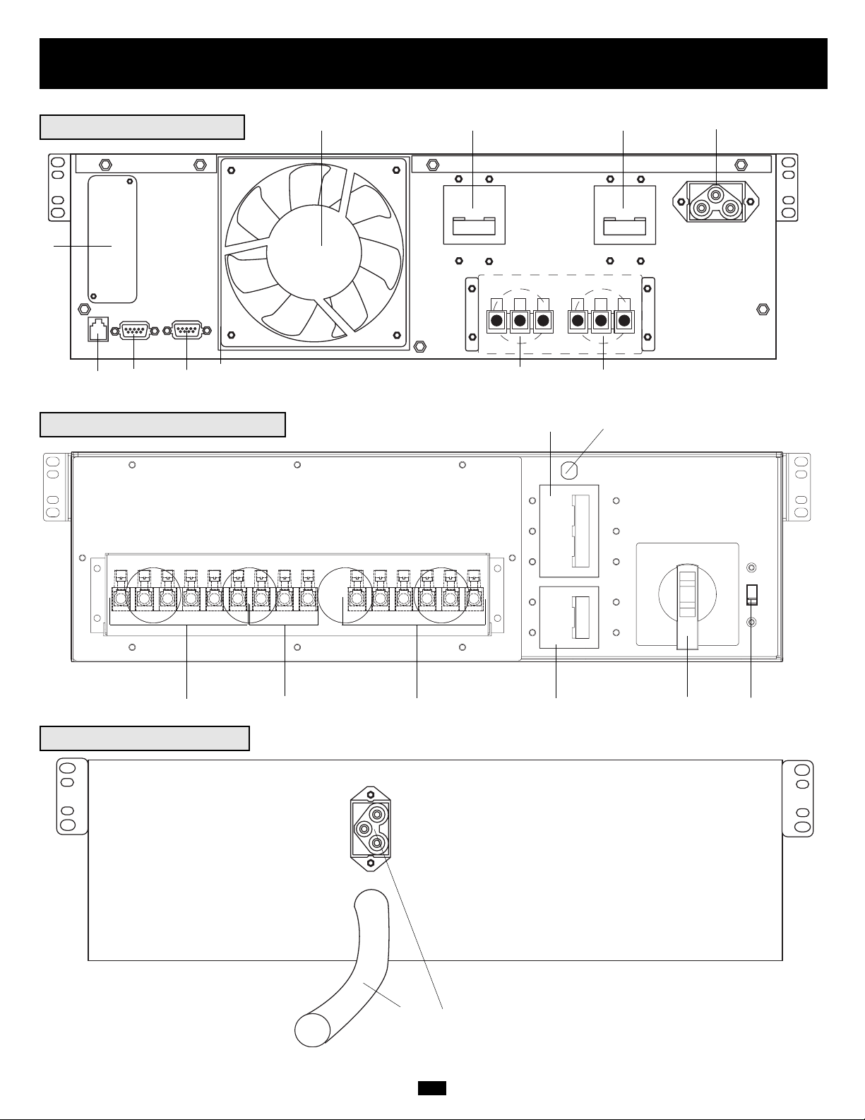
Features (Rear Panel)
see page 9 for feature descriptions
6kVA Power Module
6kVA Transformer Module
6kVA Battery Module*
54
6
7
89
10
20
20
19
16
27
28
3
1 2
15
17
22
23
* Expandable Battery Module (Tripp Lite model #
BP240V10RT-3U) shown. Depending on the model ordered,
the 6kVA Power Module may have been shipped with an
expandable Battery Module (like the one shown above) or one
which is not expandable. All 6kVA Power Modules, however,
are fully compatible with BP240V10RT-3U Battery Modules
(sold separately) if extended runtime is required.
Page 8
8
Features (Rear Panel)
see page 9 for feature descriptions
10kVA Power Module
45
6
7
8
9
10
3
10kVA Battery Module
27
28
10kVA Transformer Module
20
18
15
16
21
12
19
22 23
* Expandable Battery Module (Tripp Lite model #
BP240V10RT-3U) shown. Depending on the model ordered,
the 10kVA Power Module may have been shipped with an
expandable Battery Module (like the one shown above) or
one which is not expandable. All 10kVA Power Modules,
however, are fully compatible with BP240V10RT-3U Battery
Modules (sold separately) if extended runtime is required.
Page 9

9
Features (Rear Panel)
continued
Power Module Feature Description
1. Output Terminal Block (6kVA and 10kVA models only): Use these terminals to connect your power module to your equipment or to
the transformer module. Unscrew and remove the cover over the block for access.
2. Input Terminal Block (6kVA and 10kVA models only): Use these terminals to connect your power module to utility power or to the
transformer module. Unscrew and remove the cover over the block for access.
3. External Battery Connector: Use this to connect one or more Tripp Lite battery modules to the power module. Remove the cover for
access. The power module will not start without a connection to a charged battery module. Refer to the battery module owner’s manual
for connection instructions and safety warnings.
4. AC Input Breaker (6kVA and 10kVA models only): One double-pole circuit breaker controls input power to the power module.
5. AC Output Breaker (6kVA and 10kVA models only): One double-pole circuit breaker controls output power from the power module.
6. Exhaust Fan: This cools and ventilates the inside of the power module.
7. Accessory Slot: Remove the small cover panel to install optional accessories to remotely control and monitor your UPS system. Visit
Tripp Lite on the Web (www.tripplite.com) to learn about available SNMP, network management and connectivity products that may be
installed in this slot.
8. EPO (Emergency Power Off) Port: The power module features an EPO port that may be used to connect the power module to a contact
closure switch to enable emergency power off. See “Optional Connection” section for details.
9. RS-232 Communication Port: This female DB9 serial port may be used to connect your UPS to a workstation or server. It uses RS-232
protocol to communicate with a connected computer. It is used with Tripp Lite software and the included serial cable to monitor and
manage the UPS remotely over a network and to automatically save open files and shut down equipment during a blackout. See
“Optional Connection” for details.
10. Dry Contact Interface Port: This female DB9 port sends contact-closure signals to indicate line-fail and low-battery status. See
“Optional Connection” for details.
11. AC Output 1 Breaker (5kVA models only): One double-pole circuit breaker controls output power from the 5kVA power module's AC
receptacles labelled "Output 1."
12. AC Output 1 Receptacles (5kVA models only): Accepts direct plug-in connection of NEMA L6-20P equipment plugs.
13. AC Output 2 Receptacles (5kVA models only): Accepts direct plug-in connection of NEMA L6-30P equipment plugs. Either
receptacle also accepts direct plug-in connection of transformer connector cable (if used).
14. AC Input Cord (5kVA models only): Connects directly to wall receptacle providing 200/208/220/230 or 240V AC utility power.
Transformer Module Feature Description
15. Utility Input Terminal Block (6kVA and 10kVA models only): Use these terminals to connect your transformer module to utility
power. Unscrew and remove the cover over the block for access.
16. Equipment Output Terminal Block (6kVA and 10kVA models only): Use these terminals to connect your equipment to the transformer module. Unscrew and remove the cover over the block for access.
17. Cable for Power Module Connection (6kVA models only): Connects the transformer module to the power module’s input/output after
the power module’s terminal blocks have been removed. See “Connection” section for details.
18 Hardwire Terminal Block for Power Module Connection (10kVA models only): Use these terminals to connect the transformer mod-
ule to the power module’s input and output terminal blocks. See “Connection” section for details.
19. Overtemperature Reset Breaker (6kVA and 10kVA models only): This circuit breaker trips if the unit’s temperature climbs too high.
20. AC to UPS Breaker (6kVA and 10kVA models only): One double-pole circuit breaker controls the transformer module’s power
output to the UPS.
21. Output Breaker (6kVA and 10kVA models only): One triple-pole circuit breaker controls the transformer module’s power output to
connected equipment.
22. Manual Bypass Switch (6kVA and 10kVA models only): This red and yellow dial is used to circumvent the power module while still
supporting connected equipment when performing power module maintenance. While this switch is on BYPASS, connected equipment
will receive filtered AC mains power from the transformer module, but the equipment will not receive battery power in the event of a
blackout. See “Manual Bypass Operation” section for complete bypass procedure.
WARNING! For qualified service personnel only. Failure to follow the bypass procedure completely will not
adequately power down the UPS power module, resulting in the continued risk of death or injury from potential
contact with high voltage.
Page 10
10
Features (Rear Panel)
continued
Battery Module Feature Description
27. Input Connector (select Battery Modules only): Use this connector to daisy chain additional battery modules onto the first. Remove
the cover panel for access. Refer to the battery module owner’s manual for connection instructions and safety warnings.
28. Output Cable: Use this cable to connect the battery module to the power module or to another battery module. The power module will not start
without a connection to a charged battery module. Refer to the battery module owner’s manual for connection instructions and safety
warnings.
23. Input Voltage Select Switch (6kVA and 10kVA models only): Use this switch to set the transformer module's input voltage (either
200V AC, 208V AC or 240V AC). See “Connection” section for details.
24. AC Output Receptacles (5kVA models only): Accepts direct plug-in connection of NEMA 5-15P or NEMA 5-20P equipment plugs.
25. AC Output Breakers (5kVA models only): Push-button breakers control output power to transformer module's AC Output Receptacles
which are directly adjacent.
26. Cable for Power Module Connection (5kVA models only): Plugs directly into either of the 5kVA power module's AC Output 2
Receptacles. NOTE: this cable should only be plugged into the 5kVA power module.
Connection
• Wiring must be done by a qualified electrician.
• The UPS power module may be installed on its own or connected to an isolation transformer module. Both applications require the power module
to be connected to a battery module.
• When making wiring connections, observe the cable connection regulations appropriate to your area [e.g. National Electrical Code (NEC)
in the U.S.] at all times. Be sure to install an easily accessible disconnect switch in your installation wiring so you may cut off the UPS’s
AC input during fires and other emergencies. Ensure that cables are fitted with cable sleeves and are secured by connector clamps. Tighten
connections with a torque of not less than 24-28 inch-pounds (2.7-3.2 NM).
• Make sure that your equipment is properly grounded.
• Using cables of improper size may damage your equipment and cause fire hazards. Choose appropriate cabling and protection circuits to
make wiring connections (Ground conductors must be the same size and type as the power conductors used):
RATED INPUT CURRENT RATED OUTPUT CURRENT RATED OUTPUT CURRENT OUTPUT PROTECTION
200 - 240 (1Ø, 2-Wire + PE) 200 - 240V (1Ø, 2-Wire + PE) 120V (1Ø, 2-Wire + PE) CIRCUIT
6kVA Models 30A 8 AWG (10mm2) 30A 8 AWG (10mm2) 2 × 30A 8 AWG (10mm2) 30A
10kVA Models 50A 6 AWG (16mm2) 50A 6 AWG (16mm2) 2 × 50A 6 AWG (16mm2) 63A
Hardwiring Cautions
(6kVA & 10kVA models only)
There are three separate UPS system modules available from Tripp Lite (a power module and a battery module, which are required in all
applications, and a transformer module) used in a variety of combinations. Follow the connection procedure below which matches the combination of modules which you plan on installing.
Connecting Modules to Each Other and to Utility Power and Equipment
Page 11
11
Connection
continued
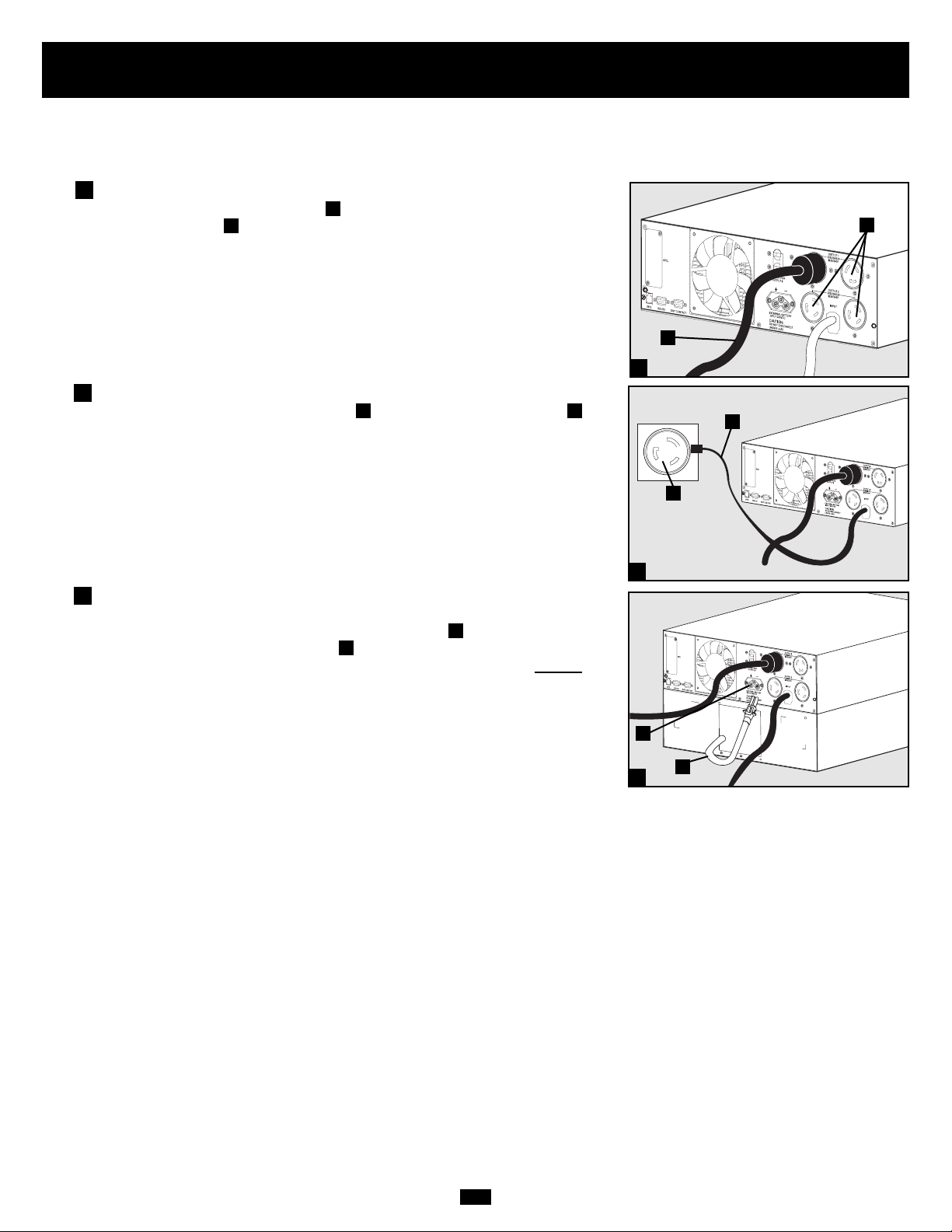
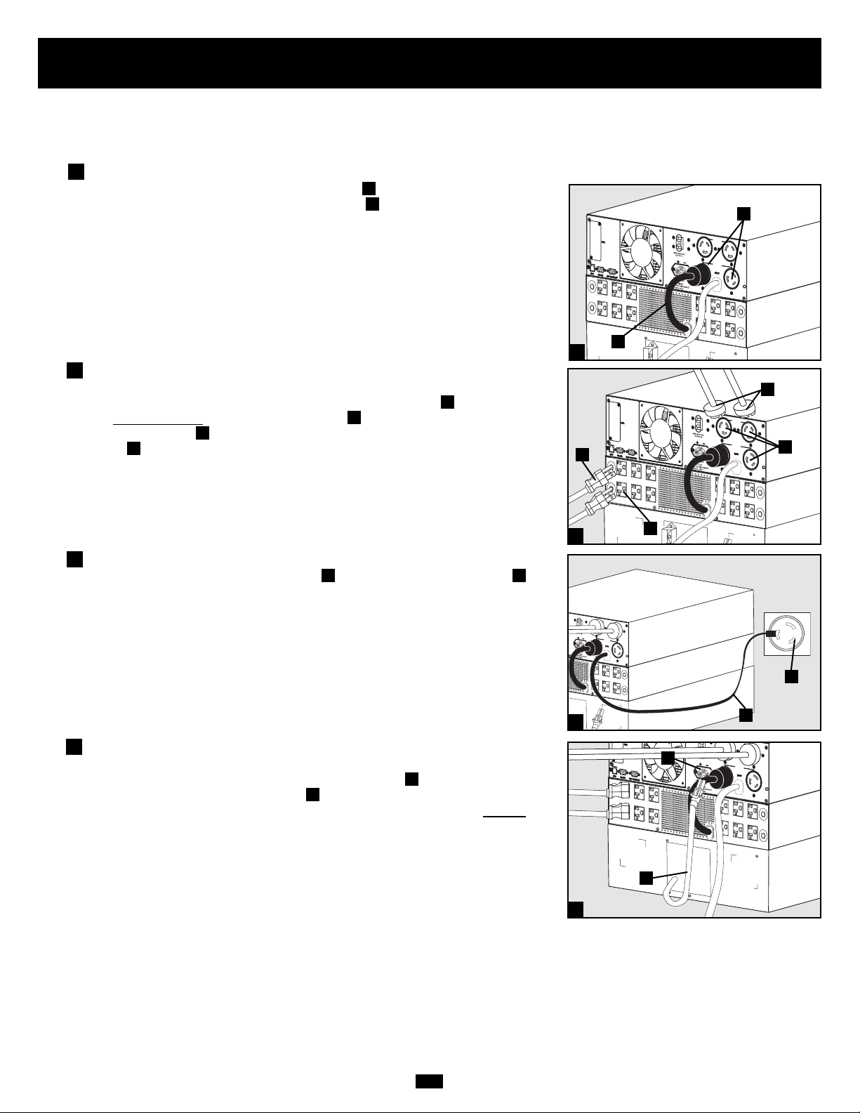
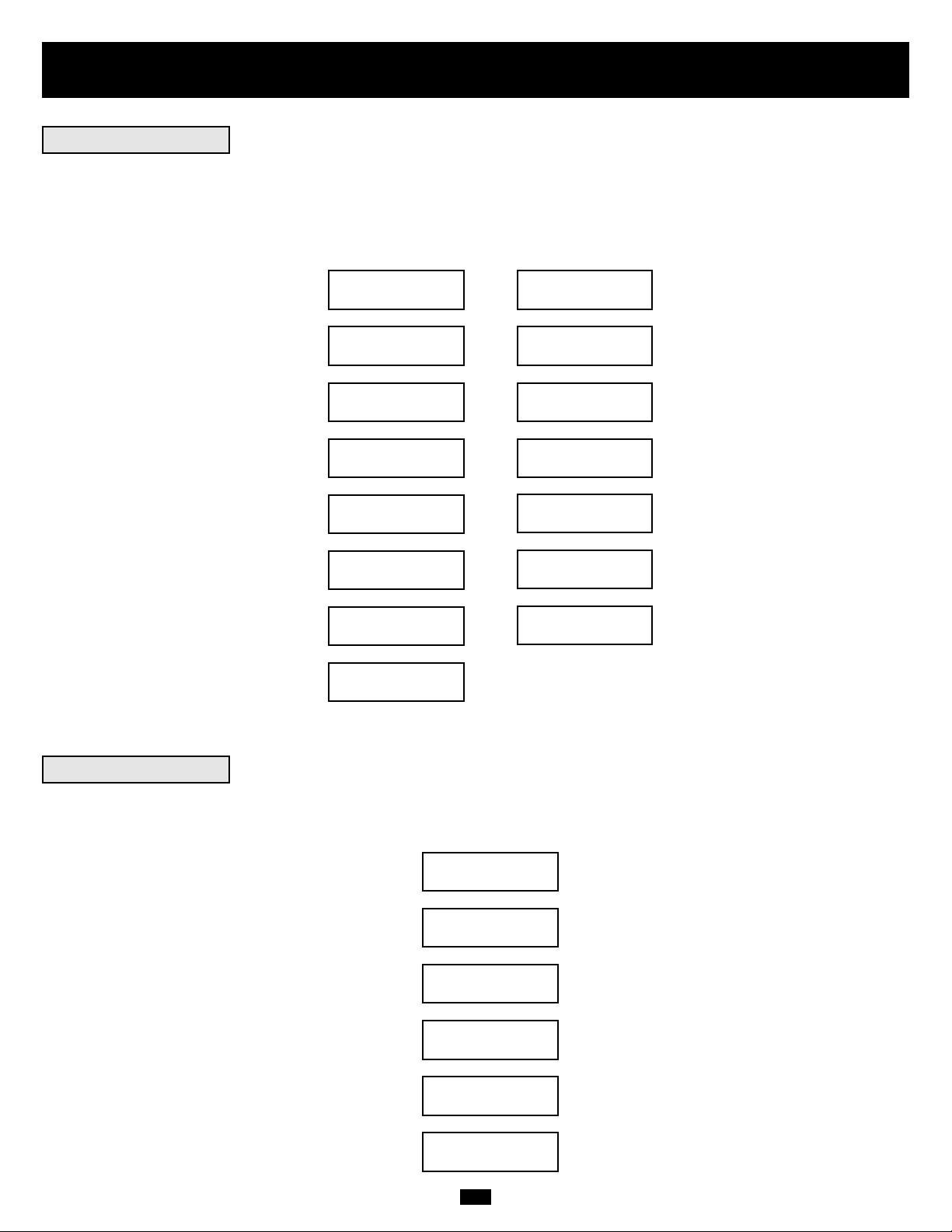
Connection Combination #1:
Power Module (5kVA) + Battery Module
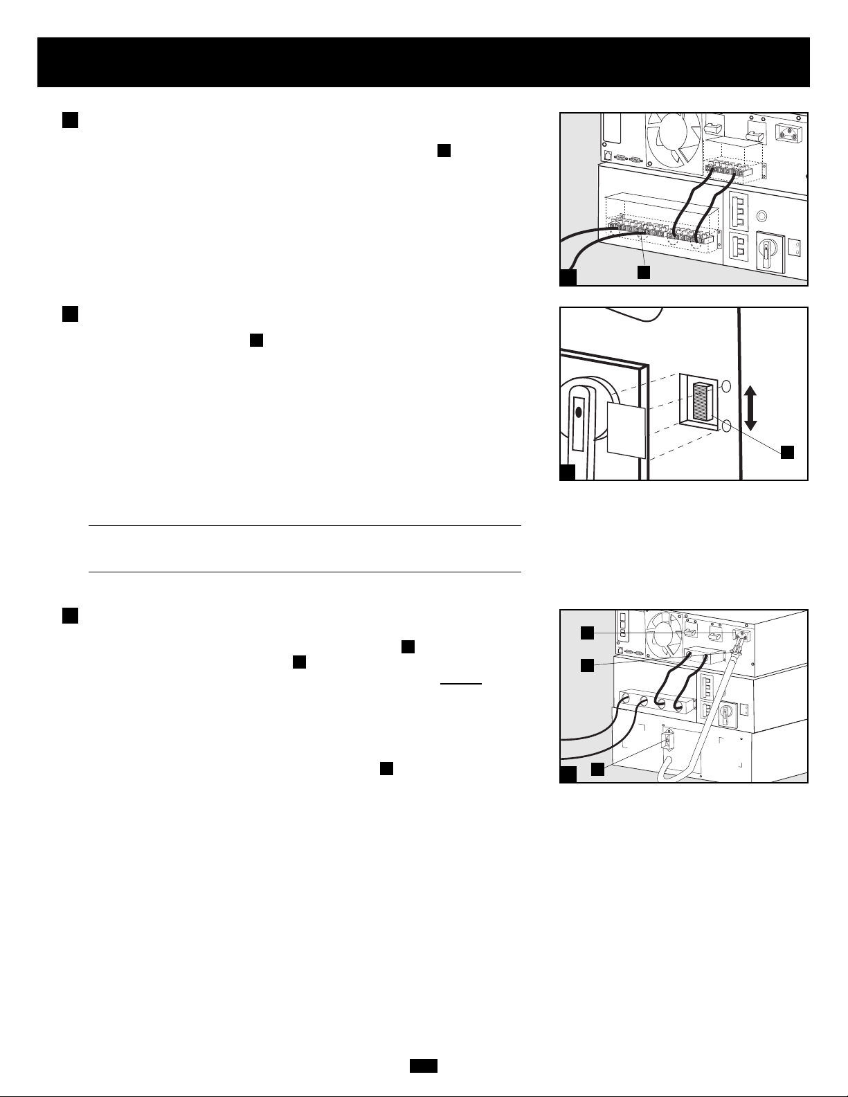
Plug your equipment into the power module.
Plug your equipment power cords directly into the power module's AC
Output Receptacles .
Plug the power module into a wall receptacle.
Plug the power module's AC input cord directly into a wall receptacle
providing 200/208/220/230 or 240V AC utility power.
Connect the battery module to the power module.
Consult the owner's manual that came with your battery module. Fully insert
the connector on the end of the battery module's cable into the connector
on the rear panel of the power module . Small sparks may occur; this is normal. NOTE: the power module does not contain internal batteries and will not
start until a battery module is connected. The battery modules are fully
charged prior to shipping. However, before expecting full backup capability
(particularly if the battery module has been stored for an extended period)
after the UPS system is connected to a utility power source, allow the battery
module to recharge for 12 hours. Once the UPS system is in use, it will charge
the batteries and maintain the charge level automatically. NOTE: The 5kVA
Power Module is shipped with a Battery Module which is not expandable;
however, the Power Module is fully compatible with Tripp Lite Battery
Modules which are expandable (Tripp Lite model # BP240V10RT-3U, sold
separately) if extended runtime is required.
F
E
DC
B
A
1
2
2
3
3
A
B
C
E
F
1
5kVA Power Module Shown
D
Page 12
12
Connection
continued
Connection Combination #2:
Power Module (5kVA) + Transformer Module (5kVA) + Battery Module
Plug the transformer module into the power module.
Plug the transformer module's connector cable directly into either of the
5kVA power module's AC Output 2 Receptacles . NOTE: this cable should
only be plugged into the 5kVA power module.
Plug your equipment into the power module and transfer module.
Plug your 200/208/220/230/240V AC equipment power cords directly into
the power module's AC Output Receptacles . Plug your 120V AC equipment power cords directly into the transformer module's AC output receptacles .
Plug the power module into a wall receptacle.
Plug the power module's AC input cord directly into a wall receptacle
providing 200/208/220/230 or 240V AC utility power.
Connect the battery module to the power module.
Consult the owner's manual that came with your battery module. Fully insert
the connector on the end of the battery module's cable into the connector
on the rear panel of the power module . Small sparks may occur; this is normal. NOTE: the power module does not contain internal batteries and will not
start until a battery module is connected. The battery modules are fully
charged prior to shipping. However, before expecting full backup capability
(particularly if the battery module has been stored for an extended period)
after the UPS system is connected to a utility power source, allow the battery
module to recharge for 12 hours. Once the UPS system is in use, it will charge
the batteries and maintain the charge level automatically. NOTE: The 5kVA
Power Module is shipped with a Battery Module which is not expandable;
however, the Power Module is fully compatible with Tripp Lite Battery
Modules which are expandable (Tripp Lite model # BP240V10RT-3U, sold
separately) if extended runtime is required.
J
I
HG
F
E
D
C
B
A
1
2
2
3
3
A
B
E
H
G
1
5kVA Power Module Shown
4
4
F
D
C
I
J
Page 13
13
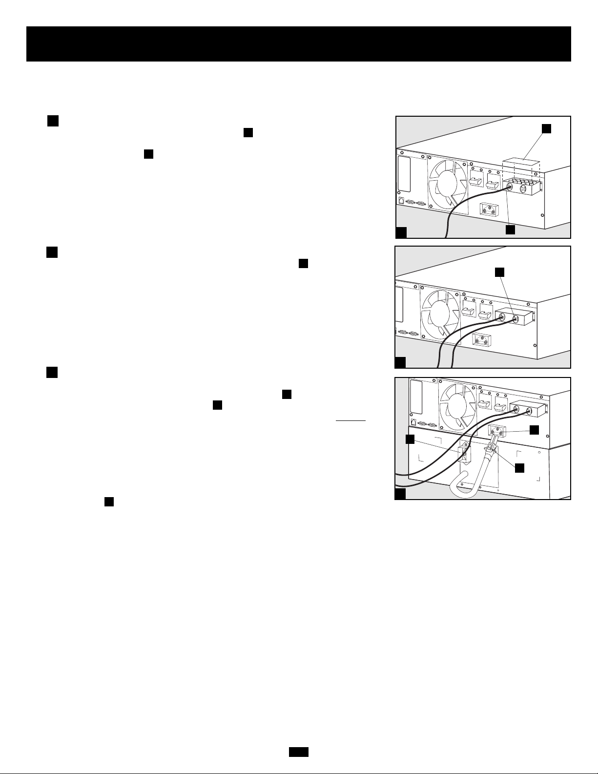
Connection Combination #3:
Power Module (either 6kVA or 10kVA) + Battery Module(s)
Hardwire the power module to your equipment.
Using a screwdriver, remove the top of the box covering the power module’s
input and output terminals. Pass a user-supplied cable through the terminal
box’s left knockout and connect it to the power module’s output terminals.
Connect the other end of the cable to your equipment.
Hardwire the power module to a utility power source.
Pass a user-supplied cable through the box’s right knockout and connect it
to the power module’s input terminals. Replace the top of the terminal box.
Connect the other end of the cable to a utility power source.
Connect the battery module to the power module.
Consult the owner’s manual that came with your battery module. Fully insert
the connector on the end of the battery module’s cable into the connector
on the rear panel of the power module . Small sparks may occur; this is normal. NOTE: the power module does not contain internal batteries and will not
start until a battery module is connected. The battery modules are fully charged
prior to shipping. However, before expecting full backup capability (particularly
if the battery module has been stored for an extended period) after the UPS system
is connected to a utility power source, allow the battery module to recharge for
12 hours. Once the UPS system is in use, it will charge the batteries and maintain
the charge level automatically. If needed, connect additional battery modules
in a daisy-chain with each module’s cable inserted into the previous module’s
connector .
F
E
D
C
B
A
1
2
2
3
3
A
B
C
D
E
F
1
6kVA Power Module Shown
Connection
continued
Page 14
14
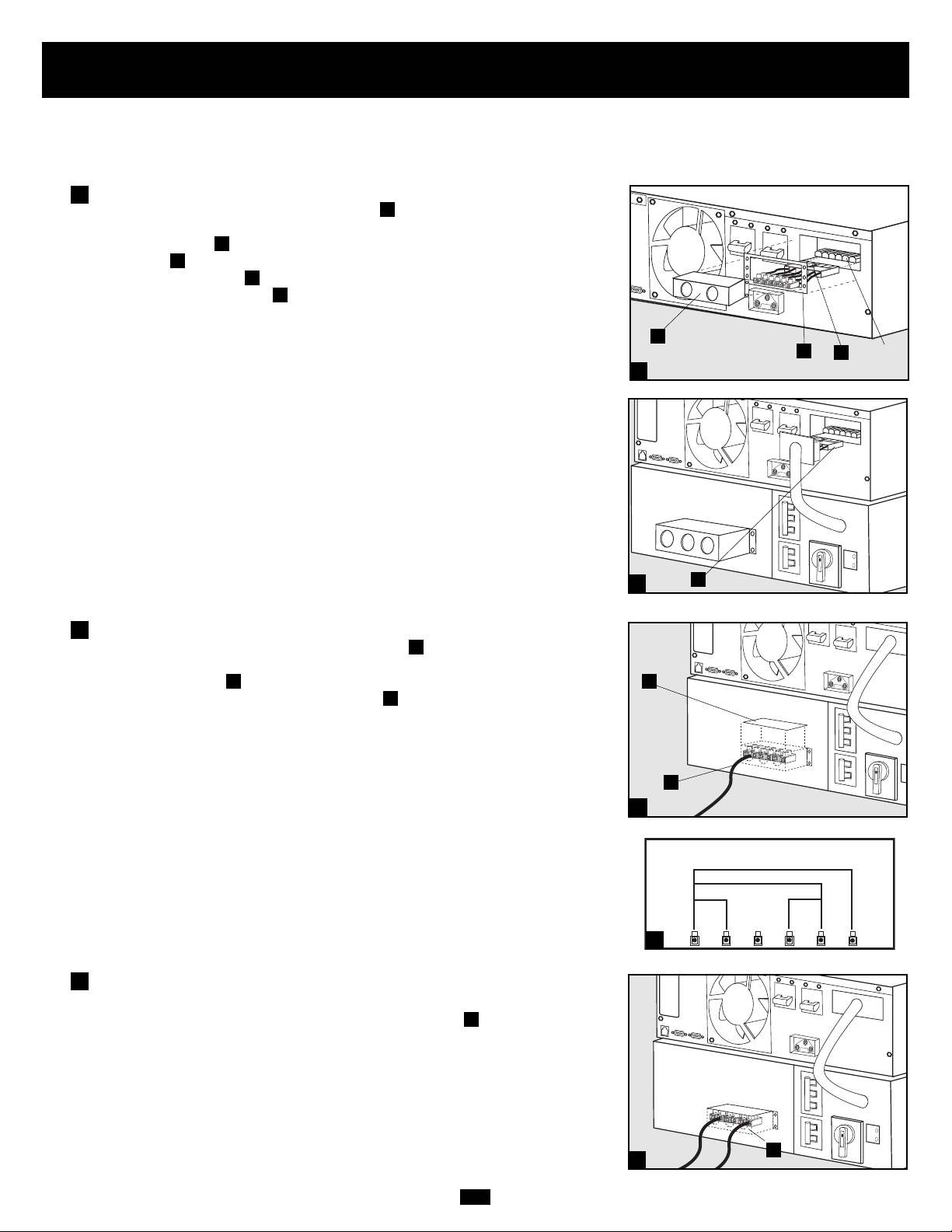
Connection Combination #4:
Power Module (6kVA) + Transformer Module (6kVA) + Battery Module(s)
Connect the power module to the transformer module.
Using a screwdriver, remove the entire box covering the power module’s
input and output terminals. Remove the screws on either side of the terminals.
Grip the terminals and slide them out until you can view the cable connector
release tab . Press the tab down and pull on the cables to release them from
the internal connector . Remove the terminals. Insert the connector cable
from the transformer module into the internal connectors in the power module’s
terminal box until the release tab clicks in place. Replace the screws around
the plate. Although they are not needed, retain the power module’s terminals
and terminal box cover in case you plan to operate the power module without
the transformer module at a future date.
Hardwire the transformer module to your equipment.
Using a screwdriver, remove the top of the box covering the transformer
module’s input and output terminals. Pass a user-supplied cable through the
box’s left knockout and connect it to the transformer module’s output terminals. See the AC Output Voltage Diagram to determine which terminal
connections will provide voltage appropriate to your application. Connect the
other end of the cable to your equipment.
Hardwire the transformer module to a utility
power source.
Pass a user-supplied cable through the box’s right knockout and connect it to
the transformer module’s input terminals. Replace the top of the box covering
the transformer module’s terminals. Connect the other end of the cable to a utility
power source.
I
H
G
F
E
D
C
B
A
1
1
3
Connection
continued
2
2
3
1
A
B
C
E
G
I
F
Connection Combination #4 continued on next page
H
N
O
R
M
AC OUTPUT VOLTAGE DIAGRAM
208
V
240
120
V
V
120
V
G
A
L
BY
PAS
S
N
O
R
M
A
L
BY
PAS
S
N
O
R
M
A
L
BY
PAS
S
Page 15
15
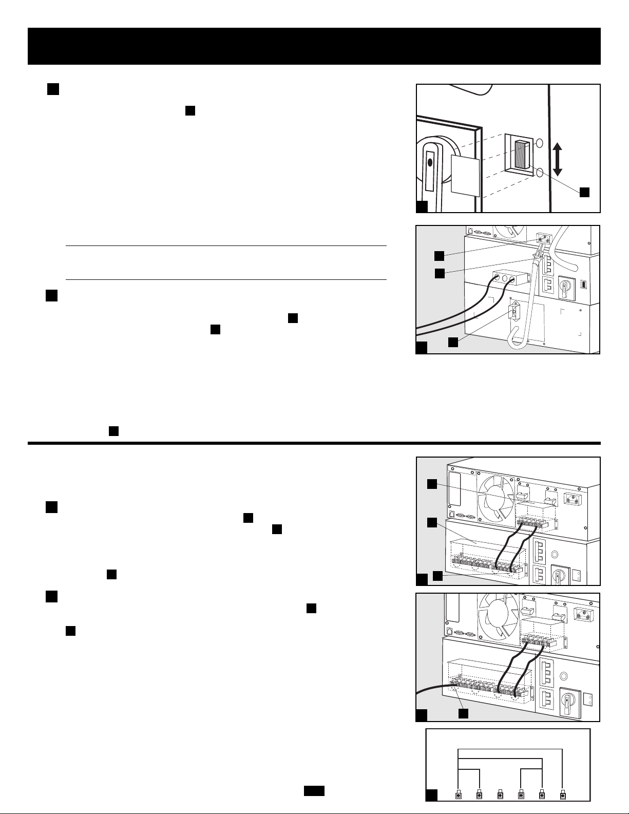
Select the transformer module’s input voltage.
Using a screwdriver, remove the panel covering the transformer module’s
Input Voltage Select Switch . Set the switch to match your facility’s input
voltage. Then, use the power module’s front panel switches to configure input
voltage on the LCD Display (see “Configure your UPS’s input and output” in
the “Power ON/OFF” section on page 14).
IMPORTANT NOTE: if your facility’s input voltage is 200VAC, set the transformer module’s switch to 240VAC, but configure the power module to 200V
AC. If your facility’s input voltage is either 208V AC or 240V AC, the transformer module and power module settings must match. The factory default
settings for both modules is 208V. See chart below.
Transformer Module Power Module
Your Facility's Input Voltage Setting Input Voltage Setting
Input Voltage (Rear Panel Switch) (Front Panel Switches/LCD Display)
240V AC 240V AC 240V AC
208V AC 208V AC 208V AC
200V AC 240V AC 200V AC
Connect the battery module to the power module.
Consult the owner’s manual that came with your battery module. Fully insert
the connector on the end of the battery module’s cable into the connector on
the rear panel of the power module . Small sparks may occur; this is normal.
NOTE: the power module does not contain internal batteries and will not start
until a battery module is connected. The battery modules are fully charged prior
to shipping. However, before expecting full backup capability (particularly if
the battery module has been stored for an extended period) after the UPS system
is connected to a utility power source, allow the battery module to recharge for
12 hours. Once the UPS system is in use, it will charge the batteries and maintain
the charge level automatically. If needed, connect additional battery modules in
a daisy-chain with each module’s cable inserted into the previous module’s
connector .
Connection Combination #5: Power Module (10kVA)
+ Transformer Module (10kVA) + Battery Module(s)
Hardwire the power module to the transformer module.
Using a screwdriver, remove the top of the box covering the power module’s input
and output terminals. Remove the top of the box covering the transformer
module’s terminals. With supplied cable, connect the power module’s input and
output terminals to the corresponding terminals on the transformer module’s
“Hardwire Terminal Block for Power Module Connection” in the box’s right
knockout .
Hardwire the transformer module to your equipment.
Pass a user-supplied cable through the box’s left knockout and connect it to
the transformer module’s output terminals. See the AC Output Voltage Diagram
to determine which terminal connections will provide voltage appropriate to
your application. Connect the other end of the cable to your equipment.
E
D
C
B
A
M
L
K
J
Connection
continued
4
5
5
1
1
2
2
4
J
M
L
A
B
C
D
K
Connection Combination #5 continued on next page
E
NORMAL
PAS S
BY
240V AC
208V AC
N
O
R
M
A
L
BY
PAS
S
AC OUTPUT VOLTAGE DIAGRAM
208
V
240
120
V
V
120
V
G
NORMAL
BY
PAS
S
N
O
R
M
A
L
BY
PASS
Page 16
16
Connection
continued
Hardwire the transformer module to a utility
power source.
Pass a user-supplied cable through the box’s middle knockout and connect
it to the transformer module’s input terminals. Connect the other end of the
cable to a utility power source. Replace the top of the boxes covering the power
module’s and transformer module’s terminals.
Select the transformer module’s input voltage.
Using a screwdriver, remove the panel covering the transformer module’s
Input Voltage Select Switch . Set the switch to match your facility’s input
voltage. Then, use the power module’s front panel switches to configure input
voltage on the LCD Display (see “Configure your UPS's input and output” in
the “Power ON/OFF” section).
IMPORTANT NOTE: if your facility's input voltage is 200V AC, set the transformer module’s switch to 240VAC, but configure the power module to 200V
AC. If your facility’s input voltage is either 208V AC or 240V AC, the transformer module and power module settings must match. The factory default
settings for both modules is 208V. See chart below.
Transformer Module Power Module
Your Facility’s Input Voltage Setting Input Voltage Setting
Input Voltage (Rear Panel Switch) (Front Panel Switches/LCD Display)
240V AC 240V AC 240V AC
208V AC 208V AC 208V AC
200V AC 240V AC 200V AC
Connect the battery module to the power module.
Consult the owner’s manual that came with your battery module. Fully insert
the connector on the end of the battery module’s cable into the connector
on the rear panel of the power module . Small sparks may occur; this is normal.
NOTE: the power module does not contain internal batteries and will not supply
power to connected equipment until a battery module is connected. The battery
modules are fully charged prior to shipping. However, if the battery module
has been stored for an extended period, after the UPS system is connected to a
utility power source, allow the battery module to recharge for 12 hours. If
needed, connect additional battery modules in a daisy-chain with each module’s
cable inserted into the previous module’s connector .
J
I
H
G
F
3
3
4
5
5
F
4
G
H
I
J
N
O
R
M
A
L
BY
PAS
S
PAS S
240V AC
BY
208V AC
NORMAL
N
O
R
M
A
L
BY
PAS
S
Page 17
17
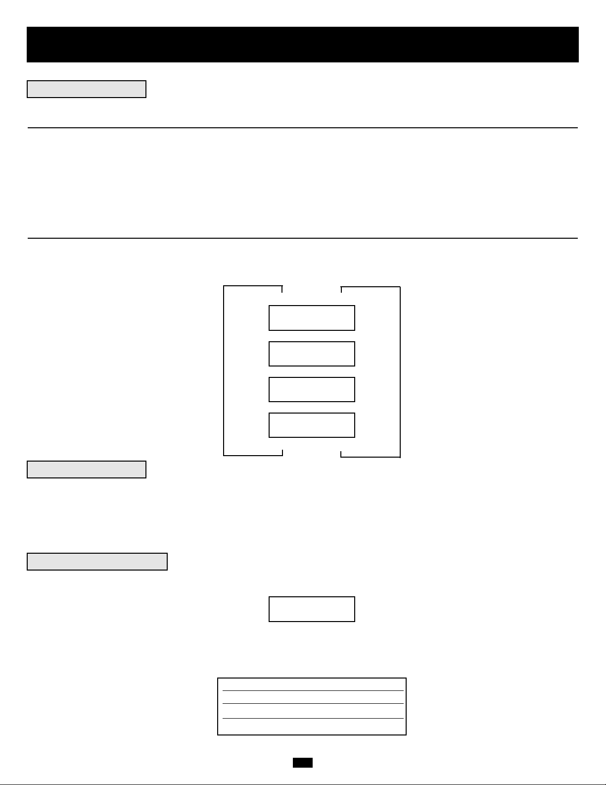
The following connections are optional. Your UPS system will function properly without
these connections.
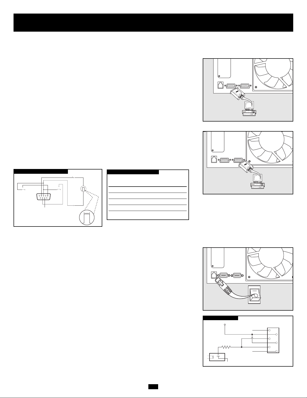
RS-232 Serial Communication Connection
Use the included cable to connect the power module’s “RS-232” port to the communication
port on your computer. This will allow full network monitoring and control of your
UPS system. Install on your computer the Tripp Lite PowerAlert Software appropriate
to your computer’s operating system.
Contact-Closure Communication Connection
Use a user-supplied contact-closure DB9 cable to connect the power module’s “DryContact” port to the communication port on your computer or other equipment. This
will allow basic contact-closure signals to be sent to and from the UPS. Refer to the
following diagram and table to determine the signals carried by this port. Install on your
computer the Tripp Lite PowerAlert Software appropriate to your computer’s operating system.
EPO Port Connection
This optional feature is only for those applications which require connection to a facility’s
Emergency Power Off (EPO) circuit. When the power module is connected to this circuit,
it enables emergency shutdown of the output. Using the included cable, connect the
power module’s EPO port to a user-supplied remote switch. The pin assignments for the
EPO port are shown in the following diagram. Note: if there is a short between pins 2
and 3, 2 and 5, 4 and 5, or 3 and 4, the UPS system will power off.
Optional Connection
DRY CONTACT INTERFACE DIAGRAM
UPS Operating Pin 8,3 Pin 1,3 Pin 6,3
Mode
Normal OPEN OPEN *
Back Up CLOSE * *
Low Battery CLOSE CLOSE *
Fault * * CLOSE
* Inactive: may be in either state
DRY CONTACT INTERFACE TABLE
EPO PIN ASSIGNMENT
LOW BATTERY
NO
COM NC
MAXIMUM CAPACITY OF DRY CONTACT: AC250V/3A • DC30V/3A
54321
9
8
7
SIGNAL FROM COMPUTER
6
BACK-UP
NO
COM NC
lm in. > 3.3 mA
REMOTE SHUTDOWN SIGNAL
FROM EXTERNAL
>2 sec
12 V
0
12V
1
X
2
3
1K
4
5
6
X
Page 18
18
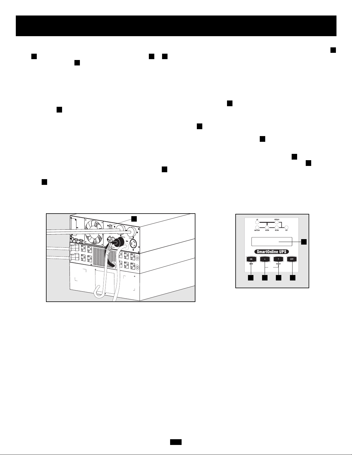
1. Configure your UPS’s input and output: Put your UPS power module into setup mode by holding down both of its scroll buttons (
and ) at once. Scroll through the setup options (using or ) and select the appropriate setting for each of the following options using
the “SELECT” button .
• Input & Output Voltage: Select 200, 208 or 240 VAC.
• Output Frequency: Your UPS will autoselect 50 or 60 Hz to match the input.
• Economy Mode: Your UPS can provide on-line operation with zero transfer time. It can also operate in a more energy-efficient
line-interactive mode. Select Economy On to put the UPS in line-interactive mode. Select Economy Off to put the UPS in on-line mode.
• After you have set these options, “exit” the setup mode with the scroll button , then exit bypass mode by holding the ON
button down until you hear a beep.
2. Turn input to the UPS ON: Press and hold the power module's ON button until you hear a beep to start your UPS in ON BATTERY
mode. Note that some electronic equipment may draw more amps during startup; when starting from battery, consider reducing the initial load on the UPS. Your UPS will perform a brief self-test and show the results on the LCD Display . See "Startup Self-Test" in the
"Operation" section for the display sequence.
3. To turn the UPS power module and transformer module (if used) OFF: Press the power module's OFF button until you hear a
beep. Your load will still be energized. The inverter is now off, but your UPS is not fully deactivated. The LCD Display will show
BYPASS MODE. Turn the power module's Output Breaker OFF. Unplug the power module's AC input cord from the wall outlet. If
a transformer module is used, unplug its connector cable from the power module. Your load will no longer be energized, and the LCD
Display will be dark.
D
E
D
F
D
C
C
A
B
BAB
A
Power ON/OFF (5kVA models only)
5kVA Models
5kVA Models
(Front Panel)
D
C
A
B F
E
Page 19
19
1. Configure your UPS’s input and output: Put your UPS power module into setup mode by holding down both of its scroll buttons (
and ) at once. Scroll through the setup options (using or ) and select the appropriate setting for each of the following options using
the “SELECT” button .
• Input & Output Voltage: Select 200, 208 or 240 VAC.
• Output Frequency: Your UPS will autoselect 50 or 60 Hz to match the input.
• Economy Mode: Your UPS can provide on-line operation with zero transfer time. It can also operate in a more energy-efficient
line-interactive mode. Select Economy On to put the UPS in line-interactive mode. Select Economy Off to put the UPS in on-line mode.
• After you have set these options, “exit” the setup mode with the scroll button , then exit bypass mode by holding the ON
button down until you hear a beep.
2. Turn input to the UPS ON: If the UPS power module is connected to a transformer module, turn the tranformer module’s AC-to-UPS
and Output Circuit Breakers on. Turn the UPS power module’s Input Circuit Breaker on. Press the UPS power module’s ON button
until you hear a beep to begin inverter operation. If your AC input is not providing power normally, you may “cold start” your UPS
from battery. (Your battery must be at least partially charged for this operation to succeed.) Press and hold the ON button until you
hear a beep to start your UPS in ON BATTERY mode. Note that some electronic equipment may draw more amps during startup; when
starting from battery, consider reducing the initial load on the UPS. Your UPS will perform a brief self-test and show the results on the
LCD Display . See “Startup Self-Test” in the “Operation” section for the display sequence.
3. Turn UPS output ON: Turn the UPS power module’s Output Circuit Breaker ON. If the UPS is connected to a transformer module, turn
the transformer module’s Manual Bypass Switch from BYPASS to NORMAL and its Output Circuit Breaker ON. Your UPS will now
provide power to connected equipment.
4. To turn the UPS power module and transformer module OFF: Press the UPS power module’s OFF button until you hear a beep.
Your load will still be energized. The inverter is now off, but your UPS is not fully deactivated. The LCD Display will show BYPASS
MODE. Turn the UPS power module’s Input and Output Circuit Breakers ( and ) OFF. If the UPS is connected to a transformer module,
turn the transformer module’s power AC-to-UPS and Output Circuit Breakers OFF. Your load will no longer be energized, and the
LCD Display will be dark.
F
D
GE
F
I
H
G
F
C
C
ED
C
A
B
BAB
A
Power ON/OFF (6kVA and 10kVA models only)
6kVA Models
10kVA Models
D
E
G
H
E
G
H
6kVA & 10kVA Models
(Front Panel)
D
F
C
A
B I
NORMAL
BY
PAS
S
N
O
R
M
A
L
B
Y
P
A
S
S
Page 20
20
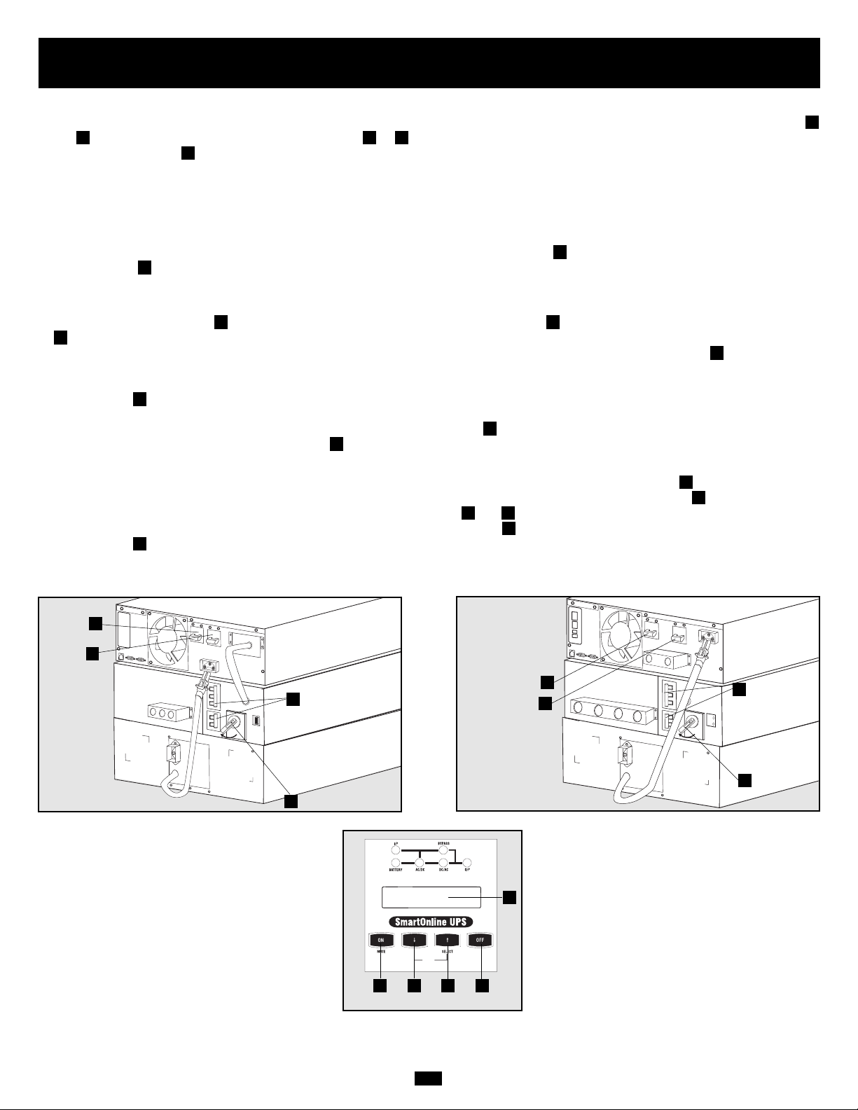
Manual Bypass Operation (6kVA and 10kVA models
only)
(for power module maintenance or replacement)
The following procedure only applies to UPS system configurations that include a 6kVA or 10kVA transformer module. The procedure
details how to service or replace the power module while supplying equipment connected to the transformer module with utility power.
NOTE: since the power module and battery module will be disconnected during the procedure, they will be unable to supply battery backup
support to equipment connected to the transformer module in the event of a blackout.
WARNING! For qualified service personnel only. Failure to follow this procedure completely will not adequately power down the
UPS power module, resulting in the continued risk of death or injury from potential contact with high voltage.
1. Disable PowerAlert Software and disconnect communication cable from the power module’s communication ports .
2. Turn transformer module’s Bypass Switch to “BYPASS”.
3. Press power module’s OFF Button , if power module is powered, until a beep is heard and a “BYPASS MODE” message is displayed
in the LCD panel .
4. Turn off the transformer module's double-pole AC to UPS breaker .
5. Turn off the power module’s double-pole input breaker and double-pole output breaker .
6. Disconnect battery module cable from the power module’s battery connector .
7. FOR 10kVA POWER MODULES ONLY: Use a voltage meter to check the cable connecting the power module’s terminal blocks to
the transformer module’s terminal blocks to ensure the power module is no longer powered. Once it is no longer powered, remove the
cabling.
The power module is now safely powered down and maintenance/replacement can be performed.
J
I
H
GF
E
D
C
B
A
6kVA Models (Rear Panel)
10kVA Models (Rear Panel)
A
B
F
G
A
B
F
G
I
E
D
C
6kVA & 10kVA Models
(Front Panel)
H
E
H
J
N
O
R
M
A
L
BY
PAS
S
N
O
R
M
A
L
B
Y
P
A
S
S
Page 21
21
DIAGNOSTIC MODE
AC/DC OK
DIAGNOSTIC MODE
TESTING INVERTER
ON BATTERY MODE
LOAD = XXX% X.XXKW
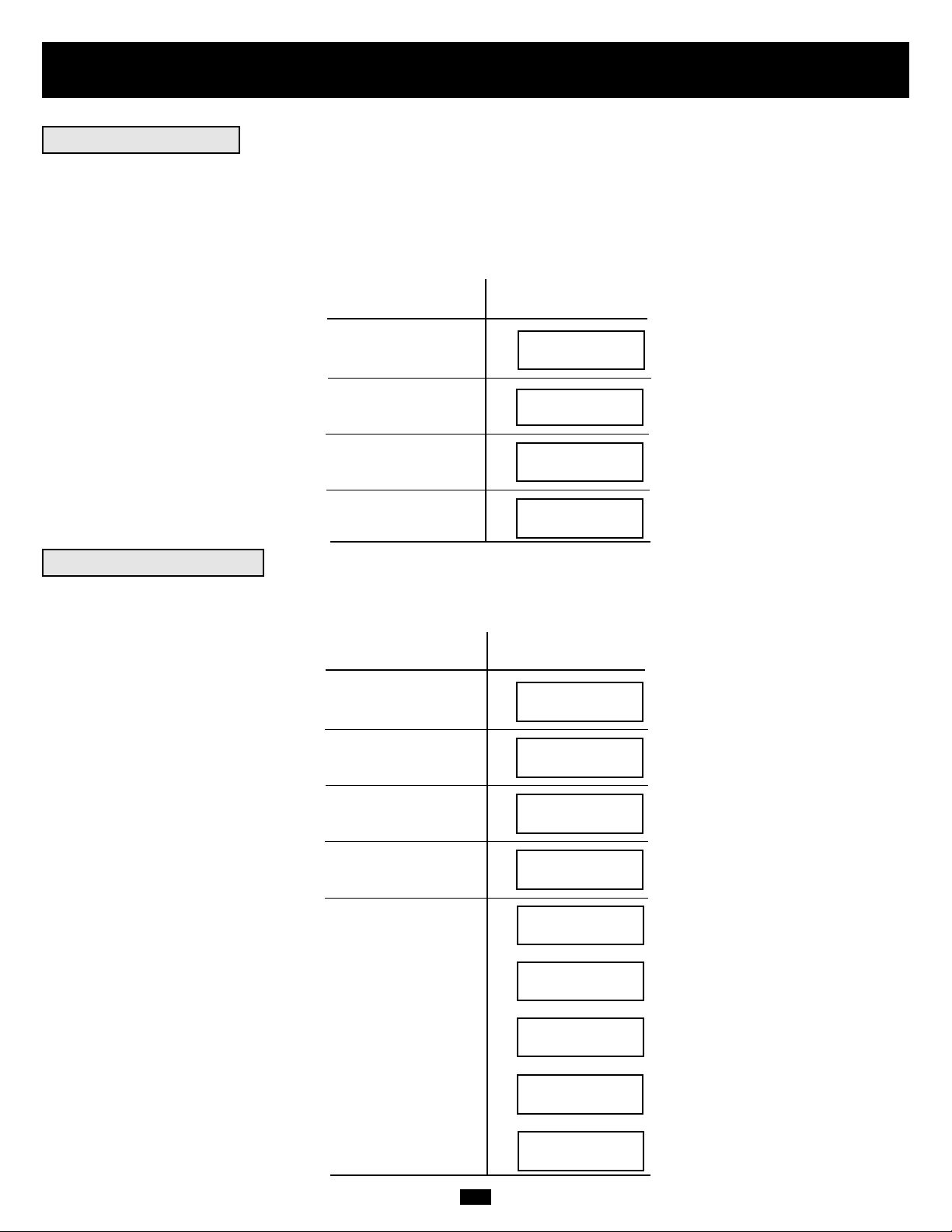
Operation
When you turn the UPS ON, it will enter Diagnostic Mode and perform a brief self-test lasting about 15 seconds. The results of the self-test
are shown on the LCD screen in the sequence below.
DIAGNOSTIC MODE
FREQ OUT = XXHz
DIAGNOSTIC MODE
INPUT AC OK
DIAGNOSTIC MODE
INPUT AC OK
DIAGNOSTIC MODE
BATTERY OK
DIAGNOSTIC MODE
CHARGER OK
DIAGNOSTIC MODE
AC/DC OK
DIAGNOSTIC MODE
TESTING INVERTER
ONLINE MODE
LOAD = XXX% X.XXKW
DIAGNOSTIC MODE
FREQ OUT = XXHz
DIAGNOSTIC MODE
INPUT AC BAD
DIAGNOSTIC MODE
INPUT AC BAD
DIAGNOSTIC MODE
BATTERY OK
M
M
M
M
M
M
M
M
M
M
M
M
M
STARTED WITH
AC INPUT
COLD
START*
*Note: If the UPS is cold started, its BATTERY LED will be lit.
If a problem is detected during the self-test, the LCD will display a error message. If your UPS displays any of the following messages in
its LCD, call Tripp Lite Technical Support at (773) 869-1234 for service.
BAD BATTERY!
CALL FOR SERVICE
CHARGER FAILURE!
CALL FOR SERVICE
AC/DC FAILURE!
CALL FOR SERVICE
INVERTER FAILURE!
CALL FOR SERVICE
OUTPUT FAILURE!
CALL FOR SERVICE
FAN FAILURE!
CALL FOR SERVICE
Startup Self-Test
Failed Self-Test
Page 22
22
Operation
continued
During normal operation, the first line of your LCD Display shows which operating mode your UPS is in: Online, Economy, On Battery,
or Bypass.
Online mode: The UPS provides AC power while utility power is available and switches to On Battery mode instantly (zero transfer time)
if AC power is interrupted.
Economy mode: The UPS provides AC power at high efficiency while utility power is available and switches to On Battery mode quickly
if AC power is interrupted.
On Battery mode: The UPS provides AC power from battery backup so long as battery power lasts. It switches back to Online or Economy
mode if utility power is available and shuts down if it runs out of battery power.
Bypass mode: The UPS provides AC power while utility power is available. The UPS shuts down if AC power is interrupted.
The second line of the LCD Display shows basic power conditions. Push the SCROLL buttons to browse through these basic power conditions
in the sequence shown below.
XXXX MODE
LOAD = XXX% X.XXKW
XXXX MODE
IN = XXXV XX.X Hz
XXXX MODE
OUT = XXXV XX.X Hz
XXXX MODE
BATTERY = XXXVDC
M
M
M
When in the On Battery mode, the UPS power module will beep to inform you that it is using battery power to support connected equipment.
If its connected batteries are at more than half capacity, it will beep every two seconds. If its connected batteries are below half capacity, it
will beep twice a second. If its connected batteries are nearly depleted, the UPS power module will beep continuously.
To silence the On Battery Alarm, press the “ON/MUTE” button.
When the UPS detects an output overload, its LCD will switch to the following display:
The UPS will then begin a countdown. If the UPS is still overloaded at the end of the countdown, the UPS will automatically go to Bypass
Mode to protect its inverter. The duration of the countdown varies with the severity of the overload, as follows:
OVERLOAD!
LOAD = XXX% X.XXKW
Overload Condition Countdown Duration
102% - 125% 1 minute
125% - 150% 30 seconds
>150% Immediate
M
M
L
L
L
Normal Operation
On Battery Alarm
Overload Messages
Page 23
23
Operation
continued
While in Bypass Mode, the UPS monitors its input voltage and passes that input power along to connected equipment. The UPS will not
provide battery backup in Bypass Mode.
If the output voltage deviates from an acceptable range (between 15% higher and 20% lower than nominal), the UPS displays the condition
on its LCD and stops supplying output power to its load. If power levels return to an acceptable level, the UPS resumes supplying power
to the load, and its LCD reports that output voltage was too high or too low at one time, but has returned to nominal.
>15% Higher
Than Nominal
>20% Lower
Than Nominal
Was Too High,
Now Nominal
Was Too Low,
Now Nominal
BYPASS VOLTAGE
CONDITIONS
LCD DISPLAY
MESSAGES
Your UPS will shut down and the LCD will display a message if it detects one of the following conditions. Note: During all these conditions,
the “Input,” “Output” and “Bypass” LEDs will be illuminated.
Extended
Overload
Output Short
Circuit
Remote Shutdown
Command (Via DB9)
Remote Shutdown
Command (Via EPO)
SHUTDOWN
CONDITIONS
LCD DISPLAY
MESSAGES
Internal
Faults
NO OUTPUT
BYPASS AC TOO HI
NO OUTPUT
BYPASS AC TOO LO
BYPASS MODE
BYPASS AC WAS HI
BYPASS MODE
BYPASS AC WAS LO
SHUT DOWN
OVERLOAD XXX%
SHUT DOWN
O/P SHORT CIRCUIT
SHUT DOWN
REMOTE COMMAND
SHUT DOWN
EMERGENCY STOP!
SHUT DOWN
+ DC BUS HIGH
SHUT DOWN
+ DC BUS LOW
SHUT DOWN
- DC BUS HIGH
SHUT DOWN
- DC BUS LOW
SHUT DOWN
OVERTEMPERATURE
Bypass Messages
Shutdown Messages
Page 24
24
Storage, Service, Warranty, Warranty Registration and Insurance
Before storing your UPS, turn it completely OFF. If you store your UPS for an extended period of time, recharge the UPS batteries for 4 to
6 hours once every three months. Note: after you connect the UPS to utility power, it will automatically begin charging its batteries. If you
leave your UPS batteries discharged for an extended period of time, they will suffer a permanent loss of capacity.
Your SmartOnline UPS System is covered by the 2-year limited warranty period described below. Avariety of Extended Warranty and On-Site
Service Programs are also available from Tripp Lite. For more information on service, call Tripp Lite Customer Support at (773) 869-1234.
Before returning your UPS for service, follow these steps:
1. Review the installation and operation instructions in this manual to ensure that the service problem does not originate from a misreading
of the instructions. Also, check that the UPS System's circuit breaker(s) are not tripped. This is the most common cause of service inquiries
which can be easily remedied by following the resetting instructions in this manual.
2. If the problem continues, do not contact or return the UPS to the dealer. Instead, call Tripp Lite at (773) 869-1233. A service technician
will ask for the UPS's model number, serial number and purchase date and will attempt to correct the problem over the phone.
3. If the problem requires service, the technician will issue you a Returned Material Authorization (RMA) number, which is required for
service. They will also discuss proper packaging and shipping procedures. Any damages (direct, indirect, special, incidental or consequential) to the UPS incurred during shipment to Tripp Lite or an authorized Tripp Lite service center is not covered under warranty. UPS
Systems shipped to Tripp Lite or an authorized Tripp Lite service center must have transportation charges prepaid. Mark the RMA number
on the outside of the package. If the UPS System is within the 2-year warranty period, enclose a copy of your sales receipt. Return the UPS
for service using an insured carrier to the address given to you by the Tripp Lite service technician.
TRIPP LITE warrants its products including batteries to be free from defects in materials and workmanship for a period of two years from
the date of initial purchase. After 90 days from the date of purchase, TRIPP LITE’s obligation under this warranty is limited to replacing
parts on such defective products. To obtain service under this warranty, you must call TRIPP LITE or an authorized TRIPP LITE service
center. Products must be returned to TRIPP LITE or an authorized TRIPP LITE service center with transportation charges prepaid and
must be accompanied by a brief description of the problem encountered and proof of date and place of purchase.This warranty does not
apply to equipment which has been damaged by accident, negligence or misapplication or has been altered or modified in any way. This warranty applies only to the original purchaser who must have properly registered the product within 10 days of purchase.
The warranties of all TRIPP LITE surge suppressors are null and void if they have been connected to the output of any UPS system.The
warranties of all TRIPP LITE UPS Systems are null and void if a surge suppressor has been connected to its output receptacles.
EXCEPT AS PROVIDED HEREIN, TRIPP LITE MAKES NO WARRANTIES, EXPRESS OR IMPLIED, INCLUDING WARRANTIES OF
MERCHANTABILITY AND FITNESS FOR A PARTICULAR PURPOSE. Some states do not permit limitation or exclusion of implied warranties; therefore, the aforesaid limitation(s) or exclusion(s) may not apply to the purchaser.
EXCEPT AS PROVIDED ABOVE, IN NO EVENT WILL TRIPP LITE BE LIABLE FOR DIRECT, INDIRECT, SPECIAL, INCIDENTAL OR
CONSEQUENTIAL DAMAGES ARISING OUT OF THE USE OF THIS PRODUCT, EVEN IF ADVISED OF THE POSSIBILITY OF SUCH
DAMAGE.Specifically, TRIPP LITE is not liable for any costs, such as lost profits or revenue, loss of equipment, loss of use of equipment,
loss of software, loss of data, costs of substitutes, claims by third parties, or otherwise.
The policy of TRIPP LITE is one of continuous improvement. Specifications are subject to change without notice.
Tripp Lite warrants, for the lifetime of the product, (at Tripp Lite's option) to repair or replace (on a pro rata basis) directly connected equipment that is damaged due to power transients while properly connected
to Tripp Lite products offering the Ultimate Lifetime Insurance Policy. Power transients include spikes and surges on the AC power, data or telephone lines that the Tripp Lite products have been designed to protect against (as recognized by industry standards).
AC Power Line Transients: To claim damages, the Tripp Lite product must be plugged into a properly wired and grounded outlet. No extension cords or other electrical connections may be used. The installation
must comply with all applicable electrical and safety codes set forth by the National Electrical Code (NEC). Except as provided above, this warranty does not cover any damage to properly connected electronic
equipment resulting from a cause other than an "AC power transient". If user meets all of the above requirements, Tripp Lite will repair or replace (at Tripp Lite's option) equipment up to the specified value (See
Ultimate Lifetime Insurance Policy Limits). No coverage is allowed for damage entering from telephone or data lines, unless they are separately protected, as described below.
Telephone and Data Line Transients: Tripp Lite will repair or replace directly connected equipment that is damaged by transients on telephone and/or data lines only when all such paths are protected by a Tripp
Lite protection product(s) and the AC power (utility) line is simultaneously protected by a Tripp Lite power protection device (UPS, surge suppressor or line conditioner) with Ultimate Lifetime Insurance coverage.
Additional telephone and/or data line connected devices downstream must have their own telephone and/or dataline protectors.
Reimbursement dollar limits will be equal to that of the Tripp Lite power protection protector. Coverage is excluded where a suitable environment for the protection device is not provided, including, but not limited to, lack
of a proper safety ground. Telephone service equipment must also include a properly installed and operating "primary protection" device at the telephone service entrance (such devices are normally added during
telephone line installation).
All above warranties are null and void if the Tripp Lite product has been improperly installed, tampered with or altered in any way, or if the connected equipment was not used under normal operating conditions
or in accordance with any labels or instructions. All claims under this warranty must be submitted in writing to Tripp Lite within 30 days of the occurrence or the claim will not be considered.This warranty does not
include damage resulting from accident or misuse, and applies to the domestic (USA & Canada) use of these products only.
Tripp Lite reserves the right to determine whether the damage to the connected equipment is due to malfunction of the Tripp Lite product by requesting the equipment in question be sent to Tripp Lite for examination. This policy is above and beyond, only to the extent needed, of that provided by any coverage of connected equipment provided by other sources, including, but not limited to, any manufacturer's warranty and/or any extended warranties.
EXCEPT AS PROVIDED ABOVE, TRIPP LITE MAKES NO WARRANTIES, EXPRESS OR IMPLIED, INCLUDING WARRANTIES OF MERCHANTABILITY AND FITNESS FOR A PARTICULAR PURPOSE.Some
states do not permit limitation or exclusion of implied warranties; therefore, the aforesaid limitation(s) or exclusion(s) may not apply to purchaser.
EXCEPT AS PROVIDED ABOVE, IN NO EVENT WILL TRIPP LITE BE LIABLE FOR DIRECT, INDIRECT, SPECIAL, INCIDENTAL OR CONSEQUENTIAL DAMAGES ARISING OUT OF THE USE OF THIS PRODUCT, EVEN IF ADVISED OF THE POSSIBILITY OF SUCH DAMAGE. Specifically, Tripp Lite is not liable for any costs, such as lost profits or revenue, loss of equipment, loss of use of equipment, loss of software,
loss of data, costs of substitutes, claims by third parties or otherwise. Coverage also does not apply to connected medical and industrial equipment.
To receive service under this warranty, you must be the original purchaser/user of the product in question. You must obtain a Returned Material Authorization (RMA) number from Tripp Lite. Products must be
returned to Tripp Lite with transportation charges prepaid and must be accompanied by a brief description of the problem encountered and proof of date and place of purchase.
Storage
Service
2-Year Limited Warranty
Ultimate Lifetime Insurance Policy
(Valid in U.S. and Canada ONLY)
WARRANTY REGISTRATION
Visit www.tripplite.com/warranty
today to register the warranty for
your new Tripp Lite product. You’ll
be automatically entered into a
drawing for a chance to win a
FREE Tripp Lite product!*
* No purchase necessary. Void where prohibited. Some restrictions
apply. See website for details.
Page 25

25
Specifications (Models With Transformer)
The models listed below include a power module, one or two battery modules and a transformer module. All models listed below include
all three types of modules with the exception of the 5kVA option where the transformer module (model: SU5000XFMRT2U) is sold
separately from the power module and battery module (model: SU5000RT3UHV). Depending on the model ordered, it may include a
battery module which is expandable or one which is not expandable. All power modules, however, are fully compatible with expandable
Tripp Lite battery modules (Tripp Lite model # BP240V10RT-3U, sold separately) if extended runtime is required.
Model Information
Model #(s) SU5000RT3UHV & SU5000XFMRT2U* SU6000RT3U SU6000RT3UXR SU10KRT3U
Package Includes:
Power Module (model: SU5000RT3UPM; (model: SU6000RT3UPM; (model: SU6000RT3UPM; (model: SU10KRT3UPM;
series: AGPS5124) series: AGSU60003U) series: AGSU60003U) series: AGSU100003U)
Battery Module #1 (model: BP240V5RT2U; (model: BP240V7RT3U; (model: BP240V10RT3U; (model: BP240V10RT3U;
series: AGBP5161) series: AGBP240V7RT3U) series: AGBP240V7RT3U) series: AGBP240V7RT3U)
Non-expandable Non-expandable EXPANDABLE EXPANDABLE
Battery Module #2 N/A N/A (model: BP240V7RT3U; N/A
series: AGBP240V7RT3U)
Non-expandable
Transformer Module * Transformer Module (model: SU6000XFMRRT3U; (model: SU6000XFMRRT3U; (model: SU10KXFMRRT3U;
Sold Separately! series: AGSM6000SDRT3U) series: AGSM6000SDRT3U) series: AGSM10KSDRT3U)
(model: SU5000XFMRT2U;
series: AGAC5125)
Approvals: All power modules (UL, cUL, NOM, CE, GOST, SASO, IRAM, FCC Class A). All battery modules (UL, cUL, NOM). All transformer modules (UL, cUL, NOM, FCC Class A)
Input
Input Connection Type 10 ft. cord with L6-30P plug Hardwire Hardwire Hardwire
Input Voltage Range 156V~276V Single Phase 156V~276V Single Phase 156V~276V Single Phase 156V~276V Single Phase
Module Input Voltage 200/208/220/230/240V AC 200/208/240V 200/208/240V 200/208/240V
Input Frequency 50/60 Hz ± 3 Hz 50/60 Hz ± 3 Hz 50/60 Hz ± 3 Hz 50/60 Hz ± 3 Hz
Input Current 20A 22.6A 22.6A 40A
Inrush Current <150A <150A <150A <200A
Power Factor (Full Load) >0.97 >0.97 >0.97 >0.97
Efficiency (Full Load/On-Line) >87% >87% >87% >88%
Power Module Circuit Breaker N/A 40A (2 pole) 40A (2 pole) 63A (2 pole)
Transformer Module Circuit Breaker N/A 40A (2 pole) 40A (2 pole) 63A (2 pole)
Output
VA 5000 6000 6000 10000
Watts (Power Factor: 0.7) 3500 4200 4200 7000
Output Connection Type 4 receptacles on power module Hardwire Hardwire Hardwire
(2 L6-20R and 2 L6-30R) &
12 receptacles on transformer
module (5-15/20R)
Waveform (On-Line) Sinewave Sinewave Sinewave Sinewave
Waveform (On-Battery) Sinewave Sinewave Sinewave Sinewave
Output Voltage (RMS) 120*/200/208/220/230/240V AC 100/120/200/208/240V 100/120/200/208/240V 100/120/200/208/240V
Output Frequency 50/60 Hz (± 0.2 Hz on battery) 50/60 Hz (± 0.2 Hz on battery) 50/60 Hz (± 0.2 Hz on battery) 50/60 Hz (± 0.2 Hz on battery)
Voltage Regulation ±3% ±3% ±3% ±3%
Max. Harmonic Distortion
(Linear Full Load) <3% <3% <3% <3%
(Non-Linear Full Load) <6% <6% <6% <6%
Overload Capabilities 102% (continuous) 102% (continuous) 102% (continuous) 102% (continuous)
102%~125% (1 min.) 102%~125% (1 min.) 102%~125% (1 min.) 102%~125% (1 min.)
125%~150% (30 sec.) 125%~150% (30 sec.) 125%~150% (30 sec.) 125%~150% (30 sec.)
>150% (Immediate) >150% (Immediate) >150% (Immediate) >150% (Immediate)
Short Circuit Capability 90A 90A** 90A** 160A**
Power Module Circuit Breaker 20A (2 pole) 40A 63A 63A
Transformer Module* Circuit Breaker Four 20A (single pole) 30A (3 pole) 63A (3 pole) 63A (3 pole)
Crest Factor 3:1 3:1 3:1 3:1
* Transformer module sold separately with 5kVA option. ** The short circuit capability at 1ø 2W 120V for the SU6000RT3U and SU6000RT3UXR is greater than 180A, and for the SU10KRT3U is greater than 320A.
Operation
On-Line Transfer Time
(Line to Battery, Battery to Line) 0 ms. 0 ms 0 ms 0 ms
Audible Noise (Full Load @ 1 m) <50 dBA <50 dBA <55 dBA <55 dBA
Indicators
Includes an LCD Display and LEDs (I/P (input), BATTERY, AC/DC, BYPASS DC/AC, O/P (output)).
Communications
Includes an RS-232 DB9 female connector, a dry contact DB9 female connector and an accessory slot.
Physical Specifications
Unit Dimensions (H x W x D)
Power Module 5.25 (3U) x 17.5 x 26 in. 5.25 (3U) x 17.5 x 22.5 in. 5.25 (3U) x 17.5 x 22.5 in. 5.25 (3U) x 17.5 x 22.5 in.
[13.4 x 44.5 x 66 cm.] [13.4 x 44.5 x 57.2 cm.] [13.4 x 44.5 x 57.2 cm.] [13.4 x 44.5 x 57.2 cm.]
Transformer Module* 3.5 (2U) x 17.5 x 20.75 in. 5.25 (3U) x 17.5 x 26 in. 5.25 (3U) x 17.5 x 26 in. 5.25 (3U) x 17.5 x 26 in.
[8.9 x 44.5 x 52.7 cm.] [13.4 x 44.5 x 66.1 cm.] [13.4 x 44.5 x 66.1 cm.] [13.4 x 44.5 x 66.1 cm.]
Battery Module #1 3.5 (2U) x 17.5 x 20.75 in. 5.25 (3U) x 17.5 x 22.5 in. 5.25 (3U) x 17.5 x 22.5 in. 5.25 (3U) x 17.5 x 22.5 in.
[8.9 x 44.5 x 52.7 cm.] [13.4 x 44.5 x 57.2 cm.] [13.4 x 44.5 x 57.2 cm.] [13.4 x 44.5 x 57.2 cm.]
Battery Module #2 (if applicable) N/A N/A 5.25 (3U) x 17.5 x 22.5 in. N/A
[13.4 x 44.5 x 57.2 cm.]
Shipping Weight
Power Module 58 lb. [27 kg.] 58 lb. [27 kg.] 58 lb. [27 kg.] 68 lb. [31 kg.]
Transformer Module* 60 lb. [28 kg.] 124 lb. [57 kg.] 124 lb. [57 kg.] 124 lb. [57 kg.]
Battery Module #1 95 lb. [43 kg.] 160 lb. [73 kg.] 160 lb. [73 kg.] 160 lb. [73 kg.]
Battery Module #2 (if applicable) N/A N/A 160 lb. [73 kg.] N/A
* Transformer module sold separately with 5kVA option.
Page 26

26
Specifications (Models Without Transformer)
The models listed below include a power module and one battery module. Depending on the model ordered, it may include a battery
module which is expandable or one which is not expandable. All power modules, however, are fully compatible with expandable
Tripp Lite battery modules (Tripp Lite model # BP240V10RT-3U, sold separately) if extended runtime is required.
Model Information
Model #(s) SU5000RT3UHV SU6000RT3UHV SU10KRT3UHV
Package Includes:
Power Module (model: SU5000RT3UPM; (model: SU6000RT3UPM; (model: SU10KRT3UPM;
series: AGPS5124) series: AGSU60003U) series: AGSU100003U)
Battery Module #1 (model: BP240V5RT2U; series: AGBP5161) (model: BP240V7RT3U; (model: BP240V10RT3U;
Non-expandable series: AGBP240V7RT3U) series: AGBP240V7RT3U)
Non-expandable EXPANDABLE
Approvals: All power modules (UL, cUL, NOM, CE, GOST, SASO, IRAM, FCC Class A). All battery modules (UL, cUL, NOM).
Input
Input Connection Type 10 ft. cord with L6-30P plug Hardwire Hardwire
Input Voltage Range 156V~276V Single Phase 156V~276V Single Phase 156V~276V Single Phase
Module Input Voltage 200/208/220/230/240V AC 200/208/240V 200/208/240V
Input Frequency 50/50 Hz ± 3 Hz 50/60 Hz ± 3 Hz 50/60 Hz ± 3 Hz
Input Current 20A 22.6A 40A
Inrush Current <150A <150A <200A
Power Factor (Full Load) >0.97 >0.97 >0.97
Efficiency (Full Load/On-Line) >87% >87% >88%
Power Module Circuit Breaker N/A 40A (2 pole) 63A (2 pole)
Output
VA 5000 6000 10000
Watts (Power Factor: 0.7) 3500 4200 7000
Output Connection Type 4 receptacles Hardwire Hardwire
(2 L6-20R and 2 L6-30R)
Waveform (On-Line) Sinewave Sinewave Sinewave
Waveform (On-Battery) Sinewave Sinewave Sinewave
Output Voltage (RMS) 200/208/220/230/240V AC 200/208/240V 200/208/240V
Output Frequency 50/60 Hz (± 0.2 Hz on battery) 50/60 Hz (± 0.2 Hz on battery) 50/60 Hz (± 0.2 Hz on battery)
Voltage Regulation ±3% ±3% ±3%
Max. Harmonic Distortion
(Linear Full Load) <3% <3% <3%
(Non-Linear Full Load) <6% <6% <6%
Overload Capabilities 102% (continuous) 102% (continuous) 102% (continuous)
102%~125% (1 min.) 102%~125% (1 min.) 102%~125% (1 min.)
125%~150% (30 sec.) 125%~150% (30 sec.) 125%~150% (30 sec.)
>150% (Immediate) >150% (Immediate) >150% (Immediate)
Short Circuit Capability 90A 90A 160A
Power Module Circuit Breaker 20A (2 pole) 40A 63A
Crest Factor 3:1 3:1 3:1
Operation
On-Line Transfer Time
(Line to Battery, Battery to Line) 0 ms. 0 ms 0 ms
Audible Noise (Full Load @ 1 m) <50 dBA <50 dBA <55 dBA
Indicators
Includes an LCD Display and LEDs (I/P (input), BATTERY, AC/DC, BYPASS DC/AC, O/P (output)).
Communications
Includes an RS-232 DB9 female connector, a dry contact DB9 female connector and an accessory slot.
Physical Specifications
Unit Dimensions (H x W x D)
Power Module 5.25 (3U) x 17.5 x 26 in. 5.25 (3U) x 17.5 x 22.5 in. 5.25 (3U) x 17.5 x 22.5 in.
[13.4 x 44.5 x 66 cm.] [13.4 x 44.5 x 57.2 cm.] [13.4 x 44.5 x 57.2 cm.]
Battery Module 3.5 (2U) x 17.5 x 20.75 in. 5.25 (3U) x 17.5 x 22.5 in. 5.25 (3U) x 17.5 x 22.5 in.
[8.9 x 44.5 x 52.7 cm.] [13.4 x 44.5 x 57.2 cm.] [13.4 x 44.5 x 57.2 cm.]
Shipping Weight
Power Module 58 lb. [27 kg.] 58 lb. [27 kg.] 68 lb. [31 kg.]
Battery Module 95 lb. [43 kg.] 160 lb. [73 kg.] 160 lb. [73 kg.]
FCC RADIO/TV INTERFERENCE NOTICE:
Note: This equipment has been tested and found to comply with the limits for a Class A digital device, pursuant to Part 15 of the FCC Rules.These limits are designed to provide
reasonable protection against harmful interference when operated in a commercial environment.This equipment generates, uses and can radiate radio frequency energy, and if
not installed and used in accordance with the instruction manual, may cause interference to radio communications. Operation of this equipment is likely to cause harmful interference in which case the user will be required to correct the interference at his own expense.The user must use shielded cables and connectors with this product. Any changes or
modifications to this product not expressly approved by the party responsible for compliance could void the user's authority to operate the equipment.
Regulatory Compliance Identification Numbers
For the purpose of regulatory compliance certifications and identification, your Tripp Lite product has been assigned a unique series number. The series number can be found on
the product nameplate label, along with all required approval markings and information. When requesting compliance information for this product, always refer to the series number. The series number should not be confused with the marking name or model number of the product.
Page 27

Manual del propietario
1111 W. 35th Street • Chicago, IL 60609 USA
Soporte al cliente: (773) 869-1234 o Servicios de aplicaciones: (773) 869-1236 o www.tripplite.com
Copyright ©2004 Tripp Lite. Todos los derechos reservados
SmartOnline™monofásico de 5 kVA, 6 kVA y 10 kVA
Sistemas UPS inteligentes realmente en línea
(Montaje en bastidor/torre)
Para todos los módulos del sistema UPS (módulo de potencia, módulo de transformador y módulo de batería) ven-
didos por separado o combinados. Los módulos de sistemas UPS exclusivos pueden incluir hojas separadas de
instrucciones o de advertencias que deben usarse junto con este manual.
Advertencias de seguridad importantes
Montaje
Conexión
Características
Operación
Almacenamiento, Servicio y Garantía
Especificaciones
English/Français/Русский
28
29
31
36
47
50
51
1/53/79
Conexión opcional
43
Encendido y apagado
44
Operación de derivación manual
46
Page 28

28
Advertencias de seguridad importantes
GUARDE ESTAS INSTRUCCIONES. Este manual contiene importantes instrucciones y advertencias que debe seguir durante la instalación y
el mantenimiento de todos los sistemas UPS SmartOnline de Tripp Lite de montaje en torre o bastidor, y sus baterías.
Advertencias sobre la ubicación del UPS
• Instale su UPS bajo techo, lejos de la humedad, el calor, el polvo, la luz solar directa y los contaminantes conductores.
• Instale su UPS en un área estructuralmente sólida. Su UPS es muy pesado; tenga cuidado al mover y levantar la unidad.
• Sólo opere su UPS a temperaturas bajo techo entre 32° F y 104° F (entre 0° C y 40° C) Para obtener mejores resultados, mantenga
las temperaturas bajo techo entre 62° F y 84° F (entre 17° C y 29° C).
• Deje una cantidad adecuada de espacio alrededor de todos los lados del UPS para una adecuada ventilación.
• No instale el UPS cerca de medios de almacenamiento magnético ya que puede dañar los datos.
Advertencias sobre la conexión del UPS
• El suministro de alimentación eléctrica para esta unidad debe ser monofásico y debe estar de acuerdo con la placa del equipo.
También debe estar puesta a tierra apropiadamente.
Advertencias sobre la conexión de equipos
• No utilice un UPS de Tripp Lite para aplicaciones de soporte de vida en las que un funcionamiento defectuoso o una falla del UPS
pudiera causar la falla o una alteración importante en el funcionamiento de algún dispositivo de soporte de vida.
• Conecte el terminal de tierra del módulo de potencia y/o del módulo del transformador de su no-break a un conductor del electrodo
de tierra.
• El UPS está conectado a una fuente de energía de corriente continua (batería). Los terminales de salida pueden estar con energía
cuando el UPS no está conectado a un suministro de corriente alterna.
Advertencias de mantenimiento
• Los módulos de potencia, del transformador y de la batería de su no-break no requieren ningún mantenimiento de rutina. No los abra
por ninguna razón. No hay partes en su interior que requieran mantenimiento por parte del usuario.
Advertencias sobre la batería
• No opere su UPS sin conectarlo a un módulo de batería externa.
• Sólo conecte módulos de batería Tripp Lite (del tipo y voltaje correctos) al conector de batería externa del módulo de potencia de su
no-break.
• Las baterías en su módulo de batería son reciclables. Consulte la reglamentación local para los requisitos de disposición de desechos,
o en EE.UU. solamente, llame al 1-800-SAV-LEAD (1-800-728-5323) para obtener información completa sobre el proceso de
reciclaje. PRECAUCIÓN: No deseche las baterías en un incinerador, ya que podría causar que la batería explote.
• Debido a que las baterías presentan un riesgo de choque eléctrico y quemaduras debido a las altas corrientes de cortocircuito, deben
ser cambiadas sólo por personal de servicio entrenado que observe las precauciones adecuadas. Consulte el manual de su módulo de
batería antes de continuar. Quítese relojes, anillos y otros objetos metálicos. Use herramientas con mangos aislados. Use guantes y
botas de caucho. No deje herramientas ni partes metálicas encima de las baterías. No ponga los terminales de la batería en corto o en
puente con ningún objeto. Desconecte la fuente de carga antes de conectar o desconectar los terminales de la batería. Determine si las
baterías están puestas a tierra en forma inadvertida. Si lo están, desconecte la fuente de carga de la tierra. El contacto con cualquier
parte de una batería a tierra puede producir un choque eléctrico. La probabilidad de un choque se reducirá si se retiran las tierras
durante la instalación y el mantenimiento.
• No abra las baterías ni les practique cortes. El electrolito liberado es nocivo para la piel y los ojos, y puede ser tóxico.
• Los fusibles deben ser reemplazados sólo por personal autorizado por la fábrica. Los fusibles quemados sólo deben reemplazarse con
fusibles del mismo número y tipo.
• El servicio y la reparación sólo deben llevarse a cabo por personal entrenado. Antes de cualquier trabajo de servicio realizado en
módulos de potencia cableados, éstos deben apagarse o ser puestos en puente manualmente mediante el transformador. Antes de
cualquier trabajo de servicio realizado en módulos de potencia conectados directamente en tomas de corriente de pared, éstos deben
apagarse y desconectarse. Observe que existen voltajes potencialmente fatales dentro de esta unidad mientras está conectada la alimentación a la batería.
• No conecte ni desconecte los módulos de batería mientras el no-break esté operando con la alimentación de batería o cuando el
módulo de transformador no esté en modo bypass (si su no-break incluye un módulo de transformador con un interruptor de bypass).
• Durante un reemplazo de su banco de baterías en operación (hot-swap), su UPS no podrá proporcionar respaldo de baterías en caso
de una falla del servicio eléctrico.
Page 29
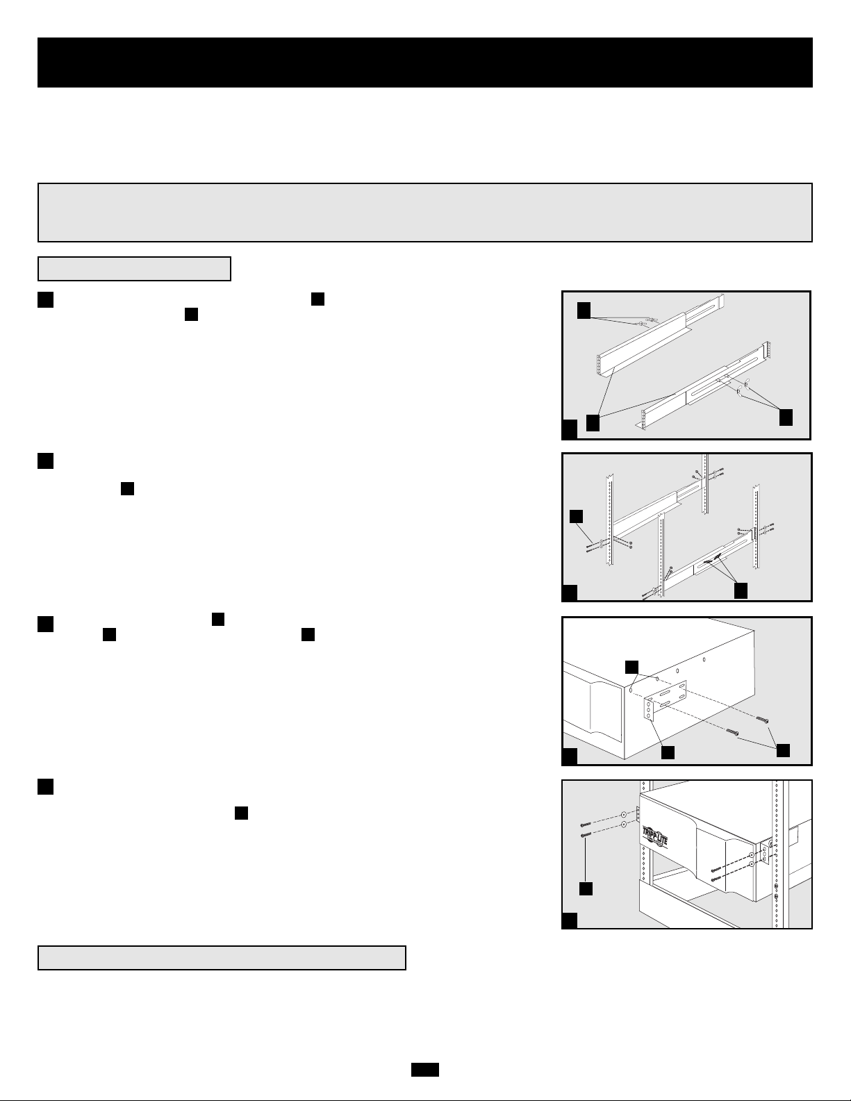
29
Montaje (Bastidor)
1
Montaje de 4 postes
1
2
3
A
B
C
F
E
G
4
H
Conecte los dos segmentos de cada anaquel usando los tornillos incluidos y las
tuercas de mariposa . Deje los tornillos ligeramente flojos de modo que los
anaqueles puedan ajustarse en el siguiente paso.
Ajuste cada anaquel para que se acomode a su bastidor y luego instálelo en el espacio
más bajo disponible del bastidor con los tornillos, las tuercas y las arandelas suministradas . Note que los bordes de apoyo deben mirar hacia adentro. Apriete las
tuercas de mariposa que conectan los segmentos de los anaqueles.
Fije las orejas de montaje a los agujeros de montaje de la parte delantera de su
equipo usando los tornillos suministrados . Las orejas deben mirar hacia adelante.
Con la ayuda de otra persona levante su equipo y deslícelo en los anaqueles de
montaje. Fije su equipo al bastidor pasando los tornillos, las tuercas y las arandelas
(suministradas por el usuario) a través de las orejas de montaje y dentro de los
rieles del bastidor.
Para montar su equipo en un bastidor de 2 postes, debe comprar un kit de instalación
para montaje en bastidor de 2 postes (modelo: 2POSTRMKIT, vendido por separado)
para cada módulo instalado. Consulte el manual del propietario del kit de instalación
para obtener completas instrucciones de montaje.
H
GF
E
C
B
A
4
Monte su equipo en un bastidor o en una caja de bastidor de 2 o 4 postes. El usuario debe determinar la idoneidad de los materiales y accesorios así como de los procedimientos antes del montaje. Si los materiales y procedimientos no son adecuados para su aplicación, contacte
con el fabricante de su bastidor. Los procedimientos descritos en este manual son para bastidores y cajas de bastidores comunes y podrían
no ser apropiados para todas las aplicaciones.
¡ADVERTENCIA!
¡Todos los módulos de no-break son muy pesados! ¡Tenga cuidado al levantarlos y montarlos! ¡El usuario debe
estabilizar apropiadamente el módulo al levantarlo y montarlo!
2
3
Montaje de 2 postes (Telecomunicaciones)
B
D
Page 30
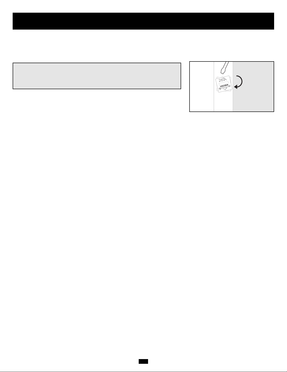
30
Montaje (en torre)
Todos los módulos pueden montarse en posición vertical, de torre, cuando se emplean con bases de soporte ajustables opcionales, vendidas
por separado por Tripp Lite (modelo #: 2-9USTAND). Al montar módulos en las bases de soporte ajustables asegúrese que el panel de control del módulo de potencia esté hacia la parte superior. Además, si está instalando un módulo de transformador, colóquelo entre el módulo
de potencia y su módulo de batería.
¡ADVERTENCIA!
¡Todos los módulos de no-break son muy pesados! ¡Tenga cuidado al
levantarlos y montarlos! ¡El usuario debe estabilizar apropiadamente el
módulo al levantarlo y montarlo!
Gire el panel de control del módulo de potencia para obtener mejor visibilidad mientras
el UPS esté montado en torre. Introduzca un pequeño destornillador u otra herramienta
en las ranuras en cualquier lado del panel de control. Saque el panel, gírelo y colóquelo
en posición nuevamente.
Page 31

31
Características
Hay tres módulos separados del sistema UPS disponibles de Tripp Lite (módulo de potencia, módulo de transformador y módulo de batería)
usados en varias combinaciones. Familiarícese con la ubicación y función de cada módulo antes de instalar y operar su sistema UPS. El
módulo de potencia es el único que incluye funciones del panel frontal.
Controles del panel frontal del módulo de potencia
1. PANTALLA LCD: Esta pantalla de matriz de puntos retroiluminada (16 × 2 caracteres) indica una amplia gama de condiciones de
operación y datos de diagnóstico del UPS. También muestra la configuración y las opciones del UPS durante el modo de configuración.
2. BOTÓN ON/MUTE: Presione y mantenga presionado este botón hasta escuchar un pitido para encender el inversor del UPS. Si la alarma
de batería del UPS está sonando, presione este botón para silenciarla.
3. BOTÓN DESPLAZAR HACIA ABAJO/SALIR DE CONFIGURACIÓN: Este botón le permite desplazarse a través de diferentes
opciones y lecturas de potencia en la pantalla LCD. Presionándolo momentáneamente, hace que la pantalla LCD muestre una lectura de
potencia diferente (vea “Operación”) Presionándolo junto con el botón DESPLAZAR HACIA ARRIBA, pone al UPS en modo de configuración, donde este botón se usa para desplazarse a través de las opciones y salir del modo de configuración.
4. BOTÓN DESPLAZAR HACIA ARRIBA/SELECT: Este botón le permite desplazarse a través de diferentes opciones y lecturas de
potencia en la pantalla LCD. Presionándolo momentáneamente hace que la pantalla LCD muestre una lectura de potencia diferente (vea
“Operación”) Presionándolo junto con el botón DESPLAZAR HACIA ABAJO, pone al UPS en modo de configuración, donde este
botón se usa para seleccionar opciones de configuración.
5. BOTÓN OFF: Presione este botón hasta que escuche un pitido para apagar el inversor del UPS.
6. LED O/P (SALIDA): Esta luz verde se encenderá para indicar que su UPS está suministrando energía de corriente alterna al equipo conectado.
7. LED DC/AC (INVERSOR): Esta luz verde se encenderá para indicar que el inversor de corriente continua a corriente alterna del UPS
está activado.
8. LED BYPASS: Esta luz verde se encenderá cuando el UPS esté proporcionando energía filtrada desde la red sin emplear su convertidor
o inversor. Si este LED está encendido, el equipo conectado no recibirá energía de batería en caso de una falla del servicio eléctrico.
9. LED AC/DC (Convertidor): Esta luz verde se encenderá para indicar que el convertidor de corriente alterna a corriente continua del
UPS está cargando los bancos de baterías conectados.
10. LED BATTERY: Esta luz roja se encenderá cuando el UPS esté descargando la batería para proporcionar energía de corriente alterna al
equipo conectado. Sonará una alarma, la que puede ser silenciada presionando el botón ON/MUTE. Este LED permanecerá encendido
después de que la alarma haya sido silenciada.
11. LED I/P (ENTRADA): Esta luz verde se encenderá para indicar que existe un suministro de alimentación de corriente alterna.
12. RANURAS DE ACCESO: Para girar los controles, introduzca un destornillador plano en estas ranuras y palanquee suavemente el
panel hacia afuera. Con cuidado de no torcer o tirar excesivamente de los cables que conectan los controles al resto del UPS, gire los
controles hasta la orientación deseada y introdúzcalos nuevamente.
1
2 345
6879
10
11
12
12
Page 32

32
Características (Panel posterior)
Vea una descripción de las características en la página 35
Módulo de potencia de 5 kVA
Módulo de transformador de 5 kVA
Módulo de batería de 5 kVA*
* El módulo de potencia de 5 kVA se despacha con un módulo de
batería no extensible; sin embargo, el módulo de potencia es
totalmente compatible con los módulos de baterías extensibles de
Tripp Lite (Tripp Lite modelo # BP240V10RT-3U, vendido por
separado) si se requiere tiempo de respaldo extendido.
11
6
7
89
10
3
12
12
13
13
14
25
25
24 26 24
25
25
28
Page 33

33
Características (Panel posterior)
Vea una descripción de las características en la página 35
Módulo de potencia de 6 kVA
Módulo de transformador de 6 kVA
Módulo de batería para modelo de 6 kVA*
54
6
7
89
10
20
20
19
16
27
28
3
1 2
15
17
22
23
* Módulo de batería extensible (Tripp Lite modelo #
BP240V10RT-3U) mostrado. Según el modelo ordenado, el
módulo de potencia de 6 kVA puede despacharse con un
módulo de batería extensible (como el mostrado arriba) o no
extensible. Sin embargo, todos los módulos de potencia de 6
kVA, son totalmente compatibles con el módulo de baterías
BP240V10RT-3U (vendido por separado) si se requiere tiempo de respaldo extensible.
Page 34

34
Características (Panel posterior)
Vea una descripción de las características en la página 35
Módulo de potencia de 10 kVA
Módulo de batería para modelo de 10 kVA*
Módulo de transformador de 10 kVA
45
6
7
8
9
10
3
27
28
20
18
15
16
21
12
19
22 23
* Módulo de batería extensible (Tripp Lite modelo #
BP240V10RT-3U) mostrado. Según el modelo ordenado, el
módulo de potencia de 10 kVA puede despacharse con un
módulo de batería extensible (como el mostrado arriba) o no
extensible. Sin embargo, todos los módulos de potencia de 10
kVA, son totalmente compatibles con el módulo de baterías
BP240V10RT-3U (vendido por separado) si se requiere tiempo de respaldo extensible.
Page 35

35
Características (Panel)
(continuación)
Descripción de características del módulo de potencia
1. Bloque de terminales de salida (Sólo en modelos de 6 kVA y 10 kVA): Use estos terminales para conectar su módulo de potencia a
su equipo o al módulo del transformador. Destornille y retire la cubierta del bloque para tener acceso.
2. Bloque de terminales de entrada (Sólo en modelos de 6 kVA y 10 kVA): Use estos terminales para conectar su módulo de potencia
a la alimentación de la red o al módulo del transformador. Destornille y retire la cubierta del bloque para tener acceso.
3. Conector de batería externa: Úselo para conectar uno o más módulos de batería de Tripp Lite al módulo de potencia. Retire la cubierta
para tener acceso. El módulo de potencia no arrancará sin una conexión a un módulo de batería cargada. Consulte el manual del
propietario del módulo de batería para obtener instrucciones sobre conexión y advertencias de seguridad.
4. Interruptor automático de entrada de CA (Sólo en modelos de 6 kVA y 10 kVA): Un interruptor automático bipolar controla la
entra da de energía al módulo de potencia.
5. Interruptor automático de salida de CA (Sólo en modelos de 6 kVA y 10 kVA): Un interruptor automático bipolar controla la
salida de energía del módulo de potencia.
6. Ventilador extractor: Enfría y ventila el interior del módulo de potencia.
7. Ranura auxiliar: Retire el pequeño panel de cubierta para instalar accesorios opcionales para el control y monitoreo de su UPS en forma remota.
Visite Tripp Lite en la web (www.tripplite.com) para conocer sobre los productos SNMP, de administración de redes y de conectividad
que pueden instalarse en esta ranura.
8. Puerto EPO (Desconexión de emergencia): El módulo de potencia tiene un puerto EPO que puede usarse para conectar el módulo
de potencia a un interruptor de cierre de contacto que permita el apagado de emergencia. Consulte la sección “Conexión opcional” para
más detalles.
9. Puerto de comunicaciones RS-232: Este puerto serie DB9 hembra puede usarse para conectar su UPS a una estación de trabajo o a
un servidor. Usa el protocolo RS-232 para comunicarse con una computadora conectada. Se emplea con el software de Tripp Lite y el
cable serie incluido para monitorear y administrar el UPS en forma remota en una red y para guardar automáticamente los archivos
abiertos y apagar el equipo durante una falla del servicio eléctrico. Consulte la sección “Conexión opcional” para más detalles.
10. Puerto de interfaz de contacto seco: Este puerto DB9 hembra envía señales de cierre de contacto para indicar una falla en la línea y
un estado de batería baja. Consulte la sección “Conexión opcional” para más detalles.
11. Interruptor de CA Output 1 (sólo en modelos de 5 kVA): Un interruptor automático bipolar controla la potencia de salida de las
tomas de CA del módulo de potencia de 5 kVA rotuladas "Output 1."
12. Tomas de CA Output 1 (sólo en modelos de 5 kVA): Acepta conexión directa de enchufes de equipo NEMA L6-20P.
13. Tomas de CA Output 2 (sólo en modelos de 5 kVA): Acepta conexión directa de enchufes de equipo NEMA L6-30P. Cualquier toma
también acepta la conexión directa del cable de conector de transformador (si se emplea).
14. Cordón de entrada de CA (sólo en modelos de 5 kVA): Conecta directamente a una toma de pared, proporcionando 200/208/220/230
o 240 VCA de energía de la red.
Descripción de características del módulo del transformador
15. Bloque de terminales de entrada de la red (Sólo en modelos de 6 kVA y 10 kVA): Use estos terminales para conectar su módulo de
transformador a la energía de la red. Destornille y retire la cubierta del bloque para tener acceso.
16. Bloque de terminales de salida de equipo (Sólo en modelos de 6 kVA y 10 kVA): Use estos terminales para conectar su equipo al
módulo de transformador. Destornille y retire la cubierta del bloque para tener acceso.
17. Cable para conexión de módulo de potencia (sólo en modelos de 6 kVA): Conecta el módulo de transformador a la entrada/salida del
módulo de potencia después que el bloque de terminales del módulo de potencia ha sido retirado. Consulte la sección “Conexión” para
más detalles.
18 Bloque de terminales cableados para conexión del módulo de potencia (sólo en modelos de 10 kVA): Use estos terminales para
conectar el módulo de transformador a los bloques de terminales de entrada y salida del módulo de potencia. Consulte la sección
“Conexión” para más detalles.
19. Interruptor de reposición de sobretemperatura (Sólo en modelos de 6 kVA y 10 kVA): Este interruptor dispara si la temperatura
de la unidad aumenta demasiado.
20. Interruptor automático de CA a UPS (Sólo en modelos de 6 kVA y 10 kVA): Un interruptor automático bipolar controla la salida de
potencia del módulo de transformador al UPS.
21. Interruptor de salida (Sólo en modelos de 6 kVA y 10 kVA): Un interruptor automático tripolar controla la salida de potencia del
módulo de transformador al equipo conectado.
22. Interruptor de derivación manual (Sólo en modelos de 6 kVA y 10 kVA): Este dial rojo y amarillo se emplea para poner en derivación
(bypass) el módulo de potencia mientras sigue dando soporte al equipo conectado cuando se realiza mantenimiento al módulo de potencia.
Mientras este interruptor está en BYPASS, el equipo conectado recibirá energía de CA filtrada de la red del módulo del transformador,
pero el equipo no recibirá energía de batería en caso de una falla del servicio eléctrico. Consulte todo el procedimiento de derivación en
la sección “Operación de derivación manual”.
Page 36

36
Descripción de características del módulo de batería
27. Conector de entrada (Sólo módulos exclusivos de baterías): Use este conector para encadenar módulos de batería adicionales con el
primero. Retire el panel de cubierta para tener acceso. Consulte el manual del propietario del módulo de batería para obtener instrucciones
sobre conexión y advertencias de seguridad.
28. Cable de salida: Use este cable para conectar el módulo de batería al módulo de potencia en otro módulo de batería. El módulo de
potencia no arrancará sin una conexión a un módulo de batería cargada. Consulte el manual del propietario del módulo de batería para
obtener instrucciones sobre conexión y advertencias de seguridad.
¡ADVERTENCIA! Sólo para personal de servicio calificado. Si no sigue el procedimiento de derivación por
completo, no apagará adecuadamente el módulo de potencia del UPS, produciendo un permanente riesgo de
muerte o lesiones debido a un contacto potencial con alto voltaje.
23. Interruptor selector de voltaje (Sólo en modelos de 6 kVA y 10 kVA): Use este interruptor para determinar el voltaje de entrada
del módulo del transformador (200, 208 o 240 VCA) Consulte la sección “Conexión” para más detalles.
24. Tomas de CA de salida (sólo en modelos de 5 kVA): Acepta conexión directa de enchufes de equipo NEMA 5-15P o NEMA 5-20P.
25. Interruptores automáticos de CA (sólo en modelos de 5 kVA): Interruptores pulsadores controlan la potencia de salida a las tomas
de salida de CA del módulo del transformador directamente adyacentes.
26. Cable para conexión de módulo de potencia (sólo en modelos de 5 kVA): Se conecta directamente en cualquiera de las tomas de
CA rotuladas "Output 2" del módulo de potencia de 5 kVA. NOTA: Este cable sólo debe conectarse en el módulo de potencia de
5 kVA.
Características (Panel)
(continuación)
Conexión
• El cableado debe ser realizado por un electricista calificado.
• El módulo de potencia del UPS puede estar instalado sólo o conectado a un módulo de transformador de aislamiento. Ambas aplicaciones requieren
que el módulo de potencia esté conectado a un módulo de batería.
• Al realizar conexiones del cableado, siempre cumpla las reglamentaciones adecuadas para conexión de cables de su área [por ejemplo, el Código
Eléctrico Nacional (NEC) en EE.UU.]. Asegúrese de instalar un interruptor de desconexión fácilmente accesible en su cableado de modo que pueda
cortar la entrada de corriente alterna al UPS durante incendios y otras emergencias. Asegúrese que los cables estén dotados de mangas y asegurados
por abrazaderas de conectores. Apriete las conexiones con un torque no menor que 24-28 libras-pulgada (2.7-3.2 Nm)
• Asegúrese que su equipo esté puesto a tierra adecuadamente.
• El uso de cables de calibre inadecuado puede dañar su equipo y causar riesgos de incendio. Elija los cables y circuitos de protección adecuados
para realizar las conexiones del cableado (Los conductores de tierra deben ser del mismo tipo y calibre que los conductores de energía utilizados):
CORRIENTE DE ENTRADA CORRIENTE DE SALIDA CORRIENTE DE SALIDA
200 - 240 (1Ø, 2 cond. + 200 - 240 V (1Ø, 2 cond. + 120 V (1Ø, 2 cond. + CIRCUITO DE PROTECCIÓN
forro de polietileno) forro de polietileno) forro de polietileno) DE SALIDA
Modelos de 6 kVA 30A 8 AWG (10 mm2) 30A 8 AWG (10mm2) 2 × 30A 8 AWG (10mm2) 30A
Modelos de 10 kVA 50A 6 AWG (16mm2) 50A 6 AWG (16mm2) 2 × 50A 6 AWG (16mm2) 63A
Precauciones del cableado
(Sólo en modelos de 6 kVA y 10 kVA)
Conexión de módulos entre sí, a la energía de la red y a equipos
Hay tres módulos separados del UPS disponibles de Tripp Lite (un módulo de potencia y un módulo de batería, que son necesarios en todas
las aplicaciones, y un módulo de transformador) usados en diferentes combinaciones. Siga el procedimiento de conexión indicado a continuación de acuerdo con la combinación de módulos que planea instalar.
Page 37

37
Combinación de conexión #1
Módulo de potencia (5 kVA) + módulo de batería
Conecte su equipo en el módulo de potencia.
Conecte los cordones de alimentación de su equipo directamente en las
tomas de salida de CA . del módulo de potencia.
Conecte el módulo de potencia en una toma de
corriente de pared.
Conecte el cordón de entrada de CA del módulo de potencia directamente
en una toma de pared proporcionando 200/208/220/230 o 240VCA de
energía de la red.
Conecte el módulo de batería al módulo de potencia.
Consulte el manual del propietario incluido con su módulo de batería.
Introduzca completamente el conector del extremo del cable del módulo de
batería en el conector de la parte posterior del módulo de potencia .
Pueden producirse pequeñas chispas; esto es normal. NOTA: El módulo de
potencia no contiene baterías internas y no arrancará si no tiene conectado un
módulo de batería. Los módulos de batería son completamente cargados antes
de despacharse. Sin embargo, antes de esperar una completa capacidad de
respaldo (en particular, si el módulo de batería ha estado almacenado por un
período prolongado) después de conectar el no-break a una fuente de energía
de la red, permita que el módulo de batería se recargue 12 horas. Luego que
el no-break esté en uso, cargará las baterías y mantendrá el nivel de carga
automáticamente. NOTA: El módulo de potencia de 5 kVA se despacha con
un módulo de batería no extensible; sin embargo, el módulo de potencia es
totalmente compatible con los módulos de baterías extensibles de Tripp Lite
(Tripp Lite modelo # BP240V10RT-3U, vendido por separado) si se requiere
tiempo de respaldo extendido.
FE
D
C
B
A
1
2
2
3
3
A
B
C
E
F
1
D
Conexión
(continuación)
Page 38
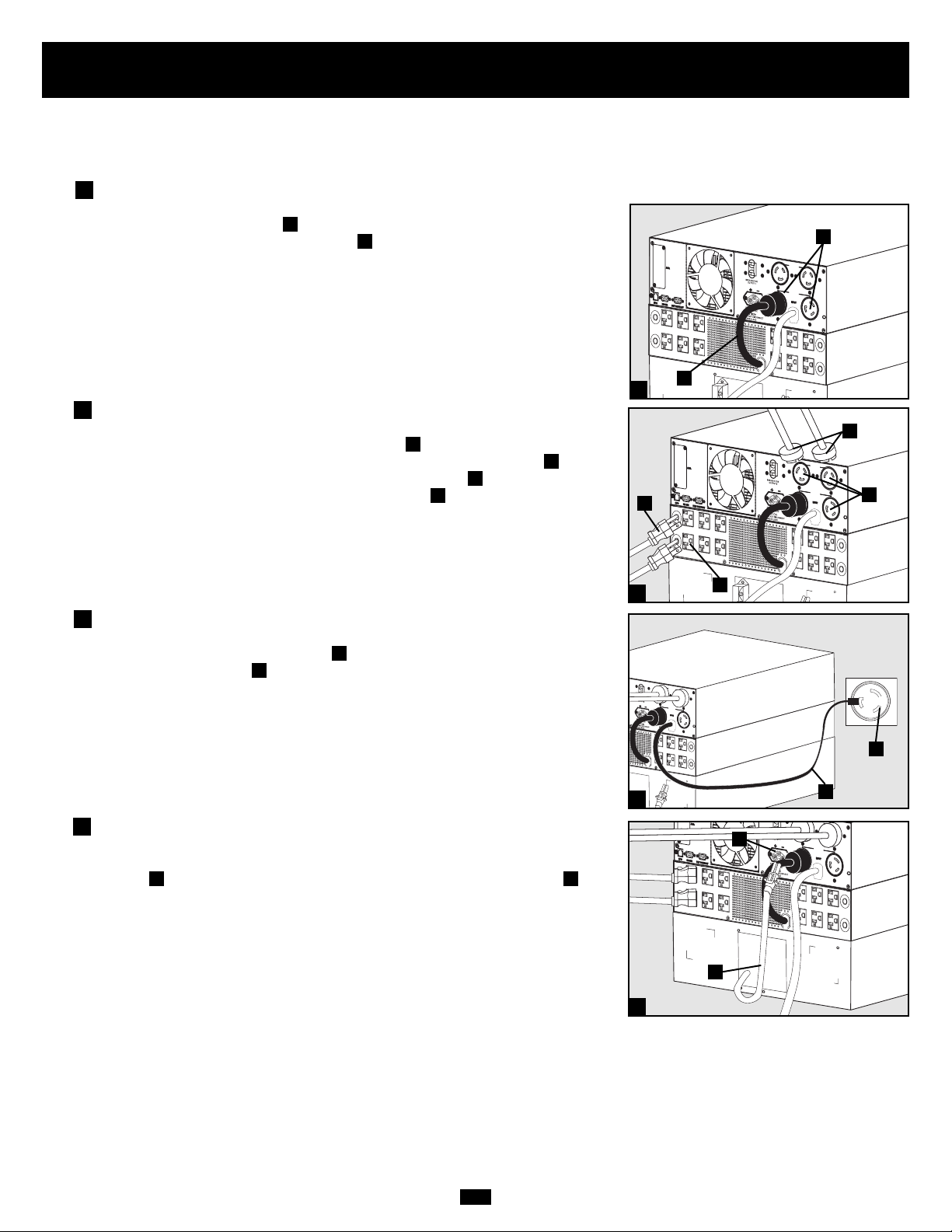
38
Conexión
(continuación)
Combinación de conexión #2
Módulo de potencia (5kVA) + módulo de transformador (5 kVA) + módulo de batería
Conecte el módulo de transformador en el módulo
de potencia.
Conecte el cable del conector del módulo del transformador directamente en
cualquiera de las tomas de CA "Output 2" del módulo de potencia de 5 kVA.
NOTA: Este cable sólo debe conectarse en el módulo de potencia de 5 kVA.
Conecte su equipo en el módulo de potencia y el
módulo de transformador.
Conecte los cordones de alimentación de sus equipos de
200/208/220/230/240 VCA directamente en las tomas de salida de CA del
módulo de potencia. Conecte los cordones de alimentación de su equipo de
120 VCA directamente en las tomas de salida de CA del módulo del transformador.
Conecte el módulo de potencia en una toma de
corriente de pared.
Conecte el cordón de entrada de CA del módulo de potencia directamente
en una toma de pared proporcionando 200/208/220/230 o 240VCA de
energía de la red.
Conecte el módulo de batería al módulo de potencia.
Consulte el manual del propietario incluido con su módulo de batería.
Introduzca completamente el conector del extremo del cable del módulo de
batería en el conector de la parte posterior del módulo de potencia .
Pueden producirse pequeñas chispas, lo que es normal. NOTA: El módulo de
potencia no contiene baterías internas y no arrancará si no tiene conectado un
módulo de batería. Los módulos de batería están completamente cargados
antes de despacharse. Sin embargo, antes de esperar una completa capacidad
de respaldo (en particular si el módulo de batería ha estado almacenado por
un período prolongado) después de conectar el no-break a una fuente de alimentación de la red, permita que el módulo de batería se recargue 12 horas.
Luego que el no-break esté en uso, cargará las baterías y mantendrá el nivel
de carga automáticamente. NOTA: El módulo de potencia de 5 kVA se
despacha con un módulo de batería no extensible; sin embargo, el módulo de
potencia es totalmente compatible con los módulos de baterías extensibles de
Tripp Lite (Tripp Lite modelo # BP240V10RT-3U, vendido por separado) si
se requiere tiempo de respaldo extendido.
JI
H
G
F
E
D
C
B
A
1
2
2
3
3
A
B
E
H
G
1
4
4
F
D
C
I
J
Page 39

39
Combinación de conexión #3: Módulo de potencia
(de 6 kVA o 10 kVA) + Módulo(s) de batería
Cablee el módulo de potencia a su equipo.
Con un destornillador, retire la parte superior de la caja que cubre los terminales
de entrada y salida del módulo de potencia. Pase un cable suministrado por el
usuario a través del agujero ciego izquierdo de la caja de terminales y
conéctelo a los terminales de salida del módulo de potencia. Conecte el otro
extremo del cable a su equipo.
Cablee el módulo de potencia a una fuente de energía
de la red.
Pase un cable suministrado por el usuario a través del agujero ciego derecho
y conéctelo a los terminales de entrada del módulo de potencia. Coloque
nuevamente la tapa de la caja de terminales. Conecte el otro extremo del cable
a una fuente de energía de la red.
Conecte el módulo de batería al módulo de potencia.
Consulte el manual del propietario incluido con su módulo de batería.
Introduzca completamente el conector del extremo del cable del módulo de
batería en el conector de la parte posterior del módulo de potencia .
Pueden producirse pequeñas chispas; esto es normal. NOTA: El módulo de
potencia no contiene baterías internas y no arrancará si no tiene conectado un
módulo de batería. Los módulos de batería están completamente cargados
antes de despacharse. Sin embargo, antes de esperar una completa capacidad
de respaldo (en particular si el módulo de batería ha estado almacenado por
un período prolongado) después de conectar el UPS a una fuente de energía
de la red, permita que el módulo de batería se cargue 12 horas. Luego de que
el sistema UPS esté en uso, cargará las baterías y mantendrá el nivel de carga
automáticamente. Si es necesario, conecte módulos de baterías adicionales
encadenados, con el cable de cada módulo introducido en el conector del
módulo anterior.
F
ED
C
B
A
1
2
2
3
3
A
B
C
D
E
F
1
Módulo de potencia de 6 kVA mostrado
Conexión
(continuación)
Page 40

40
Combinación de conexión #4: Módulo de potencia (6 kVA) +
Módulo de transformador (6 kVA) + Módulo(s) de batería
Conecte el módulo de potencia al módulo
de transformador.
Con un destornillador, retire la parte superior de la caja que cubre los terminales
de entrada y salida del módulo de potencia. Retire los tornillos en cualquier
lado de los terminales. Tome los terminales y deslícelos hacia afuera hasta
que pueda ver la lengüeta de desenganche del conector del cable. Presione la
lengüeta hacia abajo y tire de los cables para soltarlos del conector interno .
Retire los terminales. Introduzca el cable del conector del módulo de transformador
en los conectores internos en la caja de terminales del módulo de potencia
hasta que la lengüeta haga clic. Coloque nuevamente los tornillos alrededor de
la placa. Aunque no son necesarios, conserve los terminales y la cubierta de la
caja de terminales del módulo de potencia en caso que planee operar el módulo
de potencia sin el módulo de transformador posteriormente.
Cablee el módulo de transformador a su equipo.
Con un destornillador, retire la parte superior de la caja que cubre los terminales
de entrada y salida del módulo de transformador. Pase un cable suministrado
por el usuario a través del agujero ciego izquierdo de la caja y conéctelo a
los terminales de salida del módulo de transformador. Vea el Diagrama de
voltaje de salida de CA para determinar las conexiones de terminales que
proporcionarán el voltaje adecuado a su aplicación. Conecte el otro extremo
del cable a su equipo.
Cablee el módulo de transformador a una fuente
de energía de la red.
Pase un cable suministrado por el usuario a través del agujero ciego derecho de
la caja y conéctelo a los terminales de entrada del módulo de transformador.
Coloque nuevamente la parte superior de la caja que cubre los terminales del
módulo de transformador. Conecte el otro extremo del cable a una fuente de
energía de la red.
I
H
G
F
E
D
C
B
A
1
1
3
Conexión
(continuación)
2
2
3
1
A
B
C
E
G
I
F
Combinación de conexión #4 (continúa en página siguiente)
H
D
N
O
R
M
A
L
DIAGRAMA DE VOLTAJE DE SALIDA DE CA
120
208
V
240
V
V
120
V
G
BY
PAS
S
N
O
R
M
A
L
BY
PAS
S
N
O
R
M
A
L
BY
PAS
S
Page 41

41
Seleccione el voltaje de entrada del módulo
de transformador.
Usando un destornillador, retire el panel que cubre el interruptor selector de
voltaje del módulo de transformador . Fije el interruptor para que coincida
con el voltaje de entrada de su instalación. Luego, use los interruptores del
panel frontal del módulo de potencia para configurar el voltaje de entrada en
la pantalla LCD (consulte “Configuración de la entrada y salida de su UPS” en
la sección “Encendido y apagado”).
NOTA IMPORTANTE: Si el voltaje de entrada de su instalación es 200 VCA,
fije el interruptor del módulo de transformador a 240 VCA, pero configure el
módulo de potencia a 200 VCA. Si el voltaje de entrada de su instalación es
208 o 240 VCA, los ajustes del módulo de transformador y del módulo de
potencia deben coincidir. El ajuste predeterminado de fábrica para ambos
módulos es 208 V. Vea la tabla siguiente:
Módulo de potencia
Módulo de transformador Ajuste de voltaje de entrada
Voltaje de entrada Ajuste de voltaje de entrada (Interruptores/pantalla
de su instalación (Interruptor de panel posterior) LCD de panel frontal)
240 VCA 240 VCA 240 VCA
208 VCA 208 VCA 208 VCA
200 VCA 240 VCA 200 VCA
Conecte el módulo de batería al módulo de potencia.
Consulte el manual del propietario incluido con su módulo de batería.
Introduzca completamente el conector del extremo del cable del módulo de
batería en el conector de la parte posterior del módulo de potencia .
Pueden producirse pequeñas chispas; esto es normal. NOTA: El módulo de
potencia no contiene baterías internas y no arrancará si no tiene conectado un
módulo de batería. Los módulos de batería están completamente cargados antes
de despacharse. Sin embargo, antes de esperar una completa capacidad de respaldo
(en particular si el módulo de batería ha estado almacenado por un período prolongado) después de conectar el UPS a una fuente de energía de la red, permita que
el módulo de batería se cargue 12 horas. Luego de que el sistema UPS esté en
uso, cargará las baterías y mantendrá el nivel de carga automáticamente. Si es
necesario, conecte módulos de baterías adicionales encadenados, con el cable
de cada módulo introducido en el conector del módulo anterior.
Combinación de conexión #5: Módulo de potencia
(10 kVA) + Módulo de transformador (10 kVA)
+ Módulo(s) de batería
Cablee el módulo de potencia al módulo
de transformador
Con un destornillador, retire la parte superior de la caja que cubre los terminales
de entrada y salida del módulo de potencia. Coloque nuevamente la parte superior
de la caja que cubre los terminales del módulo de transformador. Con el
cable suministrado, conecte los terminales de entrada y salida del módulo de
potencia a los terminales correspondientes en el módulo del transformador
“Hardwire Terminal Block for Power Module Connection” en el agujero ciego
derecho de la caja .
C
B
A
M
LK
J
Conexión
(continuación)
4
5
5
1
1
4
J
M
L
A
B
C
K
Combinación de conexión #5 (continúa en página siguiente)
NORMAL
PAS S
BY
240V AC
208V AC
N
O
R
M
A
L
BY
PAS
S
NORMAL
BY
PAS
S
Page 42

42
Cablee el módulo de transformador a su equipo.
Pase un cable suministrado por el usuario a través del agujero ciego izquierdo de
la caja y conéctelo a los terminales de salida del módulo de transformador.
Vea el Diagrama de voltaje de salida de CA para determinar las conexiones
de terminales que proporcionarán el voltaje adecuado a su aplicación. Conecte
el otro extremo del cable a su equipo.
Cablee el módulo de transformador a una fuente
de energía de la red.
Pase un cable suministrado por el usuario a través del agujero ciego central de
la caja y conéctelo a los terminales de entrada del módulo de transformador.
Conecte el otro extremo del cable a una fuente de energía de la red. Coloque
nuevamente la parte superior de la cajas que cubren los terminales de los
módulos de potencia y del transformador.
Seleccione el voltaje de entrada del módulo
de transformador.
Usando un destornillador, retire el panel que cubre el interruptor selector de
voltaje del módulo de transformador . Fije el interruptor para que coincida
con el voltaje de entrada de su instalación. Luego, use los interruptores del
panel frontal del módulo de potencia para configurar el voltaje de entrada en
la pantalla LCD (consulte “Configuración de la entrada y salida de su UPS” en
la sección “Encendido y apagado” en la página 36).
NOTA IMPORTANTE: Si el voltaje de entrada de su instalación es 200 VCA,
fije el interruptor del módulo de transformador a 240 VCA, pero configure el
módulo de potencia a 200 VCA. Si el voltaje de entrada de su instalación es
208 o 240 VCA, los ajustes del módulo de transformador y del módulo de
potencia deben coincidir. El ajuste predeterminado de fábrica para ambos
módulos es 208 V. Vea la tabla siguiente:
Módulo de transformador Módulo de potencia
Ajuste de voltaje de Ajuste de voltaje de entrada
Voltaje de entrada entrada (Interruptor de (Interruptores/pantalla
de su instalación panel posterior) LCD de panel frontal)
240 VCA 240 VCA 240 VCA
208 VCA 208 VCA 208 VCA
200 VCA 240 VCA 200 VCA
Conecte el módulo de batería al módulo de potencia.
Consulte el manual del propietario incluido con su módulo de batería.
Introduzca completamente el conector del extremo del cable del módulo de
batería en el conector de la parte posterior del módulo de potencia .
Pueden producirse pequeñas chispas; esto es normal. NOTA: El módulo de
potencia no contiene baterías internas y no suministrará energía al equipo
conectado si no tiene conectado un módulo de batería. Los módulos de batería
están completamente cargados antes de despacharse. Sin embargo, si el módulo de batería ha estado almacenado por un período prolongado, después de
conectar el UPS a una fuente de energía de la red, permita que el módulo de
batería se cargue durante 12 horas. Si es necesario, conecte módulos de
baterías adicionales encadenados, con el cable de cada módulo introducido en
el conector del módulo anterior.
J
IH
G
F
E
D
3
3
4
5
5
F
4
H
I
J
Conexión
(continuación)
2
D
E
2
G
DIAGRAMA DE VOLTAJE DE SALIDA DE CA
120
208
V
240
V
V
120
V
G
PAS S
240V AC
BY
208V AC
NORMAL
N
O
R
M
A
L
BY
PA
SS
N
O
R
M
A
L
BY
PAS
S
N
O
R
M
A
L
BY
PAS
S
Page 43

43
Las siguientes conexiones son opcionales. Su UPS funcionará correctamente sin ellas.
Conexión de comunicación serie RS-232
Use el cable incluido para conectar el puerto “RS-232” del módulo de potencia con el
puerto de comunicaciones en su PC. Esto permitirá un monitoreo de toda la red y el
control de su sistema UPS. Instale en su computadora el software PowerAlert de Tripp
Lite apropiado para su sistema operativo.
Conexión de comunicaciones de cierre de contacto
Use un cable DB9 de cierre de contacto suministrado por el usuario para conectar el
puerto de contacto seco del módulo de potencia al puerto de comunicaciones de su PC
u otro equipo. Esto permitirá enviar señales básicas de cierre de contacto al y del UPS.
Consulte el siguiente diagrama y la tabla para determinar las señales transportadas por
este puerto. Instale en su computadora el software PowerAlert de Tripp Lite apropiado
para su sistema operativo.
Conexión de puerto EPO
Esta característica opcional es sólo para aquellas aplicaciones que requieran una conexión
al circuito de desconexión de emergencia (EPO) de la instalación. Cuando el módulo de
potencia está conectado a este circuito, es posible el apagado de emergencia de la salida.
Usando el cable incluido, conecte el puerto EPO del módulo de potencia a un interruptor
remoto suministrado por el usuario. La asignación de los pines para el puerto EPO se
muestra en el diagrama siguiente. Nota: Si hay un corto entre los pines 2 y 3, 2 y 5, 4 y 5,
o 3 y 4, el sistema UPS se apagará.
Conexión opcional
DIAGRAMA DE INTERFAZ DE CONTACTO SECO
Modo de Pin 8,3 Pin 1,3 Pin 6,3
operación
del UPS
Normal ABIERTO ABIERTO *
Respaldo CERRADO * *
Batería baja CERRADO CERRADO *
Falla * * CERRADO
Inactivo: Puede estar en cualquier estado
TABLA DE INTERFAZ DE CONTACTO SECO
ASIGNACIÓN DE PINES EPO
lm in. > 3.3 mA
BATERÍA BAJA
NO
COM NC
CAPACIDAD MÁXIMA DE CONTACTO SECO: CA 250V/3A. CC 30V/3A
54321
9
8
7
SEÑAL DE COMPUTADORA
RESPALDO
COM NC
6
NO
SEÑAL EXTERNA PARA
APAGADO REMOTO
>2 sec
12 V
0
12V
X
1K
X
1
2
3
4
5
6
Page 44

44
Encendido y apagado (sólo en modelos de 5 kVA)
1. Configure la entrada y salida del UPS: Ponga el módulo de potencia del UPS en modo de configuración manteniendo presionados
simultáneamente ambos botones de desplazamiento ( y ). Puede desplazarse por las opciones de configuración (usando o ) y
seleccionar el ajuste adecuado para cada una de las siguientes opciones usando el botón “SELECT” .
• Voltaje de entrada y salida: Seleccione 200, 208 o 240 VCA.
• Frecuencia de salida: Su UPS seleccionará automáticamente 50 o 60 Hz para que corresponda a la frecuencia de entrada.
• Modo Economy (Economía): Su UPS puede proporcionar operación en línea con un tiempo de transferencia cero. También
puede operar en un modo interactivo con la línea con mayor eficiencia de energía
• Active el modo Economy para poner al UPS en modo interactivo con la línea. Desactive el modo Economy para poner el UPS
en modo en línea.
• Después de haber fijado estas opciones, “salga” del modo de configuración con el botón de desplazamiento , y salga del modo
Bypass manteniendo presionado el botón ON hasta que escuche un pitido.
2. Encienda la entrada al no-break: Presione y mantenga presionado el botón ON del módulo de potencia hasta que escuche un piti-
do para arrancar su no-break en modo ON BATTERY. Note que ciertos equipos electrónicos pueden consumir más corriente durante el
arranque; al arrancar con batería, considere reducir la carga inicial al no-break. Su no-break realizará una breve auto-prueba y mostrará
los resultados en la pantalla LCD . Consulte "Auto-prueba de arranque" en la sección "Operación" para conocer la secuencia en pantalla.
3. Para apagar el módulo de potencia y el módulo del transformador (si se emplea) del no-break: Presione el botón OFF del módu-
lo de potencia hasta que escuche un pitido. Su carga todavía estará energizada. El inversor ahora está apagado, pero su no-break no está
completamente desactivado. La pantalla LCD indicará BYPASS MODE. Apague el interruptor automático de la salida del módulo de potencia. Desconecte el cordón de alimentación de CA del módulo de potencia de la toma de corriente de pared. Si se emplea un
módulo de transformador, desconecte su cable conector del módulo de potencia. Su carga ya no estará energizada y la pantalla LCD (D)
no estará iluminada.
ED
F
D
C
C
A
B
BABA
Modelo de 5 kVA
D
C
A
B F
E
Modelo de 5 kVA
(Panel frontal)
Page 45

45
1. Configure la entrada y salida del UPS: Ponga el módulo de potencia del UPS en modo de configuración manteniendo presionados
simultáneamente ambos botones de desplazamiento ( y ). Puede desplazarse por las opciones de configuración (usando o ) y
seleccionar el ajuste adecuado para cada una de las siguientes opciones usando el botón “SELECT” .
• Voltaje de entrada y salida: Seleccione 200, 208 o 240 VCA.
• Frecuencia de salida: Su UPS seleccionará automáticamente 50 o 60 Hz para que corresponda a la frecuencia de entrada.
• Modo Economy (Economía): Su UPS puede proporcionar operación en línea con un tiempo de transferencia cero. También
puede operar en un modo interactivo con la línea con mayor eficiencia de energía
• Active el modo Economy para poner al UPS en modo interactivo con la línea. Desactive el modo Economy para poner el UPS
en modo en línea.
• Después de haber fijado estas opciones, “salga” del modo de configuración con el botón de desplazamiento , y salga del modo
Bypass manteniendo presionado el botón ON hasta que escuche un pitido.
2. Encienda la entrada al UPS: Si el módulo de potencia del UPS está conectado a un módulo de transformador, encienda los interruptores
automáticos CA-a-UPS y de salida del circuito del módulo del transformador. Encienda el interruptor automático de entrada del
módulo de potencia. Presione el botón ON del módulo de potencia hasta que escuche un pitido para comenzar la operación del inversor.
Si su entrada de CA no está proporcionando energía en forma normal, puede “arrancar en frío” su UPS con la batería. (Su batería debe
estar cargada por lo menos parcialmente para que esta operación tenga resultado) Presione y mantenga presionado el botón “ON” hasta
que escuche un pitido para arrancar su UPS en modo ON BATTERY. Note que ciertos equipos electrónicos pueden consumir más corriente durante el arranque; al arrancar con batería, considere reducir la carga inicial al UPS. Su UPS realizará una breve auto-prueba y
mostrará los resultados en la pantalla LCD . Consulte “Auto-prueba de arranque” en la sección “Operación” para conocer la secuencia
en pantalla.
3. Encienda la salida del UPS: Encienda el interruptor automático de salida del módulo de potencia del UPS. Si el UPS está conectado
a un módulo transformador, cambie el Interruptor de derivación manual del módulo de transformador de BYPASS a NORMAL y
encienda su interruptor automático de salida. Ahora su UPS proporcionará energía al equipo conectado.
4. Para apagar el módulo de potencia y el módulo de transformador del UPS: Presione el botón OFF del módulo de potencia del
UPS hasta que escuche un pitido. Su carga todavía estará energizada. El inversor ahora está apagado, pero su UPS no está completamente
desactivado. La pantalla LCD indicará BYPASS MODE. Apague los interruptores automáticos de entrada y salida ( y ) del módulo
de potencia del UPS. Si el UPS está conectado a un módulo de transformador, apague los interruptores automáticos de alimentación CAa-UPS y de salida del circuito del módulo del transformador . Su carga ya no estará energizada, y la pantalla LCD no estará iluminada.
FD
GEF
I
H
G
F
C
C
E
D
C
A
B
BABA
Encendido y apagado (Sólo en modelos de 6 kVA y 10 kVA)
Modelos de 6 kVA
Modelos de 10 kVA
D
E
G
H
E
G
H
Modelos de 6 kVA y 10 kVA
(Panel frontal)
D
F
C
A
B I
NORMAL
BY
PAS
S
N
O
R
M
A
L
B
Y
P
A
S
S
Page 46

46
Operación de derivación manual (Sólo en modelos
de 6 kVA y 10 kVA)
(para mantenimiento o reemplazo del módulo de potencia)
El siguiente procedimiento sólo se aplica a configuraciones de sistemas UPS que incluyan un módulo de transformador de 6 kVA o 10 kVA.
El procedimiento explica como dar servicio o reemplazar el módulo de potencia mientras se suministra energía de la red al equipo conectado
al módulo de transformador. NOTA: Ya que el módulo de potencia y el módulo de batería estarán desconectados durante el procedimiento, no
podrán suministrar soporte de respaldo de batería al equipo conectado al módulo de transformador en caso de una falla del servicio eléctrico.
¡ADVERTENCIA! Sólo para personal de servicio calificado. Si no sigue este procedimiento por completo, no apagará adecuadamente
el módulo de potencia del UPS, produciendo un permanente riesgo de muerte o lesiones debido a un contacto potencial con alto voltaje.
1. Desactive el software PowerAlert y desconecte el cable de comunicación de los puertos de comunicaciones del módulo de potencia.
2. Cambie el interruptor de Bypass del módulo de transformador a “BYPASS”.
3. Presione el botón OFF del módulo de potencia, si el módulo de potencia estaba activado, hasta que escuche un pitido y se muestre el
mensaje “BYPASS MODE” en la pantalla LCD .
4. Apague el interruptor automático bipolar CA a UPS del módulo del transformador.
5. Apague los interruptores automáticos bipolares de entrada y de salida del módulo de potencia.
6. Desconecte el cable del módulo de batería del conector de batería del módulo de potencia.
7. SÓLO PARA MÓDULOS DE POTENCIA DE 10 kVA: Use un voltímetro para revisar el cable que conecta los bloques de terminales
del módulo de potencia a los bloques de terminales del módulo del transformador para asegurarse que el módulo de potencia ya
no esté recibiendo energía. Luego de que ya no esté recibiendo energía, retire el cableado.
El módulo de potencia ahora está apagado en forma segura y pueden realizarse los trabajos de mantenimiento o reemplazo.
JI
H
GF
E
D
C
B
A
Modelos de 6 kVA (Panel posterior)
Modelos de 10 kVA (Panel posterior)
A
B
F
G
A
B
F
G
I
E
D
C
Modelos de 6 kVA y 10 kVA
(Panel frontal)
H
E
H
J
N
O
R
M
A
L
BY
PAS
S
N
O
R
M
A
L
B
Y
P
A
S
S
Page 47

47
DIAGNOSTIC MODE
AC/DC OK
DIAGNOSTIC MODE
TESTING INVERTER
ON BATTERY MODE
LOAD = XXX% X.XXKW
Operación
Cuando enciende el UPS, ingresa al modo de diagnóstico y realiza una breve auto-prueba que dura cerca de 15 segundos. Los resultados de la
auto-prueba se muestran en la pantalla LCD en la secuencia indicada a continuación.
DIAGNOSTIC MODE FREQ
OUT = XXHz
DIAGNOSTIC MODE
INPUT AC OK
DIAGNOSTIC MODE
INPUT AC OK
DIAGNOSTIC MODE
BATTERY OK
DIAGNOSTIC MODE
CHARGER OK
DIAGNOSTIC MODE
AC/DC OK
DIAGNOSTIC MODE
TESTING INVERTER
ONLINE MODE
LOAD = XXX% X.XXKW
DIAGNOSTIC MODE
FREQ OUT = XXHz
DIAGNOSTIC MODE
INPUT AC BAD
DIAGNOSTIC MODE
INPUT AC BAD
DIAGNOSTIC MODE
BATTERY OK
M
M
M
M
M
M
M
M
M
M
M
M
M
ARRANCADO CON
ENTRADA CA
ARRANQUE
EN FRÍO*
*Nota: Si el UPS arranca en frío, su LED BATTERY estará encendido.
Si se detecta un problema durante la auto-prueba, la pantalla LCD mostrará un mensaje de error. Si su UPS muestra cualquiera de los siguientes mensajes en su pantalla LCD, llame al Soporte técnico de Tripp Lite al (773) 869-1234.
BAD BATTERY!
CALL FOR SERVICE
CHARGER FAILURE!
CALL FOR SERVICE
AC/DC FAILURE!
CALL FOR SERVICE
INVERTER FAILURE!
CALL FOR SERVICE
OUTPUT FAILURE!
CALL FOR SERVICE
FAN FAILURE!
CALL FOR SERVICE
Auto-prueba de arranque
Fallo durante la auto-prueba
MODO DIAGNÓSTICO
FRECUENCIA
DE SALIDA = XXHz
MODO DIAGNÓSTICO
ENTRADA CA BIEN
MODO DIAGNÓSTICO
ENTRADA CA BIEN
MODO DIAGNÓSTICO
BATERÍA BIEN
MODO DIAGNÓSTICO
CARGADOR BIEN
MODO DIAGNÓSTICO
CA/CC BIEN
MODO DIAGNÓSTICO
PROBANDO INVERSOR
MODO EN LÍNEACARGA =
XXX% X.XXKW
MODO DIAGNÓSTICO
FRECUENCIA
DE SALIDA = XXHz
MODO DIAGNÓSTICO
ENTRADA CA MAL
MODO DIAGNÓSTICO
ENTRADA CA MAL
MODO DIAGNÓSTICO
BATERÍA BIEN
MODO DIAGNÓSTICO
CA/CC BIEN
MODO DIAGNÓSTICO
PROBANDO INVERSOR
MODO CON BATERÍACARGA =
XXX% X.XXKW
¡BATERÍA MAL!
LLAMAR A SERVICIO
¡FALLA DE CARGADOR!
LLAMAR A SERVICIO
¡FALLA DE CA/CC!
LLAMAR A SERVICIO
¡FALLA DE INVERSOR!
LLAMAR A SERVICIO
¡FALLA DE SALIDA!
LLAMAR A SERVICIO
¡FALLA DE VENTILADOR
!LLAMAR A SERVICIO
Page 48
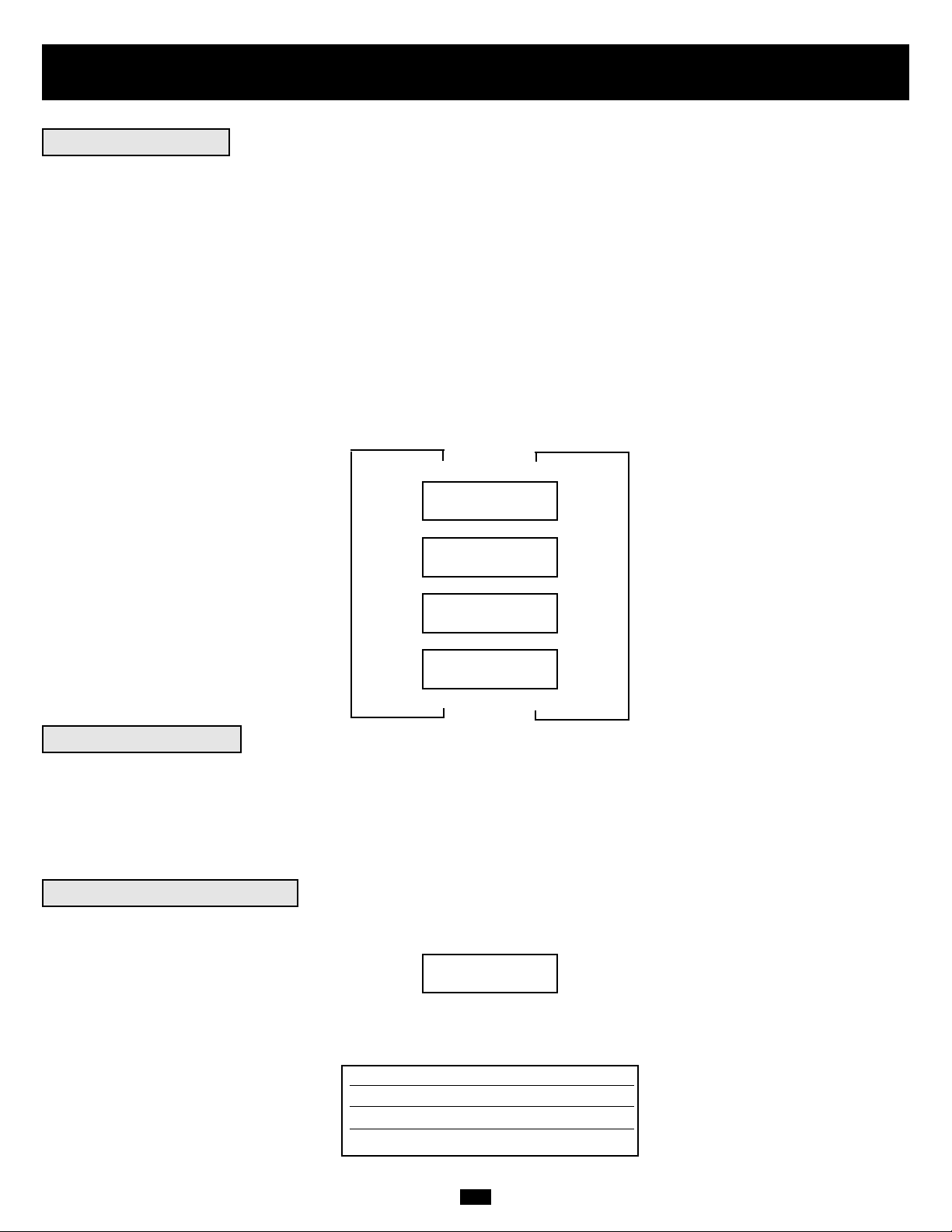
48
Operación
(continuación)
Durante operación normal, la primera línea de su pantalla LCD muestra el modo de operación de su UPS: Online, Economy, On Battery, o Bypass.
Modo Online: El UPS proporciona energía de corriente alterna mientras hay disponible energía de la red y cambia a modo On Battery en
forma instantánea (tiempo de transferencia cero) si se interrumpe la energía de CA.
Modo Economy: El UPS proporciona energía de corriente alterna de alta eficiencia mientras hay disponible energía de la red y cambia a
modo On Battery rápidamente si se interrumpe la energía de CA.
Modo On Battery: El UPS proporciona energía de corriente alterna de respaldo de batería por tanto tiempo como dure la energía de la
batería. Regresa a modo Online o Economy si hay energía de la red disponible y se apaga si se agota la energía de batería.
Modo Bypass: El UPS proporciona energía de corriente alterna mientras haya energía de la red disponible. El UPS se apaga si se interrumpe la corriente alterna.
La segunda línea de la pantalla LCD muestra condiciones básicas de energía. Presione los botones de desplazamiento para moverse a través de
estas condiciones en la secuencia siguiente:
XXXX MODE
LOAD = XXX% X.XXKW
XXXX MODE
IN = XXXV XX.X Hz
XXXX MODE
OUT = XXXV XX.X Hz
XXXX MODE
BATTERY = XXXVDC
M
M
M
Cuando está en modo On Battery, el módulo de potencia del UPS emitirá un pitido para informarle que está usando energía de baterías para
dar soporte al equipo conectado. Si sus baterías conectadas están a más de la mitad de su capacidad, emitirá un pitido cada dos segundos.
Si sus baterías conectadas están a menos de la mitad de su capacidad, emitirá un pitido dos veces por segundo. Si sus baterías conectadas
están casi agotadas, el módulo de potencia del UPS emitirá pitidos en forma continua.
Para silenciar la alarma On Battery, presione el botón “ON/MUTE”
Cuando el UPS detecta una sobrecarga de salida, la pantalla LCD cambiará a la siguiente visualización:
El UPS luego comenzará una cuenta regresiva. Si el UPS todavía está sobrecargado al final del conteo, pasará automáticamente a modo Bypass
para proteger su inversor. La duración del conteo regresivo varía con la gravedad de la sobrecarga, de la manera siguiente:
OVERLOAD!
LOAD = XXX% X.XXKW
Condición de sobrecarga Duración del conteo
102% - 125% 1 minuto
125% - 150% 30 segundos
>150% Inmediato
M
M
L
L
L
Operación normal
Alarma On Battery
Mensajes de sobrecarga
MODO XXXX
CARGA = XXX% X.XXKW
MODO XXXX
ENTRADA = XXXV XX.X Hz
MODO XXXX
SALIDA = XXXV XX.X Hz
MODO XXXX
BATERÍA = XXXVDC
¡SOBRECARGA!
CARGA = XXX% X.XXKW
Page 49

49
Operación
(continuación)
Durante modo Bypass, el UPS vigila su voltaje de entrada y pasa esa energía de entrada al equipo conectado. El UPS no proporcionará
respaldo de batería en modo Bypass.
Si el voltaje de salida se desvía de un rango aceptable (entre 15% mayor y 20% menor que el nominal), el UPS indica la condición en su
LCD y deja de suministrar energía de salida a su carga. Si los niveles de energía regresan a un nivel aceptable, el UPS reanuda el suministro
de energía a la carga, y su pantalla LCD informa que el voltaje de salida era demasiado alto o demasiado bajo, pero que ha regresado a su
valor nominal.
>15% mayor que
el nominal
>20% menor que
el nominal
Era muy alto,
ahora nominal
Era muy bajo,
ahora nominal
CONDICIONES DE
VOLTAJE DE BYPASS
MENSAJES DE
PANTALLA LCD
Su UPS se apagará y la pantalla LCD mostrará un mensaje si detecta una de las siguientes condiciones. Nota: Durante todas estas condiciones,
los LEDs “Input,” “Output” y “Bypass” estarán encendidos.
Sobrecarga prolongada
Cortocircuito en salida
Comando de apagado
remoto (Vía DB9)
Comando de apagado
remoto (Vía EPO)
CONDICIONES DE
APAGADO
MENSAJES DE
PANTALLA LCD
Fallas internas
NO OUTPUT BYPASS
AC TOO HI
NO OUTPUT BYPASS
AC TOO LO
BYPASS MODE BYPASS
AC WAS HI
BYPASS MODE BYPASS
AC WAS LO
SHUT DOWN
OVERLOAD XXX%
SHUT DOWN
O/P SHORT CIRCUIT
SHUT DOWN
REMOTE COMMAND
SHUT DOWN
EMERGENCY STOP!
SHUT DOWN
+ DC BUS HIGH
SHUT DOWN
+ DC BUS LOW
SHUT DOWN
- DC BUS HIGH
SHUT DOWN
- DC BUS LOW
SHUT DOWN
OVERTEMPERATURE
Mensajes Bypass
Mensajes de apagado
SIN SALIDA DE BYPASSVCA
MUY ALTO
SIN SALIDA DE BYPASSVCA
MUY BAJO
MODO BYPASSVCA
ERA ALTO
MODO BYPASSVCA
ERA BAJO
APAGADO
SOBRECARGA XXX%
APAGADO CORTO
CIRCUITO EN SALIDA
APAGADO
COMANDO REMOTO
APAGADO ¡PARADA DE
EMERGENCIA!
APAGADO BARRA
+ VCC ALTO
APAGADO BARRA
+ VCC BAJO
APAGADO BARRA
+ VCC ALTO
APAGADO BARRA
+ VCC BAJO
APAGADO
SOBRETEMPERATURA
Page 50

50
Almacenamiento,
Servicio y Garantía
Antes de almacenar su no-break, apáguelo completamente. Si va a almacenar su no-break por un tiempo prolongado, recargue sus baterías
durante 4 a 6 horas cada tres meses. Nota: Después de conectar el no-break a la energía de la red, comenzará automáticamente a cargar sus
baterías. Si deja descargadas las baterías del no-break durante un tiempo prolongado, sufrirán una pérdida de capacidad permanente.
Su no-break SmartOnline está cubierto con la garantía limitada de 2 años descrita más adelante. Tripp Lite tiene disponibles varios programas de Garantía extendida y Servicio en el sitio. Para mayor información sobre el servicio, llame al Soporte al cliente de Tripp Lite al
(773) 869-1234.
Antes de enviar su no-break para que le presten servicio, siga los siguientes pasos:
1. Verifique las instrucciones de instalación y operación en este manual para asegurarse que el problema de servicio no sea causado por una
mala interpretación de las instrucciones. Además, verifique que los interruptores automáticos del no-break no hayan disparado. Esta es la causa
más común de pedidos de servicio que pueden ser solucionados fácilmente siguiendo las instrucciones de restablecimiento en este manual.
2. Si el problema continúa, no contacte con el distribuidor ni devuelva el no-break. En su lugar, llame a Tripp Lite al (773) 869-1233. Un técnico de servicio le pedirá el modelo, número de serie y fecha de compra del no-break y tratará de resolver el problema a través del teléfono.
3. Si el problema requiere servicio, el técnico le emitirá un número de Autorización de devolución de mercadería (RMA), necesario para
que le presten servicio. También le explicará los procedimientos adecuados de embalaje y despacho. Cualquier daño (directo, indirecto,
especial, accidental o resultante) al no-break producido durante el despacho a Tripp Lite o a un centro autorizado de servicio Tripp Lite no
está cubierto por la garantía. Los no-break enviados a Tripp Lite o a algún centro de servicio autorizado de Tripp Lite deben tener los cargos de transporte prepagados. Marque el número RMA en la parte externa del paquete embalado. Si el no-break está dentro del período de
garantía de 2 años, adjunte una copia de su recibo de compra. Devuelva el no-break para servicio a la dirección dada por el técnico de Tripp
Lite utilizando un transportista asegurado.
TRIPP LITE garantiza que sus productos que incluyen baterías están libres de defectos en materiales y mano de obra por un período de dos años a partir de la fecha de compra.
Después de 90 días de la fecha de compra, la obligación de TRIPP LITE de acuerdo con esta garantía está limitada a reemplazar componentes en los productos defectuosos. Para
obtener servicio de acuerdo con esta garantía, debe llamar a TRIPP LITE o a un centro de servicio autorizado de TRIPP LITE. Los productos deben ser devueltos a TRIPP LITE o
a un centro de servicio autorizado de TRIPP LITE con los cargos de transporte pagados por adelantado, acompañados de una breve descripción del problema encontrado y un
comprobante de la fecha y el lugar de compra. Esta garantía no se aplica al equipo que ha sido dañado por accidente, negligencia o uso inadecuado, o que ha sido alterado o modificado en alguna forma. Esta garantía solamente se aplica al comprador original que debe haber registrado correctamente el producto dentro de los 10 días de la compra.
Las garantías de todos los supresores de sobretensiones de TRIPP LITE son nulas si han estado conectados a la salida de cualquier sistema UPS.Las garantías de todos los sistemas UPS de TRIPP LITE son nulas si un supresor de sobretensiones ha estado conectado a sus tomas de salida.
SALVO POR LO ESTABLECIDO EN ESTE DOCUMENTO, TRIPP LITE NO EXPRESA NINGUNA GARANTÍA, EXPRESA O IMPLÍCITA, INCLUYENDO GARANTÍAS DE COMERCIABILIDAD O IDONEIDAD PARA UN PROPÓSITO PARTICULAR. Algunos estados no permiten limitaciones o exclusiones de las garantías implícitas; por lo tanto, las limitaciones
o exclusiones mencionadas anteriormente pueden no aplicarse al comprador.
SALVO POR LO ESTABLECIDO ANTERIORMENTE, EN NINGÚN CASO TRIPP LITE SERÁ RESPONSABLE POR DAÑOS DIRECTOS, INDIRECTOS, ESPECIALES, INCIDENTALES O EMERGENTES, RESULTANTES DEL USO DE ESTE PRODUCTO, INCLUSO EN EL CASO DE HABERSE INFORMADO DE LA POSIBILIDAD DE DICHOS DAÑOS.
Específicamente, TRIPP LITE no es responsable por ningún costo, como pérdida de ingresos o beneficios, pérdida de equipos, pérdida de uso de equipos, pérdida de software,
pérdida de datos, costo por reemplazos, reclamaciones de terceras partes, o lo que corresponda.
TRIPP LITE tiene una política de mejoramiento continuo. Las especificaciones están sujetas a cambio sin previo aviso.
Servicio
Garantía limitada de 2 años
Almacenamiento
Page 51

51
Especificaciones (Modelos con transformador)
Los modelos indicados a continuación incluyen un módulo de potencia, uno o dos módulos de baterías y un módulo de transformador.
Todos los modelos indicados abajo incluyen los tres tipos de módulos con la excepción de la opción de 5 kVA donde el módulo de
transformador (modelo: SU5000XFMRT2U) se vende por separado del módulo de potencia y del módulo de batería (modelo:
SU5000RT3UHV). De acuerdo con el modelo ordenado, puede incluir un módulo de batería extensible o no extensible. Sin embargo, todos
los módulos de potencia son totalmente compatibles con los módulos de batería de Tripp Lite (Tripp Lite modelo # BP240V10RT-3U, vendido por separado) si se requiere tiempo de respaldo extensible.
Información del modelo
Modelo #(s) SU5000RT3UHV y SU5000XFMRT2U* SU6000RT3U SU6000RT3UXR SU10KRT3U
Los paquetes incluyen:
Módulo de potencia (Modelo: SU5000RT3UPM; (Modelo: SU6000RT3UPM; (Modelo: SU6000RT3UPM; (Modelo: SU10KRT3UPM;
Serie: AGPS5124) Serie: AGSU60003U) Serie: AGSU60003U) Serie: AGSU100003U)
Módulo de batería #1 (Modelo: BP240V5RT2U; (Modelo: BP240V7RT3U; (Modelo: BP240V10RT3U; (Modelo: BP240V10RT3U;
Serie: AGBP5161) Serie: AGBP240V7RT3U) Serie: AGBP240V7RT3U) Serie: AGBP240V7RT3U)
No extensible No extensible EXTENSIBLE EXTENSIBLE
Módulo de batería #2 N/D N/D (Modelo: BP240V7RT3U; N/D
Serie: AGBP240V7RT3U)
No extensible
Módulo del transformador * Módulo del transformador (Modelo: SU6000XFMRRT3U; (Modelo: SU6000XFMRRT3U; (Modelo: SU10KXFMRRT3U;
¡Vendido por separado! Serie: AGSM6000SDRT3U) Serie: AGSM6000SDRT3U) Serie: AGSM10KSDRT3U)
(Modelo: SU5000XFMRT2U;
Serie: AGAC5125)
Aprobado por: Todos los módulos de potencia (UL, cUL, NOM, CE, GOST, SASO, IRAM, FCC Clase A).Todos los módulos de baterías (UL, cUL, NOM). Todos los módulos de transformador (UL,
cUL, NOM, FCC Clase A)
Entrada
Tipo de conexión de entrada Cordón de 3 m (10 pies) con enchufe L6-30P Cableado Cableado Cableado
Rango de voltaje de entrada 156V~276V monofásico 156V~276V monofásico 156V~276V monofásico 156V~276V monofásico
Voltaje de entrada del módulo 200/208/220/230/240VCA 200/208/240VCA 200/208/240VCA 200/208/240VCA
Frecuencia de entrada 50/60 Hz ± 3 Hz 50/60 Hz ± 3 Hz 50/60 Hz ± 3 Hz 50/60 Hz ± 3 Hz
Corriente de entrada 20 A 22.6 A 22.6 A 40 A
Corriente de arranque <150 A <150 A <150 A <200 A
Factor de potencia (plena carga) >0.97 >0.97 >0.97 >0.97
Eficiencia (plena carga/en línea) >87% >87% >87% >88%
Interruptor automático del módulo de potencia N/D 40A (bipolar) 40A (bipolar) 63A (bipolar)
Interruptor automático del módulo del transformador N/D 40A (bipolar) 40A (bipolar) 63A (bipolar)
Salida
VA 5000 6000 6000 10000
Vatios (Factor de potencia: 0.7) 3500 4200 4200 7000
Tipo de conexión de salida 4 tomas en módulo de potencia Cableado Cableado Cableado
(2 L6-20R y 2 L6-30R) y
12 tomas en módulo de
transformador (5-15/20R)
Forma de onda (con línea) Onda sinusoidal Onda sinusoidal Onda sinusoidal Onda sinusoidal
Forma de onda (con batería) Onda sinusoidal Onda sinusoidal Onda sinusoidal Onda sinusoidal
Voltaje de salida (RMS) 120*/200/208/220/230/240VCA 100/120/200/208/240VCA 100/120/200/208/240VCA 100/120/200/208/240VCA
Frecuencia de salida 50/60 Hz (± 0.2 Hz con batería) 50/60 Hz (± 0.2 Hz con batería) 50/60 Hz (± 0.2 Hz con batería) 50/60 Hz (± 0.2 Hz con batería)
Regulación de voltaje ±3% ±3% ±3% ±3%
Distorsión máxima de armónicos
(Plena carga lineal) <3% <3% <3% 3%
(Plena carga no lineal) <6% <6% <6% 6%
Capacidad de sobrecarga 102% (continua) 102% (continua) 102% (continua) 102% (continua)
102%~125% (1 min.) 102%~125% (1 min.) 102%~125% (1 min.) 102%~125% (1 min.)
125%~150% (30 seg.) 125%~150% (30 seg.) 125%~150% (30 seg.) 125%~150% (30 seg.)
>150% (inmmediato) >150% (inmmediato) >150% (inmmediato) >150% (inmmediato)
Capacidad de cortocircuito 90A 90A** 90A** 160A**
Interruptor automático del módulo de potencia 20A (bipolar) 40A 63A 63A
Interruptor automático de módulo
de transformador* Cuatro de 20A (unipolar) 30A (tripolar) 63A (tripolar) 63A (tripolar)
Factor de cresta 3:1 3:1 3:1 3:1
* Módulo de transformador vendido por separado con opción de 5 kVA. **La capacidad de cortocircuito en 2 hilos, monofásico, 120 V para modelos SU6000RT3U y SU6000RT3UXR es mayor que 180 A, y
para el SU10KRT3U es mayor que 320 A..
Operación
Tiempo de transferencia en línea
(Línea a batería, batería a línea) 0 ms 0 ms 0 ms 0 ms
Ruido audible (Plena carga @ 1 m) <50 dBA <50 dBA <55 dBA <55 dBA
Indicadores
Incluye una pantalla LCD y LEDs (I/P (entrada), BATTERY, AC/DC, BYPASS DC/AC, O/P (salida)).
Comunicaciones
Incluye un conector RS-232 hembra, un conector DB9 hembra de contacto seco y una ranura auxiliar.
Especificaciones físicas
Dimensiones de la unidad (Alt. x ancho x prof., pulg.)
Módulo de potencia 5.25 (3U) x 17.5 x 26 pulg. 5.25 (3U) x 17.5 x 22.5 pulg. 5.25 (3U) x 17.5 x 22.5 pulg. 5.25 (3U) x 17.5 x 22.5 pulg.
[13.4 x 44.5 x 66 cm.] [13.4 x 44.5 x 57.2 cm.] [13.4 x 44.5 x 57.2 cm.] [13.4 x 44.5 x 57.2 cm.]
Módulo de transformador* 3.5 (2U) x 17.5 x 20.75 pulg. 5.25 (3U) x 17.5 x 26 pulg. 5.25 (3U) x 17.5 x 26 pulg. 5.25 (3U) x 17.5 x 26 pulg.
[8.9 x 44.5 x 52.7 cm.] [13.4 x 44.5 x 66.1 cm.] [13.4 x 44.5 x 66.1 cm.] [13.4 x 44.5 x 66.1 cm.]
Módulo de batería #1 3.5 (2U) x 17.5 x 20.75 pulg. 5.25 (3U) x 17.5 x 22.5 pulg. 5.25 (3U) x 17.5 x 22.5 pulg. 5.25 (3U) x 17.5 x 22.5 pulg.
[8.9 x 44.5 x 52.7 cm.] [13.4 x 44.5 x 57.2 cm.] [13.4 x 44.5 x 57.2 cm.] [13.4 x 44.5 x 57.2 cm.]
Módulo de batería #2 (si es aplicable) N/D N/D 5.25 (3U) x 17.5 x 22.5 pulg. N/D
[13.4 x 44.5 x 57.2 cm.]
Peso de embarque
Módulo de potencia 58 lb. [27 kg.] 58 lb. [27 kg.] 58 lb. [27 kg.] 68 lb. [31 kg.]
Módulo de transformador* 60 lb. [28 kg.] 124 lb. [57 kg.] 124 lb. [57 kg.] 124 lb. [57 kg.]
Módulo de batería #1 95 lb. [43 kg.] 160 lb. [73 kg.] 160 lb. [73 kg.] 160 lb. [73 Kg.]
Módulo de batería #2 (si es aplicable) N/D N/D 160 lb. [73 kg.] N/D
* Módulo de transformador vendido por separado con opción de 5 kVA.
Page 52

52
Especificaciones (Modelos sin transformador)
Los modelos indicados a continuación incluyen un módulo de potencia y un módulo de batería. De acuerdo con el modelo ordenado, puede
incluir un módulo de batería extensible o no extensible. Sin embargo, todos los módulos de potencia son totalmente compatibles con los módulos de batería de Tripp Lite (Tripp Lite modelo # BP240V10RT-3U, vendido por separado) si se requiere tiempo de respaldo extensible.
Información del modelo
Modelo #(s) SU5000RT3UHV SU6000RT3UHV SU10KRT3UHV
Los paquetes incluyen:
Módulo de potencia (Modelo: SU5000RT3UPM; (Modelo: SU6000RT3UPM; (Modelo: SU10KRT3UPM;
Serie: AGPS5124) Serie: AGSU60003U) Serie: AGSU100003U)
Módulo de batería #1 (Modelo: BP240V5RT2U; serie: AGBP5161) (Modelo: BP240V7RT3U; (Modelo: BP240V10RT3U;
No extensible Serie: AGBP240V7RT3U) Serie: AGBP240V7RT3U)
No extensible EXTENSIBLE
Aprobado por: Todos los módulos de potencia (UL, cUL, NOM, CE, GOST, SASO, IRAM, FCC Clase A). Todos los módulos de baterías (UL, cUL, NOM).
Entrada
Tipo de conexión de entrada Cordón de 3 m (10 pies) con enchufe L6-30P Cableado Cableado
Rango de voltaje de entrada 156V~276V monofásico 156V~276V monofásico 156V~276V monofásico
Voltaje de entrada del módulo 200/208/220/230/240VCA 200/208/240VCA 200/208/240VCA
Frecuencia de entrada 50/60 Hz ± 3 Hz 50/60 Hz ± 3 Hz 50/60 Hz ± 3 Hz
Corriente de entrada 20 A 22.6 A 40 A
Corriente de arranque <150 A <150 A <200 A
Factor de potencia (plena carga) >0.97 >0.97 >0.97
Eficiencia (Plena carga/En línea) >87% >87% >88%
Interruptor automático del módulo de potencia N/D 40A (bipolar) 63A (bipolar)
Salida
VA 5000 6000 10000
Vatios (Factor de potencia: 0.7) 3500 4200 7000
Tipo de conexión de salida 4 tomas Cableado Cableado
(2 L6-20R y 2 L6-30R)
Forma de onda (con línea) Onda sinusoidal Onda sinusoidal Onda sinusoidal
Forma de onda (con batería) Onda sinusoidal Onda sinusoidal Onda sinusoidal
Voltaje de salida (RMS) 200/208/220/230/240VCA 200/208/240VCA 200/208/240VCA
Frecuencia de salida 50/60 Hz (± 0.2 Hz con batería) 50/60 Hz (± 0.2 Hz con batería) 50/60 Hz (± 0.2 Hz con batería)
Regulación de voltaje ±3% ±3% ±3%
Distorsión máxima de armónicos
(Plena carga lineal) <3% <3% <3%
(Plena carga no lineal) <6% <6% <6%
Capacidad de sobrecarga 102% (continua) 102% (continua) 102% (continua)
102%~125% (1 min.) 102%~125% (1 min.) 102%~125% (1 min.)
125%~150% (30 seg.) 125%~150% (30 seg.) 125%~150% (30 seg.)
>150% (inmediato) >150% (inmediato) >150% (inmediato)
Capacidad de cortocircuito 90A 90A 160A
Interruptor automático del módulo de potencia 20A (bipolar) 40A 63A
Factor de cresta 3:1 3:1 3:1
Operación
Tiempo de transferencia en línea
(Línea a batería, batería a línea) 0 ms 0 ms 0 ms
Ruido audible (Plena carga @ 1 m) <50 dBA <50 dBA <55 dBA
Indicadores
Incluye una pantalla LCD y LEDs (I/P (entrada), BATTERY, AC/DC, BYPASS DC/AC, O/P (salida)).
Comunicaciones
Incluye un conector RS-232 hembra, un conector DB9 hembra de contacto seco y una ranura auxiliar.
Especificaciones físicas
Dimensiones de la unidad (Alt. x ancho x prof.)
Módulo de potencia 5.25 (3U) x 17.5 x 26 pulg. 5.25 (3U) x 17.5 x 22.5 pulg. 5.25 (3U) x 17.5 x 22.5 pulg.
[13.4 x 44.5 x 66 cm.] [13.4 x 44.5 x 57.2 cm.] [13.4 x 44.5 x 57.2 cm.]
Módulo de batería 3.5 (2U) x 17.5 x 20.75 pulg. 5.25 (3U) x 17.5 x 22.5 pulg. 5.25 (3U) x 17.5 x 22.5 pulg.
[8.9 x 44.5 x 52.7 cm.] [13.4 x 44.5 x 57.2 cm.] [13.4 x 44.5 x 57.2 cm.]
Peso de embarque
Módulo de potencia 58 lb. [27 kg.] 58 lb. [27 kg.] 68 lb. [31 kg.]
Módulo de batería 95 lb. [43 kg.] 160 lb. [73 kg.] 160 lb. [73 Kg.]
AVISO DE FCC SOBRE INTERFERENCIA DE RADIO / TV:
Nota: Este equipo ha sido probado y cumple con los límites para un dispositivo digital Clase A, de acuerdo con la Parte 15 de las Reglas FCC. Estos límites están diseñados para proporcionar
una protección razonable contra interferencia perjudicial durante la operación en un ambiente comercial. Este equipo genera, usa y puede radiar, energía de radio frecuencia, y si no se instala
y usa de acuerdo con el manual de instrucciones, puede causar interferencia a las comunicaciones por radio. Es probable que la operación de este equipo produzca interferencia perjudicial en
cuyo caso el usuario deberá corregir la interferencia por su cuenta. El usuario debe utilizar cables y conectores blindados con este producto. Cualquier cambio o modificación a este producto
no expresamente autorizado por la parte responsable del cumplimiento de las normas, podría anular la autoridad del usuario para operar el equipo.
Cumplimiento de las normas de los números de identificación
Para fines de identificación y certificación del cumplimiento de las normas, su producto Tripp Lite tiene asignado un número de serie único. Puede encontrar el número de serie en la etiqueta
de la placa de identificación del producto, junto con los símbolos de aprobación e información requeridos. Al solicitar información sobre el cumplimiento de las normas para este producto,
siempre mencione el número de serie. El número de serie no debe ser confundido con el nombre de identificación ni con el número de modelo del producto.
Page 53

Manuel de l'utilisateur
1111 W. 35th Street • Chicago, IL 60609 USA
Service Clientèle : (773) 869-1234 • Services Application : (773) 869-1236 • www.tripplite.com
Copyright ©2004 Tripp Lite. Tous droits réservés.
SmartOnline™Monophasé 5kVA, 6kVA & 10kVA
Intelligent True On-Line UPS Systems
(Montage dans baie/Tour)
Pour tous les Systèmes d'alimentation continue sans coupure (module d'alimentation, module de transformateur et
module à piles) vendus séparément ou combinés. Les modules de Système d'alimentation continue sans coupure de
sélection peuvent inclure des instructions séparées ou des fiches d'avertissement qui doivent être utilisées en con-
jonction avec ce manuel.
Consignes de Sécurité Importantes
Montage
Connexion
Caractéristiques
Fonctionnement
Entreposage, Entretien, Garantie et Assurance
Spécifications
English/Español/Русский
54
55
57
62
73
76
77
1/27/79
Connexion en Option
69
Alimentation en Marche/Arrêtée
70
Opération Bypass Manuelle
72
Page 54

54
Consignes de Sécurité Importantes
CONSERVEZ CES INSTRUCTIONS. Ce manuel contient des instructions importantes et avertissements qui doivent être suivis durant l'installation
et la maintenance de tous les Systèmes d'alimentation continue sans coupure Montage dans baie/Tour Tripp Lite SmartOnline et leurs batteries.
Avertissements pour Emplacement de Système d'alimentation continue sans coupure
• Installer votre Système d'alimentation continue sans coupure à l'intérieur, à l'abri d'humidité ou de chaleur excessive, lumière directe du soleil, poussière et contaminateurs conducteurs.
• Installer votre Système d'alimentation continue sans coupure dans un zone structurellement saine. Votre Système d'alimentation
continue sans coupure est très lourd ; prendre toutes précautions pour déplacer et lever l'unité.
• Utiliser votre Système d'alimentation continue sans coupure seulement à des températures à l'intérieur entre 32° F et 104° F (entre 0° C et 40° C).
Pour obtenir les meilleures performances, garder les températures à l'intérieur entre 62° F et 84° F (entre 17° C et 29° C).
• Laisser un espace suffisant autour de tous les côtés de votre Système d'alimentation continue sans coupure pour une ventilation appropriée.
• Ne pas installer le Système d'alimentation continue sans coupure près de moyens de stockage magnétiques, pour éviter tout risque de corruption de données.
Avertissements pour Connexion de Système d'alimentation continue sans coupure
• L'alimentation électrique pour cette unité doit être monophasée conformément à la plaque d'identification de l'équipement. Elle doit aussi être mise à
terre correctement.
Avertissements pour Connexion de l'Equipement
• Ne pas utiliser les Systèmes d'alimentation continue sans coupure Tripp Lite pour des applications de maintien en vie pour lesquelles un dysfonctionnement ou une défaillance d'un Système d'alimentation continue sans coupure pourraient provoquer une panne ou affecter sensiblement les performances d'un appareil de maintien en vie.
• Branchez la borne de mise à la terre de votre module d'alimentation UPS et/ou module de transformateur à une électrode de mise à la terre.
• Le Système d'alimentation continue sans coupure est connecté à une source d'énergie CC (batterie). Les bornes de sortie peuvent être activées quand
le Système d'alimentation continue sans coupure n'est pas connecté à une alimentation CA.
Avertissements pour Maintenance
• Votre module d'alimentation UPS, module de transformateur et module(s) de piles ne requièrent aucun entretien routinier. Ne les ouvrez en aucun
cas. Ils ne contiennent aucune pièce nécessitant un entretien de la part de l'utilisateur.
Avertissements pour Batterie
• Ne pas utiliser votre Système d'alimentation continue sans coupure sans le connecter à un module de batterie externe.
• Ne branchez, au connecteur de piles externe de votre module d'alimentation UPS, que les modules à piles Tripp Lite (de type et de tension adéquats).
• Les batteries dans votre module de batterie sont recyclables. Se référer aux codes locaux pour les conditions de mise au rebut, ou aux Etats-Unis
appeler le 1-800-SAV-LEAD (1-800-728-5323) pour toutes informations sur le recyclage. ATTENTION : Ne pas jeter les batteries dans un feu, la
batterie risquerait d'exploser.
• Du fait que les batteries présentent un risque de chocs électriques et de brûlures à cause d'un fort courant de court-circuit, les batteries doivent être
changées seulement par le personnel d'entretien qualifié prenant toutes les précautions nécessaires. Consulter votre manuel de module de batterie
avant de procéder. Enlever les montres, bagues, et autres objets métalliques. Utiliser des outils avec des manches isolés. Porter des gants en
caoutchouc et des bottes. Ne pas poser des outils ou des pièces métalliques sur les batteries. Ne pas mettre en court-circuit ou relier les bornes de
batterie à tout objet. Déconnecter la source de charge avant de connecter ou déconnecter les bornes de batterie. Déterminer si les batteries sont mises
à la terre par inadvertance. Si elles sont mises à la terre par inadvertance, enlever la source de mise à la terre. Le contact avec toute partie d'une batterie
mise à la terre peut provoquer un choc électrique. Les risques d'un tel choc seront réduits si ces mises à la terre sont enlevées durant l'installation et
la maintenance.
• Ne pas ouvrir ou abîmer les batteries. L'électrolyte libérée est nocive pour la peau et les yeux, et peut être toxique.
• Les fusibles doivent être remplacés seulement par le personnel en usine agréé. Les fusibles brûlés doivent être remplacés seulement par le même
nombre et type de fusibles.
• L'entretien et les réparations doivent être effectués seulement par le personnel qualifié. Avant d'effectuer toute opération d'entretien sur un module
câblé, celui-ci doit avoir été éteint ou dérivé manuellement vers le transformateur. Avant d'effectuer toute opération d'entretien sur un module d'alimentation se connectant directement à une prise murale, celui-ci doit avoir été éteint et débranché. Noter que des tensions potentiellement mortelles
existent dans cette unité quand l'alimentation de la batterie est connectée.
• Ne branchez ou ne débranchez pas le(s) module(s) de piles lorsque le UPS fonctionne à partir de l'alimentation à piles ou lorsque le module de transformateur n'est pas en mode de dérivation (si votre système UPS comprend un module de transformateur avec un interrupteur de dérivation).
• Durant le remplacement du pack de batteries “à chaud”, votre Système d'alimentation continue sans coupure ne pourra pas assurer une alimentation
de secours de la batterie en cas de coupure de courant.
Page 55

55
Montage (Baie)
1
Montage à 4 supports
1
2
3
A
B
C
F
E
G
4
H
Connecter les deux segments de chaque étagère en utilisant les vis et écrous à oreilles .
Laisser les vis légèrement desserrées de manière à ce que les étagères puissent être ajustées
à la procédure suivante.
Ajuster chaque étagère pour fixer votre baie, puis les monter dans l'espace disponible le plus bas
de votre baie avec les vis, écrous et rondelles fournis . Noter que les arceaux de support
doivent être dirigés vers l'intérieur. Serrer les vis qui relient les segments d'étagère .
Fixer les oreilles de montage aux trous de montage avant de votre équipement en utilisant les vis fournies . Les oreilles doivent être dirigées vers l'avant.
Avec l'aide d'un assistant, lever votre équipement et le faire coulisser sur les étagères de
montage. Fixer votre équipement sur la baie en faisant passer les vis, écrous et rondelles
(fournis par l'utilisateur) par ses oreilles de montage et dans les rails de la baie.
Pour monter votre équipement dans une baie à 2 supports, vous devez acquérir un Kit
d'Installation de Montage de Baie à 2 Supports Tripp Lite (modèle : 2POSTRMKIT, vendu
séparément) pour chaque module installé. Voir le manuel de l'utilisateur de Kit d'Installation pour
toutes instructions de montage.
H
G
FE
D
C
BA
4
Monter votre équipement dans une baie à 4 supports ou 2 supports ou une enceinte de baie. L'utilisateur doit déterminer l'aptitude du matériel et les procédures avant le montage. Si le matériel et les procédures ne sont pas appropriés pour votre application, contacter le fabricant de votre baie ou de votre
enceinte de baie. Les procédures décrites dans ce manuel sont pour les types de baie et d'enceinte de baie ordinaires et peuvent ne pas être appropriées pour
toutes les applications.
AVERTISSEMENT!
Tous les modules de système UPS sont extrêmement lourds ! Faites attention lorsque vous les soulevez ou les installez!
L'utilisateur doit stabiliser adéquatement le module lorsqu'il le soulève ou l'installe.
2
3
Montage à 2 supports (Telecom)
B
D
Page 56

56
Montage (Tour)
AVERTISSEMENT!
Tous les modules de système UPS sont extrêmement lourds ! Faites
attention lorsque vous les soulevez ou les installez! L'utilisateur doit
stabiliser adéquatement le module lorsqu'il le soulève ou l'installe.
Faire tourner le Panneau de Commande du module d'alimentation pour le voir plus facilement
quand le Système d'alimentation continue sans coupure est monté en tour. Insérer un petit
tournevis, ou un autre outil, dans les slots de chaque côté du Panneau de Commande. Dégager le
panneau ; le faire tourner ; et remettre en place le panneau.
Tous les modules doivent être installés en position debout lorsque utilisés avec une base ajustable optionnelle, vendue séparément par Tripp Lite (modèle
no. 2-9USTAND). Lorsque vous installez un module sur une base ajustable, assurez-vous que le panneau de contrôle du module d'alimentation se trouve
sur le coté supérieur. Si vous installez aussi un module de transformateur, placez-le entre le module d'alimentation et son module à piles.
Page 57

57
Caractéristiques
Trois modules de Système d'alimentation continue sans coupure séparés sont disponibles chez Tripp Lite (module d'alimentation, module de transformateur et module à piles) utilisés dans une variété de combinaisons. Familiarisez-vous avec l'emplacement et la fonction des caractéristiques de chaque module avant d'installer et d'utiliser votre Système d'alimentation continue sans coupure. Le module d'alimentation est le seul module qui inclut les caractéristiques du panneau avant.
Commandes de Panneau Avant de Module d'Alimentation
1. AFFICHAGE LCD : Cet affichage de matrice à points (16x2 caractères) à éclairage arrière indique une large échelle de conditions de fonctionnement
du Système d'alimentation continue sans coupure et de données de diagnostic. Il affiche aussi les réglages du Système d'alimentation continue sans
coupure et les options quand le Système d'alimentation continue sans coupure est en mode configuration.
2. BOUTON ON/SILENCE: Appuyer sur ce bouton et le maintenir enfoncé jusqu'à ce que vous entendiez un bip pour mettre en fonction l'inverseur du
Système d'alimentation continue sans coupure. Si l'alarme sonore de la batterie du Système d'alimentation continue sans coupure se déclenche, appuyez
sur ce bouton pour l'arrêter.
3. BOUTON DEFILEMENT BAS/QUITTER CONFIGURATION: Ce bouton vous permet de visualiser rapidement différentes options et lectures
d'alimentation sur l'affichage LCD. Quand il est pressé momentanément, l'écran LCD affiche une lecture d'alimentation différente (voir
“Fonctionnement”). Quand il est pressé en même temps que le bouton DEFILEMENT HAUT, le Système d'alimentation continue sans coupure passe
en mode configuration, où ce bouton est utilisé pour faire défiler les options de configuration et pour quitter le mode configuration.
4. BOUTON DEFILEMENT HAUT/SELECTION : Ce bouton vous permet de visualiser rapidement différentes options et lectures d'alimentation. sur
l'affichage LCD. Quand il est pressé momentanément, l'écran LCD affiche une lecture d'alimentation différente (voir “Fonctionnement”). Quand il est
pressé en même temps que le bouton DEFILEMENT BAS, le Système d'alimentation continue sans coupure passe en mode configuration, où ce bouton est utilisé pour sélectionner les options de configuration.
5. BOUTON OFF : Appuyer sur ce bouton jusqu'à ce que vous entendiez un bip pour mettre hors fonction l'inverseur du Système d'alimentation continue sans coupure.
6. LED O/P (SORTIE) : Ce voyant vert s'allume pour indiquer que votre Système d'alimentation continue sans coupure délivre une alimentation CA à
l'équipement connecté.
7. LED CC/CA (INVERSEUR) : Ce voyant vert s'allume pour indiquer que l'inverseur CC/CAdu Système d'alimentation continue sans coupure est activé.
8. LED BYPASS : Ce voyant vert s'allume quand le Système d'alimentation continue sans coupure délivre une alimentation secteur filtrée sans mettre en
fonction son convertisseur ou inverseur. Si cette LED est allumée, l'équipement connecté ne recevra pas l'alimentation de la batterie en cas de coupure
de courant.
9. LED CA/CC (Convertisseur) : Ce voyant vert s'allume pour indiquer que le convertisseur CA/CC du Système d'alimentation continue sans coupure
est en train de charger le(s) pack(s) de batteries connecté(s).
10. LED BATTERIE : Ce voyant rouge s'allume quand le Système d'alimentation continue sans coupure est en train de décharger la batterie pour délivrer
une alimentation CA à l'équipement connecté. Une alarme sonore se déclenchera, qui peut être arrêtée en appuyant sur le bouton ON/SILENCE. Cette
LED restera allumée après l'arrêt de l'alarme.
11. LED I/P (ENTREE) : Ce voyant vert s'allume pour indiquer qu'une alimentation d'entrée CA est présente.
12. SLOTS ACCES : Pour tourner les commandes, insérer un tournevis à tête plate dans ces slots et dégager le panneau avec précautions. En veillant à
ne pas tordre ou tirer d'un coup sec de manière excessive les câbles connectant les commandes au reste du Système d'alimentation continue sans
coupure, tourner les commandes vers l'orientation voulue et les réinsérer.
1
2 345
6879
10
11
12
12
Page 58

58
Caractéristiques (panneau arrière)
voir la page 61 pour descriptions de caractéristiques
Module d'alimentation 5kVA
Module de transformateur 5kVA
Module à piles* 5kVA
* Le module d'alimentation 5kVA est livré avec un module à piles
non extensible, cependant, le module d'alimentation est totalement
compatible avec les modules à piles Tripp Lite qui eux sont extensibles (modèle Tripp Lite no. BP240V10RT-3U, vendu séparément) si vous désirez prolonger votre autonomie.
11
6
7
89
10
3
12
12
13
13
14
25
25
24 26 24
25
25
28
Page 59

59
Caractéristiques (Panneau Arrière)
voir la page 61 pour descriptions de caractéristiques
Module Alimentation 6kVA
Module Transformateur 6kVA
Module Batterie pour Modèle 6kVA*
54
6
7
89
10
16
17
15
12
20
21
3
1 2
11
13
18
19
* Module à piles extensible (modèle Tripp Lite no.
BP240V10RT-3U) montré. Selon le modèle commandé, le
module d'alimentation 6kVA peut avoir été livré avec un
module à piles extensible (comme celui montré ci-dessus) ou
avec un module non extensible. Tous les modules d'alimentation 6kVA, cependant, sont totalement compatibles avec les
modules à piles BP240V10RT-3U (vendus séparément) si
vous désirez prolonger votre autonomie.
Page 60

60
Caractéristiques (Panneau Arrière)
voir la page 61 pour descriptions de caractéristiques
Module Alimentation 10kVA
45
6
7
8
9
10
3
Module Batterie pour Modèle 10kVA*
20
21
Module Transformateur 10kVA
16
14
11
12
17
12
15
18 19
* Module à piles extensible (modèle Tripp Lite no.
BP240V10RT-3U) montré. Selon le modèle commandé, le
module d'alimentation 10kVA peut avoir été livré avec un
module à piles extensible (comme celui montré ci-dessus)
ou avec un module non extensible. Tous les modules d'alimentation 10kVA, cependant, sont totalement compatibles
avec les modules à piles BP240V10RT-3U (vendus séparément) si vous désirez prolonger votre autonomie.
Page 61

61
Caractéristiques (Panneau Arrière)
suite
Description des Caractéristiques de Module d'Alimentation
1. Bloc de Bornes de Sortie (Modèles 6kVA et 10kVA seulement) : Utiliser ces bornes pour connecter votre module d'alimentation à votre équipement
ou au module du transformateur. Dévisser et enlever le couvercle sur le bloc pour accès.
2. Blocs de Bornes d'Entrée (Modèles 6kVA et 10kVA seulement) : Utiliser ces bornes pour connecter votre module d'alimentation à l'alimentation de
service ou au module du transformateur. Dévisser et enlever le couvercle sur le bloc pour accès.
3. Connecteur de Batterie Externe : L'utiliser pour connecter un ou plusieurs modules de batterie Tripp Lite au module d'alimentation. Enlever le
couvercle pour accès. Le module d'alimentation ne démarrera pas sans une connexion à un module de batterie chargée. Se référer au manuel de
l'utilisateur de module de batterie pour les instructions de connexion et les consignes de sécurité.
4. Disjoncteur d'Entrée CA (Modèles 6kVA et 10kVA seulement) : Un disjoncteur de circuit bipolaire contrôle l'alimentation d'entrée au module
d'alimentation.
5. Disjoncteur de Sortie CA (Modèles 6kVA et 10kVA seulement) : Un disjoncteur de circuit bipolaire contrôle l'alimentation de sortie du module
d'alimentation.
6. Ventilateur d'Echappement : Il refroidit et ventile l'intérieur du module d'alimentation.
7. Slot Accessoires : Enlever le petit panneau couvercle pour installer les accessoires en option pour commander et contrôler à distance votre Système
d'alimentation continue sans coupure. Visiter Tripp Lite sur le Web (www.tripplite.com) pour informations sur SNMP, gestion de réseau et produits de
connectivité qui peuvent être installés dans ce slot.
8. Port EPO (Alimentation de Secours Off) : Le module d'alimentation comporte un port EPO qui peut être utilisé pour connecter le module
d'alimentation à un interrupteur de fermeture de contact pour couper l'alimentation de secours. Voir la section "Connexion en Option" pour tous détails.
9. Port de Communication RS-232 : Ce port série femelle DB9 peut être utilisé pour connecter votre Système d'alimentation continue sans coupure à une
station de travail ou un serveur. Il utilise le protocole RS-232 pour communiquer avec un ordinateur connecté. Il est utilisé avec le logiciel Tripp Lite
et le câble série inclus pour contrôler et gérer à distance le Système d'alimentation continue sans coupure sur un réseau et pour sauvegarder
automatiquement les fichiers ouverts et fermer l'équipement durant une coupure de courant. Voir "Connexion en Option" pour tous détails.
10. Port Interface de Contact Sec : Ce port DB9 femelle envoie des signaux de fermeture de contact pour indiquer la condition de défaillance de ligne
et de batterie faible. Voir “Connexion en Option” pour tous détails.
11. Disjoncteur de sortie 1 c.a. (modèles 5kVA seulement) : un disjoncteur de circuit bipolaire contrôle l'alimentation de sortie à partir des prises c.a. des
modules d'alimentation 5kVA étiquetées "Output 1" (sortie 1).
12. Prises de sortie 1 c.a. (modèles 5kVA seulement) : accepte les connexions directement enfichables des prises d'équipement NEMA L6-20P.
13. Prises de sortie 2 c.a. (modèles 5kVA seulement) : accepte les connexions directement enfichables des prises d'équipement NEMA L6-30P. L'une ou
l'autre des prises acceptent aussi la connexion directement enfichable du câble du connecteur du transformateur (si utilisé).
14. Cordon d'alimentation c.a. (modèles 5kVA seulement) : se branche directement dans une prise murale procurant une alimentation de service de
200/208/220/230 ou 240V c.a.
Description des caractéristiques du module de transformateur
15. Bloc de Bornes d'Entrée de Service (Modèles 6kVA et 10kVA seulement) : Utiliser ces bornes pour connecter votre module de transformateur à l'alimentation de service. Dévisser et enlever le couvercle sur le bloc pour accès.
16. Bloc de Bornes de Sortie d'Equipement (Modèles 6kVA et 10kVA seulement) : Utiliser ces bornes pour connecter votre équipement au module du
transformateur. dévisser et enlever le couvercle sur le bloc pour accès.
17. Câble pour Connexion de Module d'Alimentation (modèles 6kVA seulement) : Connecte le module du transformateur à l'entrée/sortie du module
d'alimentation après l'enlèvement des blocs de bornes du module d'alimentation. Voir la section "Connexion" pour tous détails.
18. Bloc de Bornes Câblées pour Connexion de Module d'Alimentation (modèles 10kVA seulement) : Utiliser ces bornes pour connecter le module
du transformateur aux blocs de bornes d'entrée et sortie du module d'alimentation. Voir la section "Connexion" pour tous détails.
19. Disjoncteur de Remise à l'Etat Initial pour Température Excessive (Modèles 6kVA et 10kVA seulement) : Ce disjoncteur de circuit se déclenche si la
température de l'unité devient trop élevée.
20. CA à Disjoncteur de Système d'alimentation continue sans coupure (Modèles 6kVA et 10kVA seulement) : Un disjoncteur de circuit bipolaire contrôle la sortie d'alimentation du module du transformateur au Système d'alimentation continue sans coupure.
21. Disjoncteur de Sortie (Modèles 6kVA et 10kVA seulement) : Un disjoncteur de circuit tripolaire contrôle la sortie d'alimentation du module du
transformateur à l'équipement connecté.
22. Commutateur Bypass Manuel (Modèles 6kVA et 10kVA seulement) : Ce cadran rouge et jaune est utilisé pour éviter le module d'alimentation tout
en supportant encore l'équipement connecté lors d'opération de maintenance du module d'alimentation. Quand ce commutateur est sur BYPASS,
l'équipement connecté recevra l'alimentation secteur CA filtrée depuis le module du transformateur, mais l'équipement ne recevra pas d'alimentation de
batterie en cas de coupure de courant. Voir la section "Opération Bypass Manuelle" pour la procédure complète de bypass.
AVERTISSEMENT ! Pour le personnel d'entretien qualifié seulement. La non-observation de toute la procédure de bypass ne
diminuera pas de manière adéquate l'alimentation du module d'alimentation du Système d'alimentation continue sans coupure,
entraînant des risques continuels de mort ou de blessures du fait de contact potentiel avec une haute tension.
23. Commutateur de Sélection de Tension d'Entrée (Modèles 6kVA et 10kVA seulement) : Utiliser ce commutateur pour régler la tension d'entrée du
module du transformateur (soit 200V AC, 208V AC ou 240VAC). Voir la section “Connexion” pour tous détails.
Page 62

62
Description des Caractéristiques de Module de Batterie
27. Connecteur d'Entrée (Sélectionnez les modules à piles seulement) : Utiliser ce connecteur pour relier en chaîne bouclée des modules de batterie
supplémentaires sur le premier. Enlever le panneau couvercle pour accès. se référer au manuel de l'utilisateur de module de batterie pour les instructions de connexion et les consignes de sécurité.
28. Câble de Sortie : Utiliser ce câble pour connecter le module de la batterie au module d'alimentation sur un autre module de batterie. Le module d'alimentation ne démarrera pas sans une connexion à un module de batterie chargée. Se référer au manuel de l'utilisateur de module de batterie pour les
instructions de connexion et les consignes de sécurité.
Caractéristiques (Panneau Arrière)
suite
24. Prises de sortie c.a. (modèles 5kVA seulement) : accepte les connexions directement enfichables des prises d'équipement NEMA 5-15P ou NEMA
5-20P.
25. Disjoncteur de sortie c.a. (modèles 5kVA seulement) : des disjoncteurs à bouton poussoir contrôlent l'alimentation de sortie vers les prises de sortie
c.a du module du transformateur adjacent.
26. Câble de connexion du module d'alimentation (modèles 5kVA seulement) : se branche directement dans l'une ou l'autre des prises de sortie 2 c.a
du module d'alimentation 5kVA. NOTE: ce câble doit uniquement être branché dans un module d'alimentation 5kVA.
Connexion
• Le câblage doit être effectué par un électricien qualifié.
• Le module d'alimentation du Système d'alimentation continue sans coupure peut être installé indépendamment ou connecté à un module de transformateur d'iso-
lation. Les deux applications nécessitent que le module d'alimentation soit connecté à un module de batterie.
• Lors d'exécution de connexions de câblage, toujours observer les réglementations sur connexions de câbles appropriées pour votre zone [par ex. National Electrical
Code (NEC) aux Etats-Unis]. Veiller à installer un interrupteur de déconnexion facile d'accès dans votre câblage d'installation afin que vous puissiez couper l'entrée CA du Système d'alimentation continue sans coupure en cas d'incendie et autres cas d'urgence. S'assurer que les câbles sont équipés de manchons de câbles et
sont fixés correctement avec des brides de fixation de connecteurs. Serrer les connexions avec un couple non inférieur à 24-28 pouce-livres (2.7-3.2 NM).
• S'assurer que votre équipement est correctement mis à la terre.
• L'utilisation de câbles de taille non appropriée peut endommager votre équipement et entraîner des risques d'incendie. Choisir le câblage et les circuits de protec-
tion appropriés pour effectuer les connexions de câblage (Les conducteurs de mise à la terre doivent avoir la même taille et le même type que ceux des conducteurs d'alimentation utilisés) :
COURANT ENTRÉE NOMINAL COURANT SORTIE NOMINAL COURANT SORTIE NOMINAL CIRCUIT PROTECTION
200 - 240 (1Ø, 2-Câble + PE) 200 - 240V (1Ø, 2-Câble + PE) 120V (1Ø, 2-Câble + PE) SORTIE
Modèles 6kVA 30A 8 AWG (10mm2) 30A 8 AWG (10mm2) 2 × 30A 8 AWG (10mm2) 30A
Modèles 10kVA 50A 6 AWG (16mm2) 50A 6 AWG (16mm2) 2 × 50A 6 AWG (16mm2) 63A
Précautions pour Câblage
(Modèles 6kVA et 10kVA seulement)
Trois modules de Système d'alimentation continue sans coupure séparés sont disponibles chez Tripp Lite (un module d'alimentation et un module de batterie, qui sont requis pour toutes les applications, et un module de transformateur) utilisés dans une variété de combinaisons. Suivre la procédure de connexion ci-dessous qui correspond à la combinaison de modules que vous prévoyez d'installer.
Connexion des Modules les Uns aux Autres et à l'Alimentation de Service et l'Equipement
Page 63

63
Connexion
suite
Combinaison de connexion no. 1
Module d'alimentation (5kVA) + module à piles
Branchez votre équipement dans le module
d'alimentation.
Branchez les cordons d'alimentation de votre équipement directement dans
les prises de sortie c.a. de votre module.
Branchez le module d'alimentation dans une prise
murale.
Branchez le cordon d'alimentation du module directement dans une prise
murale qui fournit une alimentation de service de 200/208/220/230 ou
240V c.a.
Branchez le module à piles au module d'alimentation.
Consultez le manuel de l'utilisateur qui vous est fourni avec votre module à
piles. Insérez au complet le connecteur de l'extrémité du câble du module
à piles dans le connecteur du panneau arrière du module d'alimentation .
Des petites étincelles peuvent se produire ; c'est normal. REMARQUE : le
module d'alimentation ne contient aucune pile interne et ne démarrera pas
jusqu'à ce que le module à piles soit branché. Les modules à piles sont entièrement chargés avant l'expédition. Toutefois, avant de s'attendre à des capacités
de sauvegarde de secours complètes (en particulier si le module à piles a été
entreposé pour une longue durée), une fois le système UPS branché à une
source d'alimentation de service, laissez le module à piles se recharger pendant 12 heures. Une fois le système UPS en utilisation, les piles se rechargeront et maintiendront automatiquement le niveau de charge. * Le module
d'alimentation 5kVA est livré avec un module à piles non extensible, cependant, le module d'alimentation est totalement compatible avec les modules à
piles Tripp Lite qui eux sont extensibles (modèle Tripp Lite no.
BP240V10RT-3U, vendu séparément) si vous désirez prolonger votre
autonomie.
F
E
D
C
B
A
1
2
2
3
3
A
B
C
E
F
1
D
Page 64

64
Combinaison de connexion no. 2
Module d'alimentation (5kVA) + module de transformateur (5kVA) + module à piles
Branchez le module de transformateur dans le module
d'alimentation.
Branchez le câble du connecteur du module de transformateur directement
dans l'une ou l'autre des 2 prises de sortie c.a. du module d'alimentation
5kVA. NOTE: ce câble doit uniquement être branché dans un module d'alimentation 5kVA.
Branchez votre équipement dans le module d'alimentation et le module de transformateur.
Branchez les cordons d'alimentation de votre équipement c.a.
200/208/220/230/240V directement dans les prises de sortie c.a. du module d'alimentation. Branchez les cordons d'alimentation de votre
équipement 120 V c.a. directement dans les prises de sortie c.a. de votre
module de transformateur.
Branchez le module d'alimentation dans une prise
murale.
Branchez le cordon d'alimentation c.a. du module directement dans une
prise murale qui fournit une alimentation de service de 200/208/220/230
ou 240V c.a.
Branchez le module à piles au module d'alimentation.
Consultez le manuel de l'utilisateur qui vous est fourni avec votre module à
piles. Insérez au complet le connecteur de l'extrémité du câble du module
à piles dans le connecteur du panneau arrière du module d'alimentation .
Des petites étincelles peuvent se produire ; c'est normal. REMARQUE : le
module d'alimentation ne contient aucune pile interne et ne démarrera pas
jusqu'à ce que le module à piles soit branché. Les modules à piles sont entièrement chargés avant l'expédition. Toutefois, avant de s'attendre à des capacités
de sauvegarde de secours complètes (en particulier si le module à piles a été
entreposé pour une longue durée), une fois le système UPS branché à une
source d'alimentation de service, laissez le module à piles se recharger pendant 12 heures. Une fois le système UPS en utilisation, les piles se rechargeront et maintiendront automatiquement le niveau de charge. * Le module
d'alimentation 5kVA est livré avec un module à piles non extensible, cependant, le module d'alimentation est totalement compatible avec les modules à
piles Tripp Lite qui eux sont extensibles (modèle Tripp Lite no.
BP240V10RT-3U, vendu séparément) si vous désirez prolonger votre
autonomie.
J
I
H
C
F
E
D
D
B
A
1
2
2
3
3
A
B
E
H
G
1
4
4
F
D
C
I
J
Connexion
suite
Page 65

65
Combinaison de Connexion N°3 : Module d'Alimentation
(soit 6kVA ou 10kVA) + Module(s) de Batterie
Câbler le module d'alimentation à votre équipement
En utilisant un tournevis, enlever la partie supérieure de la boîte couvrant les bornes
d'entrée et de sortie du module d'alimentation. Passer un câble fourni par l'utilisateur
dans la partie d'éjection gauche de la boîte de bornes et le connecter aux bornes de sortie
du module d'alimentation. Connecter l'autre extrémité du câble à votre équipement.
Câbler le module d'alimentation à une source
d'alimentation de service.
Passer un câble fourni par l'utilisateur dans la partie d'éjection droite de la boîte et
le connecter aux bornes d'entrée du module d'alimentation. Remettre en place la partie
supérieure de la boîte de bornes. Connecter l'autre extrémité du câble à une source d'alimentation de service.
Connecter le module de batterie au module d'alimentation.
Consulter le manuel de l'utilisateur accompagnant votre module de batterie. Insérer
entièrement le connecteur sur l'extrémité du câble du module de batterie dans le
connecteur sur le panneau arrière du module d'alimentation . Des petites étincelles
peuvent se produire ; ceci est normal. REMARQUE : le module d'alimentation ne contient pas de batteries internes et ne démarrera pas avant la connexion d'un module de
batterie. Les modules de batterie sont complètement chargés avant expédition.
Cependant, avant de prévoir une pleine capacité de secours (en particulier si le module
de batterie a été emmagasiné pendant une période de temps prolongée) après la connexion
du Système d'alimentation continue sans coupure à une source d'alimentation de service,
laisser le module de batterie se recharger pendant 12 heures. Dès que le Système d'alimentation continue sans coupure est en fonction, il chargera les batteries et maintiendra
automatiquement le niveau de charge. Si nécessaire, connecter des modules de batterie
supplémentaires en chaîne bouclée à chaque câble de module inséré dans le connecteur
du module précédent.
F
E
D
C
B
A
1
2
2
3
3
A
B
C
D
E
F
1
Module d'Alimentation 6kVA Représenté
Connexion
suite
Page 66

66
Combinaison de Connexion N°4 : Module d'Alimentation (6kVA)
+ Module de Transformateur (6kVA) + Module(s) de Batterie
Connecter le module d'alimentation au module
du transformateur.
En utilisant un tournevis, enlever la boîte entière couvrant les bornes d'entrée et de
sortie du module d'alimentation. Enlever les vis sur chaque côté des bornes. Saisir les
bornes et les faire coulisser vers l'extérieur jusqu'à ce que vous puissiez voir la patte
de libération du connecteur de câble . Presser vers le bas la patte et tirer sur les câbles
pour les libérer du connecteur interne . Enlever les bornes. Insérer le câble de connecteur du module du transformateur dans les connecteurs internes dans la boîte de
bornes du module d'alimentation jusqu'à ce que la patte de libération s'enclenche sur sa
position. Remettre en place les vis autour du plateau. Bien qu'elles ne soient pas nécessaires, conserver les bornes du module d'alimentation et le couvercle de la boîte de
bornes au cas où vous prévoyez d'utiliser le module d'alimentation sans le module du
transformateur ultérieurement.
Câbler le module du transformateur à votre équipement.
En utilisant un tournevis, enlever la partie supérieure de la boîte couvrant les bornes
d'entrée et de sortie du module du transformateur. Passer un câble fourni par l'utilisateur dans la partie d'éjection gauche de la boîte de bornes et le connecter aux bornes
de sortie du module du transformateur. Voir le Diagramme de Tension de Sortie CA
pour déterminer quelles connexions de bornes assurera une tension appropriée pour
votre application. Connecter l'autre extrémité du câble à votre équipement.
Câbler le module du transformateur à une source
d'alimentation de service
Passer un câble fourni par l'utilisateur dans la partie d'éjection droite de la boîte et
le connecter aux bornes d'entrée du module du transformateur. Remettre en place la
partie supérieure de la boîte couvrant les bornes du module du transformateur.
Connecter l'autre extrémité du câble à une source d'alimentation de service.
I
H
G
F
E
D
C
B
A
1
1
3
Connexion
suite
2
2
3
1
A
B
C
E
G
I
F
Combinaison de Connexion N°4 suite à la page suivante
H
D
N
O
R
M
A
L
BY
PASS
N
O
R
M
A
L
BY
PAS
S
DIAGRAMME DE TENSION DE SORTIE CA
120
208
V
240
V
V
120
V
G
N
O
R
M
A
L
BY
PAS
S
Page 67

67
Sélectionner la tension d'entrée du module du transformateur.
En utilisant un tournevis, enlever le panneau couvrant le Commutateur de Sélection de
Tension d'Entrée du module du transformateur. Régler le commutateur sur la position
correspondant à la tension d'entrée de votre installation. Ensuite, utiliser les commutateurs du panneau avant du module d'alimentation pour configurer la tension d'entrée sur
l'Affichage LCD (voir “Configurer l'entrée et la sortie de votre Système d'alimentation
continue sans coupure” dans la section “Alimentation ON/OFF”).
REMARQUE IMPORTANTE : si la tension d'entrée de votre installation est de 200V
AC, régler le commutateur du module du transformateur sur 240V AC, mais configurer
le module d'alimentation sur 200V AC. Si la tension d'entrée de votre installation est de
208V AC ou 240V AC, les réglages du module du transformateur et du module d'alimentation doivent correspondre. Les réglages par défaut en usine pour les deux modules est de 208V. Voir le tableau ci-dessous.
Module du Transformateur Module d'Alimentation
Réglage de Tension Réglage de Tension d'Entrée
Tension d'Entrée d'Entrée(Commutateur (Commutateurs Panneau
de votre Installation Panneau Arrière) Avant/Affichage LCD)
240V AC 240V AC 240V AC
208V AC 208V AC 208V AC
200V AC 240V AC 200V AC
Connecter le module de batterie au module d'alimentation.
Consulter le manuel de l'utilisateur accompagnant votre module de batterie. Insérer
entièrement le connecteur sur l'extrémité du câble du module de batterie dans le connecteur sur le panneau arrière du module d'alimentation . Des petites étincelles peuvent
se produire ; ceci est normal. REMARQUE : le module d'alimentation ne contient pas
de batteries internes et ne démarrera pas avant la connexion d'un module de batterie.
Les modules de batterie sont complètement chargés avant expédition. Cependant, avant
de prévoir une pleine capacité de secours (en particulier si le module de batterie a été
emmagasiné pendant une période de temps prolongée) après la connexion du Système
d'alimentation continue sans coupure à une source d'alimentation de service, laisser le
module de batterie se recharger pendant 12 heures. Dès que le Système d'alimentation
continue sans coupure est en fonction, il chargera les batteries et maintiendra automatiquement le niveau de charge. Si nécessaire, connecter des modules de batterie supplémentaires en chaîne bouclée à chaque câble de module inséré dans le connecteur
du module précédent.
Combinaison de Connexion N°5 : Module
d'Alimentation (10kVA) + Module du Transformateur
(10kVA) + Module(s) de Batterie
Câbler le module d'alimentation au module du
transformateur.
En utilisant un tournevis, enlever la partie supérieure de la boîte couvrant les bornes d'entrée et de sortie du module d'alimentation. Enlever la partie supérieure de la boîte couvrant
les bornes du module du transformateur. Avec un câble fourni, connecter les bornes d'entrée et
de sortie du module d'alimentation aux bornes correspondantes sur “Câbler le Bloc de Bornes
pour Connexion du Module d'Alimentation” du module du transformateur dans la partie d'éjection de la boîte.
C
B
A
M
L
K
J
Connexion
suite
4
5
5
1
1
4
J
M
L
A
B
C
K
Combinaison de Connexion N°5 suite à la page suivante
NORMAL
PAS S
BY
240V AC
208V AC
N
O
R
M
A
L
BY
PAS
S
NORMAL
BY
PAS
S
Page 68

68
Connexion
suite
Câbler le module du transformateur à votre équipement.
Passer un câble fourni par l'utilisateur dans la partie d'éjection gauche de la boîte et
le connecter aux bornes de sortie du module du transformateur. Voir le Diagramme de
Tension de Sortie CA pour déterminer quelles connexions de bornes délivreront la
tension appropriée pour votre application. Connecter l'autre extrémité du câble à votre
équipement.
Câbler le module du transformateur à une source
d'alimentation de service
Passer un câble fourni par l'utilisateur dans la partie d'éjection du milieu de la boîte
et le connecter aux bornes d'entrée du module du transformateur. Connecter l'autre
extrémité du câble à une source d'alimentation de service. Remettre en place la partie
supérieure des boîtes couvrant les bornes du module d'alimentation et du module du
transformateur.
Sélectionner la tension d'entrée du module
du transformateur.
En utilisant un tournevis, enlever le panneau couvrant le Commutateur de Sélection de
Tension d'Entrée du module du transformateur. Régler le commutateur sur la position
correspondant à la tension d'entrée de votre installation. Ensuite, utiliser les commutateurs du panneau avant du module d'alimentation pour configurer la tension d'entrée sur
l'Affichage LCD (voir “Configurer l'entrée et la sortie de votre Système d'alimentation
continue sans coupure” dans la section “Alimentation ON/OFF” à la page 58).
REMARQUE IMPORTANTE : si la tension d'entrée de votre installation est de 200V
AC, régler le commutateur du module du transformateur sur 240V AC, mais configurer
le module d'alimentation sur 200V AC. Si la tension d'entrée de votre installation est de
208V AC ou 240V AC, les réglages du module du transformateur et du module d'alimentation doivent correspondre. Les réglages par défaut en usine pour les deux modules
est de 208V. Voir le tableau ci-dessous.
Module du Transformateur Module d'Alimentation
Réglage de Tension Réglage de Tension d'Entrée
Tension d'Entrée d'Entrée(Commutateur (Commutateurs Panneau
de votre Installation Panneau Arrière) Avant/Affichage LCD)
240V AC 240V AC 240V AC
208V AC 208V AC 208V AC
200V AC 240V AC 200V AC
Connecter le module de batterie au module d'alimentation.
Consulter le manuel de l'utilisateur accompagnant votre module de batterie. Insérer
entièrement le connecteur sur l'extrémité du câble du module de batterie dans le connecteur sur le panneau arrière du module d'alimentation . Des petites étincelles peuvent se produire ; ceci est normal. REMARQUE : le module d'alimentation ne contient
pas de batteries internes et ne démarrera pas avant la connexion d'un module de batterie. Les modules de batterie sont complètement chargés avant expédition. Cependant,
si le module de batterie a été emmagasiné pendant une période de temps prolongée
après la connexion du Système d'alimentation continue sans coupure à une source d'alimentation de service, laisser le module de batterie se recharger pendant 12 heures. Si
nécessaire, connecter des modules de batterie supplémentaires en chaîne bouclée à
chaque câble de module inséré dans le connecteur du module précédent.
J
I
H
G
F
E
D
3
3
4
5
5
F
4
G
H
I
J
2
D
E
2
N
O
RM
AL
BY
PAS
S
DIAGRAMME DE TENSION DE SORTIE CA
120
208
V
240
V
V
120
V
G
N
O
R
M
A
L
BY
PAS
S
PAS S
240V AC
BY
208V AC
NORMAL
N
O
R
M
A
L
B
Y
PAS
S
Page 69

69
Les connexions suivantes sont en option. Votre Système d'alimentation continue sans coupure fonctionnera correctement sans ces connexions.
Connexion Communication Série RS-232
Utiliser le câble inclus pour connecter le port du module d'alimentation “RS-232” au port de communication de votre ordinateur. Ceci permettra le contrôle et la commande complets de votre
Système d'alimentation continue sans coupure. Installer sur votre ordinateur le Logiciel d'Alerte
Alimentation Tripp Lite approprié pour le Système d'exploitation de votre ordinateur.
Connexion Communication Fermeture de Contact
Utiliser un câble DB9 de fermeture de contact fourni par l'utilisateur pour connecter le port
“Contact Sec” du module d'alimentation au port de communication de votre ordinateur ou autre
équipement. Ceci permettra d'envoyer des signaux de fermeture de contact vers et depuis le
Système d'alimentation continue sans coupure. Se référer au diagramme et au tableau suivants
pour déterminer les signaux portés par ce port. Installer sur votre ordinateur le Logiciel d'Alerte
Alimentation Tripp Lite approprié pour le Système d'exploitation de votre ordinateur.
Connexion Port EPO
Cette caractéristique en option est prévue seulement pour les applications qui nécessitent une connexion
à un circuit d'Alimentation d'Urgence Off (EPO) d'une installation. Quand le module d'alimentation
est connecté à ce circuit, il permet la fermeture d'urgence de la sortie. En utilisant le câble inclus, connecter le port EPO du module d'alimentation à un interrupteur à distance fourni par l'utilisateur. Les
fonctions de broches pour le port EPO sont représentées dans le diagramme suivant. Remarque : en
cas de court-circuit entre les broches 2 et 3, 2 et 5, 4 et 5, ou 3 et 4, le Système d'alimentation continue sans coupure sera désactivé.
Connexion en Option
DIAGRAMME INTERFACE CONTACT SEC
Système d'alimentation continue sans
coupure en Fonction
Broche 8,3 Broche 1,3 Broche 6,3
Mode
Normal OUVERT OUVERT *
Secours FERME * *
Batterie faible FERME FERME *
Défaillance * * FERME
* Inactif : peut être dans l'une des conditions
TABLEAU INTERFACE CONTACT SEC
FONCTION DE BROCHE EPO
BATTERIE FAIBLE
NO
COM NC
CAPACITE MAXIMUM DE CONTACT SEC : CA250V/3A . CC30V/3A
54321
9
8
7
SIGNAL D'ORDINATEUR
6
SECOURS
NO
COM NC
lm in. > 3.3 mA
SIGNAL FERMETURE A
DISTANCE DEPUIS EXTERNE
>2 sec
12 V
0
12V
1K
1
X
2
3
4
5
6
X
Page 70

70
1. Configurer l'entrée et la sortie de votre Système d'alimentation continue sans coupure. Mettre le module d'alimentation de votre Système
d'alimentation continue sans coupure en mode configuration en maintenant enfoncés ses deux boutons de défilement et immédiatement. Faire défiler les options de configuration en utilisant ou et sélectionner le réglage approprié pour chacune des options suivantes en utilisant le bouton, “SELECT”.
• Tension d'Entrée & Sortie : Sélectionner 200, 208 ou 240 VAC.
• Fréquence de Sortie :Votre Système d'alimentation continue sans coupure sélectionnera automatiquement 50 ou 60 Hz pour cor-
respondre à l'entrée.
• Mode Economie : Votre Système d'alimentation continue sans coupure peut assurer un opération en ligne avec temps de transfert zéro. Il peut aussi fonctionner en mode ligne interactive avec une énergie plus efficace. Sélectionner Economy On pour mettre le Système d'alimentation continue sans coupure en mode ligne interactive. Sélectionner Economy Off pour mettre le Système
d'alimentation continue sans coupure en mode en ligne.
• Après avoir réglé ces options, “quitter” le mode configuration avec le bouton de défilement , puis quitter le mode bypass en
maintenant enfoncé le bouton ON jusqu'à ce que vous entendiez un bip.
2. Mettez en marche le UPS : appuyez et maintenez enfoncé le bouton d'alimentation ON jusqu'à ce que vous entendiez un bip pour
démarrer votre UPS en mode ON BATTERY (sur pile). Prenez note que certains équipements électroniques tirent plus d'ampérage au
démarrage ; lorsque vous démarrez à partir des piles, pensez à réduire la charge initiale sur le UPS. Votre UPS effectuera un bref essai
automatique et affichera les résultats sur l'afficheur . Consultez "Startup Self-Test" (essai automatique de démarrage) dans la section
"Operation" pour la séquence de l'afficheur.
3. Pour éteindre le module d'alimentation UPS et le module de transformateur (si utilisé) : appuyez sur le bouton OFF du module d'alimentation jusqu'à ce que vous entendiez un bip. Votre charge sera encore sous tension. L'inverseur est à présent éteint mais votre UPS
n'est pas entièrement désactivé. L'afficheur affichera BYPASS MODE (mode de dérivation). Éteignez le disjoncteur de sortie du
module d'alimentation. Débranchez le cordon d'entrée c.a. du module d'alimentation de la prise murale. Si un module de transformateur
est utilisé, débranchez son câble connecteur du module d'alimentation. Votre charge ne sera plus sous tension et l'écran de l'afficheur
deviendra noir.
D
ED
F
D
C
C
A
B
BA
BA
Alimentation en Marche/Arrêtée
(modèles 5kVA seulement)
D
C
A
B F
E
Modèles 5kVA
Modèles 5kVA
(Panneau Avant)
Page 71

71
1. Configurer l'entrée et la sortie de votre Système d'alimentation continue sans coupure. Mettre le module d'alimentation de votre Système d'alimentation
continue sans coupure en mode configuration en maintenant enfoncés ses deux boutons de défilement et immédiatement. Faire défiler les options
de configuration en utilisant ou et sélectionner le réglage approprié pour chacune des options suivantes en utilisant le bouton, “SELECT”.
• Tension d'Entrée & Sortie : Sélectionner 200, 208 ou 240 VAC.
• Fréquence de Sortie :Votre Système d'alimentation continue sans coupure sélectionnera automatiquement 50 ou 60 Hz pour correspondre à l'entrée.
• Mode Economie : Votre Système d'alimentation continue sans coupure peut assurer un opération en ligne avec temps de transfert zéro. Il peut
aussi fonctionner en mode ligne interactive avec une énergie plus efficace. Sélectionner Economy On pour mettre le Système d'alimentation
continue sans coupure en mode ligne interactive. Sélectionner Economy Off pour mettre le Système d'alimentation continue sans coupure en
mode en ligne.
• Après avoir réglé ces options, “quitter” le mode configuration avec le bouton de défilement , puis quitter le mode bypass en maintenant
enfoncé le bouton ON jusqu'à ce que vous entendiez un bip.
2. Mettre en fonction l'entrée au Système d'alimentation continue sans coupure : Si le module d'alimentation du Système d'alimentation continue sans
coupure est connecté à un module de transformateur, mettre en fonction l'alimentation CA au Système d'alimentation continue sans coupure du module
du transformateur et les Disjoncteurs de Circuit de Sortie . Mettre en fonction le Disjoncteur de Circuit d'Entrée du module d'alimentation du
Système d'alimentation continue sans coupure. Appuyer sur le bouton ON du module d'alimentation du Système d'alimentation continue sans coupure
jusqu'à ce que vous entendiez un bip pour commencer l'opération de l'inverseur. Si votre entrée CA ne délivre pas une alimentation normalement, vous
pouvez “démarrer à froid” votre Système d'alimentation continue sans coupure avec la batterie. (Votre batterie doit être au moins partiellement chargée
pour pouvoir exécuter cette opération.) Presser et maintenir enfoncé le bouton “ON” jusqu'à ce que vous entendiez un bip pour démarrer votre
Système d'alimentation continue sans coupure en mode SUR BATTERIE. Noter que certains équipements électroniques peuvent tirer plus d'amps durant
le démarrage ; lors de démarrage avec la batterie, envisager de réduire la charge initiale sur le Système d'alimentation continue sans coupure. Votre
Système d'alimentation continue sans coupure exécutera un autotest bref et indiquera les résultats sur l'affichage LCD . Voir “Autotest de Démarrage”
dans la section “Fonctionnement” pour la séquence d'affichage.
3 Mettre en fonction la sortie du Système d'alimentation continue sans coupure : Mettre en fonction le Disjoncteur de Circuit de Sortie du module
d'alimentation du Système d'alimentation continue sans coupure. Si le Système d'alimentation continue sans coupure est connecté à un module de transformateur, tourner le Commutateur Bypass Manuel du module du transformateur de BYPASS à NORMAL et mettre en fonction son Disjoncteur de
Circuit de Sortie. Votre Système d'alimentation continue sans coupure délivrera alors l'alimentation à l'équipement connecté.
4. Pour mettre hors fonction le module d'alimentation et le module du transformateur du Système d'alimentation continue sans coupure : Appuyer
sur le bouton OFF du module d'alimentation du Système d'alimentation continue sans coupure jusqu'à ce que vous entendiez un bip. Votre charge
restera activée. L'inverseur est maintenant hors fonction, mais votre Système d'alimentation continue sans coupure n'est pas complètement désactivé.
L'affichage LCD indiquera BYPASS MODE. Mettre hors fonction les Disjoncteurs de Circuit d'Entrée et de Sortie ) et du module d'alimentation. Si le Système d'alimentation continue sans coupure est connecté à un module de transformateur, mettre hors fonction l'alimentation CA au Système
d'alimentation continue sans coupure du module du transformateur et les Disjoncteurs de Circuit de Sortie . Votre charge ne sera plus activée, et l'affichage LCD sera noir.
F
D
GEF
I
H
G
F
C
C
ED
C
A
BBA
BA
Alimentation ON/OFF
(Modèles 6kVA et 10kVA seulement)
Modèles 6kVA
Modèles 10kVA
D
E
G
H
E
G
H
Modèles 6kVA & 10kVA (Panneau Avant)
D
F
C
A
B I
NORMAL
BY
PAS
S
N
O
R
M
A
L
B
Y
P
A
S
S
Page 72

72
Opération Bypass Manuelle (Modèles 6kVA et
10kVA seulement)
(pour maintenance ou remplacement de module d'alimentation)
La procédure suivante s'applique seulement aux configurations de Système d'alimentation continue sans coupure qui incluent un module de transformateur
de 6kVA ou 10kVA. La procédure détaille les opérations d'entretien ou de remplacement du module d'alimentation pendant la délivrance d'alimentation de
service à l'équipement connecté au module du transformateur. REMARQUE : du fait que le module d'alimentation et le module de la batterie seront déconnectés durant la procédure, ils ne pourront pas assurer le support de batterie de secours à l'équipement connecté au module du transformateur en cas de
coupure de courant.
AVERTISSEMENT ! Pour le personnel d'entretien qualifié seulement. La non-observation de suivre cette procédure entièrement ne diminuera
pas de manière adéquate l'alimentation du module d'alimentation du Système d'alimentation continue sans coupure, entraînant des risques continuels de mort ou de blessures du fait de contact potentiel avec une haute tension.
1. Désactiver le Logiciel d'Alerte Alimentation et déconnecter le câble de communication des ports de communication du module d'alimentation.
2. Tourner le Commutateur Bypass du module du transformateur sur “BYPASS”.
3. Appuyer sur le Bouton OFF du module d'alimentation, si le module d'alimentation est alimenté, jusqu'à l'émission d'un bip et l'affichage d'un message
“BYPASS MODE” sur le panneau LCD .
4. Mettre hors fonction l'alimentation CA bipolaire du module du transformateur au disjoncteur du Système d'alimentation continue sans coupure.
5. Mettre hors fonction le disjoncteur d'entrée bipolaire et le disjoncteur de sortie bipolaire du module d'alimentation.
6. Déconnecter le câble du module de la batterie du connecteur de la batterie du module d'alimentation.
7. POUR LES MODULES D'ALIMENTATION 10kVA SEULEMENT : Utiliser un indicateur de tension pour vérifier le câble connectant les blocs de
bornes du module d'alimentation aux blocs de bornes du module du transformateur pour s'assurer que le module d'alimentation n'est plus alimenté.
Dès qu'il n'est plus alimenté, enlever le câblage.
L'alimentation du module d'alimentation est maintenant réduite en toute sécurité et la maintenance/le remplacement peuvent être exécutés.
JI
H
GF
E
D
C
B
A
Modèles 6kVA (Panneau Arrière)
Modèles 10kVA (Panneau Arrière)
A
B
F
G
A
B
F
G
I
E
D
C
Modèles 6kVA & 10kVA
(Panneau Avant)
H
E
H
J
N
O
R
M
A
L
BY
PAS
S
N
O
R
M
A
L
B
Y
P
A
S
S
Page 73
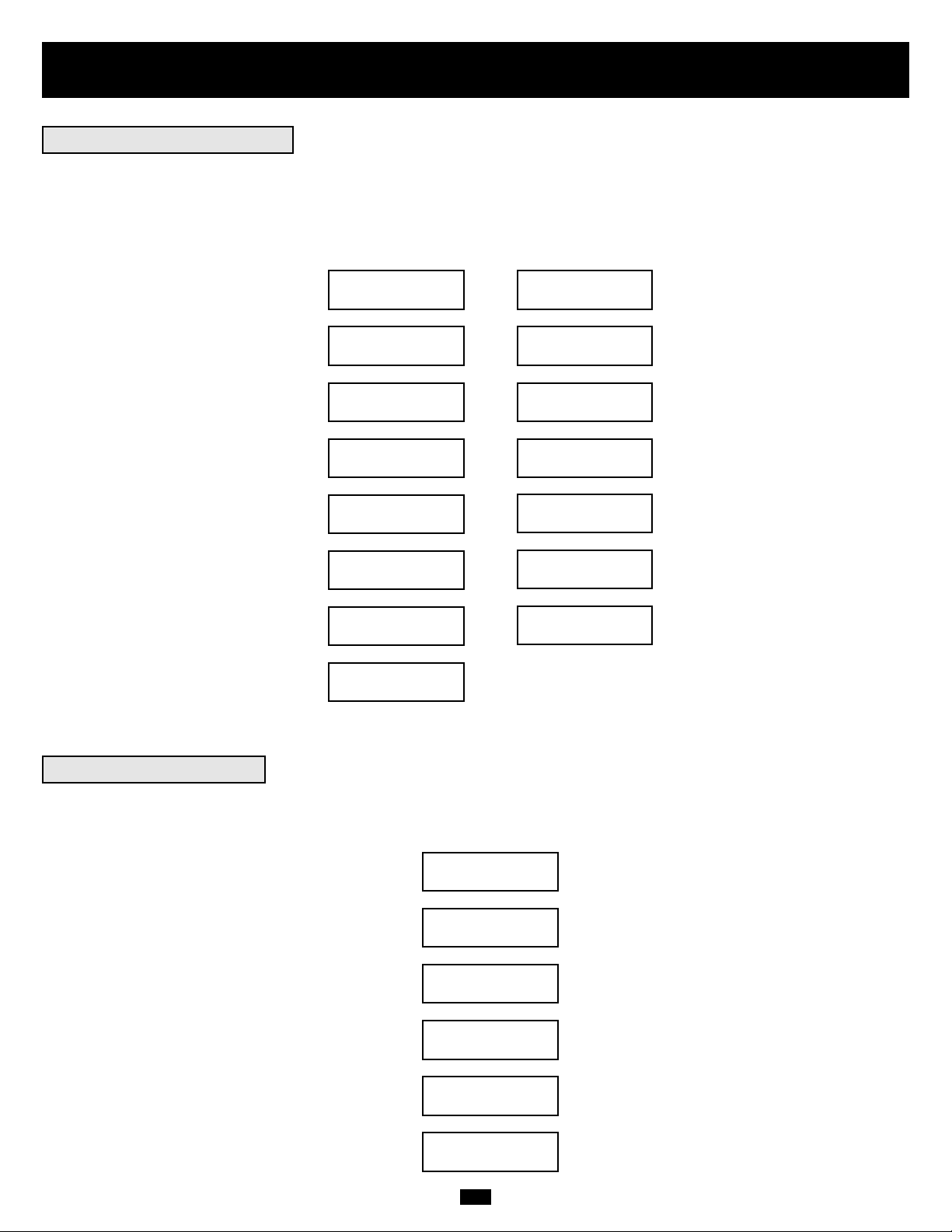
73
DIAGNOSTIC MODE
AC/DC OK
DIAGNOSTIC MODE
TESTING INVERTER
ON BATTERY MODE
LOAD = XXX% X.XXKW
Fonctionnement
Quand vous mettez en fonction le Système d'alimentation continue sans coupure, il entrera le Mode Diagnostic et exécutera un autotest bref durant 15 secondes environ. Les résultats de l'autotest sont indiqués sur l'écran LCD dans la séquence ci-dessous..
DIAGNOSTIC MODE
FREQ OUT = XXHz
DIAGNOSTIC MODE
INPUT AC OK
DIAGNOSTIC MODE
INPUT AC OK
DIAGNOSTIC MODE
BATTERY OK
DIAGNOSTIC MODE
CHARGER OK
DIAGNOSTIC MODE
AC/DC OK
DIAGNOSTIC MODE
TESTING INVERTER
ONLINE MODE
LOAD = XXX% X.XXKW
DIAGNOSTIC MODE
FREQ OUT = XXHz
DIAGNOSTIC MODE
INPUT AC BAD
DIAGNOSTIC MODE
INPUT AC BAD
DIAGNOSTIC MODE
BATTERY OK
M
M
M
M
M
M
M
M
M
M
M
M
M
DEMARRAGE AVEC
ENTRÉE CA
DEMARRAGE A
FROID*
*Remarque: Si le Système d'alimentation continue sans coupure est démarré à froid, sa LED BATTERIE sera allumée.
Si un problème est détecté durant l'autotest, le LCD affichera un message d'erreur. Si votre Système d'alimentation continue sans coupure affiche l'un des
messages suivants dans son LCD, appeler le Support Technique Tripp Lite au (773) 869-1234 pour service.
BAD BATTERY!
CALL FOR SERVICE
CHARGER FAILURE!
CALL FOR SERVICE
AC/DC FAILURE!
CALL FOR SERVICE
INVERTER FAILURE!
CALL FOR SERVICE
OUTPUT FAILURE!
CALL FOR SERVICE
FAN FAILURE!
CALL FOR SERVICE
Autotest de Démarrage
Echec de l'Autotest
SORTIE FREQ MODE
DIAGNOSTIC = XXHz
ENTREE MODE
DIAGNOSTIC CA OK
ENTREE MODE
DIAGNOSTIC CA OK
BATTERIE MODE
DIAGNOSTIC OK
CHARGEUR MODE
DIAGNOSTIC OK
CA/CC MODE
DIAGNOSTIC OK
INVERSEUR TEST MODE
DIAGNOSTIC
CHARGE MODE EN LIGNE
= XXX% X.XXKW
SORTIE FREQ MODE
DIAGNOSTIC = XXHz
CA ENTREE MODE
DIAGNOSTIC MAUVAISE
BATTERIE MODE
DIAGNOSTIC OK
CA/CC MODE
DIAGNOSTIC OK
CHARGEUR MODE
DIAGNOSTIC OK
INVERSEUR TEST
MODE DIAGNOSTIC
CHARGE MODE SUR
BATTERIE = XXX% X.XXKW
MAUVAISE BATTERIE !
APPELER POUR SERVICE
DEFAILLANCE DE
CHARGEUR ! APPELER
POUR SERVICE
DEFAILLANCE CA/CC !
APPELER POUR SERVICE
DEFAILLANCE INVERSEUR !
APPELER POUR SERVICE
DEFAILLANCE SORTIE !
APPELER POUR SERVICE
DEFAILLANCE VENTILATEUR !
APPELER POUR SERVICE
Page 74

74
Fonctionnement
suite
Durant un fonctionnement normal, la première ligne de votre Affichage LCD indique le mode de fonctionnement en cours de votre Système d'alimentation continue sans coupure : En ligne, Economie, Sur Batterie, ou Bypass.
Mode En ligne : Le Système d'alimentation continue sans coupure délivre une alimentation CA quand l'alimentation de service est disponible et passe
immédiatement au mode Sur Batterie (temps de transfert zéro) si l'alimentation CA est interrompue.
Mode Economie : Le Système d'alimentation continue sans coupure délivre une alimentation de haute efficacité quand l'alimentation de service est
disponible et passe rapidement en mode Sur batterie si l'alimentation CA est interrompue.
Mode Sur Batterie : Le Système d'alimentation continue sans coupure délivre une alimentation CA depuis la batterie de secours tant que l'alimentation de
la batterie dure. Il retourne en mode En ligne ou Economie si l'alimentation de service est disponible et se ferme quand l'alimentation de la batterie est épuisée.
Mode Bypass : Le Système d'alimentation continue sans coupure délivre une alimentation CA quand l'alimentation de service est disponible. Le Système
d'alimentation continue sans coupure se ferme si l'alimentation CA est interrompue.
La deuxième ligne de l'Affichage LCD indique les conditions d'alimentation basiques. Appuyer sur les boutons DEFILEMENT pour visualiser rapidement
ces conditions d'alimentation basiques dans la séquence indiquée ci-dessous.
XXXX MODE
LOAD = XXX% X.XXKW
XXXX MODE
IN = XXXV XX.X Hz
XXXX MODE
OUT = XXXV XX.X Hz
XXXX MODE
BATTERY = XXXVDC
M
M
M
Quand il est en mode Sur Batterie, le module d'alimentation du Système d'alimentation continue sans coupure émettra un bip pour vous informer qu'il utilise
l'alimentation de la batterie pour supporter l'équipement connecté. Si ses batteries connectées sont à plus de la moitié de leur capacité, il émettra un bip
toutes les deux secondes. Si ses batteries connectées sont au-dessous de la moitié de leur capacité, il émettra deux bips par seconde. Si ses batteries connectées sont presque épuisées, le module d'alimentation du Système d'alimentation continue sans coupure émettra un bip continuel.
Pour arrêter l'Alarme Sur Batterie, appuyer sur le bouton “ON/SILENCE”.
Quand le Système d'alimentation continue sans coupure détecte une surcharge de sortie, son LCD passera à l'affichage suivant :
Le Système d'alimentation continue sans coupure commencera alors un compte à rebours. Si le Système d'alimentation continue sans coupure est toujours
surchargé à la fin du compte à rebours, le Système d'alimentation continue sans coupure passera automatiquement au Mode Bypass pour protéger son
inverseur. La durée du compte à rebours varie avec l'importance de la surcharge, comme suit :
OVERLOAD!
LOAD = XXX% X.XXKW
Condition de Surcharge Durée du Compte à rebours
102% - 125% 1 minute
125% - 150% 30 secondes
>150% Immédiat
M
M
L
L
L
Fonctionnement Normal
Alarme Sur Batterie
Messages de Surcharge
CHARGE MODE
XXXX = XXX% X.XXKW
MODE ENTREE
XXXX = XXXV XX.X Hz
MODE SORTIE
XXXX = XXXV XX.X Hz
MODE BATTERIE
XXXX = XXXVCC
OVERLOAD!
LOAD = XXX% X.XXKW
Page 75

75
En Mode Bypass, le Système d'alimentation continue sans coupure contrôle sa tension d'entrée et transmet cette alimentation d'entrée à l'équipement connecté. Le Système d'alimentation continue sans coupure n'assurera pas d'alimentation de batterie de secours en Mode Bypass.
Si la tension de sortie dévie de l'échelle acceptable (entre 15% supérieure et 20% inférieure à la valeur nominale), le Système d'alimentation continue sans
coupure affiche la condition sur son LCD et arrête de délivrer l'alimentation de sortie à sa charge. Si les niveaux d'alimentation retournent à un niveau
acceptable, le Système d'alimentation continue sans coupure reprend la délivrance d'alimentation à la charge, et son LCD indique que la tension de sortie
était trop élevée ou trop basse à un moment, mais est retournée à sa valeur nominale.
>15% Plus Elevée que la
Valeur Nominale
>20% Plus Basse que la
Valeur Nominale
Etait Trop Elevée, Maintenant
Valeur Nominale
Etait Trop Basse, Maintenant
Valeur Nominale
CONDITIONS DE
TENSION BYPASS
MESSAGES
D'AFFICHAGE LCD
Votre Système d'alimentation continue sans coupure se fermera et le LCD affichera un message s'il détecte une des conditions suivantes.
Remarque : Durant toutes ces conditions, les LED “Entrée”, “Sortie” et “Bypass” seront allumées.
Surcharge Prolongée
Court-circuit Sortie
Commande Fermeture à
Distance (Via DB9)
Commande Fermeture à
Distance (Via EPO)
CONDITIONS DE
FERMETURE
MESSAGES D'AF-
FICHAGE LCD
Défaillances Internes
NO OUTPUT BYPASS
AC TOO HI
NO OUTPUT BYPASS
AC TOO LO
BYPASS MODE BYPASS
AC WAS HI
BYPASS MODE BYPASS
AC WAS LO
SHUT DOWN
OVERLOAD XXX%
SHUT DOWN
O/P SHORT CIRCUIT
SHUT DOWN
REMOTE COMMAND
SHUT DOWN
EMERGENCY STOP!
SHUT DOWN
+ DC BUS HIGH
SHUT DOWN
+ DC BUS LOW
SHUT DOWN
- DC BUS HIGH
SHUT DOWN
- DC BUS LOW
SHUT DOWN
OVERTEMPERATURE
Messages de Bypass
Messages de Fermeture
Fonctionnement
suite
PAS DE SORTIE CA
BYPASS TROP HAUT
PAS DE SORTIE CA
BYPASS TROP BAS
CA BYPASS MODE BYPASS
ETAIT HAUT
CA BYPASS MODE BYPASS
ETAIT BAS
SURCHARGE
FERMETURE XXX%
FERMETURE
COURT-CIRCUIT O/P
COMMANDE A DISTANCE
FERMETURE
ARRET D'URGENCE
FERMETURE !
FERMETURE
+ BUS CC HAUT
FERMETURE
+ BUS CC BAS
FERMETURE
- BUS CC HAUT
FERMETURE
- BUS CC BAS
FERMETURE TEMPERATURE
TROP ELEVEE
Page 76

76
Entreposage, Entretien, Garantie et Assurance
Avant d'entreposer votre UPS, éteignez-le complètement. Si vous entreposez votre UPS pendant une longue période, rechargez les piles UPS pendant 4-6
heures une fois tous les trois mois. Remarque : une fois votre UPS branché à l'alimentation de service, il commencera automatiquement à recharger ses
piles. Si vous laissez les piles UPS déchargées pendant une longue période, elles souffriront d'une perte de capacité permanente.
Votre système UPS SmartOnline est couvert par une garantie limitée de 2 ans décrite ci-dessous. Une gamme de programmes de garantie étendue et de
service sur le site est également disponible chez Tripp Lite. Pour de plus amples informations sur le service, contactez le soutien à la clientèle de Tripp Lite
au numéro (773) 869-1234.
Avant de retourner votre UPS pour entretien, procédez comme suit :
1. Révisez les instructions d'installation et de fonctionnement de ce manuel pour vous assurer que le problème ne provient pas d'une mauvaise interprétation des instructions. Vérifiez également que le(s) disjoncteur(s) du système UPS ne sont pas déclenchés. C'est la cause la plus courante de demande de
service et on peut facilement y remédier en se conformant aux instructions de remise en état de ce manuel.
2. Si le problème se poursuit, ne contactez pas et ne retournez pas le UPS au vendeur. Appelez plutôt Tripp Lite au numéro (773) 869-1233. Un technicien
de service vous demandera le numéro du modèle du UPS, le numéro de série et la date d'achat et essaiera de corriger le problème par téléphone.
3. Si le problème demande réparation, le technicien vous fournira un numéro d'autorisation de matériel retourné (RMA), lequel est obligatoire lors des réparations. Il vous expliquera également les procédures adéquates d'emballage et d'expédition. Tout dommage (direct, indirect, spécial, accessoire ou consécutif) au UPS à s'être produit durant l'expédition à Tripp Lite ou à un centre autorisé de Tripp Lite n'est pas couvert par la garantie. Les systèmes UPS
expédiés à Tripp Lite ou à un centre de service autorisé Tripp Lite doivent être envoyés tout frais de transport pré-payés. Inscrivez le no. RMA à l'extérieur
du paquet. Si le système UPS est encore dans sa période de garantie de 2 ans, incluez une copie de votre reçu d'achat. Retournez le UPS pour réparation
par transporteur assuré à l'adresse qui vous a été donnée par le technicien de service de Tripp Lite.
TRIPP LITE garantit que ses produits incluant les batteries sont exempts de tous défauts de matériels et de vices de fabrication pendant une période de deux ans à partir de la date de l'achat
initial. Après les 90 jours suivant la date d'achat, les obligations de TRIPP LITE dans le cadre de cette garantie sont limitées au remplacement des pièces de ces produits défectueux.Pour obtenir
des services dans le cadre de cette garantie, vous devez appeler TRIPP LITE ou un centre de services TRIPP LITE agréé. Les produits doivent être retournés à TRIPP LITE ou un centre de
services TRIPP LITE agréé avec les frais d'expédition prépayés et doivent être accompagnés par une brève description du problème rencontré et la preuve de la date et du lieu de l'achat. Cette
garantie ne s'applique pas aux équipements qui ont été endommagés par accident, négligence ou application erronée ou qui ont été changés ou modifiés d'une manière quelconque. Cette garantie
s'applique seulement à l'acheteur original qui doit avoir enregistré correctement le produit dans les 10 jours suivant l'achat.
Les garanties pour tous les suppresseurs de surtension TRIPP LITE sont nulles et non avenues si ils ont été connectés à la sortie de tout Système d'alimentation continue sans coupure. Les
garanties de tous les Systèmes d'alimentation continue sans coupure TRIPP LITE sont nulles et non avenues si un suppresseur de surtension a été connecté à ses prises de sortie.
SAUF SI STIPULE DANS LA PRESENTE, TRIPP LITE N'ACCORDE AUCUNES GARANTIES, EXPRESSES OU IMPLICITES, INCLUANT LES GARANTIES DE COMMERCIALISATION ET
ADAPTATION POUR UN BUT PARTICULIER. Certains états ne permettent pas la limitation ou l'exclusion des garanties implicites ; en conséquence, le(s) limitation(s) ou exclusion(s) peuvent ne
pas s'appliquer à l'acheteur.
SAUF SI STIPULE CI-DESSUS, EN AUCUN CAS TRIPP LITE NE SERA RESPONSABLE POUR TOUS DOMMAGES DIRECTS, INDIRECTS, SPECIAUX, ACCIDENTELS OU PROVOQUES
RESULTANT DE L'UTILISATION DE CE PRODUIT, MEME SI INFORME DE LA POSSIBILITE D'UN TEL ENDOMMAGEMENT. En particulier, TRIPP LITE n'est pas responsable de tous coûts,
tels que perte de profits ou revenus, perte d'équipement, perte d'utilisation d'équipement, perte de logiciel, perte de données, coûts de substituts, réclamations de tierces parties, ou autre.
La politique de TRIPP LITE est celle d'une amélioration continuelle. Les spécifications peuvent être modifiées sans préavis.
Tripp Lite garantit, pour la durée de vie du produit, (au choix de Tripp Lite) de réparer ou remplacer (sur une base pro rata) l'équipement connecté directement qui est endommagé en raison de
transitoires d'alimentation lors de connexion correcte aux produits Tripp Lite offrant la Police d'Assurance de Durée de Vie Finale. Les transitoires d'alimentation incluent les pointes et les surtensions sur les lignes d'alimentation CA, données ou téléphone pour lesquelles les produits Tripp Lite ont été conçus pour protection (comme reconnu par les normes industrielles).
Transitoires de Ligne d'Alimentation : Pour réclamer des dommages et intérêts, le produit Tripp Lite doit être branché à une sortie correctement câblée et mise à la terre. Aucun cordon de rallonge
ou autres connexions électriques ne doivent être utilisés. L'installation doit être conforme à tous les codes électriques et de sécurité applicables établis par le National Electrical Code (NEC). Sauf
si stipulé ci-dessus, cette garantie ne couvre pas tout endommagement d'un équipement électronique connecté correctement résultant d'une cause autre qu'un "transitoire d'alimentation CA". Si
l'utilisateur se conforme à toutes les stipulations ci-dessus, Tripp Lite réparera ou remplacera (au choix de Tripp Lite) l'équipement à la valeur spécifiée (Voir Limites de Police d'Assurance de
Durée de Vie Finale). Aucune couverture n'est accordée pour tout endommagement provenant de lignes de téléphone ou de données, sauf si elles sont protégées séparément, comme décrit cidessous.
Transitoires de Lignes de Téléphone et de Données : Tripp Lite réparera ou remplacera l'équipement connecté directement qui est endommagé par des transitoires sur les lignes de téléphone
et/ou de données seulement quand toutes ces voies sont protégées par un(des) produit(s) de protection Tripp Lite et quand la ligne d'alimentation CA (service) est simultanément protégée par
un appareil de protection d'alimentation Tripp Lite (Système d'alimentation continue sans coupure, suppresseur de surtension ou dispositif de conditionnement de ligne) avec la couverture
d'Assurance de Durée de Vie Finale. Les dispositifs connectés de lignes de téléphone et/ou de données supplémentaires en aval doivent avoir leurs propres appareils de protection de lignes de
téléphone et/ou de données.
Les limites dollar de remboursement seront égales à celles de l'appareil de protection d'alimentation Tripp Lite. La couverture est exclue si un environnement approprié pour l'appareil de protection n'est pas assuré, incluant, mais sans s'y limiter, l'absence d'une mise à la terre de sécurité adéquate. L'équipement de service téléphonique doit aussi inclure un dispositif de "protection primaire" installé et fonctionnant correctement à l'entrée du service téléphonique (ces dispositifs sont normalement ajoutés durant l'installation de la ligne téléphonique).
Toutes les garanties ci-dessus sont nulles et non avenues si le produit Tripp Lite a été incorrectement installé, changé ou modifié d'une manière quelconque, ou si l'équipement connecté n'a pas
été utilisé dans des conditions de fonctionnement normales ou conformément à toutes étiquettes ou instructions. Toutes les réclamations de dommages et intérêts dans le cadre de cette garantie
doivent être présentées par écrit à Tripp Lite dans les 30 jours suivant le fait, sinon la demande ne sera pas prise en considération. Cette garantie n'inclut pas les dommages résultant d'accident
ou d'utilisation erronée, et s'applique seulement à l'utilisation intérieure (Etats-Unis & Canada) de ces produits.
Tripp Lite se réserve le droit de déterminer si l'endommagement à l'équipement connecté est dû à un mauvais fonctionnement du produit Tripp Lite en demandant que l'équipement en question
soit envoyé à Tripp Lite pour examen. Cette police s'ajoute, seulement dans la mesure nécessaire, à celle de toutes autres sources de couverture d'équipement connecté, incluant, mais sans s'y
limiter, toute garantie de fabricant et/ou toutes garanties étendues.
SAUF SI STIPULE DANS LA PRESENTE, TRIPP LITE N'ACCORDE AUCUNES GARANTIES, EXPRESSES OU IMPLICITES, INCLUANT LES GARANTIES DE COMMERCIALISATION ET
ADAPTATION POUR UN BUT PARTICULIER. Certains états ne permettent pas la limitation ou l'exclusion des garanties implicites ; en conséquence, le(s) limitation(s) ou exclusion(s) peuvent ne
pas s'appliquer à l'acheteur.
SAUF SI STIPULE CI-DESSUS, EN AUCUN CAS TRIPP LITE NE SERA RESPONSABLE POUR TOUS DOMMAGES DIRECTS, INDIRECTS, SPECIAUX, ACCIDENTELS OU PROVOQUES
RESULTANT DE L'UTILISATION DE CE PRODUIT, MEME SI INFORME DE LA POSSIBILITE D'UN TEL ENDOMMAGEMENT. En particulier, TRIPP LITE n'est pas responsable de tous coûts,
tels que perte de profits ou revenus, perte d'équipement, perte d'utilisation d'équipement, perte de logiciel, perte de données, coûts de substituts, réclamations de tierces parties, ou autre. La
couverture ne s'applique pas non plus aux équipements médicaux et industriels connectés.
Pour bénéficier de services dans le cadre de cette garantie, vous devez être l'acheteur/l'utilisateur d'origine du produit en question. Vous devez obtenir un numéro d'Autorisation de Retour de
Matériel (RMA) de Tripp Lite. Les produits doivent être retournés à Tripp Lite avec les frais de transport prépayés et doivent être accompagnés par une brève description du problème rencontré
et la preuve de la date et du lieu d'achat.
Entreposage
Garantie Limitée à 2 Ans
Police d'Assurance de Durée de Vie Finale
(Valide aux Etats-Unis et au Canada SEULEMENT)
Entretien
Page 77

77
Spécifications (modèles avec transformateur)
Les modèles énumérés ci-dessous comprennent un module d'alimentation, un ou deux modules à piles et un module de transformateur. Tous
les modèles énumérés ci-dessous comprennent les trois types de modules à l'exception de l'option 5kVA où le module de transformateur (modèle : SU5000XFMRT2U) est vendu séparément du module d'alimentation et du module à piles (modèle :
SU5000RT3UHV). Selon le modèle commandé, un module à piles peut être compris ; il peut être extensible ou non. Tous les modules d'al-
imentation toutefois sont entièrement compatibles avec les modules à piles de Tripp Lite (modèle Tripp Lite no. BP240V10RT-3U, vendu
séparément) si une phase d'exécution étendue est requise.
Information sur le modèle
No(s) de modèle SU5000RT3UHV & SU5000XFMRT2U* SU6000RT3U SU6000RT3UXR SU10KRT3U
L'ensemble comprend :
Module d'alimentation (modèle : SU5000RT3UPM; (modèle : SU6000RT3UPM; (modèle : SU6000RT3UPM; (modèle : SU10KRT3UPM;
série : AGPS5124) série : AGSU60003U) série : AGSU60003U) série : AGSU100003U)
Module à piles no. 1 (modèle : BP240V5RT2U; (modèle : BP240V7RT3U; (modèle : BP240V10RT3U; (modèle : BP240V10RT3U;
série: AGBP5161) série: AGBP240V7RT3U) série: AGBP240V7RT3U) série: AGBP240V7RT3U)
Non extensible Non-extensible EXTENSIBLE EXTENSIBLE
Module à piles no. 2 N/A N/A (modèle : BP240V7RT3U; N/A
série: AGBP240V7RT3U)
Non-extensible
Module de transformateur *Module de transformateur (modèle : SU6000XFMRRT3U; (modèle : SU6000XFMRRT3U; (modèle : SU10KXFMRRT3U;
Vendu séparément ! série: AGSM6000SDRT3U) série: AGSM6000SDRT3U) série: AGSM10KSDRT3U)
(modèle : SU5000XFMRT2U;
série: AGc.a.5125)
Approbations : tous les modules d'alimentation (UL, cUL, NOM, CE, GOST, SASO, IRAM, FCC catégorie A). Tous les modules à piles (UL, cUL, NOM). Tous les modules de transformateur (UL,
cUL, NOM, FCC catégorie A)
Entrée
Type de connexion d'entrée 10 pi. cordon avec prise L6-30P câblage câblage câblage
Plage de tension d'entrée 156V~276V monophasé 156V~276V monophasé 156V~276V monophasé 156V~276V monophasé
Tension d'entrée du module 200/208/220/230/240V c.a. 200/208/240V c.a. 200/208/240V c.a. 200/208/240V c.a.
Fréquence d'entrée 50/60 Hz ± 3 Hz 50/60 Hz ± 3 Hz 50/60 Hz ± 3 Hz 50/60 Hz ± 3 Hz
Courant d'entrée 20A 22.6A 22.6A 40A
Courant d'appel <150A <150A <150A <200A
Facteur d'alimentation (charge pleine) >0.97 >0.97 >0.97 >0.97
Efficacité (charge pleine/en ligne) >87% >87% >87% >88%
Disjoncteur du module d'alimentation N/A 40A (2 pôle) 40A (2 pôle) 63A (2 pôle)
Disjoncteur du module de transformateur N/A 40A (2 pôle) 40A (2 pôle) 63A (2 pôle)
Sortie
VA 5000 6000 6000 10000
Watts (facteur d'alimentation : 0,7) 3500 4200 4200 7000
Type de connexion de sortie 4 prises sur le module d'alimentation câblage câblage câblage
(2 L6-20R et 2 L6-30R) et
12 prises sur le transformateur
module (5-15/20R)
Forme d'onde (en ligne) sinusoïdale sinusoïdale sinusoïdale sinusoïdale
Forme d'onde (en ligne) sinusoïdale sinusoïdale sinusoïdale sinusoïdale
Tension d'entrée (RMS) 120*/200/208/220/230/240V c.a. 100/120/200/208/240V c.a. 100/120/200/208/240V c.a. 100/120/200/208/240V c.a.
Fréquence de sortie 50/60 Hz (± 0.2 Hz sur pile) 50/60 Hz (± 0.2 Hz sur pile) 50/60 Hz (± 0.2 Hz sur pile) 50/60 Hz (± 0.2 Hz sur pile)
Régulation de tension ±3% ±3% ±3% ±3%
Max. Distorsion harmonique
(charge linéaire entière) <3% <3% <3% <3%
(charge entière non-linéaire) <6% <6% <6% <6%
Capacités de surtension 102% (continu) 102% (continu) 102% (continu) 102% (continu)
102%~125% (1 min.) 102%~125% (1 min.) 102%~125% (1 min.) 102%~125% (1 min.)
125%~150% (30 sec.) 125%~150% (30 sec.) 125%~150% (30 sec.) 125%~150% (30 sec.)
>150% (immédiat) >150% (immédiat) >150% (immédiat) >150% (immédiat)
Capacité de court-circuit 90A 90A** 90A** 160A**
Disjoncteur du module d'alimentation 20A (2 pôle) 40A 63A 63A
Disjoncteur du module de transformateur* quatre 20A (pôle simple) 30A (3 pôle) 63A (3 pôle) 63A (3 pôle)
Facteur de crête 3:1 3:1 3:1 3:1
* Le module du transformateur est vendu séparément avec l'option 5kVA. ** La capacité de court circuit à 1ø 2W 120V pour le SU6000RT3U et le SU6000RT3UXR est supérieure à 180A et pour le SU10KRT3U,
elle est supérieure à 320A.
Opération
Temps de transfert en ligne
(Ligne à pile, pile à ligne) 0 ms. 0 ms 0 ms 0 ms
Bruit audible (charge @ 1 m) <50 dBA <50 dBA <55 dBA <55 dBA
Indicateurs
Comprend un afficheur et des témoins lumineux (entrée), PILE, C.A./C.C., C.C./C.A. CONTOURNEMENT, ENTRÉE/SORTIE (sortie)).
Communications
Comprend un connecteur femelle RS-232 DB9, un connecteur femelle à contact sec DB9 et une fente à accessoire.
Spécifications physiques
Dimensions de l'appareil (H x W x D)
Module d'alimentation 5,25 (3U) x 17,5 x 26 po. 5,25 (3U) x 17,5 x 22,5 po. 5,25 (3U) x 17,5 x 22,5 po. 5,25 (3U) x 17,5 x 22,5 po.
[13,4 x 44,5 x 66 cm.] [13,4 x 44,5 x 57,2 cm.] [13,4 x 44,5 x 57,2 cm.] [13,4 x 44,5 x 57,2 cm.]
Module de transformateur* 3,5 (2U) x 17,5 x 20,75 in. 5,25 (3U) x 17,5 x 26 po. 5,25 (3U) x 17,5 x 26 po. 5,25 (3U) x 17,5 x 26 po.
[8,9 x 44,5 x 52,7 cm.] [13,4 x 44,5 x 66,1 cm.] [13,4 x 44,5 x 66,1 cm.] [13,4 x 44,5 x 66,1 cm.]
Module à piles no. 1 3,5 (2U) x 17,5 x 20,75 in. 5,25 (3U) x 17,5 x 22,5 po. 5,25 (3U) x 17,5 x 22,5 po. 5,25 (3U) x 17,5 x 22,5 po.
[8,9 x 44,5 x 52,7 cm.] [13,4 x 44,5 x 57,2 cm.] [13,4 x 44,5 x 57,2 cm.] [13,4 x 44,5 x 57,2 cm.]
Module à piles no. 2 (si applicable) N/A N/A 5,25 (3U) x 17,5 x 22,5 po. N/A
[13,4 x 44,5 x 57,2 cm.]
Poids à l'expédition
Module d'alimentation 58 lbs. [27 kg.] 58 lbs. [27 kg.] 58 lbs. [27 kg.] 68 lbs. [31 kg.]
Module de transformateur* 60 lbs. [28 kg.] 124 lbs. [57 kg.] 124 lbs. [57 kg.] 124 lbs. [57 kg.]
Module à piles no. 1 95 lbs. [43 kg.] 160 lbs. [73 kg.] 160 lbs. [73 kg.] 160 lbs. [73 kg.]
Module à piles no. 2 (si applicable) N/A N/A 160 lbs. [73 kg.] N/A
* Le module du transformateur est vendu séparément avec l'option 5kVA.
Page 78

78
Spécifications (modèles sans transformateur)
Les modèles énumérés ci-dessous comprennent un module d'alimentation et un module à piles. Selon le modèle commandé, un module à
piles peut être compris ; il peut être extensible ou non. Tous les modules d'alimentation toutefois sont entièrement compatibles avec les
modules à piles de Tripp Lite (modèle Tripp Lite no. BP240V10RT-3U, vendu séparément) si une phase d'exécution étendue est requise.
Information sur le modèle
modèle no(s) SU5000RT3UHV SU6000RT3UHV SU10KRT3UHV
L'ensemble comprend :
Module d'alimentation (modèle : SU5000RT3UPM; (modèle : SU6000RT3UPM; (modèle : SU10KRT3UPM;
série: AGPS5124) série: AGSU60003U) série: AGSU100003U)
Module à piles no. 1 (modèle : BP240V5RT2U; série: AGBP5161) (modèle : BP240V7RT3U; (modèle : BP240V10RT3U;
Non-extensible série: AGBP240V7RT3U) série: AGBP240V7RT3U)
Non-extensible EXTENSIBLE
Approbations : tous les modules d'alimentation (UL, cUL, NOM, CE, GOST, SASO, IRAM, FCC catégorie A). Tous les modules à piles (UL, cUL, NOM).
Entrée
Type de connexion d'entrée 10 pi. cordon avec prise L6-30P câblage câblage
Plage de tension d'entrée 156V~276V monophasé 156V~276V monophasé 156V~276V monophasé
Tension d'entrée du module 200/208/220/230/240V c.a. 200/208/240V c.a. 200/208/240V c.a.
Fréquence d'entrée 50/60 Hz ± 3 Hz 50/60 Hz ± 3 Hz 50/60 Hz ± 3 Hz
Courant d'entrée 20A 22,6A 22,6A 40A
Courant d'appel <150A <150A <200A
Facteur d'alimentation (charge pleine) >0,97 >0,97 >0,97
Efficacité (charge pleine/en ligne) >87% >87% >88%
Disjoncteur du module d'alimentation N/A 40A (2 pôle) 63A (2 pôle)
Sortie
VA 5000 6000 10000
Watts (facteur d'alimentation : 0,7) 3500 4200 7000
Type de connexion de sortie 4 prises câblage câblage
(2 L6-20R et 2 L6-30R)
Forme d'onde (en ligne) sinusoïdale sinusoïdale sinusoïdale
Forme d'onde (sur pile) sinusoïdale sinusoïdale sinusoïdale
Tension de sortie (RMS) 200/208/220/230/240V c.a. 200/208/240V c.a. 200/208/240V c.a.
Fréquence de sortie 50/60 Hz (± 0.2 Hz à la pile) 50/60 Hz (± 0,2 Hz sur pile) 50/60 Hz (± 0.2 Hz sur pile)
Régulation de tension ±3% ±3% ±3%
Max. Distorsion harmonique
(charge linéaire entière) <3% <3% <3%
(charge entière non-linéaire) <6% <6% <6%
Capacités de surtension 102% (continu) 102% (continu) 102% (continu)
102%~125% (1 min.) 102%~125% (1 min.) 102%~125% (1 min.)
125%~150% (30 sec.) 125%~150% (30 sec.) 125%~150% (30 sec.)
>150% (immédiat) >150% (immédiat) >150% (immédiat)
Capacité de court-circuit 90A 90A 160A
Disjoncteur du module d'alimentation 20A (2 pôle) 40A 63A
Facteur de crête 3:1 3:1 3:1
Opération
Temps de transfert en ligne
(Ligne à pile, pile à ligne) 0 ms. 0 ms 0 ms
Bruit audible (charge @ 1 m) <50 dBA <50 dBA <55 dBA
Indicateurs
Comprend un afficheur et des témoins lumineux (entrée), PILE, C.A./C.C., C.C./C.A. CONTOURNEMENT, ENTRÉE/SORTIE (sortie)).
Communications
Comprend un connecteur femelle RS-232 DB9, un connecteur femelle à contact sec DB9 et une fente à accessoire.
Spécifications physiques
Dimensions de l'appareil (H x W x D)
Module d'alimentation 5,25 (3U) x 17,5 x 26 po. 5,25 (3U) x 17,5 x 22,5 po. 5,25 (3U) x 17,5 x 22,5 po.
[13,4 x 44,5 x 66 cm.] [13,4 x 44,5 x 57,2 cm.] [13,4 x 44,5 x 57,2 cm.]
Module à piles 3,5 (2U) x 17,5 x 20,75 po. 5,25 (3U) x 17,5 x 22,5 po. 5,25 (3U) x 17,5 x 22,5 po.
[8,9 x 44,5 x 52,7 cm.] [13,4 x 44,5 x 57,2 cm.] [13,4 x 44,5 x 57,2 cm.]
Poids à l'expédition
Module d'alimentation 58 lbs. [27 kg.] 58 lbs. [27 kg.] 68 lbs. [31 kg.]
Module à piles 95 lbs. [43 kg.] 160 lbs. [73 kg.] 160 lbs. [73 kg.]
AVIS D'INTERFÉRENCE FCC RADIO/TV
Remarque : cet équipement a été mis à l'essai et trouvé conforme aux limites pour un dispositif numérique de catégorie B, en vertu de la partie 15 des règlements FCC. Ces limites sont conçues pour procurer une protection raisonnable contre une interférence nuisible lorsque en opération dans un environnement commercial. Cet équipement génère,
utilise et peut diffuser des fréquences radio et, s'il n'est pas installé et utilisé conformément au manuel d'instructions, peut causer des interférences avec les communications
radio. L'opération de cet équipement est susceptible de causer une interférence nuisible auquel cas l'utilisateur devra corriger l'interférence à ses frais. L'utilisateur doit utiliser des
câbles et connecteurs armés avec ce produit. Tout changement ou modification à ce produit non expressément approuvée par la partie responsable de la conformité pourrait
annuler l'autorité de l'utilisateur à faire fonctionner l'équipement.
Numéros d'identification de conformité aux règlements
À des fins de certification et d'identification de conformité aux règlements, votre produit Tripp Lite a reçu un numéro de série unique. Ce numéro se retrouve sur la plaque signalétique du produit, avec les inscriptions et informations d'approbation requises. Lors d'une demande d'information de conformité pour ce produit, utilisez toujours le numéro de
série. Il ne doit pas être confondu avec le nom de la marque ou le numéro de modèle du produit.
Page 79

Инструкция владельца
1111 W. 35th Street Chicago, IL 60609 USA (1111 Восточная 35я улица, Чикаго, Иллинойс 60609 США)
Обслуживание/поддержка клиентов: (773) 869-1234 • Обслуживание аппликаций: • (773) 869-1236 www.tripplite.com
Интеллектуальная собственность © 2004 Tripp Lite. Все права защищены.
SmartOnline™однофазный 6k ВА и 10kВА
Разумные, онлайновые системы Источникa Бесперебойного Питания (ИБП)
(конфигурация башни)
Для всех системных модулей ИБП (блок питания, изолирующий трансформаторный модуль и батареи),
проданных либо отдельно, либо вместе. Некоторые системные модули ИБП могут включать отдельную
инструкцию или предостережения, которые должны быть использованы совместно с этой инструкцией.
Важная инструкция по безопасности
Установка
Соединение
Свойства
Правила пользования
Сервис/Гарантия
Спецификации
English/Español/Français
80
81
83
87
94
97
98
1/27/53
Дополнительное Соединение
91
Сеть ВКЛЮЧЕН/ВЫКЛЮЧЕН
92
Правила Работы Вручную
93
Page 80

80
Важная инструкция по безопасности
СОХРАНИТЕ ЭТИ ИНСТРУКЦИИ. Этот документ содержит инструкции и предупреждения, которым рекомендуется
следовать во время инсталяции, использования и хранения ИБП систем Tripp Lite SmartOnline башенной конфигурации, а
также их батарей.
Предупреждение по размещению ИБП
• Установите ваш ИБП в помещении, в сухом прохладном месте, вне попадания проводящих загрязнителей, пыли или
прямого солнечного света.
• Установите ваш ИБП в удобном месте. Ваш ИБП предельно тяжелый; будьте осторожны передвигая или поднимая его.
• Пользуйтесь ИБП только при комнатных температурах между 32° F и 104° F (между 0° C и 40° C). Для лучших
результатов, поддерживайте комнатную температуру между 62° F и 84° F (между 17° C и 29° C).
• Оставьте адекватное пространство со всех сторон ИБП для вентиляции.
• Не устанавливайте ИБП возле магнитных средств хранения информации, так как это может привести к потере
информации.
Предупреждение по подсоединению ИБП
• Блок питания для этого прибора должен быть однофазным в соответствии с биркой на приборе.
Он также должен быть правильно заземл¸н
• Не используйте ИБП системы Tripp Lite для оборудования, поддерживающего жизненные функции, чтобы избежать
ситуации, в которой неисправность или поломка системы ИБП Tripp Lite может стать причиной поломки или работы с
перебоями оборудования, поддерживающего жизненные функции
• Подсоедините ваш блок питания ИБП и/или терминал изолирующего трансформатора к проводнику электрода.
• ИБП подсоединяется к источнику постоянного тока (батарея). Выводы могут быть живыми, когда ИБП не подсоедин¸н к
источнику переменного тока.
Предупреждение по обслуживанию
• Ваш блок питания, изолирующий трансформаторный модуль и батарея ИБП не требуют регулярного ухода. Не
открывайте ваш ИБП.Внутри ИБП нет частей, требующих ремонта.
Предупреждение о батарее
• Не используйте ваш ИБП без подсоединения к внешней батарее.
• Подсоедините только модуль батареи Tripp Lite к соединителю внешней батареи ИБП.
• Батареи ИБП подлежат переработке. Обратитесь к местным сводам правил по переработке, для информации в пределах
США позвоните по телефонному номеру 1-800-SAV-LEAD (1-800-8-228-5323) для того, чтобы получить информацию по
переработке. ВНИМАНИЕ: Не бросайте батареи в огонь- это может привести к взрыву.
• Поскольку батареи представляют риск электрического шока и ожога в результате короткого замыкания, батареи должны
заменяться только обученным персоналом, соблюдающим надлежащие меры предосторожности. Обратитесь к
инструкциям, перед тем как тем как приступить. Снимите часы, кольца, и другие металлические предметы. Используйте
инструменты с изолированными рукоятками. Оденьте резиновые перчатки и ботинки. Не кладите инструменты или
металлические детали на батарею. Не замыкайте батарею посторонними предметами. Отсоедините источник
напряжения, перед тем как соединять или отсоединять вводы батареи. Определите, заземлена ли батарея. Если батарея
заземлена, удалите источник заземления. Контакт с любой частью заземл¸нной батареи может привести к
электрическому шоку. Вероятность такого шока будет снижена, такие основания удаляются во время инсталяции и
ремонта.
• Не открывайте и не разбирайте батарею. Электролит вреден для кожи и глаз, и может быть токсичен
• Только санкционированный персонал может менять предохранители. Перегоревшие предохранители следует менять
только на предохранители того же номера и типа.
• Сервис и ремонт должен производиться только обученным персоналом. Во время обслуживания ИБП должен быть
отключ¸н или вручную переключен на трансформатор. Внимание: внутри этого блока существует потенциально
смертельный уровень напряжения, если батарея подсоединена.
• Не соединяйте и не разъединяйте модуль батареи, пока ИБП работает от батареи или когда модуль трансформатора не
переключен на перемычку (если ваша система ИБП предполагает модуль трансформатора).
• Во время замены батареи ваш ИБП не сможет обеспечить питание, в случае отключения электричества.
Page 81

81
Установка (Стеллаж)
1
Установка 4-контактного стеллажа
1
2
3
A
B
C
F
E
G
4
H
Соедините два сегмента каждой полки используя прилагающиеся винты
и гайки . Не закручивайте винты плотно,чтобы полки можно было
приспособить на следующем этапе.
Адаптируйте каждую полку, чтобы она подошла к стеллажу, затем
прикрепите полки внизу вашего стеллажа при помощи винтов и гаек .
Внимание: уголки должны быть обращены вовнутрь. Затяните гайки,
чтобы соединить сегменты полки .
Присоедините закрепители к лицевой стороне отверстий вашего
оборудования используя предложенные винты . Закрепители должны
быть лицевой стороной впер¸д.
При помощи ассистента, поднимите ваш прибор и поставьте его на полку.
Присоедините ваше оборудование к стеллажу при помощи винтов и гаек
(обеспеченный пользователем) через закрепители и рельсы стеллажа.
Чтобы смонтировать ваше оборудование на 2х основном стеллаже, вы должны
приобрести 2х основный инсталяционный набор от Tripp Lite (модель: 2
POSTRMKIT, прода¸тся отдельно) для каждого установленного модуля.
Обратитесь к инсталяционному справочнику владельца за инструкциями к
монтажу.
H
GF
E
D
C
B
A
4
Вмонтируйте ваше оборудование в стеллаж на 4х или 2х основах или стеллаж с полкой. Пользователь должен определить
пригодность приборов и процесс перед установкой. Если приборы и инструкция не подходят для вашей аппликации,
обратитесь к изготовителю вашего стеллажа или корпуса стеллажа. Инструкции, описанные в этом документе, пригодны для
стандартного стеллажа и типов корпуса стеллажа и могут соответствовать не всем приложениям.
2
3
Установка (телеком) на 2х основах
B
D
Page 82

82
Установка (Башня)
Поверните Панель Управления блока питания, чтобы е¸ было лучше видно во
время башенной установки ИБП. Вставьте маленькую отв¸ртку, или другой
инструмент, в вырезы на любой стороне Панели Управления. Вытащите панель;
поверните панель и поставьте е¸ на место.
Смонтируйте все модули в вертикальной, башенной позиции, прилагаемую основу. (модель: 2-9USTAND, прода¸тся отдельно)
Пользователь должен определить пригодность приборов и процесса перед тем, как устанавливать.
Page 83

83
Свойства
Tripp Lite предлагает три отдельных системных модуля ИБП ( блок питания, изолирующий трансформаторный модуль и
батарея) используемых в разнообразных комбинациях. Ознакомьтесь с размещением и функциями каждого модуля, перед тем,
как тем как устанавливать и использовать ваш ИБП. Блок питания- единственный модуль, который включает свойства
передней панели.
Передняя Панель Блока Питания
1. ЖИДКОКРИСТАЛЛИЧЕСКИЙ (ЖК) ДИСПЛЕЙ: Этот точечный дисплей с подсветкой (16 x 2 символа) показывает
широкий диапазон режима работы ИБП и диагностических данных. Он также показывает параметры настройки ИБП и
опции, когда ИБП находится в режиме установки.
2. ВКЛЮЧИТЬ/ОБЕЗЗВУЧИТЬ КНОПКА: Нажмите эту кнопку и держите, пока не услышите звуковой сигнал,
подтверждающий включение инвертера ИБП. Если батарея ИБП продолжает звучать, нажмите эту кнопку, чтобы е¸ обеззвучить.
3. КНОПКА ВНИЗ/ПОКИНУТЬ РЕЖИМ НАСТРОЙКИ: Эта кнопка позволяет вам просмотреть различные опции и
показатели считывания напряжения на ЖК дисплее. Нажатие этой кнопки вызывает новый показатель считывания
напряжения на ЖК дисплее (см. Правила Пользования). Нажатие этой кнопки одновременно с кнопкой ВВЕРХ приводит
ИБП в режим настройки, где эта кнопка используется для того, чтобы просмотреть опции настройки и выйти из режима
настройки.
4. КНОПКА ВВЕРХ/ВЫБОР: Эта кнопка позволяет вам просмотреть различные опции и показатели считывания напряжения
на ЖК дисплее. Нажатие этой кнопки вызывает новый показатель считывания напряжения на ЖК дисплее (см. Правила
Пользования). Нажатие этой кнопки одновременно с кнопкой ВНИЗ приводит ИБП в режим настройки, где эта кнопка
используется для того, чтобы просмотреть опции настройки и выбирать разные опции настройки.
5. КНОПКА ВЫКЛЮЧИТЬ: Нажмите эту кнопку пока вы не услышите звуковой сигнал, указывающий на выключение
инвертора ИБП.
6. СИД ВЫВОД: Этот зеленый индикатор загорится, указывая на то, что ИБП подает электропитание к подсоедин¸нному
оборудованию.
7.
СИД ПЕРЕМЕННОГО/ПОСТОЯННОГО ТОКА: этот зел¸ный индикатор загорится, чтобы указать, что инвертор
активирован.
8. СИД ПЕРЕМЫЧКА: этот зел¸ный индикатор загорится, когда ИВП обеспечивает фильтрованное питание без того, чтобы
задействовать его преобразователь или инвертор. Если этот СИД горит, подсоедин¸нное оборудование не получит питание
от батареи в случае потери электроэнергии.
9.
СИД ПРЯМОГО/ПЕРЕМЕННОГО ТОКА (Преобразователь): Этот зеленый индикатор загорится, указывая на то, что
преобразователь ПРЯМОГО/ПЕРЕМЕННОГО ТОКА заряжает подсоедин¸нный блок батареи.
10.
СИД БАТАРЕЯ: этот красный свет загорится, указывая на то, что ИБП разряжает батарею, чтобы обеспечить
подсоедин¸нное оборудование электропитанием. Прозвучит предупреждающий сигнал, который можно отключить путем
нажатия кнопки ВКЛЮЧИТЬ/ОБЕЗЗВУЧИТЬ. Индикатор продолжит гореть после отключения предупреждающего сигнала.
11.
СИД ВХОД: Этот зеленый индикатор загорится, указывая на то, что источник переменного тока присутствует.
12. ОТВЕРСТИЕ ДОСТУПА: Чтобы повернуть ручки контроля, вставьте плоскую отв¸ртку в это отверстие и плавно вытащите
панель. Постарайтесь не слишком повернуть эти ручки контроля и не выдернуть кабели соединяющие это контрольное
средство с ИБП, поверните ручки контроля в нужном направлении и вставьте заново.
1
2 345
6879
10
11
12
12
Page 84

84
Свойства (Задняя Панель)
см. стр 86 для описаний свойств
6КВА Блок Питания
6КВА Модуль Изолирующий Трансформатор
Модуль Батареи для моделей 6КВА и 10КВА
54
6
7
89
10
16
17
15
12
20
21
3
1 2
11
13
18
19
Page 85

85
10КВА Блок питания
45
6
7
8
9
10
3
Модуль Батареи для моделей 6КВА и 10КВА
20
21
10КВА Модуль Изолирующий Трансформатор
16
14
11
12
17
12
15
18 19
Свойства (Задняя Панель)
см. стр 86 для описаний свойств
Page 86

86
Свойства (Задняя Панель)
ïïððîîääîîëëææååííèèåå
Описание Свойств Блока питания (модели 6КВА и 10КВА )
1. Блок Вывод Терминала: Используйте эти вводы, чтобы подсоединить ваш блок питания к вашему оборудованию или к
модулю трансформатора. Отвинтите и удалите покрытие блока для доступа.
2. Блок Ввод Терминала: Используйте эти вводы, чтобы подсоединить ваш блок питания к вашему источнику питания или
модулю трансформатора. Отвинтите и удалите покрытие блока для доступа.
3.
Соединитель Внешней Батареи: Используйте это, чтобы подсоединить один или более модулей батареи к блоку питания.
Удалите покрытие для доступа. Блок питания не начн¸т работать без подсоединения к модулю заряженной батареи.
Обратитесь к инструкции владельца модуля батареи за инструкциями к подсоединению и инструкциями по безопасности.
4. Вход Переключатель Переменного Тока:
1 двухполюсный переключатель контролирует подачу питания к к блоку питания.
5. Выход Переключатель Переменного Тока: 1 двухполюсный переключатель контролирует рас ход энергии от блока питания.
6. Вентилятор: Охлаждает и вентилирует блок питания изнутри.
7. Отверстие для Аксессуаров: Удалите маленькую панель для того, чтобы установить дополнительные аксессуары для
удал¸нного управления и контроля за вашим ИБП. Посетите Трипп Лайт в интернете www.tripplite.com для получения более
подробной информации об SNMP, продуктах по управлению сетями и подсоединением, которые могут быть установлены в
этом отверстии.
8. Аварийное Отключение (АО): Блок питания имеет порт АО, который может быть подключен к контрольному выключателю
для аварийного выключения. За подробностями обратитесь к разделу "Дополнительное Подключение"
9. Связь через Универсальный Серийный Порт (USB) RS-232: Этот серийный порт DB2 может использоваться, чтобы
подсоединить ваш ИБП к настольному компьютеру или серверу. использует протокол RS-232 для связи с компьютером.
Используется с программным обеспечением Трипп Лайт и серийным кабелем, для того, чтобы наблюдать и регулировать
ИБП через сети и, для того, чтобы сохранять открытые файлы и выключать оборудование во время отключения
электропитания. Смотрите " Дополнительное Соединение".
10. Сухой контактный интерфейсный порт: Этот порт типа DB9 отправляет сигналы о прекращении контакта, чтобы указать
на сбои на линии и статус низкого уровня батареи. Смотрите "Дополнительное Соединение".
Модуль Изолирующий Трансформатор- Описание Свойств (модели 6КВА и 10КВА)
11. Блок Терминал Ввод Питания : Используйте эти терминалы для подсоединения вашего модуля трансформатора к
источнику питания. Открутите и удалите покрытие блока для доступа.
12. Блок Терминал Вывод Оборудования: Используйте эти терминалы для соединения вашего оборудования с модулем
трансформатора. Открутите и удалите покрытие блока для доступа.
13. Кабель для Соединения Блока Питания (только 6КВА модели ): Соединяет модуль трансформатора и ввод/вывод питания
после того, как терминалы блока питания были удалены. Смотрите раздел "Соединение".
14. Жесткий Блок Терминал для Соединения Блока Питания (только 10КВА модели ): Используйте эти терминалы для
подсоединения модуля трансформатора к модулю блока питания, блокам входа и вывода. Смотрите раздел "Соединение".
15. Переключатель Перегрева: этот переключатель срабатывает, если температура этого устройства поднимается слишком
высоко.
16. Переключатель Переменного Тока на ИБП:
один двухполюсный переключатель контролирует выход напряжения на ИБП.
17. Переключатель Выход:
тр¸хсторонний переключатель контролирует выход напряжения к подсоедин¸нному оборудованию.
18.
Переключатель из автоматического режима: Этот красный и желтый диск используется для того, чтобы отключать блок
питания, во время ремонта блока питания. В то время, когда выключатель показывает ПЕРЕМЫЧКА, подсоедин¸нное
оборудование получает фильтрованную питание от модуля трансформатора, но оборудование не получит питание от
батереи в случае отключения электроэнергии. Смотрите "Правила Пользования Вручную", чтобы получить подробную
информацию о процессе перехода.
ВНИМАНИЕ! Только для квалифицированного обслуживающего персонала. В случае несоблюдения правил, модуль батареи ИБП
может не отключить питание и привести к опасному контакту с высоким напряжением и возможному смертельному исходу.
19. Переключатель Ввода Напряжения: используйте этот выключатель для того, чтобы выбрать напряжение на модуле
трансформатора (200 В, 208В, 240В). Смотрите раздел "Соединение".
Описание Свойств Модуля Батареи (6КВА и 10КВА)
20. Соединитель входа: Используйте этот соединитель для подсоединения дополнительных модулей батарей к первому модулю.
Удалите панель для доступа. Обратитесь к инструкциям владельца модуля батареи за инструкциями по подключению и
безопасности.
21. Кабель Вывода. Используйте этот кабель для подсоединения модуля батареи через блок питания к другому модулю батареи.
Блок питания не начн¸т работать без подсоединения к модулю заряженной батареи. Обратитесь к инструкциям владельца
модуля батареи за инструкциями по подключению и безопасности.
Page 87

87
Tripp Lite предлагает 3 отдельные системы ИБП (блок питания, модуль батареи, который требуется для всех аппликаций, и
модуль изолирующего трансформатора), используемые в разных комбинациях. Следуйте процедуре соединения, приведенной
ниже, которая подходит комбинации модулей, которые вы планируете инсталировать.
ÊÊîîììááèèííààööèèÿÿ ÑÑîîååääèèííååííèèéé ## 11:: ÁÁëëîîêê ÏÏèèòòààííèèÿÿ
((66ÊÊÂÂÀÀ ëëèèááîî 1100ÊÊÂÂÀÀ))++ ììîîääóóëëüü ááààòòààððååèè
Соедините ваш модуль питания с оборудованием.
Используя отв¸ртку, снимите верх коробки , покрывающий
терминалы входа вывода блока питания. Проведите кабель
(представленный пользователем) через левую сторону терминала и
соедините его с терминалом вывода блока питания. Соедините другой
конец кабеля с вашим оборудованием.
Соедините блок питания с источником электроэнергии.
Проведите кабель через правую сторону и соедините его с
терминалами ввода блока питания. Закройте верх коробки терминала.
Соедините другую сторону кабеля с источником электроэнергии.
Соедините модуль батареи с модулями блока питания.
Обратитесь к инструкции владельца к вашему модулю батареи.
Полностью введите соединитель кабеля со стороны батареи в
соединитель на задней панели блока питания . Возможны
небольшие искры- это нормально. ВНИМАНИЕ: блок питания не
содержит внутренней батареи и не начн¸т работать, пока модуль
батареи не подсоедин¸н. Модули батареи полностью заряжаются
перед отгрузкой. Однако, для того, чтобы получить полную зарядку
(особенно, если модуль батареи находился на длительном хранении)
после того, как ИБП был подсоедин¸н к источнику электроэнергии,
позвольте модулю батареи зарядиться в течение 12 часов. Как только
ИБП поступит в пользование, он зарядит батареи и будет
поддерживать уровень заряда автоматически. При необходимости
подсоедините дополнительные модули батареи в следующую
топологию сети- кабель каждого модуля вводится в соединитель
предыдущего модуля .
F
E
D
C
B
A
1
2
2
Соединение
• Предостережение по жесткому соединению
• Электропроводка должна быть сделана квалифицированным электриком. Блок питания ИБП может быть установлен сам по
себе или подсоедин¸н к модулю изолирующего трансформатора. Обе аппликации требуют подсоединения блока питания к
модулю батареи.
• При работе с электропроводкой, всегда соблюдайте правила по кабельным соединениям, пригодные для вашего региона
(например, Национальный Электрический Кодекс в США). Обязательно установите легко доступный выключатель в вашей
проводке, для того чтобы можно было отключить подачу переменного тока ИБП во время пожаров, и.т.д. Убедитесь, что кабели
подходят к покрытию кабеля и защищены соединительными защ¸лками. Закрепите соединения, используя силу вращения не
менее, чем 24-28 дюймов/фунт (2.7-3.2 нм)
• Убедитесь, что ваше оборудование заземлено должным образом.
• Использование кабелей неверного размера может повредить ваше оборудование и вызвать опасность пожара. Выберите
соответствующие кабели и соединения для проводки (соединители должны быть одного размера и такого же типа, как и
проводники энергии, используемые в данном случае).
ÂÂÎÄ ÒÎÊÀ ÂÂÎÄ ÒÎÊÀ ÂÂÎÄ ÒÎÊÀ ЗАЩИТА ВЫХОДА
200 - 240 (1Ш, 2-провода + PE) 200 - 240V (1Ш, 2- провода + PE) 120V (1Ш, 2- провода + PE)
ÖÅÏÜ
6 КВА модели
30A 8 ÀÈÏ (10 Â ÌÌ 2) 30A 8 ÀÈÏ (10 ÌÌ 2) 2 × 30A 8 ÀÈÏ (10 ÌÌ 2) 30A
10 КВА модели
50A 6 ÀÈÏ (16 ÌÌ 2) 50A 6 ÀÈÏ (16 ÌÌ 2) 2 × 50A 6 ÀÈÏ (16 ÌÌ 2) 63A
Соединение модулей друг с другом и с источником электроэнергии и оборудованием
СОХРАНИТЕ ЭТИ ИНСТРУКЦИИ
3
3
A
B
C
D
E
F
1
ÁÁëëîîêê ïïèèòòààííèèÿÿ 66 ÊÊÂÂÀÀ
Page 88

88
ÊÊîîììááèèííààööèèÿÿ ññîîååääèèííååííèèÿÿ ##22
ÁÁëëîîêê ïïèèòòààííèèÿÿ ((66ÊÊÂÂÀÀ)) ++ ììîîääóóëëüü òòððààííññôôîîððììààòòîîððàà ((66ÊÊÂÂÀÀ))++ ììîîääóóëëüü ááààòòààððååèè
Соедините модуль блока питания с модулем
трансформатора.
Используя отв¸ртку, снимите верх коробки , покрывающий
терминалы ввода вывода блока питания. Удалите винты с обоих сторон
терминалов. Возьмите терминалы и продвиньте их, пока вы не
увидите конец соединителя . Нажмите на конец и потяните кабели,
чтобы высвободить их из внутреннего соединителя . Выньте
терминалы. Вставьте кабель соединителя от модуля трансформатора
во внутренние соединители коробки терминала блока питания, пока не
услышите щелчок. Замените винты вокруг пластины. Хотя они пока не
потребуются, сохраните терминалы блока питания и покрытие
коробки, если вы планируете использовать блок питания без модуля
трансформатора в будущем.
Соедините модуль трансформатора с вашим
оборудованием.
Используя отв¸ртку, снимите верх коробки , покрывающий
терминалы входа вывода модуля трансформатора. Проведите кабель,
предоставленный пользователем через левую сторону коробки и
соедините е¸ с терминалами вывода модуля терминала. Смотрите
диаграмму вывода напряжения переменного тока, для того, чтобы
определить соединения которого терминала предоставят напряжение,
подходящее вашей аппликации. Соедините другой конец кабеля с
вашим оборудованием.
Соедините модуль трансформатора с источником
электроэнергии.
Проведите кабель, предоставленный пользователем через коробку
справа и подсоедините его к терминалам ввода модуля
трансформатора. Замените верх коробки, закрывающий терминалы
модуля трансформатора. Подсоедините другой конец кабеля к
источнику электроэнергии.
I
H
G
F
E
D
C
B
A
1
1
3
Соединение продолжение
2
2
3
1
A
B
C
D
E
G
I
F
ÏÏððîîääîîëëææååííèèåå ÊÊîîììááèèííààööèèèè ÑÑîîååääèèííååííèèÿÿ 22 ííàà ññëëååääóóþþùùååéé ññòòððààííèèööåå
H
N
O
R
M
A
L
BY
PASS
N
O
R
M
A
L
BY
PAS
S
Диаграмма Вывода Напряжения Переменного Тока
120
208
V
240
V
V
120
V
G
N
O
R
M
A
L
BY
PAS
S
Page 89

89
Выберите напряжение ввода на модуле трансформатора.
Используя отв¸ртку, снимите панель, покрывающую переключатель
выбора напряжения ввода Установите переключатель на показание,
соответствующее напряжению ввода в вашем помещении. Затем,
используя переключатель передней панели блока питания, выберите
напряжение ввода на ЖК дисплее (смотрите "Конфигурации ввода
вывода вашего ИБП" в секции в ВКЛЮЧИТЬ/ВЫКЛЮЧИТЬ).
ВАЖНОЕ ПРИМЕЧАНИЕ: Если ваше помещение имеет напряжение
на вводе 200В, установите переключатель модуля трансформатора на
240 В, но сконфигурируйте блок питания на 200В. Если ваше
помещение имеет напряжение ввода 208В или 240В, установки модуля
трансформатора и модуля блока питания должны совпадать. Заводские
стандарты для обоих модулей 208В. Смотрите схему ниже.
МОДУЛЬ ТРАНСФОРМАТОРА МОДУЛЬ БАТАРЕИ
НАПРЯЖЕНИЕ ВВОДА НАПРЯЖЕНИЕ ВВОДА
ВАШЕ ПОМЕЩЕНИЕ ПЕРЕКЛЮЧАТЕЛь Задней Панели Переключатель Передней Панели
240 В Прямой Ток 240В Переменный Ток 240 В Переменный Ток
208 В Прямой Ток 208В Переменный Ток 208 В Переменный Ток
208 В Прямой Ток 208 Переменный Ток 208 В Переменный Ток
Соедините модуль батареи с модулями блока питания.
Обратитесь к инструкции владельца к вашему модулю батареи.
Полностью введите соединитель кабеля со стороны батареи в
соединитель на задней панели блока питания . Возможны небольшие
искры- это нормально. ВНИМАНИЕ: блок питания не содержит
внутренней батареи и не начн¸т работать, пока модуль батареи не
подсоедин¸н. Модули батареи полностью заряжаются перед отгрузкой.
Однако, для того, чтобы получить полную зарядку (особенно, если
модуль батареи находился на длительном хранении) после того, как
ИБП был подсоедин¸н к источнику электроэнергии, позвольте модулю
батареи зарядиться в течение 12 часов. Как только ИБП поступит в
пользование, он зарядит батареи и будет поддерживать уровень заряда
автоматически. При необходимости подсоедините дополнительные
модули батареи в следующую топологию сети- кабель каждого модуля
вводится в соединитель предыдущего модуля
ÊÊîîììááèèííààööèèÿÿ ññîîååääèèííååííèèÿÿ ##33:: ÁÁëëîîêê ÏÏèèòòààííèèÿÿ ((1100ÊÊÂÂÀÀ)) ++
ÌÌîîääóóëëüü òòððààííññôôîîððììààòòîîððàà ((1100ÊÊÂÂÀÀ)) ++ ÌÌîîääóóëëüü ÁÁààòòààððååèè
Соедините модуль батареи с модулем трансформатора.
Используя отв¸ртку, снимите верх коробки , покрывающий
терминалы входа вывода блока питания. Снимите верх коробки ,
покрывающий терминалы модуля трансформатора. Cоедините
терминалы входа и выхода с соответствующими терминалами на
модуле трансформатора "Подсоединение Блока Терминала к Блоку
Питания" с правой стороны коробки
C
B
A
M
L
K
J
Соединение продолжение
4
5
5
1
1
4
J
M
L
A
B
C
K
ÊÊîîììááèèííààööèèÿÿ ññîîååääèèííååííèèÿÿ ## 33 ïïððîîääîîëëææààååòòññÿÿ ííàà ññëëååääóóþþùùååéé ññòòððààííèèööåå
NORMAL
PAS S
BY
240V AC
208V AC
N
O
R
M
A
L
BY
PAS
S
NORMAL
BY
PAS
S
Page 90

90
Соедините ваш модуль трансформатора с
оборудованием.
Проведите кабель, предоставленный пользователем через левую
сторону коробки и подсоедините его к терминалам вывода модуля
трансформатора. Смотрите диаграмму напряжения выхода
переменного тока , для того, чтобы определить, которые соединения
терминала обеспечат напряжение в соответствии с вашим
приложением. Подсоедините другой конец кабеля к вашему
оборудованию.
Подсоедините модуль трансформатора к
источнику электроэнергии.
Проведите кабель, предоставленный пользователем через центр
коробки и подсоедините его к терминалам вывода модуля
трансформатора. Соедините другую сторону кабеля с источником
электроэнергии. Замените верх коробок, покрывающих терминалы
модуля блока питания и модуля трансформатора.
Выберите напряжение ввода на модуле трансформатора.
Используя отв¸ртку, снимите панель, покрывающую переключатель
выбора напряжения ввода Установите переключатель на показание,
соответствующее напряжению ввода в вашем помешении. Затем,
используя переключатель передней панели блока питания, выберите
напряжение ввода на ЖК дисплее (смотрите "Конфигурации ввода
вывода вашего ИБП" в секции в ВКЛЮЧИТЬ/ВЫКЛЮЧИТЬ).
ВАЖНОЕ ПРИМЕЧАНИЕ: Если ваше помещение имеет напряжение
на вводе 200В, установите переключатель модуля трансформатора на
240 В, но сконфигурируйте блок питания на 200В. Если ваше
помещение имеет напряжение ввода 208В или 240В, установки модуля
трансформатора и модуля блока питания должны совпадать. Заводские
стандарты для обоих модулей 208В. Смотрите схему ниже.
МОДУЛЬ ТРАНСФОРМАТОРА МОДУЛЬ БАТАРЕИ
НАПРЯЖЕНИЕ ВВОДА НАПРЯЖЕНИЕ ВВОДА
ВАШЕ ПОМЕЩЕНИЕ ПЕРЕКЛЮЧАТЕЛь Задней Панели Переключатель Передней Панели
240 В Прямой Ток 240В Переменный Ток 240 В Переменный Ток
208 В Прямой Ток 208В Переменный Ток 208 В Переменный Ток
208 В Прямой Ток 208 Переменный Ток 208 В Переменный Ток
Соедините модуль батареи с модулями блока питания.
Обратитесь к инструкции владельца к вашему модулю батареи.
Полностью введите соединитель кабеля со стороны батареи в
соединитель на задней панели блока питания . Возможны небольшие
искры- это нормально. ВНИМАНИЕ: блок питания не содержит
внутренней батареи и не начн¸т работать, пока модуль батареи не
подсоедин¸н. Модули батареи полностью заряжаются перед отгрузкой.
Однако, для того, чтобы получить полную зарядку (особенно, если
модуль батареи находился на длительном хранении) после того, как
ИБП был подсоедин¸н к источнику электроэнергии, позвольте модулю
батареи зарядиться в течение 12 часов. При необходимости
подсоедините дополнительные модули батареи в следующую
топологию сети- кабель каждого модуля вводится в соединитель
предыдущего модуля
J
I
H
G
F
E
D
3
3
4
5
5
F
4
G
H
I
J
Соединение продолжение
2
2
D
E
N
O
RM
AL
BY
PAS
S
Диаграмма Вывода Напряжения Переменного Тока
120
208
V
240
V
V
120
V
G
PAS S
240V AC
BY
208V AC
NORMAL
N
O
R
M
A
L
BY
PAS
S
N
O
R
M
A
L
BY
PAS
S
Page 91

91
Следующие соединения являются дополнительными. Ваш ИБП будет
правильно функционировать без этих соединений.
ÑÑââÿÿççüü ÷÷ååððååçç ÓÓííèèââååððññààëëüüííûûéé ÑÑååððèèééííûûéé ÏÏîîððòò
((UUSSBB)) RRSS--223322
Закрытый Контакт Коммуникаций Соединения. Подсоедините
предоставленный пользователем кабель от порта "Сухой Контакт" к
коммуникационному порту вашего компьютера или другого оборудования.
ÝÝòòîî ïïîîççââîîëëèèòò ÈÈÁÁÏÏ ïïîîññûûëëààòòüü îîññííîîââííûûåå ññèèããííààëëûû
êêîîííòòààêêòòîîââ ííàà ççààêêððûûòòèèåå..
Обратитесь к следующей диаграмме и таблице для того, чтобы определить
сигналы, передаваемые этим портом. Установите на вашем компьютере
программное обеспечение PowerAlert от Трипп Лайт в соответствии с
операционной системой вашего компьютера.Этот серийный порт DB2 может
использоваться, чтобы подсоединить ваш ИБП к настольному компьютеру. Это
позволит полностью контролировать сеть и ваш ИБП. Установите на вашем
компьютере программное обеспечение PowerAlert от Трипп Лайт.
ÑÑîîååääèèííååííèèåå ÏÏîîððòòàà ÀÀÎÎ
Эта дополнительная функция только для тех аппликаций, которые требуют
подсоединения к аварийному отключению (АО) цепи помещения. Когда блок
питания подключен к этой цепи, он делает возможным аварийное отключение
вывода. Используя прилагаемый кабель, подсоедините АО порт модуля блока
питания к удал¸нному выключателю, поставленному пользователем.
Распределение головок для АО показано на следующей диаграмме.Внимание:
если между головками 2 и 3, 2 и 5, 4 и 5, 3 и 4 произойд¸т замыкание, ИБП
отключит питание.
Дополнительное соединение
ДИАГРАММА СУХОЙ ИНТЕРФЕЙСНЫЙ КОНТАКТ
ИБП В ДЕЙСТВИИ ГОЛОВКИ 8,3 ГОЛОВКИ 1,3 ГОЛОВКИ6,3
Статус
Нормальный ОТКРЫТО ОТКРЫТО *
Поддержка ЗАКРЫТО **
Low Battery ЗАКРЫТО ЗАКРЫТО *
Низкий Уровень
Батареи Сбои **ЗАКРЫТО
* Неактивированный: Может быть в любом положении
ТАБЛИЦА СУХОГО ИНТЕРФЕЙСНОГО КОНТАКТА
РАСПРЕДЕЛЕНИЕ ГОЛОВОК АО
lm in. > 3.3 mA
НИЗКИЙ УРОВЕНЬ БАТАРЕИ
NO
COM NC
МАКСИМУМ МОЩНОСТИ СУХОГО КОНТАКТА: ПЕРЕМЕННЫЙ ТОК 20В/3А,
ПОСТОЯННЫЙ ТОК 30В/3А
54321
9
8
7
СИГНАЛ ОТ КОМПЬЮТЕРА
BACK-UP
COM NC
6
NO
СИГНАЛ УДАЛЕНИЯ ПОДКЛЮЧЕНИЯ ОТ
ВНЕШНЕЙ СИСТЕМЫ ПОДДЕРЖКА
>2 sec
12 V
0
12V
X
1K
X
1
2
3
4
5
6
Page 92
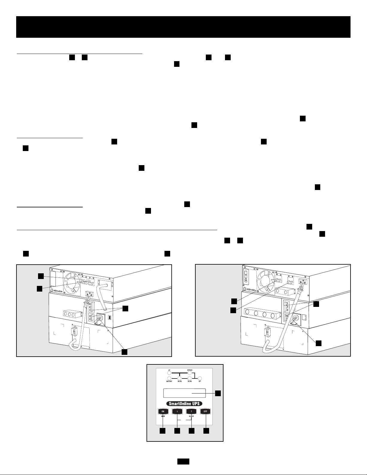
92
1. Сконфигурируйте ввод и вывод вашего ИБП: переведите ваш блок питания ИБП в статус настройки пут¸м одновременного
нажатия кнопок ( и ). Просмотрите опции настройки (используя èëè и выберите соответствующую настройку для
каждой из следующих опций, используя кнопку ВЫБОР
• Ввод и вывод напряжения: выберите 200, 208 или 240В переменного тока
• Частота вывода: Ваш ИБП выберет 50 или 60 Гц для того, чтобы соответствовать уровню ввода
• Режим экономии: ваш ИБП может работать в режиме онлайн с нулевым временем перехода. Он также может
работать в статусе сохранения энергии.
• Линейно-интерактивный режим: выберите Включить режим экономии для того, чтобы переключить ИБП в линейно-
интерактивный режим. Выберите Выключить режим экономии для того, чтобы переключить ИБП в онлайновый режим.
• После того, как вы выбрали эти опции, "покиньте" режим настройки при помощи кнопки выбора , потом покиньте
режим перемычки пут¸м нажатия кнопки ВКЛЮЧИТЬ , пока вы не услышите звуковой сигнал.
2. Включить ввод ИБП: Если блок питания ИБП подключен к модулю трансформатора, включите переключатели цепи
переменный ток к ИБП и Вывод . Включите переключатель цепи ввода блока питания Нажмите кнопку ВКЛЮЧИТЬ
блока питания ИБП, пока вы не услышите звуковой сигнал, означающий начало работы инвертера. Если ввод
электрического тока не проводит питание обычным образом, вы можете произвести "холодный старт" вашего ИБП от
батареи (ваша батарея должна быть заряжена хотя бы частично, для того чтобы операция была успешно проведена.
Нажмите и держите кнопку ВКЛЮЧИТЬ ,пока вы не услышите звуковой сигнал, означающий, что ваш ИБП начал
работать в режиме БАТАРЕЯ ВКЛЮЧЕНА. Обратите внимание на то, что некоторое электронное оборудование может
потребовать больше ампер во время старта; в случае старта от батареи, попробуйте уменьшить начальную нагрузку на ИБП.
Ваш ИБП произвед¸т краткий самостоятельный проверочный тест и покажет результаты на ЖК дисплее . Смотрите
"Самостоятельный проверочный тест старта" в разделе "Правила Пользования"
3. Включите вывод ИБП: Включите переключатель цепи вывод . Если ИБП подключен к модулю трансформатора, включите
переключатель Перевода на Работу Вручную из режима ПЕРЕМЫЧКА в НОРМАЛЬНЫЙ и включите переключатель
цепи выход. Ваш ИБП подаст питание к подсоедин¸нному оборудованию.
4. Для того, чтобы включить блок питания и модуль трансформатора ИБП: нажмите кнопку ВЫКЛЮЧИТЬ модуля блока
питания ИБП, пока не услышите звуковой сигнал. Произойд¸т загрузка. Инвертер отключ¸н. ЖК дисплей покажет
РЕЖИМ ПЕРЕМЫЧКИ. Выключите переключатели цепи ввода и вывода ( и ) модуля блока питания ИБП. Если ваш
ИБП подсоедин¸н к модулю трансформатора, выключите переключатели переменный ток к ИБП и переключатель вывода
. Загрузка произойд¸т и ЖК дисплей не загорится .
FD
GE
F
I
H
G
F
C
C
ED
C
A
B
BABA
ВКЛЮЧИТЬ/ВЫКЛЮЧИТЬ
Модели 6 КВА
Модели 10 КВА
D
E
G
H
E
G
H
Модели 6 КВА и 10 КВА
(Передняя панель)
D
F
C
A
B I
NORMAL
BY
PAS
S
N
O
R
M
A
L
B
Y
P
A
S
S
Page 93

93
Правила работы вручную
(для ремонта или замены модуля блока питания).
Следующая процедура имеет отношение только к конфигурациям ИБП, которые включают модуль трансформатора 6КВА или
10 КВА. Эта процедура подробно описывает как отремонтировать или заменить модуль блока питания, в то же время поставляя
питание к модулю трансформатора. Внимание: поскольку модули блока питания и батареи будут отключены бо время этой
процедуры, они не будут в состоянии поставлять поддержку батареи к оборудованию, подключенному к модулю
трансформатора в случае отключения электроэнергии.
ВНИМАНИЕ:Только для квалифицированного обслуживающего персонала. В случае неправильного выполнения этой
процедуры, ИБП может быть не отключен полностью, в результате чего возникает риск смертельного ис хода или травмы от
потенциального контакта с высоким напряжением.
1. Отключите программный продукт PowerAlert и отключите коммуникационный кабель от коммуникационных портов
модуля блока питания.
2. Поставьте переключатель перемычки модуля трансформатора в положение "ПЕРЕМЫЧКА".
3. Нажмите кнопку ВЫКЛЮЧИТЬ модуля блока питания и держите пока не услышите звуковой сигнал и сообщение
"РЕЖИМ ПЕРЕМЫЧКИ" не появится на ЖК дисплее
4. Выключите двухполюсный переключатель переменного тока модуля трансформатора на ИБП
5. Выключите двухполюсный переключатель ввода и двухполюсный переключатель вывода модуля трансформатора.
6. Отключите кабель модуля батареи от соединителя батареи блока питания.
7. ТОЛЬКО ДЛЯ 10КВА МОДУЛЕЙ БЛОКА ПИТАНИЯ: используйте измеритель напряжения для того, чтобы проверить
кабель, соединяющий блоки терминала модуля блока питания с блоком терминала модуля трансформатора, чтобы
убедиться в том, что блок питания обесточен. Удалите кабель после обесточивания блока питания.
Модуль блока питания теперь обесточен и можно производить ремонт/замену
JI
H
GF
E
D
C
B
A
Модели 6КВА (Задняя Панель)
Модели 10 КВА (Задняя Панель)
A
B
F
G
A
B
F
G
I
E
D
C
Модели 6КВА и 10 КВА
(Передняя Панель)
H
E
H
J
N
O
R
M
A
L
BY
PAS
S
N
O
R
M
A
L
B
Y
P
A
S
S
Page 94

94
РЕЖИМ ДИАГНОСТИКИ
ПЕРЕМЕННЫЙ
ТОК/ПОСТОЯННЫЙ ТОК OK
РЕЖИМ ДИАГНОСТИКИ
ТЕСТИРУЮЩИЙ ИНВЕРТЕР
ЗАГРУЗКА В ОНЛАЙНОВОМ
РЕЖИМЕ = XXX% X.XXKW
Правила Пользования
После того, как вы включили ИБП, он входит в Режим Диагностики и проводит краткий тест, продолжающийся примерно 15
секунд. Результаты проверочного теста показаны на ЖК дисплее в следующем порядке.
ЗАПУСК С ВВОДОМ
ПЕРЕМЕННОГО ТОКА
РРЕЖИМ ДИАГНОСТИКИ
ЧАСТОТА= ХХ ГЦ
РЕЖИМ ДИАГНОСТИКИ ВВОД
ПЕРЕМЕННОГО ТОКА OK
РЕЖИМ ДИАГНОСТИКИ
БАТАРЕЯ OK
РЕЖИМ ДИАГНОСТИКИ
ЗАРЯД OK
РЕЖИМ ДИАГНОСТИКИ
ПЕРЕМЕННЫЙ ТОК/ПОСТОЯННЫЙ
ÒÎÊ OK
РЕЖИМ ДИАГНОСТИКИ
ТЕСТИРУЮЩИЙ ИНВЕРТЕР
ЗАГРУЗКА В ОНЛАЙНОВОМ
РЕЖИМЕ= XXX% X.XXKW
РЕЖИМ ДИАГНОСТИКИ
ЧАСТОТА= ХХ ГЦ
РЕЖИМ ДИАГНОСТИКИ ВВОД
ПЕРЕМЕННОГО ТОКА РАВНОСТЬ
РЕЖИМ ДИАГНОСТИКИ
БАТАРЕЯ OK
РЕЖИМ ДИАГНОСТИКИ
ЗАРЯД OK
M
M
M
M
M
M
M
M
M
M
M
M
M
ЗАПУСК С ВВОДОМ
ПЕРЕМЕННОГО ТОКА
ХОЛОДНЫЙ
СТАРТ*
*Примечание: Если ИБП приводится в действие с холодного старта, СИД БАТАРЕЯ загорится.
Если во время проверочного теста замечена проблема, ЖК дисплей покажет сообщение об ошибке. Если ваш ИБП показывает
любое из следующих сообщений на ЖК дисплее, позвоните в техническую поддержку Трипп Лайт по номеру (773) 869-1234.
НЕИСПРАВНАЯ
БАТАРЕЯ!ПОЗВОНИТЕ ДЛЯ
ОБСЛУЖИВАНИЯ
ЗАРЯДКА НЕ
ПРОИЗОШЛА!ПОЗВОНИТЕ
ДЛЯ ОБСЛУЖИВАНИЯ
НЕТ ПОДАЧИ
ПЕРЕМЕННОГО/ПОСТОЯННОГ
О ТОКА!ПОЗВОНИТЕ ДЛЯ
ОБСЛУЖИВАНИЯ
НЕИСПРАВНЫЙ
ИНВЕРТЕР!ПОЗВОНИТЕ ДЛЯ
ОБСЛУЖИВАНИЯ
ОТСУТСТВИЕ ВЫВОДА!
ПОЗВОНИТЕ ДЛЯ
ОБСЛУЖИВАНИЯ
НЕИСПРАВНЫЙ
ВЕНТИЛЯТОР!ПОЗВОНИТЕ
ДЛЯ ОБСЛУЖИВАНИЯ
Самостоятельный Проверочный Тест Старта
Самостоятельный проверочный тест не пройден.
DIAGNOSTIC MODE
AC/DC OK
DIAGNOSTIC MODE
TESTING INVERTER
ON BATTERY MODE
LOAD = XXX% X.XXKW
DIAGNOSTIC MODE
FREQ OUT = XXHz
DIAGNOSTIC MODE
INPUT AC OK
DIAGNOSTIC MODE
INPUT AC OK
DIAGNOSTIC MODE
BATTERY OK
DIAGNOSTIC MODE
CHARGER OK
DIAGNOSTIC MODE
AC/DC OK
DIAGNOSTIC MODE
TESTING INVERTER
ONLINE MODE
LOAD = XXX% X.XXKW
DIAGNOSTIC MODE
FREQ OUT = XXHz
DIAGNOSTIC MODE
INPUT AC BAD
DIAGNOSTIC MODE
INPUT AC BAD
DIAGNOSTIC MODE
BATTERY OK
BAD BATTERY!
CALL FOR SERVICE
CHARGER FAILURE!
CALL FOR SERVICE
AC/DC FAILURE!
CALL FOR SERVICE
INVERTER FAILURE!
CALL FOR SERVICE
OUTPUT FAILURE!
CALL FOR SERVICE
FAN FAILURE!
CALL FOR SERVICE
Page 95
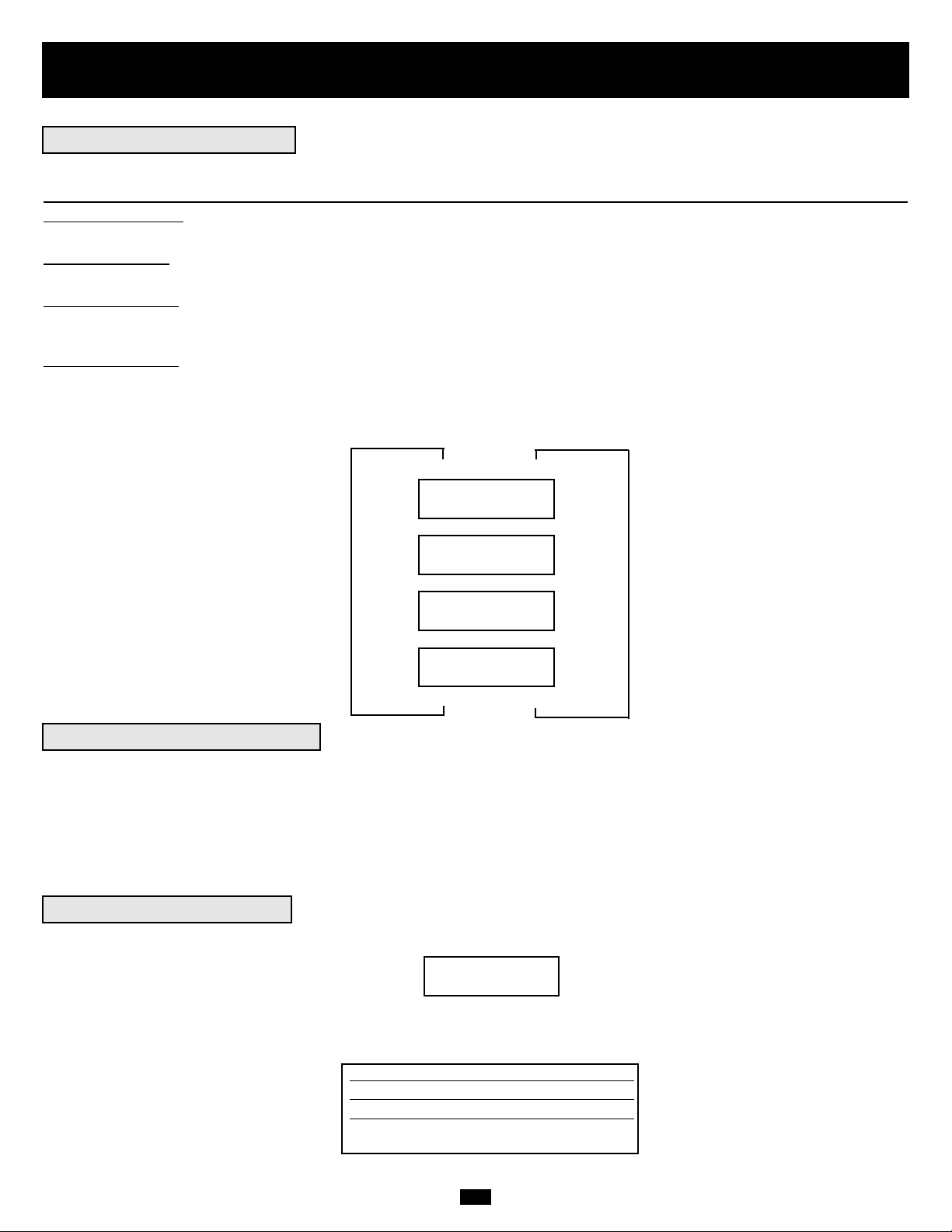
95
Правила Пользования, продолжение
Во время нормального использования ИБП, первая линия вашего ЖК дисплея показывает в каком операционном режиме
находится ваш ИБП: Онлайн, Экономии, От Батареи или Перемычки.
Онлайновый режим: ИБП обеспечивает питание переменного тока, в то время, когда электроэнергия пода¸тся и переключается
немедленно (с нулевым временем перехода) в режим От Батареи, если питание переменного тока прекращено.
Режим Экономии: ИБП обеспечивает питание переменного тока с высокой эффективностью, когда электроэнергия пода¸тся
и переключается быстро на режим от батареи, когда питание переменного тока прекращено..
Режим От Батареи: ИБП обеспечивает питание переменного тока от поддержки батареи, пока батарея может обеспечивать
питание. Он переключается назад в онлайновый режим или режим экономии, если электроэнергия пода¸тся и отключается,
если питание от батареи больше не пода¸тся.
Режим Перемычки:
ИБП пода¸т питание переменного тока, когда электроэнергия пода¸тся. ИБП отключается, когда подача
переменного тока прекращена.
Вторая линия ЖК дисплея показывает основные условия питания. Нажмите кнопки ВВЕРХ/ВНИЗ, чтобы просмотреть эти
базисные условия питания в последовательности, приведенной ниже.
ХХХХ РЕЖИМ ЗАГРУЗКИ=
XXX% X.XXÊÂÀ
ХХХХ РЕЖИМ ВВОД =
XXXV XX.X Ãö
ХХХХ РЕЖИМ ВЫВОД =
XXXV XX.X Ãö
ХХХХ РЕЖИМ БАТАРЕИ =
XXX В Постоянного Тока
M
M
M
Находясь в режиме от батареи, модуль блока питания ИБП подаст звуковой сигнал, указывающий на то, что он использует
питание батареи для поддержки подсоедин¸нного оборудования. Если подсоедин¸нные батареи заряжены более, чем
наполовину, прибор будет подавать звуковой сигнал два раза в секунду. Если подсоедин¸нные батареи заряжены менее, чем
наполовину, прибор будет подавать звуковой сигнал два раза в секунду. Если подсоедин¸нные батареи почти исчерпаны, блок
питания ИБП будет постоянно издавать звуковой сигнал.
Для того, чтобы отключить звуковой сигнал от батареи, нажмите кнопку "ВКЛЮЧИТЬ/ ОБЕЗЗВУЧИТЬ"
Когда ИБП обнаружит перегрузку вывода, ЖК дисплей переключится на следующее сообщение:
ИБП затем начн¸т отсч¸т. Если ИБП вс¸ ещ¸ перегружен в конце отсч¸та, ИБП автоматически перейд¸т в Режим Перемычки,
для того, чтобы предохранить инвертер. Продолжение отсч¸та варьируется в зависимости от уровня перегрузки следующим
образом:
ПЕРЕГРУЗКА! ЗАГРУЗКА =
XXX% X.XXÊÂÀ
Условия перегрузки Продолжение Отсч¸та
102% - 125% 1 минута
125% - 150% 30 секунд
>150% Немедленно
M
M
L
L
L
Нормальное Пользование
Звуковой Сигнал От Батареи
Сообщения о Перегрузке
XXXX MODE
LOAD = XXX% X.XXKW
XXXX MODE
IN = XXXV XX.X Hz
XXXX MODE
OUT = XXXV XX.X Hz
XXXX MODE
BATTERY = XXXVDC
OVERLOAD!
LOAD = XXX% X.XXKW
Page 96

96
Правила Пользования, продолжение
Находясь в режиме перемычки, ИБП, контролирует напряжение ввода и переводит питание ввода к подсоедин¸нному
оборудованию. ИБП не обеспечивает поддержку батарей в режиме Перемычки.
Если напряжение вывода отклоняется от приемлемого диапазона (между 15% выше и 20% ниже номинала), ИБП
демонстрирует состояние на сво¸м ЖК дисплее и прекращает подавать питание вывода. Если уровень питания возвращается
на приемлемый уровень, ИБП возобновляет подачу питания, и его ЖК дисплей показывает, что напряжение вывода было
слишком высоким или слишком низким, и вернулось к номиналу.
>15% выше номинала
>20% ниже номинала
Было слишком высоким,
сейчас номинально
Было слишком низким,
сейчас номинально
УСЛОВИЯ НАПРЯЖЕНИЯ
В РЕЖИМЕ ПЕРЕМЫЧКИ
СООБЩЕНИЯ ЖК
ДИСПЛЕЯ
Ваш ИБП отключится и ЖК покажет сообщение, если одно из следующих условий будет замечено. Внимание: во время всех
этих условий, СИД "Ввод", "Вывод" и "Перемычка" будут гореть.
Продолжительная
перегрузка
Вывод замыкания
öåïè
Команда удал¸нного
отключения (через DB9)
Команда удал¸нного
отключения (через EPO)
УСЛОВИЯ
ОТКЛЮЧЕНИЯ
СООБЩЕНИЯ НА
ЖК ДИСПЛЕЕ
Внутренние сбои
НЕТ ВЫВОДА ПЕРЕМЫЧКА
ПЕРЕМЕННОГО ТОКА
СЛИШКОМ ВЫСОКА
НЕТ ВЫВОДА ПЕРЕМЫЧКА
ПЕРЕМЕННОГО ТОКА
СЛИШКОМ НИЗКА
РЕЖИМ ПЕРЕМЫЧКИ
ПЕРЕМЕННЫЙ ТОК БЫЛ
СЛИШКОМ ВЫСОК
РЕЖИМ ПЕРЕМЫЧКИ
ПЕРЕМЕННЫЙ ТОК БЫЛ
СЛИШКОМ НИЗОК
ОТКЛЮЧИТЬ
ПЕРЕГРУЗКА XXX%
ОТКЛЮЧИТЬ
ЗАМЫКАНИЕ
ОТКЛЮЧИТЬ
УДАЛ¨ННАЯ КОМАНДА
ОТКЛЮЧИТЬ АВАРИЙНАЯ
ОСТАНОВКА!
ОТКЛЮЧИТЬ
+ПОСТОЯННЫЙ ТОК ВЫСОК
ОТКЛЮЧИТЬ
+ПОСТОЯННЫЙ ТОК НИЗОК
ОТКЛЮЧИТЬ -
ПОСТОЯННЫЙ ТОК ВЫСОК
ОТКЛЮЧИТЬ -
ПОСТОЯННЫЙ ТОК НИЗОК
ОТКЛЮЧИТЬ
ПЕРЕГРЕВ
Сообщение о Режиме Перемычки
Сообщения по отключению
NO OUTPUT
BYPASS AC TOO HI
NO OUTPUT
BYPASS AC TOO LO
BYPASS MODE
BYPASS AC WAS HI
BYPASS MODE
BYPASS AC WAS LO
SHUT DOWN
OVERLOAD XXX%
SHUT DOWN
O/P SHORT CIRCUIT
SHUT DOWN
REMOTE COMMAND
SHUT DOWN
EMERGENCY STOP!
SHUT DOWN
+ DC BUS HIGH
SHUT DOWN
+ DC BUS LOW
SHUT DOWN
- DC BUS HIGH
SHUT DOWN
- DC BUS LOW
SHUT DOWN
OVERTEMPERATURE
Page 97

97
Сервис/Гарантия
Ваш SmartOnline ИБП имеет ограниченную гарантию на 2 года, как описано ниже. Tripp LIte также предлагает различные
сервисные контракты, включая сервисные контракты на момент приобретения и 3х и 5ти летние SafeSure контракты на месте
расположения ИБП. Для получения дальнейшей информации, позвоните в службу поддержки клиентов Трипп Лайт по номеру
(773) 869-1234.
Tripp Lite гарантирует, что продукты Tripp Lite не имеют дефектов материалов или сборки. Гарантия распространяется на 2 года с момента покупки. Через 90 дней с момента покупки,
Tripp Lite обязуется, в соответствии с ограниченной гарантией, только заменить детали на продуктах с дефектами. Для того, чтобы получить обслуживание на гарантии, вы должны
позвонить в Tripp Lite или санкционированный центр обслуживания Tripp Lite. Продукты должны быть возвращены Tripp Lite или санкционированный центр обслуживания Tripp
Lite, транспортные расходы должны быть предоплачены, приложите краткое описание проблемы и подтверждение даты и места покупки. Эта гарантия не распространяется на
оборудование, которое было повреждено в случае неправильного или небрежного использования или несчастного случая, а также если прибор был измен¸н любым образом. Эта
гарантия покрывает только оригинального владельца, который должен зарегистрировать продукт должным образом в течение 10 дней с момента покупки.
Гарантия на любые предохранители для подавления напряжения от Tripp Lite анулируется, если они были подключены к выводу любой системы ИБП. Гарантия на любые ИБП
системы Tripp Lite анулируется, если предохранитель для подавления напряжения был подключен к панельке вывода.
ПОМИМО УКАЗАННОГО ВЫШЕ, TRIPP LITE НЕ ДА¨Т ГАРАНТИЙ, ПРЯМО ИЛИ КОСВЕННО, ВКЛЮЧАЯ ГАРАНТИИ ДЛЯ СООТВЕТСТВИЯ ОПРЕДЕЛ¨ННОЙ ЦЕЛИ
ПОКУПКИ. Некоторые штаты не позволяют ограничивать или исключать косвенные гарантии; следовательно, приведенные выше исключения, могут не относиться к покупателю.
КРОМЕ КАК УКАЗАНО ВЫШЕ, TRIPP LITE, НИ В КОЕМ СЛУЧАЕ НЕ ОТВЕТСТВЕНЕН ЗА ПРЯМЫЕ, КОСВЕННЫЕ, СПЕЦИАЛИЗИРОВАННЫЕ, СЛУЧАЙНЫЕ, ИЛИ
ЛОГИЧЕСКИ ВЫТЕКАЮЩИЕ ПОВРЕЖДЕНИЯ, ЯВЛЯЮЩИЕСЯ РЕЗУЛЬТАТОМ ИСПОЛЬЗОВАНИЯ ЭТОГО ПРОДУКТА, ДАЖЕ В СЛУЧАЕ, ЕСЛИ ВОЗМОЖНОСТЬ ТАКИХ
ПОВРЕЖДЕНИЙ БУДЕТ УКАЗАНА.
Более конкретно, TRIPP LITE не нес¸т ответственности за издержки, такие как: потерянная прибыль от годового дохода, потеря оборудования, потери от использования
оборудования, потери программного обеспечения, потери информации, стоимость замены, претензии третьих сторон, и.т.п.
Политика Tripp Lite состоит в постоянном совершенствовании. Спецификации могут быть изменены в любое время без предупреждения.
Сервис
Ограниченная 2х летняя гарантия
Page 98

98
Спецификации
Модели SU6000RT3U включают Модуль Блок Питания, Изолирующий Трансформаторный Модуль и Один Модуль Батареи. Модели
SU6000RT3UXR включают Модуль Блока Питания, Изолирующий Трансформационный Модуль и два Модуля Батареи.
Модель SU6000RT3U SU6000RT3UXR SU10KRT3U
Ввод
Диапазон Ввода Напряжения 156V~276V Однофазный 156V~276V Однофазный 156V~276V Однофазный
Модуль Ввода Напряжения 200/208/240Â 200/208/240Â 200/208/240 В
Ввод Частоты 50/60 Ãö ± 3 Ãö 50/60 Ãö ± 3 Ãö 50/60 Ãö ± 3 Ãö
Ââîä Òîêà 22.6 À 22.6 À 40 А
Проводимый Ток <150 À <150 À <200 А
Фактор Питания (Полная Нагрузка) >0.97 >0.97 >0.97
Эффективность (Полная Нагрузка/Онлайн) >87% >87% >88%
Переключатель Цепи Модуля
Блока Питания 40 А (2 полюса) 40 А (2 полюса) 63 А (2 полюса)
Переключатель Цепи Модуля
Трансформатора 40 А (2 полюса) 40 А (2 полюса) 63 А (2 полюса )
Вывод
ВА 6000 6000 10000
Ватт (Фактор Питания: 0.7) 4200 4200 7000
Форма Волны (Онлайн) Синусоида Синусоида Синусоида
Форма Волны (От Батареи) Синусоида Синусоида Синусоида
Напряжение Вывода (RMS) 100/120/200/208/240V 100/120/200/208/240V 100/120/200/208/240V
Частота Вывода 50/60 Hz (± 0.2 Гц От Батареи) 50/60 Hz (± 0.2 Гц От Батареи) 50/60 Hz (± 0.2 Гц От Батареи)
Регулирование Напряжения ±3% ±3% ±3%
Макс. Гармоничное Отклонение
(Линейная Полная Нагрузка) <3% <3% <3%
(Нелинейная Полная Нагрузка) <6% <6% <6%
Возможность Перегрузки 102% (продолжительность) 102% (продолжительность) 102% (продолжительность)
102%~125% (1 ìèí.) 102%~125% (1 ìèí.) 102%~125% (1 ìèí.)
125%~150% (30 ñåê.) 125%~150% (30 ñåê.) 125%~150% (30 ñåê.)
>150% (Немедленно) >150% (Немедленно) >150% (Немедленно)
Возможность Короткой Цепи 90A* 90A* 160A*
Переключатель Цепи Модуля Блока Питания 40A 6 3A 6 3A
Переключатель Цепи Модуля Трансформатора 30A (3 полюса) 63A (3 полюса) 63A (3 полюса)
Фактор Пика 3:1 3:1 3:1
* Возможность короткой цепи на низком уровне 2 Ватт 120 В для SU6000RT3U и SU6000RT3UXR более, чем 180 А, и
Использование
Время перехода онлайн (Линия к Батарее, Батарея к Линии )
0 ìñ 0 ìñ 0 мс
Различимый Шум (Полная Загрузка@1м) <50 dBA <55 dBA <55 dBA
Типичное Время Поддержки (с подсоедин¸нным модулем батареи)
(Полная Загрузка) 15 ìèí. + 37 ìèí. + 8 мин. +
(Загрузка Наполовину) 37 ìèí. + 79 ìèí. + 20 ìèí. +
Индикаторы
Включает ЖК Дисплей и СИД (ввод), БАТАРЕЯ, ПЕРЕМЕННЫЙ/ПОСТОЯННЫЙ ТОК, ПЕРЕМЫЧКА ПОСТОЯННЫЙ/ПЕРЕ МЕННЫЙ ТОК, (вывод).
Коммуникации
Включает RS-232 DB9 соединитель, сухой контакт DB9 соединитель и отверстие для аксессуаров.
Физические Спецификации
Размеры Прибора (В х Ш х Д)
Блок Питания 5.25 (3U) x 17.5 x 22.5 äì. 5.25 (3U) x 17.5 x 22.5 äì. 5.25 (3U) x 17.5 x 22.5 äì.
[13.4 x 44.5 x 57.2 cm.] [13.4 x 44.5 x 57.2 cm.] [13.4 x 44.5 x 57.2 cm.]
Модуль Трансформатора 5.25 (3U) x 17.5 x 26 äì. 5.25 (3U) x 17.5 x 26 äì. 5.25 (3U) x 17.5 x 26 äì.
[13.4 x 44.5 x 66.1 cm.] [13.4 x 44.5 x 66.1 cm.] [13.4 x 44.5 x 66.1 cm.]
Модуль Батареи #1 5.25 (3U) x 17.5 x 22.5 äì. 5.25 (3U) x 17.5 x 22.5 äì. 5.25 (3U) x 17.5 x 22.5 äì.
[13.4 x 44.5 x 57.2 cm.] [13.4 x 44.5 x 57.2 cm.] [13.4 x 44.5 x 57.2 cm.]
Модуль Батареи #2 (если существует) -/- 5.25 (3U) x 17.5 x 22.5 äì. -/-
[13.4 x 44.5 x 57.2 cm.]
Вес Отгрузки
Блок Питания 58 фунтов 58 фунтов 68 фунтов
[27 êã.] [27 êã.] [31 кг.]
Модуль Трансформатора 124 фунтов 124 фунтов 124 фунтов
[57 êã.] [57 êã.] [57 кг.]
Модуль Батареи #1 160 фунтов 160 фунтов 160 lфунтов
[73 êã.] [73 êã.] [73 кг.]
Модуль Батареи #2 (если существует) -/- 160 фунтов -/-
[73 êã.]
+Время поддержки может быть увеличено при помощи дополнительных Модулей Батареи
(модель:BP240V10RT-3U) прода¸тся отдельно.
Page 99

99
Спецификации, продолжение
Модели SU6000RT3UHV and SU10KRT3UHV включают Модуль Блока Питания и один Модуль Батареи.
Модели SU6000RT3UHV SU10KRT3UHV
Ввод
Диапазон Ввода Напряжения 156V~276V Однофазный 156V~276V Однофазный
Модуль Ввода Напряжения 200/208/240V 200/208/240V
Ввод Частоты 50/60 Ãö ± 3 Ãö 50/60 Ãö ± 3 Ãö
Ââîä Òîêà 22.6A 40A
Проводимый Ток <150A <200A
Фактор Питания (Полная Нагрузка) >0.97 >0.97
Эффективность (Полная Нагрузка/Онлайн) >87% >88%
Переключатель Цепи Модуля Блока Питания 40A (2 полюса) 63A (2 полюса)
Вывод
ВА 6000 10000
Ватт (Фактор Питания: 0.7) 4200 7000
Форма Волны (Онлайн) Синусоида Синусоида
Форма Волны (От Батареи) Синусоида Синусоида
Напряжение Вывода (RMS) 200/208/240V 200/208/240V
Частота Вывода 50/60 Hz 50/60 Hz
(± 0.2 Гц От Батареи) (± 0.2 Гц От Батареи)
Регулирование Напряжения ±3% ±3%
Макс. Гармоничное Отклонение
(Линейная Полная Нагрузка) <3% <3%
(Нелинейная Полная Нагрузка) <6% <6%
Возможность Перегрузки 102% (продолжительность) 102% (продолжительность)
102%~125% (1 ìèí.) 102%~125% (1 ìèí.)
125%~150% (30 ñåê.) 125%~150% (30 ñåê.)
>150% (Немедленно) >150% (Немедленно)
Возможность Короткой Цепи 90A 160A
Переключатель Цепи Модуля Блока Питания 40A 6 3A
Фактор Пика 3:1 3:1
Использование
Время перехода онлайн
(Линия к Батарее, Батарея к Линии) 0 ìñ 0 мс
Различимый Шум (Полная Загрузка@1м) <50 dBA <55 dBA
Типичное Время Поддержки (с подсоедин¸нным модулем батареи)
(Полная Загрузка) 15 ìèí.+ 8 мин. +
(Загрузка Наполовину) 37 ìèí.+ 20 ìèí. +
Индикаторы
Включает ЖК Дисплей и СИД (ввод), БАТАРЕЯ, ПЕРЕМЕННЫЙ/ПОСТОЯННЫЙ ТОК, ПЕРЕМЫЧКА ПОСТОЯННЫЙ/ПЕРЕМЕННЫЙ ТОК, (вывод).
Коммуникации
Включает RS-232 DB9 соединитель, сухой контакт DB9 соединитель и отверстие для аксессуаров.
Физические Спецификации
Размеры Прибора (В х Ш х Д)
Блок Питания 5.25 (3U) x 17.5 x 22.5 äì. 5.25 (3U) x 17.5 x 22.5 äì.
[13.4 x 44.5 x 57.2 cm.] [13.4 x 44.5 x 57.2 cm.]
Модуль Батареи 5.25 (3U) x 17.5 x 22.5 äì. 5.25 (3U) x 17.5 x 22.5 äì.
[13.4 x 44.5 x 57.2 cm.] [13.4 x 44.5 x 57.2 cm.]
Вес Отгрузки
Блок Питания 58 фунтов 68 фунтов
[27 êã.] [31 кг.]
Модуль Батареи 160 фунтов 160 фунтов
[73 êã.] [73 êã.]
+Время поддержки может быть увеличено при помощи дополнительных Модулей Батареи (модель:BP240V10RT-3U) прода¸тся отдельно.
Page 100

1111 W. 35th Street • Chicago, IL 60609 USA
Customer Support: (773) 869-1234 • Application Services: (773) 869-1236 • www.tripplite.com
200407104 93-2261
 Loading...