


1
Owner’s Manual
SmartOnline® S3MX
3-Phase UPS Systems
Models: S3M30KX, S3M40KX, S3M60KX, S3M80KX
Input: 220/230/240V (Ph-N), 380/400/415V (Ph-Ph), 3Ø 4-Wire + PE
1111 W. 35th Street, Chicago, IL 60609 USA • www.tripplite.com/support
Copyright © 2018 Tripp Lite. All rights reserved.

2
Table of Contents
1. Introduction 3
2. Important Safety Warnings 4
2.1 UPS Location Warnings 4
2.2 Equipment Connection Warnings 4
2.3 Battery Warnings 4
2.4 Transportation and Storage 5
2.5 Preparation 5
2.6 Installation 5
2.7 Connection Warnings 5
2.8 Operation 6
2.9 Standards 6
3. Installation and Setup 7
3.1 Unpacking and Inspection 7
3.2 Internal Battery Connection 9
3.3 Single UPS Installation 10
3.4 UPS Installation for Parallel Systems 12
3.5 External Battery Connection 13
4. Operation 14
4.1 Display Button Operation 14
4.2 LED Indicators and LCD Panel 14
4.3 Audible Alarm 16
4.4 Single UPS Operation 16
4.5 Parallel UPS Operation 18
4.6 LCD Panel Abbreviations 20
4.7 Setup Menu 20
4.8 Operating Mode/Status Description 26
4.9 Fault Codes 32
4.10 Warning Indicator 33
4.11 Warning Code 33
5. Communication 34
5.1 SNMP Monitoring Slot 34
5.2 EPO Connector 34
5.3 RS-232 Port 34
5.4 USB Port 34
6. Troubleshooting 35
7. Storage and Maintenance 36
7.1 Storage 36
7.2 Maintenance 36
7.3 Battery 36
7.4 Fan 36
8. Specifications 37
9. Warranty 40

3
1. Introduction
Tripp Lite’s SmartOnline S3MKX-Series Uninterruptible Power Supply (UPS) is a Voltage and Frequency Independent (VFI) true on-line,
double-conversion 3-phase UPS system. This UPS continuously conditions the incoming electrical power supply, eliminating power
disturbances that will otherwise damage sensitive electronic devices and minimizing system downtime from power fluctuations and
interruptions.
S3MKX-Series UPS systems are designed to the highest quality and performance standards and offer the following features:
•
Model Agency Number Capacity
S3M30KX AG-030 30kVA
S3M40KX AG-040 40kVA
S3M60KX AG-060 60kVA
S3M80KX AG-080 80kVA
• True on-line UPS – the highest level of UPS protection, fully regulates the incoming power with zero transfer time to battery in the event
of an extended mains failure so critical loads remain continuously supported
• Paralleling for capacity of up to three UPS systems
• High-efficiency performance in AC On-line and Battery Standby Modes minimise energy consumption
• Market-leading compact footprint, so more power can be provided from smaller spaces
• ECO Mode allows the UPS to operate on bypass in stable utility conditions and immediately transfers to inverter to support the load
when the utility input drops below tolerance
• High output power factor – more actual power allows more equipment to be supported
• Automatic and manual bypass increase system reliability and allow for maintenance without removing power from the attached load
• Wide input voltage window – the UPS system regulates even poor-quality incoming power without reverting to battery, maximising system
uptime and protecting battery life
• Matching external battery cabinets allow for increased battery autonomy
• Emergency shutdown via REPO
• SNMP Network Monitoring and Control and Contact-Closure Management cards available
SmartOnline S3MKX-Series UPS systems are ideally suited for protecting the following mission-critical electrical applications:
• IT infrastructure
• Telecommunications
• Networks (LAN/WAN)
• Corporate infrastructure
• Security and emergency systems
• Light industrial applications
• Financial institutions

4
2. Important Safety Warnings
SAVE THESE INSTRUCTIONS
This manual contains important instructions and warnings that should be followed during the installation and maintenance
of all Tripp Lite SmartOnline S3MX 3-Phase 30kVA, 40kVA, 60kVA and 80kVA UPS Systems and their batteries. Failure to
heed these warnings may affect your warranty.
2.1 UPS Location Warnings
• Install the UPS indoors, away from heat, direct sunlight, dust and excess moisture or other conductive contaminants.
• Install the UPS in a structurally sound area. The UPS is extremely heavy; take care when moving and lifting the unit.
• Only operate the UPS at indoor temperatures between 0° C and 40° C.
• Optimum UPS performance and maximum battery life is obtained when the operating temperature is maintained between
17° C and 25° C.
• Ensure the installation area has sufficient space for maintenance and ventilation of the UPS system. Maintain a minimum clearance of
50 cm from the rear, front and both sides of the UPS for maintenance and ventilation.
• Do not install the UPS near magnetic storage media, as this may result in data corruption.
2.2 Equipment Connection Warnings
• Use of this equipment in life support applications where failure of this equipment can reasonably be expected to cause the failure of the
life support equipment or to significantly affect its safety or effectiveness is not recommended.
• The UPS system contains its own energy source (battery). The output terminals may be live even when the UPS is not connected to an
AC supply.
2.3 Battery Warnings
This UPS contains LETHAL VOLTAGES. The UPS is designed to supply power, even when disconnected from utility power. Only
AUTHORISED SERVICE PERSONNEL should access the interior of the UPS after disconnecting utility and DC power.
Batteries present a risk of electrical shock and burns from high short-circuit current. Battery connection or replacement should be
performed only by qualified service personnel, observing proper precautions. Turn off the UPS before connecting or disconnecting
internal batteries. Use tools with insulated handles. Do not open the batteries. Do not short or bridge the battery terminals with any
object.
• The batteries are recyclable. Refer to local codes for disposal requirements or visit http://www.tripplite.com/support/recycling-program for
recycling information.
• Do not dispose of the batteries in a fire, mutilate the batteries or open the battery coverings. Escaping electrolytes may be toxic and
cause injury to skin and eyes.
• Do not disconnect the batteries while the UPS is in battery mode.
• Disconnect the charging source prior to connecting or disconnecting terminals.
• The following precautions should be observed:
1) Remove watches, rings and other metal objects.
2) Use tools with insulated handles.
3) Wear rubber gloves and boots.
4) Do not lay tools or metal parts on top of batteries or battery cabinets.
5) Determine whether the battery supply (+, -, N) is inadvertently grounded. If it is, remove the source of the ground. Contact with any
part of a grounded battery can result in electric shock. The likelihood of an electric shock is reduced if such grounds are removed
during installation and maintenance.
• Battery replacement should be performed only by authorised service personnel, using the same number and type of batteries (sealed
lead acid).
WARNING: In order to avoid any hazardous conditions during UPS installation and maintenance, these tasks may be
performed only by qualified and experienced electricians.
Please read this Owner’s Manual and the safety instructions carefully before installing or using the unit.

5
2.4 Transportation and Storage
To protect against shock and impact, transport the UPS system only in the original packaging.
The UPS must be stored in a room that is dry and ventilated.
2.5 Preparation
Condensation may occur if the UPS system is moved directly from a cold to a warm environment. The UPS system must be completely
dry before being installed. Please allow at least two hours for the UPS system to adjust to the environment.
Do not install the UPS system near water or in moist environments.
Do not install the UPS system in direct sunlight or near heat sources.
Do not block the ventilation holes on the UPS system’s housing.
2.6 Installation
Do not connect appliances or devices that could overload the UPS (i.e., equipment with large electrical motors) to the UPS output
sockets or terminal.
Carefully arrange cables so no one can step on or trip over them.
Do not block the UPS system’s air vents. The UPS must be installed in a location with good ventilation. Ensure adequate ventilation
space on each side of the unit.
The UPS contains an earthed terminal. In the final installed system configuration, ensure equipotential earth grounding to the external
UPS battery cabinet by connecting the earth terminals of both cabinets together.
The UPS should only be installed by qualified maintenance personnel.
An appropriate disconnect device such as short-circuit backup protection must be provided in the building wiring installation.
An integral single-emergency switching device should be included in the building wiring installation.
Connect the earth ground before connecting to the building wiring terminal.
Installation and wiring must be performed in accordance with local electrical codes and regulations.
2.7 Connection Warnings
• The UPS system does not contain standard backfeed protection inside. Isolate the UPS before working on this circuit. The isolation
device must be able to carry the UPS input current.
• This UPS should be connected with TN earthing system.
• The power supply for this unit must be 3-phase rated in accordance with the equipment nameplate. It also must be suitably grounded.
• The input power to 3-phase UPS models requires a 4-pole breaker.
• Use of this equipment in life support applications where failure of this equipment can reasonably be expected to cause the failure of the
life support equipment or to significantly affect its safety or effectiveness is not recommended.
• Connect the UPS power module’s grounding terminal to a grounding electrode conductor.
• The UPS is connected to a DC energy source (battery). The output terminals may still be live even when the UPS is not connected to an
AC supply.
2. Important Safety Warnings
Input
UPS
«Automatic backfeed protection
system» input, external to the UPS
(EN-IEC 62040-1)

6
2. Important Safety Warnings
• When installing the unit, verify that any maintenance bypass panel used is configured correctly before applying power to the unit.
• Be sure to place a warning label on all primary power isolators installed remotely from the UPS area and on any external access points
between such isolators and the UPS. The warning label shall carry the following wording or equivalent.
Before working on this circuit
- Isolate Uninterruptible Power System (UPS)
- Then check for Hazardous Voltage between all terminals
including the protective earth.
Risk of Voltage Backfeed
2.8 Operation
Do not disconnect the earth conductor cable on the UPS or the building wiring terminals at any time, as this will cancel the protective
earth of the UPS system.
In order to fully disconnect the UPS system, first press the “OFF” button, then disconnect the mains.
Ensure no liquid or other foreign objects can enter into the UPS system.
2.9 Standards
*Safety
IEC 62040-1: 2008+A1:2013
*EMI
Conducted Emission .....................................EN 62040-2: 2006 Category C3
Radiated Emission .......................................EN 62040-2: 2006 Category C3
*EMS
ESD............................................................EN 61000-4-2 Level 4
RS .............................................................EN 61000-4-3 Level 3
EFT. ............................................................EN 61000-4-4 Level 4
SURGE .......................................................EN 61000-4-5 Level 4
CS .............................................................EN 61000-4-6 Level 3
Power-Frequency Magnetic Field ....................EN 61000-4-8 Level 4
Low-Frequency Signals .................................EN 61000-2-2
Warning: This is a product for commercial and industrial applications in the second environment. Installation restrictions or
additional precautions may be needed to prevent disturbances.

7
3. Installation and Setup
3.1 Unpacking and Inspection
Unpack the unit and inspect the contents. Packaging may include additional accessories and components, depending on specific
customer orders.
• One (1) UPS
• One (1) Owner’s Manual
• One (1) RS-232 Cable
Other Accesory and Component Options Available
Cabling for UPS Paralleling:
• One (1) parallel cable (only available for parallel model) for every set of UPS units being paralled
• One (1) shared current cable (only available for parallel model) for every set of UPS units being paralled.
Additional Charging Board to increase the battery charger capacity:
• 4A charger boards may be paralled to increase the charger’s current capacity.
Note: Do not turn on the unit. Make sure to inspect the unit prior to installation. Ensure nothing inside the package was damaged during transportation.
Notify the carrier and dealer immediately if there is any damage or missing parts. Please keep the original packaging in a safe place for future use.
Rear Panel View - 30K and 40K Models
S3M30KX Rear Panel S3M40KX Rear Panel
S3M30KX and S3M40KX Input/Output Terminals
(See next page for number
descriptions.)

8
3. Installation and Setup
Front Panel View - 60K and 80K Models
S3M60KX Front View with Door Open S3M80KX Front View with Door Open S3M60KX and S3M80KX Input/Output Terminals
1
RS-232 Communications Port
2
USB Communications Port
3
Emergency Power Off (EPO) Connector
4
Share Current Port for Paralleling Units
5
Parallel Ports for Paralleling Units
6
SNMP Slot for Network Monitoring using (Optional WEBCARDLX)
7
External Battery Cabinet Connector
8
Line Input Circuit Breaker/Switch
9
Maintanance Bypass Switch (for Service Personnel Use Only)
10
Input/Output Terminal (Refer to 11 and 12 for Details)
11
Line Input Terminal
12
Output Terminal (Connects to Mission-critical Loads)
13
Input Grounding Terminal
14
Output Grounding Terminal
9
3. Installation and Setup
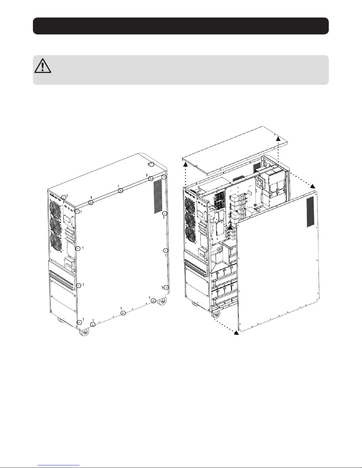
3.2 Internal Battery Connection
DANGER! LETHAL HIGH VOLTAGE HAZARD!
Potentially lethal high voltage exists within the batteries, even when not connected to a UPS system. Battery
connection should be performed by qualified service personnel only, following all the precautions listed in this manual
and adhering to local electrical codes.
Internal Battery Connection Procedure
1) Remove all screws labeled 1 (Figure 3.1).
2) Remove top plate, right side and left side plates (Figure 3.2).
See next page for steps 3-5.
Figure 3.1 Figure 3.2

10
3. Installation and Setup
3) For 30kA and 40kVA units with internal batteries, there are four battery cable points that are disconnected for shipping purposes
(refer to Figures 3.3 and 3.4). These four cables (two on the right side and two on the left side) will need to be reconnected for proper
battery cabinet operation.
Figure 3.3 Figure 3.4
4) Re-Install the top and side panels from Step 2.
5) Re-Install and tighten all screws from Step 1 with a torque of 1 N•m.
3.3 Single UPS Installation
Installation and wiring must be performed in accordance with local electrical codes/regulations and should only be performed by qualified
personnel.
1) Make sure the mains wire and breakers in the building can sustain the rated capacity of the UPS to avoid electric shock or fire hazard.
Note: Using a wall receptacle as the input power source for the UPS may result in the receptacle burning or being destroyed.
2) Switch off the mains switch in the building prior to installation.
3) Turn off all the connected devices before connecting to the UPS.
4) Prepare the power cables according to Table 3.1. Refer to Table 3.2 for UPS Input Breaker sizes and Table 3.3 for Battery Cabinet
Batteries and Breaker sizes.
WARNING:
• Before connecting any wires, make sure the AC input and battery power are completely shut off.
Table 3.1 Power Cables
Model
Wiring Specification
GroundInput (Ph) Output (Ph) Neutral Battery Packs
S3M30KX 8 AWG [8 mm2] 8 AWG [8 mm2] 4 AWG [21 mm2] N/A, when using only internal batteries 4 AWG [21 mm2]
S3M30KX 8 AWG [8 mm2] 8 AWG [8 mm2] 4 AWG [21 mm2]
4 AWG [21 mm2], for external battery pack
4 AWG [21 mm2]
S3M40KX 6 AWG [13 mm2] 6 AWG [13 mm2] 4 AWG [21 mm2] N/A, when using only internal batteries 4 AWG [21 mm2]
S3M40KX 6 AWG [13 mm2] 6 AWG [13 mm2] 4 AWG [21 mm2]
4 AWG [21 mm2], for external battery pack
4 AWG [21 mm2]
S3M60KX 4 AWG [21 mm2] 4 AWG [21 mm2] 1 AWG [42.4 mm2] 1 AWG [42.4 mm2] 4 AWG [21 mm2]
S3M80KX 2 AWG [34 mm2] 2 AWG [34 mm2] 1/0 AWG [54 mm2] 1/0 AWG [54 mm2] 2 AWG [34 mm2]
Table 3.2 UPS Input Breakers
Model (Agency Number) Breaker Size
S3M30KX (AG-030) 63A, 3-Pole
S3M40KX (AG-040) 80A, 3-Pole
S3M60KX (AG-060) 150A, 3-Pole
S3M80KX (AG-080) 6 x 30A Fuses/Phase
Battery cables that need to be reconnected
before proper operation of battery cabinet
Right Side
S3M30KX/S3M40KX
Left Side
S3M30KX/S3M40KX

11
3. Installation and Setup
Table 3.3 Battery Cabinet Batteries and Breakers
Model Batteries Included Battery Size and Qty. Breaker Size
BP480V100
Yes
100Ah x 40 400A, 3-Pole
BP480V65 65Ah x 40 300A, 3-Pole
BP480V40 40Ah x 40 200A, 3-Pole
BP480V100-NIB
No
(Designed For) 100Ah x 40 400A, 3-Pole
BP480V65-NIB (Designed For) 65Ah x 40 300A, 3-Pole
BP480V40-NIB (Designed For) 40Ah x 40 200A, 3-Pole
BP480V10
Yes
10Ah x 80 100A (Fuse)
BP480V09 9Ah x 80 100A (Fuse)
BP480V10-NIB No (Designed For) 10/9Ah x 80 100A (Fuse)
Notes:
• The S3M30KX cable should be able to withstand over 63A current. It is recommended to use 8 AWG (8 mm2) or thicker wire for Phase and 4 AWG
(21 mm2) or thicker wire for Neutral for safety and efficiency.
• The S3M40KX cable should be able to withstand over 80A current. It is recommended to use 6 AWG (13 mm2) or thicker wire for Phase and 4 AWG
(21 mm2) or thicker wire for Neutral for safety and efficiency.
• The S3M60KX cable should be able to withstand over 122A current. It is recommended to use 4 AWG (21 mm2) or thicker wire for Phase and 1 AWG
(42 mm2) or thicker wire for Neutral for safety and efficiency.
• The S3M80KX cable should be able to withstand over 160A current. It is recommended to use 2 AWG (34 mm2) or thicker wire for Phase and 1/0 AWG
(54 mm2) or thicker wire for Neutral for safety and efficiency.
5) Remove the terminal block cover to access the UPS system’s input, output and grounding connection terminals. Then connect the
wires according to the terminal block diagram shown below. Connect the grounding/earthing wires first when making other wire
connections.
Notes:
• Ensure the wires are tightly and securely connected to the terminals.
• Install the output breaker between the output terminal and the load. The breaker should be qualified with leakage current protective function.
• Cabling should be protected by flexible conduit and routed through the appropriate knockouts in the terminal block cover.
Terminal Block Wiring Diagram for S3M30KX and S3M40KX Terminal Block Wiring Diagram for S3M60K and S3M80K
PBAT
NBAT
TO UPS BAT
+
TO UPS BAT N
TO UPS BAT-
±240V Battery Connection Wiring
Note: Be sure to also add an equipotential bonding wire between the UPS and the External Battery Cabinets.
6) Re-attach the terminal block cover to the rear panel of the UPS.
Output OutputInput Input
BAT+ BAT-N B AT-
TO UPS BAT+
PBAT
NBAT
TO UPS BAT N
TO UPS BAT-

12
3. Installation and Setup
WARNING:
Make sure the UPS is not turned on prior to installation. The UPS should not be turned on until all wiring has been
completed and checked.
WARNING:
If an external battery pack is installed, switch off the battery breaker before installation.
WARNING:
Installation and wiring must be performed in accordance with the local codes/regulations and installed using the
following instructions by a qualified service technician only.
Note: Set the battery pack breaker in the “OFF” position, then install the battery pack.
• Pay close attention to the rated battery voltage posted on the rear panel. Connecting battery packs with the incorrect voltage may cause
permanent damage to the UPS.
• Pay close attention to the polarity markings on the external battery terminal block and make sure the correct battery polarity is
connected. Wrong connection may cause permanent damage to the UPS.
• Ensure the protective earth ground wiring is correct. The wire current spec, colour, position, connection and conductance reliability
should be carefully observed.
• Ensure the utility input and output wiring is correct. The wire current spec, colour, position, connection and conductance reliability
should be checked carefully. Make sure the R, S, T and N wiring is correct, not reversed and not short-circuited.
3.4 UPS Installation for Parallel Systems
If the UPS is only used for single operation, you may skip this section and proceed to section 3.7.
1) Parallel configuration supports up to three UPS systems. Do not attempt to link more than three UPS systems via parallel configuration.
2) Install and wire the UPS system according to section 3.5 guidelines.
3) When installing the parallel system, the length of input wires (R, S, T, N) in one UPS must be equal to the input wires of the other UPS.
Likewise, the length of output wires (R, S, T, N) must also be in equal length. If not, it will cause unbalance current on the output load.
4) Connect the input wiring of each UPS to an input breaker.
5) Connect the output wiring of each UPS to an output breaker.
6) Connect all output breakers to a main output breaker. This main output breaker will directly connect to the loads.
7) If an external battery pack is used, each UPS must be connected to an independent battery pack or a common battery pack.
Note: The parallel system cannot use a common external battery pack. Doing so will cause permanent damage to the entire system.
8) Refer to the following wiring diagram for parallel installation:
Wiring Diagram of Parallel System (S3M30KX and S3M40KX Models)
UPS 2
Output Input
UPS 1
 Loading...