

Page 1
WARRANTY
REGISTRATION
Register online today for
a chance to win a FREE Tripp Lite
product! www.tripplite.com/warranty
PowerVerter
Owner’s Manual
®
RV Series (v. 3.5)
DC-to-AC Inverter/Chargers
Input Output
Invert: 12 VDC 120V, 60 Hz. AC
Charge: 120V, 60 Hz. AC 12 VDC
Quiet Mobile Power
Congratulations! You've purchased the most advanced, feature-rich Inverter/Charger designed for recreational applications. Tripp Lite RV
Inverter/Chargers are the quiet alternative to generators-with no fumes, fuel or noise to deal with! You get AC electricity anywhere and anytime
you need it: away from shore power, rolling down the highway, dry camping in majestic back country or overnighting at a non-electric site. Your
Tripp Lite Inverter/Charger provides your appliances, equipment and electronics with utility- or generator-supplied AC electricity (filtered
through premium ISOBAR®surge protection) whenever available. In addition, it automatically powers your craft's 12V system and recharges
your connected battery bank-doing what traditional converter/chargers do. Whenever power blackouts, brownouts or high voltages occur, your
Inverter/Charger immediately and automatically switches over to inverting battery output to power connected AC equipment.
Better for Your Equipment Premium Protection Levels
• Built-In ISOBAR®Surge Protection
• Automatic Overload Protection
1111 W. 35th Street, Chicago, IL 60609 USA
Customer Support: (773) 869-1234
www.tripplite.com
Ideal Output for All Loads
• Frequency-Controlled Output
• Automatic Load Switching
• Balanced Load Sharing
Better for Your Batteries Faster Battery Recharge
• High-Amp, 3-Stage Battery Charger (adjustable)
Critical Battery Protection
• Battery Charge Conserver (Load Sense)
• Battery Temperature Sensing*
• High-Efficiency DC-to-AC Inversion
Better for You Quiet, Simple, Maintenance-Free Operation
• Multi-Function Lights & Switches
• Automatic Generator Starting*
• Moisture-Resistant Construction
†
Contents
Warranty/Warranty Registration 2
Safety 3
Mounting 10
Battery Connection 11
Feature Identification 4
Operation 5-6
Configuration 6-8
Battery Selection 9
* Available on all models except 750 models. †Inverter/Chargers are moisture-resistant, not waterproof.
Copyright © 2006. All rights reserved. PowerVerter
AC Input/Output Connection 12
Service/Maintenance 13
Troubleshooting 13
Français 14
®
is a registered trademark of Tripp Lite.
Page 2

Limited Warranty
Tripp Lite warrants its Inverter/Chargers to be free from defects in materials and workmanship for a 30 month period from the date of retail
purchase by end user.
Tripp Lite’s obligation under this warranty is limited to repairing or replacing (at its sole option) any such defective products. To obtain service
under this warranty you must obtain a Returned Material Authorization (RMA) number from Tripp Lite or an authorized Tripp Lite service center.
Products must be returned to Tripp Lite or an authorized Tripp Lite service center with transportation charges prepaid and must be
accompanied by a brief description of the problem encountered and proof of date and place of purchase. This warranty does not apply to
equipment which has been damaged by accident, negligence or misapplication or has been altered or modified in any way, including opening
of the unit’s casing for any reason. This warranty applies only to the original purchaser who must have properly registered the product
within 10 days of retail purchase.
EXCEPT AS PROVIDED HEREIN, TRIPP LITE MAKES NO WARRANTIES, EXPRESS OR IMPLIED, INCLUDING WARRANTIES OF
MERCHANTABILITY AND FITNESS FOR A PARTICULAR PURPOSE. Some states do not permit limitation or exclusion of implied
warranties; therefore, the aforesaid limitation(s) or exclusion(s) may not apply to the purchaser.
EXCEPT AS PROVIDED ABOVE, IN NO EVENT WILL TRIPP LITE BE LIABLE FOR DIRECT, INDIRECT, SPECIAL, INCIDENTAL OR
CONSEQUENTIAL DAMAGES ARISING OUT OF THE USE OF THIS PRODUCT, EVEN IF ADVISED OF THE POSSIBILITY OF SUCH
DAMAGE. Specifically, Tripp Lite is not liable for any costs, such as lost profits or revenue, loss of equipment, loss of use of equipment, loss
of software, loss of data, costs of substitutes, claims by third parties, or otherwise.
Regulatory Compliance Identification Numbers
For the purpose of regulatory compliance certifications and identification, your Tripp Lite product has been assigned a unique series num-
ber. The series number can be found on the product nameplate label, along with all required approval markings and information. When
requesting compliance information for this product, always refer to the series number. The series number should not be confused with the
marking name or model number of the product.
Tripp Lite has a policy of continuous improvement. Specifications are subject to change without notice.
WARRANTY REGISTRATION
Visit www.tripplite.com/warranty to register the warranty of your new Tripp Lite product.You'll be automatically entered into a drawing for a chance to win a
FREE Tripp Lite product!*
* No purchase necessary.Void where prohibited. Some restrictions apply. See website for details.
Note on Labeling Two symbols are used on the RV labels.
V~: AC Voltage V : DC Voltage
2R
Page 3
Important Safety Instructions
SAVE THESE INSTRUCTIONS!
This manual contains important instructions and warnings that should be followed during the installation, operation and storage of all Tripp Lite
Inverter/Chargers.
Note: For Marine installations, please replace this page with the page titled "For Marine Applications Only" found in the Owner's Manual Addendum.
Location Warnings
• Although your Inverter/Charger is moisture resistant, it is NOT waterproof. Flooding the unit with water will cause it to short circuit
and could cause personal injury due to electric shock. Never immerse the unit, and avoid any area where standing water might
accumulate. Mounting should be in the driest location available.
• Leave a minimum of 2" clearance at front and back of the Inverter/Charger for proper ventilation. To avoid automatic Inverter/Charger
shutdown due to overtemperature, any compartment that contains the Inverter/Charger must be properly ventilated with adequate
outside air flow. The heavier the load of connected equipment, the more heat will be generated by the unit.
• Do not install the Inverter/Charger directly near magnetic storage media, as this may result in data corruption.
• Do not install near flammable materials, fuel or chemicals.
Battery Connection Warnings
• The Inverter/Charger will not operate (with or without utility power) until batteries are connected.
• Multiple battery systems must be comprised of batteries of identical voltage, age, amp-hour capacity and type.
• Because explosive hydrogen gas can accumulate near batteries if they are not kept well ventilated, your batteries should not be
installed (whether for a mobile or stationary application) in a “dead air” compartment. Ideally, any compartment would have some
ventilation to outside air.
• Sparks may result during final battery connection. Always observe proper polarity as batteries are connected.
• Do not allow objects to contact the two DC input terminals. Do not short or bridge these terminals together. Serious personal injury
or property damage could result.
Equipment Connection Warnings
Do not use a Tripp Lite RV Inverter/Charger in life support or healthcare applications where a malfunction or failure of a
Tripp Lite RV Inverter/Charger could cause failure of, or significantly alter the performance of, a life support device or
medical equipment.
• You may experience uneven performance results if you connect a surge suppressor, line conditioner or UPS system to the output of
the Inverter/Charger.
• Tripp Lite recommends wiring the AC output to a GFCI protector (ground fault circuit interrupter).
• The main grounding lug should be connected to the vehicle chassis with an 8 AWG wire (minimum).
Operation Warnings
• Your Inverter/Charger does not require routine maintenance. Do not open the device for any reason. There are no user serviceable parts inside.
• Potentially lethal voltages exist within the Inverter/Charger as long as the battery supply and/or AC input are connected. During any
service work, the battery supply and AC input connection (if any) should therefore be disconnected.
• Do not connect or disconnect batteries while the Inverter/Charger is operating in either inverting or charging mode. Operating Mode
Switch should be in the OFF position. Dangerous arcing may result.
Caution: Some models have a failsafe AC pass-through feature where the AC output will be live (if AC input is available)
even though the operating mode switch is set to DC OFF.
3R
Page 4
Feature Identification
HOT IN
NEUTRAL IN
GROUND IN
GROUND OUT
HOT OUT
“FOR USE WITH COPPER WIRE ONLY”
NEUTRAL OUT
Identify the premium features on your specific model and quickly locate instructions on how to maximize their use.
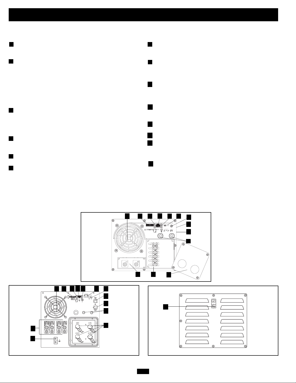
1
Configuration DIP Switches: optimize Inverter/Charger
operation depending on your application. See Configuration
section for setting instructions.
2
Operating Mode Switch: controls Inverter/Charger operation.
The “AUTO/REMOTE” setting ensures your equipment
receives constant, uninterrupted AC power. It also enables the
Inverter/Charger to be remotely monitored and controlled with
an optional remote module (Tripp Lite model APSRM4, sold
separately or included with select models). The “CHARGE
ONLY” setting allows your batteries to return to full charge faster
by turning the inverter off which halts battery discharging. See
Operation section for setting instructions.*
3
“LINE”, “INVERT”, “LOAD” LEDs: intuitive “traffic light”
signals show whether the Inverter/Charger is operating from AC
line power or DC battery power. It also warns you if the
connected equipment load is too high. See Operation section for
instructions on reading the indicator lights.
4
"BATT VOLTAGE" LEDs: these three lights will turn ON in
several sequences to show approximate battery level. See
Operation section for instructions on reading the indicator lights.
DC Power Terminals: connect to your battery terminals. See
5
Battery Connection section for instructions.
Hardwire AC Input/Output Terminals: securely connect the
6
Inverter/Charger to vehicle or facility electrical system input and
recommended GFCI protected output. See AC Input/Output
Connection section for instructions.
7
Resettable Circuit Breaker: protect your Inverter/Charger against
damage due to charger failure. See Operation section for
resetting instructions.
Remote Control Module Connector: allows remote monitoring
8
and control with an optional module (Tripp Lite model
APSRM4, sold separately or included with select models). See
remote module owner’s manual for connection instructions.
9
Battery Charge Conserver (Load Sense) Dial: conserves
battery power by setting the low-load level at which the
Inverter/Charger’s inverter automatically shuts off. See
Configuration section for setting instructions.
Main Ground Lug: properly grounds the Inverter/Charger to
10
vehicle grounding system or to earth ground. See Configuration
section for instructions.
Multi-Speed Cooling Fan: quiet, efficient fan prolongs equipment
11
service life.
12
Hardwire AC Input/Output Cover Plate
Battery Temperature Sensing Connector (not on 750 models):
13
prolongs battery life by adjusting charge based on battery temperature. Use with cable (included on select models). See
Configuration section for details.
14
Automatic Generator Start Connector (not on 750 models):
automatically cycles generator based on battery voltage. Use
with user-supplied cable. See Configuration section for details.
DC OFF - De-energizes unit and connects AC
Front View (Single Input/Output Hardwire Models)
8
3
4
1
11
5
10
Front View (Dual Input/Output Hardwire Models)
* OFF - De-energizes unit and AC output on most models.
to AC INon select models.
OUT
11
1
5
2
9
13
14
7
6
4R
8
6
Rear View (Single Input/Output Hardwire Models)
24 3
9
13
14
7
12
10
Side Mounted,
Not Shown
Side Mounted,
Not Shown
Page 5
Operation
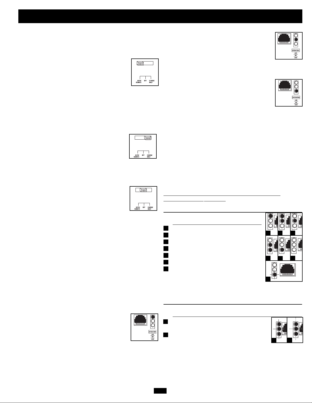
Switch Modes
After configuring, mounting and connecting your Inverter/Charger,
you are able to operate it by switching between the following operating modes as appropriate to your situation:
AUTO/REMOTE: Switch to this mode when you
need constant, uninterrupted AC power for connected
appliances and equipment. The Inverter/Charger will
continue to supply AC power to connected equipment
and to charge your connected batteries while utilityor generator-supplied AC power is present. Since the
inverter is ON (but in Standby) in this mode, it will automatically
switch to your battery system to supply AC power to connected
equipment in the absence of a utility/generator source or in
over/under voltage situations. “AUTO/REMOTE” also enables an
optional remote control module (Tripp Lite model APSRM4, sold
separately or included with select models) to function when connected to the unit.
CHARGE ONLY: Switch to this mode when you
are not using connected appliances and equipment in
order to conserve battery power by disabling the
inverter. The Inverter/Charger will continue to supply AC power to connected equipment and charge
connected batteries while utility- or generator-supplied AC power is
present. However, since the inverter is OFF in this mode, it WILL
NOT supply AC power to connected equipment in the absence of a
utility/generator source or in over/under voltage situations.
OFF (most models): Switch to this mode to shut
down the Inverter/Charger completely, preventing
the inverter from drawing power from the batteries,
and preventing utility AC from passing through to
connected equipment or charging the batteries. Use
this switch to automatically reset the unit if it shuts down due to
overload or overheating. First remove the excessive load or allow
the unit to sufficiently cool (applicable to your situation). Switch to
“OFF”, then back to “AUTO/REMOTE” or “CHARGE ONLY” as
desired. If unit fails to reset, remove more load or allow unit to cool
further and retry. Use an optional remote control module (Tripp Lite
model APSRM4, sold separately or included with select models) to
reset unit due to overload and overtemperature.
DC OFF (select models): De-energizes unit and connects AC
OUT
to AC IN.
Indicator Lights
Your Inverter/Charger (as well as an optional Tripp Lite Remote
Control Module, sold separately or included with select models) is
equipped with a simple, intuitive, user-friendly set of indicator
lights. These easily-remembered “traffic light” signals will allow
you, shortly after first use, to tell at a glance a wide variety of operating details.
“LINE Green LED”: If the operating mode switch
is set to “AUTO/REMOTE”, this light will ILLUMINATE CONTINUOUSLY when your connected
equipment is receiving continuous AC power supplied from a utility/generator source.
If the operating mode switch is set to “CHARGE ONLY”, this light
will BLINK to alert you that the unit’s inverter is OFF and will NOT
supply AC power in the absence of a utility/generator source or in
over/under voltage situations.
“INV” (Inverting) Yellow LED: This light will
ILLUMINATE CONTINUOUSLY whenever connected equipment is receiving battery-supplied,
inverted AC power (in the absence of a utility/generator source or in over/under voltage situations). This
light will be off when AC power is supplying the load. This light
will BLINK to alert you if the load is less than the Battery Charge
Conserver (Load Sense) setting.
“LOAD” Red LED: This red light will ILLUMINATE CONTINUOUSLY whenever the inverter is
functioning and the power demanded by connected
appliances and equipment exceeds 100% of load
capacity. The light will BLINK to alert you when the
inverter shuts down due to a severe overload or overheating. If this
happens, turn the operating mode switch “OFF”; remove the overload and let the unit cool. You may then turn the operating mode
switch to either “AUTO/REMOTE” or “CHARGE ONLY” after it
has adequately cooled. This light will be off when AC power is supplying the load.
“BATT VOLTAGE” LEDs: If the operating mode switch is in the
"AUTO/REMOTE" or "Charge Only" position, the LEDs indicate
the approximate charge level and voltage of your connected battery
bank and alert you to several fault conditions. See Chart for charge
and voltage levels.
LED Function with Switch in “AUT
O/REMOTE” or
“CHARGE ONLY” Position
Approximate Battery Charge Level*
LEDs Battery Capacity
Illuminated (Charging/Discharging)
Green 91%–Full
1
Green & Yellow 81%–90%
2
Yellow 61%–80%
3
Yellow & Red 41%–60%
4
5
Red 21%–40%
6
All three lights off 1%–20%
7
Flashing red 0% (Inverter
1
2 3
4
6
5
shutdown)**
* Charge levels listed are approximate. Actual conditions vary
depending on battery condition and load. ** Inverter shutdown protects battery against damage
due to excessive discharge.
7
Fault Condition
LEDs Fault
Illuminated Condition
All three lights Excessive discharge
1
flash slowly* (Inverter shutdown)
All three lights Overcharge (Charger
2
flash quickly** shutdown)
*Approximately ½ second on, ½ second off. See Troubleshooting section. Inverter shutdown
protects battery against damage due to excessive discharge.** Approximately ¼ second on, ¼
second off. Charger shutdown protects battery against damage due to overcharge. May also
indicate a battery charger fault exists. See Troubleshooting section.
1
2
5R
Page 6
INPUT C/B 10A
OUTPUT C/B 12A
B4 B3 B2 B1
A4 A3 A2 A1
Operation
(continued)
Resetting Your Inverter/Charger to Restore AC Power
Your Inverter/Charger may cease supplying AC power or DC charging power in order to protect itself from overload or to protect your electrical system. To restore normal functioning:
Overload Reset: Switch operating mode switch to “OFF” or “DC OFF” and remove some of the connected electrical load (ie: turn off some
of the AC devices drawing power which may have caused the overload of the unit). Wait one minute, then switch operating mode switch
back to either “AUTO/REMOTE” or “CHARGE ONLY.”
Configuration
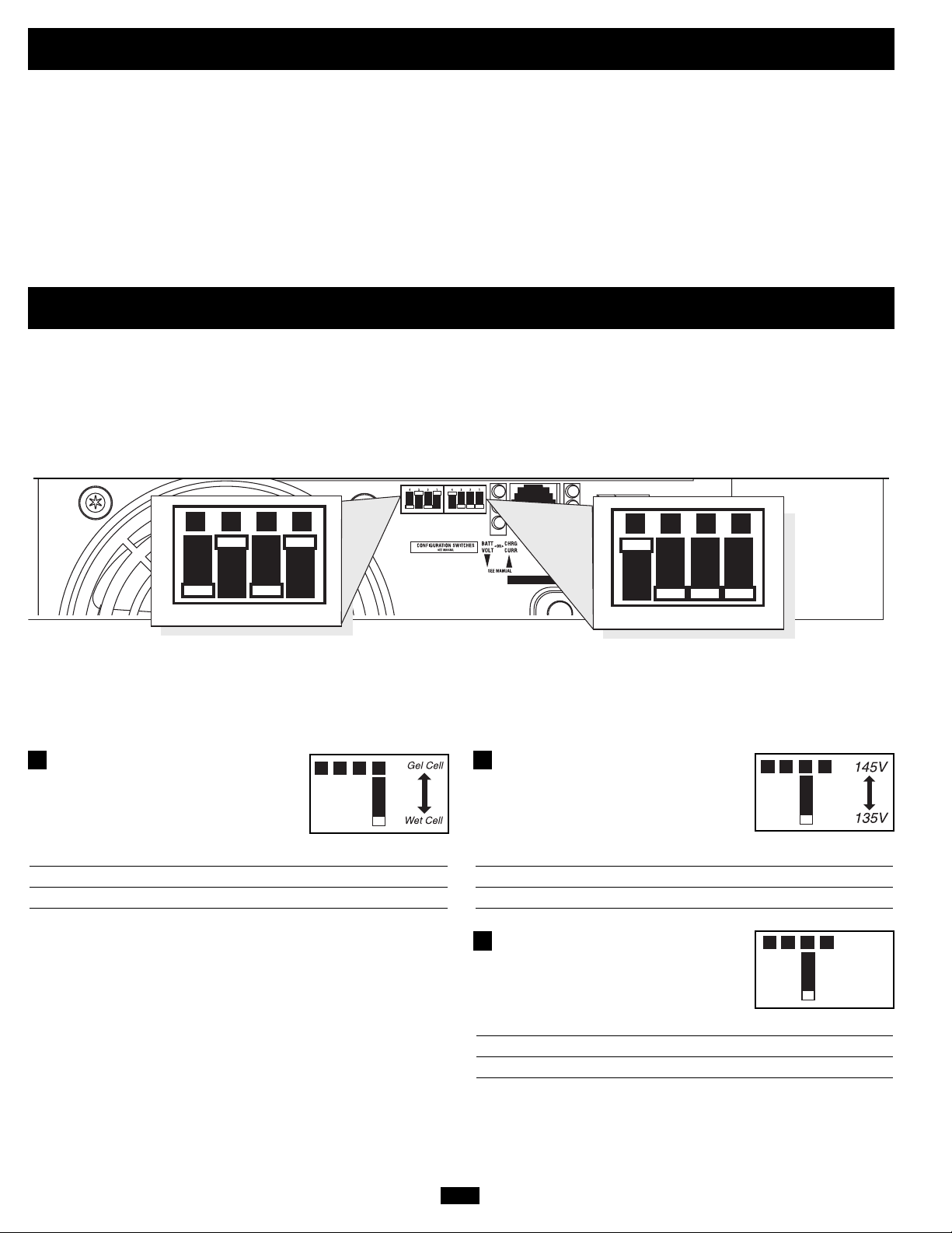
Set Configuration DIP Switches
Using a small tool, set the Configuration DIP Switches (located on the front panel, see diagram) to optimize Inverter/Charger operation
depending on your application. Refer to the appropriate section to review the instructions for your specific model.
Group B Dip Switches
Group A Dip Switches
Group A DIP Switches
Using a small tool, configure your Inverter/Charger by setting the four Group A DIP Switches (located on the front panel of your unit; see
diagram) as follows:
A1
Select Battery Type—REQUIRED
(All models)
CAUTION: The Battery Type DIP Switch setting must
match the type of batteries you connect, or your batteries
may be degraded or damaged over an extended period of
time. See “Battery Selection,” p. 9 for more information.
A1A2A3A4
Battery Type Switch Position
Gel Cell (Sealed) Battery Up
Wet Cell (Vented) Battery Down (factory setting)
A2
Select High AC Input Voltage Point
A1A2A3A4
for Switching to Battery—OPTIONAL*
(OEM models only)
Voltage Switch Position
145V Up
135V Down (factory setting)
A2
Charger Inhibit
A1A2A3A4
(Most models )
Function Switch Position
Charger Inhibited Up
Charger Enabled Down (factory setting)
* Most of your connected appliances and equipment will perform adequately when your Inverter/Charger’s High AC Input Voltage Point (DIP Switch #2 of Group A) is set to 135V and its Low AC Voltage Input Point (DIP Switches
#3 and #4 of Group A) are set to 95V. However, if the unit frequently switches to battery power due to momentary high/low line voltage swings that would have little effect on equipment operation, you may wish to adjust these settings. By increasing the High AC Voltage Point and/or decreasing the Low AC Voltage Point, you will reduce the number of times your unit switches to battery due to voltage swings.
6R
Page 7
Configuration
B1B2B3B4
B1B2B3B4
B1B2B3B4
B1B2B3B4
All Models
(continued)
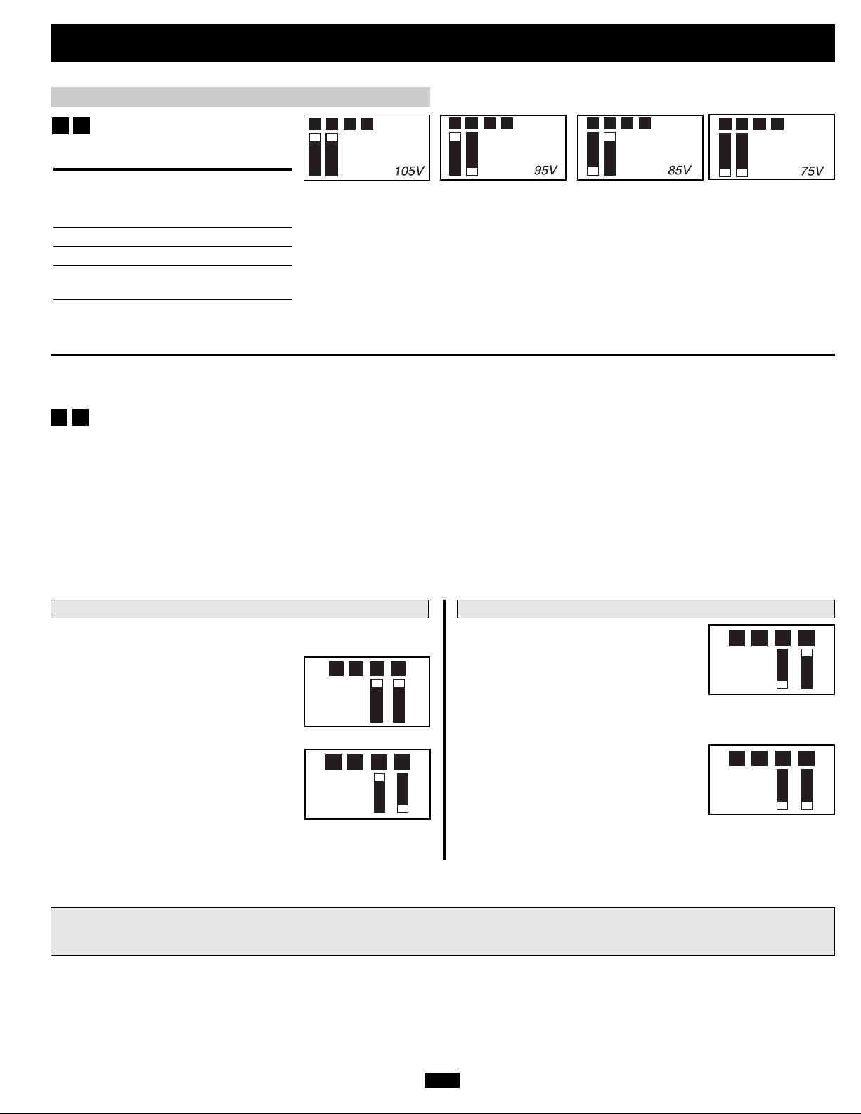
A4
A3
Select Low AC Input Voltage
A1A2A3A4
A1A2A3A4
A1A2A3A4
A1A2A3A4
Point for Switching to Battery—
OPTIONAL*
Switch
Voltage Position
105V #A4 Up & #A3 Up
95V #A4 Up & #A3 Down
85V #A4 Down & #A3 Up
75V #A4 Down & #A3 Down
(factory setting)
* Most of your connected appliances and equipment will perform adequately when your Inverter/Charger’s High AC Input Voltage Point (DIPSwitch #2 of Group A) is set to 135V and its Low AC Voltage Input Point (DIP Switches #3 and #4 of Group A are set to 95V. However,
if the unit frequently switches to battery power due to momentary high/low line voltage swings that would have little effect on equipment operation, you may wish to adjust these settings. By increasing the High AC Voltage Point and/or decreasing the Low AC Voltage Point, you
will reduce the number of times your unit switches to battery due to voltage swings.
Group B DIP Switches
B2
B1
Select AC Sharing—OPTIONAL
Your Inverter/Charger features a high-output battery charger that can draw a significant amount of AC power from your utility source or
generator when charging at its maximum rate. If your unit is supplying its full AC power rating to its connected heavy electrical loads at the
same time as this high charging occurs, the AC input circuit breaker could trip, resulting in the complete shut off of pass-through utility power.
To reduce the chance of tripping this breaker, all RV Inverter/Chargers may be set to automatically limit the charger output. This keeps the sum
of the unit’s AC load and charge power within the circuit breaker rating. This charger-limiting function has four settings, allowing you to
reduce the charger’s draw lower and lower, as needed, if the AC input circuit breaker keeps tripping under the normal AC loads of devices
you have connected downline from the unit. The figures show how to set your DIP Switches for charger-limiting.
All Models All Models, except RV2012UL & RV3012OEM
Select Battery Charger-Limiting Points—OPTIONAL
“Least Limiting” (#B2 Down & #B1 Up):
Charger-limiting begins when the
“Most Limiting” (#B2 & #B1 Up):
Charger-limiting takes effect the moment
any 120V AC load is applied; charger output falls gradually from full output at no
120V load passing through to no output at
full load.
“Less Limiting” (#B2 Up & #B1 Down):
Inverter/Charger’s load reaches 66% of the
Inverter/Charger’s load rating. Charger
output falls gradually from full output at
66% of the Inverter/Charger’s load rating to about 40% of full output at full load.
“No Limiting” (#B2 & #B1 Down): No
charger-limiting occurs at any load size.
Charger-limiting begins when the
Inverter/Charger’s load reaches 33% of the
Inverter/Charger’s load rating. Charger
output falls gradually from full output at
33% of the Inverter/Charger’s load rating to about 40% of full output
at full load.
Most models are factory preset to "Most Limiting". RV2012OEM is preset to "Less Limiting". RV2012UL and RV3012OEM models can only be set to "Most Limiting" or "Less Limiting" (B2
switch is non-functional).
7R
Page 8
e
Configuration
(continued)
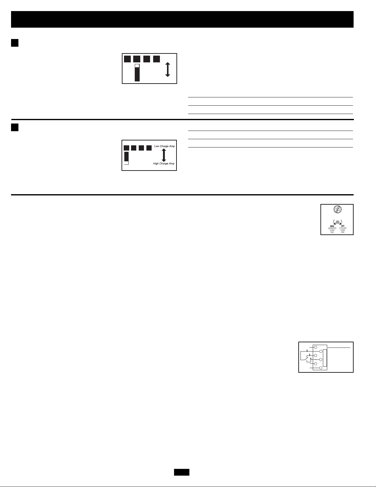
Select Equalize Battery Charge—OPTIONAL
B3
Setting Procedure
• Move to “Equalize” (DOWN) position for three seconds.
This DIP Switch is momentarily engaged
to begin the process of equalizing the
charge state of your battery’s cells by timelimited overcharge of all cells. This can
extend the useful life of certain types of
batteries; consult with your battery’s manufacturer to determine if
your batteries could benefit from this process. The charge equalization process is automatic; once started, it can only be stopped by
removing the input power.
Set Battery Charging Amps—OPTIONAL
B4
Check specifications for your unit’s high- and low-charging amp
options. By setting on high charging,
your batteries will charge at maximum
B1B2B3B4
Reset
• Move to “Reset” (UP) position and leave it there. This is the
factory default setting.
CAUTION: Do not leave DIP switch #B3 in the down position after beginning process. Battery
Equaliz
charge equalization should only be performed in strict accordance with the battery manufacturer’s
instructions and specifications.
Battery Charge Switch Position
Reset Up (factory setting)
Equalize Down—momentarily
Battery Charger Switch Position
Low Charge Amps Up
B1B2B3B4
High Charge Amps Down (factory setting)
speed and your RV 12V DC system
loads will be well-supplied. When setting on low charging, you lengthen the
CAUTION: When switching to the High Charge Amp setting, the user must ensure that the
amp hour capacity of their battery system exceeds the amperage of the High Charge Amp
setting or the batteries may be damaged or degraded.
life of your batteries (especially smaller ones).
Set Battery Charge Conserver (Load Sense) Dial—OPTIONAL
In order to save battery power, the unit’s inverter automatically shuts off in the absence of any power demand from connected
equipment or appliances (the electrical load). When the unit detects a load, it automatically turns its inverter function on.
Users may choose the minimum load the Inverter/Charger will detect by adjusting the Battery Charge Conserver Dial (see
diagram). Using a small tool, turn the dial clockwise to lower the minimum load that will be detected, causing the inverter to
turn on for smaller loads. When the dial is turned fully clockwise, the inverter will operate even when there is no load. Turn the
dial counterclockwise to increase the minimum load that will be detected, causing the inverter to stay off until the new minimum load is reached.
Note: the factory setting for the dial is fully clockwise. However, based on the threshold load to which you’d like the inverter to respond, you should adjust the dial counterclockwise to reduce its sensitivity until the inverter is active only when connected equipment or appliances are actually in use.
Connect Remote Control—OPTIONAL (All models)
All models feature an 8-conductor telephone style receptacle on the front panel for use with an optional remote control module (Tripp Lite model
APSRM4, sold separately or included with select models). The remote module allows the Inverter/Charger to be mounted in a compartment or cabinet out
of sight, while operated conveniently from within the living area or control panel of your RV. See instructions packed with the remote control module.
Connect Battery Temperature Sensing Cable—OPTIONAL (not on 750 models)
The battery temperature sensing function prolongs battery life by adjusting the charge float voltage level based on battery temperature. Connect
the sensor cable (the cable, included with select models, has an RJ style connector on one end and a black sensor on the other) to the RJ
style jack located on the side*of the Inverter/Charger labeled “Remote Temp. Sense.” With user-supplied electrical or duct tape, affix the sensor to the side of the battery below the electrolyte level. Make sure that nothing, not even tape, comes between the sensor and the side of the battery. To guard against false readings due to ambient temperature, place the sensor between batteries, if possible, or away from sources of
extreme heat or cold. If the sensor cable is not used, the Inverter/Charger will charge according to its default 25º C values.
Utilize Automatic Generator Starter Capability—OPTIONAL (not on 750 models)
All models except 750 models include an RJ type modular jack on the side*panel labeled “Generator Start”. Attach to vehicle generator ON/OFF switching mechanism with user-supplied cable (see Pin Configuration Diagram). Once
attached, the interface will allow the Inverter/Charger to automatically switch a vehicle generator on when connected battery voltage levels are low (11.6 VDC) and switch it off when battery voltage levels are high (14.1 VDC).
1
2
3
4
5
6
Pin Configuration
2 - Common
3 - N.C.
(Normally Closed)
4 - N.O.
(Normally Open)
* Or rear (1250 model).
8R
Page 9
Battery Selection
Select Auxiliary Battery Type (if any)
Select “Deep Cycle” batteries to receive optimum performance from your Inverter/Charger. Do not use ordinary car or starting batteries or batteries rated in
Cold Cranking Amps (CCA). If the batteries you connect to the Inverter/Charger are not true Deep Cycle batteries, their operational lifetimes may be significantly
shortened. If you are using the same battery bank to power the Inverter/Charger as well as DC loads, your battery bank will need to be appropriately
sized (larger loads will require a battery bank with a larger amp-hour capacity) or the operational lifetimes of the batteries may be significantly shortened.
Batteries of either Wet-Cell (vented) or Gel-Cell /Absorbed Glass Mat (sealed) construction are ideal. 6-volt “golf cart”, Marine Deep-Cycle or
8D Deep-Cycle batteries are also acceptable. You must set the Inverter/Charger’s Battery Type DIP Switch (see Configuration section for more
information) to match the type of batteries you connect or your batteries may be degraded or damaged over an extended period of time. In
many cases, the vehicle battery may be the only one installed. Auxiliary batteries must be identical to the vehicle batteries if they are connected to each other.
Match Battery Amp-Hour Capacity to Your Application
Select a battery or system of batteries that will provide your Inverter/Charger with proper DC voltage and an adequate amp-hour capacity
to power your application. Even though Tripp Lite Inverter/Chargers are highly-efficient at DC-to-AC inversion, their rated output capacities
are limited by the total amp-hour capacity of connected batteries and the support of your vehicle’s alternator if the engine is kept running.
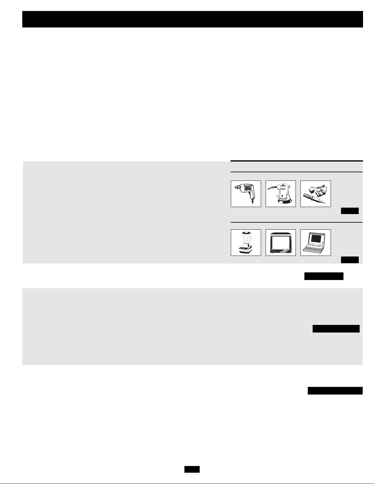
Example
• STEP 1: Determine Total Wattage Required
Add the wattage ratings of all equipment you will connect to your Inverter/Charger.
Wattage ratings are usually listed in equipment manuals or on nameplates. If your
equipment is rated in amps, multiply that number times AC utility voltage to determine
watts. (Example: a ¼ in. drill requires 2½ amps. 2½ amps × 120 volts = 300 watts .)
Note: Your Inverter/Charger will operate at higher efficiencies at about 75% - 80% of nameplate rating.
• STEP 2: Determine DC Battery Amps Required
Divide the total wattage required (from step 1, above) by the battery voltage (12)
to determine the DC amps required.
• STEP 3: Estimate Battery Amp-Hours Required (for operation unsupported
by the alternator)
Multiply the DC amps required (from step 2, above) by the number of hours you
estimate you will operate your equipment exclusively from battery power
before you have to recharge your batteries with utility- or generator-supplied
AC power. Compensate for inefficiency by multiplying this number by 1.2.
This will give you a rough estimate of how many amp-hours of battery power
(from one or several batteries) you should connect to your Inverter/Charger.
NOTE! Battery amp-hour ratings are usually given for a 20-hour discharge rate. Actual amp-hour capacities are less
when batteries are discharged at faster rates. For example, batteries discharged in 55 minutes provide only 50% of
their listed amp-hour ratings, while batteries discharged in 9 minutes provide as little as 30% of their amp-hour ratings.
Tools
¼" Drill
300W + 220W + 20W = 540W
Orbital Sander
Cordless Tool Charger
Appliances
Blender Color TV Laptop Computer
300W + 140W + 100W = 540W
540 watts ÷ 12V = 45 DC Amps
45 DC Amps × 5 Hrs. Runtime
× 1.2 Inefficiency Rating = 270 Amp-Hours
• STEP 4: Estimate Battery Recharge Required, Given Your Application
You must allow your batteries to recharge long enough to replace the charge
lost during inverter operation or else you will eventually run down your batteries.
To estimate the minimum amount of time you need to recharge your batteries
given your application, divide your required battery amp-hours (from step 3,
above) by your Inverter/Charger’s rated charging amps (see separate Specifications
Sheet).
NOTE! For Tripp Lite Inverter/Chargers providing 1000 watts or less of continuous AC power, a full-size battery
will normally allow sufficient power for many applications before recharging is necessary. For mobile applications,
if a single battery is continuously fed by an alternator at high idle or faster, then recharging from utility or generator
power may not be necessary. For Tripp Lite Inverter/Chargers over 1000 watts used in mobile applications, Tripp Lite
recommends you use at least two batteries, if possible fed by a heavy-duty alternator anytime the vehicle is running.
Tripp Lite Inverter/Chargers will provide adequate power for ordinary usage within limited times without the
assistance of utility or generator power. However, when operating extremely heavy electrical loads at their peak
in the absence of utility power, you may wish to “assist your batteries” by running an auxiliary generator or vehicle
engine, and doing so at faster than normal idling.
9R
270 Amp-Hours ÷ 55 Amps
Inverter/Charger Rating = 5 Hours Recharge
Page 10

Mounting
)
WARNING! Mount your Inverter/Charger BEFORE DC battery and AC power
connection. Failure to follow these instructions may lead to personal injury
and/or damage to the Inverter/Charger and connected systems.
Tripp Lite manufactures a variety of different Inverter/Chargers with a variety of different mounting options for use in vehicular or non-vehicular
applications. Tripp Lite recommends permanent mounting of your Inverter/Charger in any of the configurations illustrated below. User must
supply mounting hardware and is responsible for determining if the hardware and mounting surface are suitable to support the weight of the
Inverter/Charger. Contact Tripp Lite if you require further assistance in mounting your Inverter/Charger.
750 & 1250 Models Only
Whether mounted horizontally or vertically, the
Inverter must be located in an enclosed compartment,
shielded from outside weather conditions.
A
Using the measurements from the diagram, install two user-supplied ¼" (6 mm) fasteners into a rigid horizontal surface, leaving
the heads slightly raised. Slide the Inverter/Charger back over
the fasteners to engage the mounting slots molded on the bottom of
the Inverter/Charger cabinet. Install and tighten two user-supplied ¼" (6 mm) fasteners into the mounting feet molded on the
front of the Inverter/Charger cabinet.
The polycarbonate cabinet and mounting feet of your
Inverter/Charger are durable enough to allow for vertical mounting as well, if your vehicle compartment requires this configuration. For vertical mounting, the control panel of the
Inverter/Charger should face up.
B
C
Allow 2" minimum front and rear
clearance for adequate ventilation.
C
All Models Except 750 & 1250 Models
Note: When operating an RV2012UL marine model
in a marine application, refer to the accompanying
marine owners' manual addendum.
Whether mounted horizontally or vertically, the
Inverter must be located in an enclosed compartment,
shielded from outside weather conditions.
A
Using the measurements from the diagram, install two user-supplied ¼" (6 mm) fasteners into a rigid horizontal surface, leaving
the heads slightly raised. Slide the Inverter/Charger forward
over the fasteners to engage the mounting feet molded on the
front of the Inverter/Charger cabinet. Install and tighten
additional user-supplied ¼" (6 mm) fasteners into the mounting
feet molded on the rear and sides of the Inverter/Charger
cabinet*. The rear feet extend beyond the unit’s cabinet to
provide for adequate ventilation space behind the cooling fan(s);
they should not be removed.
The polycarbonate cabinet and mounting feet of your
Inverter/Charger are durable enough to allow for vertical mounting as well, if your vehicle compartment requires this configuration. For vertical mounting, the control panel of the
Inverter/Charger should face up.
B
6.75 in.
(17.1 cm)
7.87 in.
(20 cm)
Allow 2" minimum front and rear clearance for adequate ventilation.
A
4.5 in.
B
M
6.75 in.
(17.1 cm)
(11.4 cm)
5.57 in.
(14.16 cm.)
9.59 in.
1.64 in.
(4.15 cm.)
(24.35 cm.)
5.87 in.
(14.91 cm.)
5.87 in.
(14.91 cm.
B
9.59 in.
(24.35 cm.)
5.57 in.
A
Note: RV model cabinets may have different front panel features, but all mount as per the figure above.
(14.16 cm.)
M
* All models include front and rear mounting feet. Select
models include side mounting feet.
10R
Page 11

Battery Connection
Connect your Inverter/Charger to your batteries using the following procedures:
• Connect DC Wiring: Though your
Inverter/Charger is a
high-efficiency converter of electricity,
its rated output
capacity is limited by
the length and gauge
DC Connectors
of the cabling running from the battery to the unit. Use
the shortest length
and largest diameter
cabling (maximum
2/0 gauge) to fit
Dual DC Connectors (See
note at bottom of the page)
your Inverter/Charger’s DC Input terminals.
Shorter and heavier gauge cabling reduces
DC voltage drop and allows for maximum
transfer of current. Your Inverter/Charger is
capable of delivering peak wattage at up to
200% of its rated continuous wattage output
for brief periods of time. See Specifications
page for details. Heavier gauge cabling
should be used when continuously operating
heavy draw equipment under these conditions.
Tighten your Inverter/Charger and battery
terminals to approximately 3.5 Newtonmeters of torque to create an efficient connection and to prevent excessive heating at
this connection. Insufficient tightening of
the terminals could void your warranty. See
Specifications Sheet for Minimum
Recommended Cable Sizing Chart.
• Connect Ground: Using a #8 AWG wire
or larger directly connect the Main Ground
Lug to the vehicle’s chassis or earth ground.
See the Feature Identification section to locate
the Main Ground Lug on your specific
Inverter/Charger model. All installations
must comply with national and local codes
and ordinances.
• Connect Fuse: NEC (National Electrical
Code) article 551 requires that you connect
all of your Inverter/Charger’s positive DC
Terminals directly to a UL-listed fuse(s) and
fuse block(s) within 18 inches of the battery.
The fuse’s rating must equal or exceed the
Minimum DC Fuse Rating listed in your
Inverter/Charger’s specifications. See
Specifications for fuse and fuse block recommendations. See diagrams below for
proper fuse placement.
WARNING! • Failure to properly ground your Inverter/Charger to a vehicle’s chassis or earth
ground may result in a lethal electrical shock hazard.
• Never attempt to operate your Inverter/Charger by connecting it directly to output from an
alternator rather than a battery or battery bank.
• Observe proper polarity with all DC connections.
Vehicular
Your Inverter/Charger’s Nominal DC Input Voltage must match the voltage of your battery or batteries—12 Volts in most vehicular applications.
It is possible to connect your Inverter/Charger to the main battery within your vehicle’s electrical system. In most vehicles, the Inverter/Charger will be
connected to one or more dedicated auxiliary (house) batteries which are isolated from the drive system to prevent possible draining of the main battery.
3
12 Volts
2
12 Volts
5
4
6
2
1
2
12 Volts
12 Volts
11R
1
12 Volts
12 Volt Main Battery Connection
12 Volt Main and Auxiliary (House) Battery Connection (Isolated Parallel)
12 Volt Alternator Vehicle Battery Ground 12 Volt Main Battery 12 Volt Auxiliary (House) Battery UL-Listed Fuse & Fuse Block (mounted
within 18 inches of the battery) Battery Isolator Large Diameter Cabling, Maximum 2/0 Gauge to Fit Terminals 8 AWG (minimum) Ground Wire
NOTE: Select models include two positive and two negative DC terminals. Using the same connection architecture illustrated in the diagrams, run two 2/0 gauge cables from the Inverter/Charger’s
two negative terminals to the battery’s single negative terminal; run two 2/0 gauge cables from the Inverter/Charger’s two positive terminals, through two UL-listed fuses and fuse blocks, or equivalent,
(one on each cable), to the battery’s single positive terminal. Use the equivalent of two 2/0 cables in all other connections within the battery system. Connection to Two DC Terminals: It is acceptable
to use two cables to connect your battery to only one positive and one negative DC terminal, however, your Inverter/Charger will provide reduced output power. It doesn’t make a difference which
positive and negative terminal you choose for the connection because both positive terminals are internally bonded and both negative terminals are also internally bonded. In this connection you
must run one positive cable through one user-supplied UL-listed fuse and fuse block.
7
8
12 Volt Inverter/Charger
7
8
12 Volt Inverter/Charger
5
3
54321
876
Page 12

AC Input/Output Connection
To avoid overloading your Inverter/Charger, match the power requirements of the equipment you plan to run at any one time (add their total
watts) with the output wattage capacity of your Inverter/Charger model (see Specifications). Do not confuse “continuous” wattage with
“peak” wattage ratings. Most electric motors require extra power at start-up (“peak wattage”) than required to run continuously after startup, sometimes over 100% more. Some motors, such as in refrigerators and pumps, start and stop intermittently according to demand, requiring “peak wattage” at multiple, unpredictable times during operation. DoubleBoost™Feature: Tripp Lite Inverter/Chargers deliver up to twice
their nameplate rated wattage for up to 10 seconds,* providing the extra power needed to cold start heavy-duty tools and equipment.
OverPower™Feature: Tripp Lite Inverter/Chargers deliver up to 150% of their name-plate rated wattage for up to 1 hour,* providing plenty
of reserve power to reliably support tools and equipment longer.
* Actual duration depends on model, battery age, battery charge level and ambient temperature.
Warning! Consult a qualified electrician and follow all applicable electrical codes and requirements for
hardwire connection. Disconnect both DC input and AC utility supply before attempting hardwiring. Use wire
type THHN or equivalent with minimum temperature rating of 90°C.
Connection for Models with Hardwire Terminals
Output Connection Requirement: UL requires that the output terminals of all hardwire Inverter/Charger models must be connected to UL-listed GFCI receptacles
(required receptacle manufacturer/model series: Hubbell GF8300 or
Leviton 6598).
Single Input/Output Models
Input: Connect incoming wires to the hot (brown) , neutral (blue)
and ground* (green) terminals .
1
Output: Connect outgoing wires to the hot (black) , neutral (white)
and ground* (green) terminals .
Replace cover plate and tighten screws.* If the incoming conduit only contains two wires (hot and neutral), the incoming conduit must be bonded to the main ground lug on the unit. In any case,
the incoming conduit must be bonded to earth or vehicle ground, and the incoming conduit must be bonded to the outgoing conduit.
1
2
4
3
5
2
3
1
4
5
“FOR USE WITH COPPER WIRE ONLY”
HOT IN
NEUTRAL IN
GROUND IN
GROUND OUT
HOT OUT
NEUTRAL OUT
Note: Ground Bond Connection, Supplied
Dual Input/Output Models
Select models provide higher bypass power capacity by enabling connection of two separate
AC input sources. These two sources can be either two 120V legs split from a single 240V
service (with opposite phase on each 120V leg) or two different 120V sources. The
Inverter/Charger will only supply 120V output power and WILL NOT provide 240V output
even if it is connected to inputs from a split 240V service when in inverter mode. When the
Inverter/Charger is receiving AC power, it can supply connected loads with up to 30 amps
of power on each circuit**. When the Inverter/Charger is not receiving AC power, and has
switched to inverting DC battery power, it can supply connected loads with various amperage levels (see “Maximum Output AC Current” in Specifications section) on BOTH circuits.
Dual input/output models provide for either: a) dual-source inputs and outputs; b) singlesource input and output; or c) single-source input and dual-source outputs (with AC OUT
2 power only available in invert mode). Connect user-supplied wire and conduit to the con-
AC IN 1
AC IN 2
AC OUT 2
AC OUT 1
nections as follows:
Input: Connect incoming wires to hot (black for AC IN 1, black for AC IN 2), neutral
(white for AC IN 1, white for AC IN 2) and ground (green/yellow) wires.
Output: Connect outgoing wires to hot (black for AC OUT 1, black for AC OUT 2), neutral
(white for AC OUT 1, white for AC OUT 2) and ground (green/yellow) wires.
Dual-Source Input/Output*
• AC IN 1 will only provide line power to AC OUT 1.
• AC IN 2 will only provide line power to AC OUT 2.
• Inverted battery power is supplied to both AC OUT 1 and AC OUT 2.
Single-Source Input/Output*
• If you only have a single 120V AC input source, you must
connect it to AC IN 1.
• If you only have a single output circuit, you must connect it to
AC OUT 1
* Single-Source or Dual-Source Input/Output Connection: As well as supplying power to connected loads, AC IN 1 also provides power to the battery charger. If you connect a large load to AC OUT 1,
you should select a more limiting battery charger setting (see “Select Battery Charger-Limiting Points”) or you may experience continual nuisance tripping of the electrical service (source) circuit
breaker which supplies AC IN 1. The Inverter/Charger will only measure the current at AC OUT 1 to automatically limit the charger rate. AC IN 2 input current is passed through to AC OUT 2 without measurement. Single-Source Input/Dual-Source Output Connection: You may connect AC IN 1 and AC IN 2 to a single source to provide power to AC OUT 1 and AC OUT 2. However, the loads connected to
AC OUT 2 will not be measured for the purpose of automatic charger limitation. This could result in occasional tripping of the electrical service (source) circuit breaker. If this occurs, reduce the load on AC OUT
2 until nuisance tripping stops.
** Limited by user-supplied circuit breakers.
12R
Page 13

Service
Before returning your Inverter/Charger for service, follow these steps: 1.) Review the installation and operation instructions to ensure that
the service problem does not originate from a misreading of the instructions. Also, check that the circuit breaker(s) are not tripped.* 2.) If
the problem continues, do not contact or return the Inverter/Charger to the dealer. Instead, call Tripp Lite at (773) 869-1233. A service technician will ask for the Inverter/Charger’s model number, serial number and purchase date and will attempt to correct the problem over the
phone. 3.) If the problem requires service, the technician will issue you a Returned Material Authorization (RMA) number, which is
required for service. Securely pack the Inverter/Charger to avoid damage during shipping. Do not use Styrofoam beads for packaging.**
Any damages (direct, indirect, special, incidental or consequential) to the Inverter/Charger incurred during shipment to Tripp Lite or an
authorized Tripp Lite service center is not covered under warranty. Inverter/Chargers shipped to Tripp Lite or an authorized Tripp Lite service center must have transportation charges prepaid. Mark the RMA number on the outside of the package. If the Inverter/Charger is within the warranty period, enclose a copy of your sales receipt. Return the Inverter/Charger for service using an insured carrier to the address
given to you by the Tripp Lite service technician.
* This is a common cause of service inquiries which can be easily remedied by following the resetting instructions in this manual. ** If you require packaging, the technician can arrange to send you proper packaging.
Maintenance
Your Inverter/Charger requires no maintenance and contains no user-serviceable or replaceable parts, but should be kept dry at all times.
Periodically check, clean and tighten all cable connections, as necessary, both at the unit and at the battery.
Troubleshooting
Try these remedies for common Inverter/Charger problems before calling for assistance. Call Tripp Lite Customer Service at (773) 869-1234
before returning your unit for service.
SYMPTOM PROBLEMS CORRECTIONS
No AC Output Unit is not properly connected to utility power Connect unit to utility power.
(All Indicator Lights are OFF) Operating Mode Switch is set to “OFF” and AC input Set Operating Mode Switch to “AUTO/REMOTE” or “CHARGE ONLY”.
Battery Not Recharging Connected batteries are dead. Check and replace old batteries.
(AC Input Present) Battery fuse* is blown. Check and replace fuse.*
All Three “BATT VOLT/CHRG CURR” Battery is excessively discharged. Unit will shut down to Use an auxiliary charger* to raise battery voltage. Check external
LEDs are slowly flashing (½ second prevent battery damage. battery connections and fuse. Unit automatically resets when
flashes) with Operating Mode Switch in condition is cleared.
the “AUTO/REMOTE” position.
All Three “BATT VOLT/CHRG CURR” Battery is overcharged. Unit will shut down to prevent Disconnect any auxiliary chargers. Reset by moving Operating Mode
LEDs are rapidly flashing (¼ second battery damage. The problem may be with connected auxiliary Switch to “OFF”. Wait 1 minute and switch to “AUTO/REMOTE.”
flashes) with Operating Mode Switch in chargers, if any, or with the unit’s charger. If unit remains in shutdown mode after several attempts to reset,
the “AUTO/REMOTE” position. contact Tripp Lite Customer Service for assistance.
Red “LOW” Battery Indicator Light is Battery voltage is low. Unit has shut down If AC power (utility- or generator-supplied) is present, the unit will
flashing with Operating Mode Switch in the to protect battery from damage. automatically reset itself and start recharging connected batteries.
”AUTO/REMOTE” position. However, if an external charger is used to recharge the batteries,
Red “LOAD” Operation Inverter is overloaded. Unit will automatically shut down Reduce load. Reset by moving Operating Mode Switch to “OFF”.
Indicator Light flashing after 5 seconds. Wait 1 minute. Switch to “AUTO/REMOTE” or “CHARGE ONLY”.
* User-supplied.
is present.
This is normal when the Operating Mode Switch is set to No correction is required. AC output will return when AC input
“CHARGE ONLY” and AC input is absent. returns. Set Operating Mode Switch to “AUTO/REMOTE” if you
Circuit breaker is tripped. Reset circuit breaker.
Unit has shut down due to battery overcharge (preventing Disconnect any auxiliary chargers. Reset by moving Operating Mode
battery damage). The problem may be with connected Switch to “OFF”.Wait 1 minute and switch to “AUTO/REMOTE” or
auxiliary chargers, if any, or with the unit’s charger. “CHARGE ONLY.” If unit remains in shutdown mode after several
Unit has shut down due to excessive battery discharge. Use an auxiliary charger* to raise battery voltage. Check external
Unit has shut down due to overload. Reduce load. Reset by moving Operating Mode Switch to “OFF”.
Battery cabling* is loose. Check and tighten or replace cabling.*
Unit has shut down due to battery overcharge (preventing Disconnect any auxiliary chargers. Reset by moving Operating Mode
battery damage). The problem may be with connected Switch to “OFF”.Wait 1 minute and switch to “AUTO/REMOTE” or
auxiliary chargers, if any, or with the unit’s charger. or “CHARGE ONLY.” If unit remains in shutdown mode after several
Input circuit breaker is tripped. Reset circuit breaker.
False reading due to undersized or Use sufficient size DC cable sufficiently connected to
insufficiently connected DC cabling. Inverter/Charger.
13R
require AC output.
attempts to reset, contact Tripp Lite Customer Service for assistance.
battery connections and fuse. Unit automatically resets when
condition is cleared.
Wait 1 minute. Switch to “AUTO/REMOTE” or “CHARGE ONLY”.
attempts to reset, contact Tripp Lite Customer Service for assistance.
you will need to manually reset the unit by moving the Operating
Mode Switch to “OFF” for two seconds then returning it to
“AUTO/REMOTE”.
Page 14

Manuel du propriétaire
PowerVerter
®
Série RV (v. 3.5)
Chargeurs/Onduleurs CC vers CA
Entrée Sortie
Inversion : 12 V CC 120V, 60 Hz. CA
Charge : 120V, 60 Hz. CA 12 V CC
Alimentation mobile silencieuse
Félicitations ! Vous avez acheté le circuit inverseur/chargeur le plus avancé riche en options conçu pour les applications récréationnelles.
Le circuit inverseur/chargeur RV de Tripp Lite est l'alternative silencieuse aux générateurs - sans avoir affaire à la fumée, au carburant ou
au bruit. Vous obtenez une alimentation électrique c.a. en tout temps et partout où vous en avez besoin : loin de l'alimentation externe, en
roulant sur l'autoroute, en camping au fond des bois ou durant la nuit sur un site sans électricité. Votre circuit inverseur/chargeur alimente
vos électroménagers, vos équipements et appareils électroniques d'une alimentation c.a. de service - ou provenant d'une génératrice - (filtré à travers la protection de surtension ISOBAR®) lorsque disponible. De plus, il alimente automatiquement votre système de véhicule 12V
et recharge votre banque de piles connectées - effectuant ce qu'un convertisseur/chargeur fait. Lors des pannes de courant ou s'il se produit
des affaissements ou des hausses de la tension, votre circuit inverseur/chargeur commute automatiquement et immédiatement pour invertir
la sortie de la pile à l'équipement c.a. connecté.
Meilleur pour votre équipement Niveaux de protection de qualité supérieure
• Protection ISOBAR®intégrée contre les surtensions
• Protection automatique de surcharge
1111 W. 35th Street, Chicago, IL 60609 USA
Support à la clientèle: (773) 869-1234
www.tripplite.com
Sortie idéale pour toutes les charges
• Sortie à fréquence contrôlée
• Commutation automatique de charge
• Partage équilibré des charges
Meilleur pour votre batterie Recharge plus rapide de batterie
• Ampérage élevé, Chargeur de batterie à 3 étages (réglable)
Protection efficace de la batterie
• Conservateur de charge de batterie (Détecteur de charge)
• Détection de température de batterie*
• Inversion hautement efficace de CC à CA
Meilleur pour vous Fonctionnement silencieux, simple et sans entretien
• Lumières et commutateurs multi-fonctions
• Démarrage automatique de la génératrice*
• Fabrication résistant à l'humidité
†
Table des matières
Garantie 15
Sécurité 16
Montage 23
Connexion de la batterie 24
Identification des caractéristiques 17
Fonctionnement 18-19
Configuration 19-21
Choix de batterie 22
* Disponible sur tous les modèles sauf les modèles 750. †Les chargeurs-onduleurs résistent à l'humidité mais ne sont pas étanches.
Copyright © 2006. Tous droits réservés. PowerVerter® marque enregistrée de Tripp Lite.
Connexion d'entrée/sortie CA 25-26
Service/Entretien 26
Dépannage 27
English 1
Page 15

Garantie limitée
Tripp Lite garantit que ses chargeurs-onduleurs sont exempts de défauts de matériel et de fabrication pendant une période de 30 mois à partir de
la date d'achat au détail par l'utilisateur.
Dans le cadre de cette garantie, l'obligation de Tripp Lite est limitée à la réparation ou au remplacement (à son choix) des produits défectueux.
Pour bénéficier d'un service dans le cadre de cette garantie, vous devez obtenir un numéro d'autorisation de retour de matériel (RMA) de Tripp
Lite ou d'un centre de service autorisé par Tripp Lite. Les produits doivent être renvoyés à Tripp Lite ou à un centre de service autorisé par Tripp
Lite avec les frais de port prépayés et doivent être accompagnés d'une brève description du problème et de la preuve de la date et du lieu de
l'achat. Cette garantie ne s'applique à l'équipement endommagé par accident, négligence ou mauvais usage ou qui a été modifié d'une quelconque façon, y compris l'ouverture du boîtier de l'unité quelque soit la raison. Seul l'acheteur initial qui a enregistré correctement le produit dans
les dix jours de l'achat peut bénéficier de cette garantie.
À L'EXCEPTION DE CE QUI EST CONTENU DANS LA PRÉSENTE, TRIPP LITE N'OFFRE AUCUNE GARANTIE EXPRESSE OU IMPLICITE,
Y COMPRIS LES GARANTIES DE QUALITÉ MARCHANDE OU DE CONFORMITÉ À UN BESOIN PARTICULIER. Certains états ne permettent
pas la limitation ou l'exclusion de garanties implicites, en conséquence les limitations ou exclusions ci-dessus pourraient ne pas s'appliquer à l'acheteur.
À L'EXCEPTION DE CE QUI EST CONTENU CI-DESSUS, EN AUCUN CAS TRIPP LITE NE SERA TENU RESPONSABLES DE DOMMAGES
DIRECTS, INDIRECTS, SPÉCIAUX, ACCESSOIRES OU CONSÉCUTIFS ISSUS DE L'USAGE DE CE PRODUIT, MÊME EN CAS D'AVIS DE
LA POSSIBILITÉ D'UN TEL DOMMAGE. En particulier, Tripp Lite n'est pas responsable des coûts, tels que les pertes de profits ou de recettes,
la perte d'équipement, la perte de l'usage d'équipement, la perte de logiciels, la perte de données, les coûts de remplacement, les réclamations
par des tiers ou autre.
Numéros d'identification de conformité aux règlements
À des fins de certification et d'identification de conformité aux règlements, votre produit Tripp Lite a reçu un numéro de série unique. Ce numéro
se retrouve sur la plaque signalétique du produit, avec les inscriptions et informations d'approbation requises. Lors d'une demande d'information
de conformité pour ce produit, utilisez toujours le numéro de série. Il ne doit pas être confondu avec le nom de la marque ou le numéro de modèle du produit.
Tripp Lite a une politique d'amélioration continue. Les spécifications sont sujettes à changement sans préavis.
Remarque sur l'étiquetage Deux symboles sont utilisés sur les étiquettes de VR.
V~: voltage CA V : voltage CC
15R
Page 16

Importantes directives de sécurité
CONSERVEZ CES DIRECTIVES!
Ce manuel contient d'importantes directives et mises en garde que vous devez suivre pendant l'installation, le fonctionnement et l'entreposage
de tous les chargeurs-onduluers de Tripp-Lite.
Remarque : pour les installations marines, remplacez cette page par la page titrée "Pour les applications marines seulement" que vous retrouverez dans l'annexe du manuel du propriétaire.
Mises en garde concernant l'emplacement
• Même si votre chargeur-onduleur résiste à l'humidité, il N'est PAS étanche.. Noyer l'unité entraînerait un court-circuit et pourrait
causer des blessures par choc électrique. Ne jamais immerger l'unité et éviter toute zone où de l'eau pourrait s'accumuler. Il faut la
fixer dans la zone la plus sèche possible.
• Laisser un dégagement d'au moins 51mm (2 po) à l'avant et à l'arrière du chargeur-onduleur pour une bonne aération. Pour éviter la
fermeture automatique du chargeur-onduleur à cause d'une surchauffe, tout compartiment contenant le chargeur-onduleur doit être
correctement aéré avec une ventilation adéquate d'air extérieur. Plus la charge de l'équipement connecté est importante, plus l'unité
génère de chaleur.
• Ne pas installer le chargeur-onduleur près d'un dispositif de stockage magnétique, cela pourrait entraîner de la corruption de données.
• Ne pas installer près de matières inflammables, combustible ou produits chimiques.
Mises en garde concernant la connexion de la batterie
• Le chargeur-onduleur ne fonctionnera pas (avec ou sans alimentation) avant que les batteries soient connectées.
• Les systèmes à batteries multiples doivent consister en batteries de tension, d'âge, de capacité ampère/heure et de type identiques.
• Parce que l'hydrogène explosif peut s'accumuler près des batteries si elles ne sont pas bien aérées, vos batteries ne doivent pas être
installées (que ce soit pour une application mobile ou stationnaire) dans un compartiment sans circulation d'air. Idéalement, un
compartiment devrait avoir un ventilation d'air extérieur.
• La connexion finale de la batterie peut causer des étincelles. Toujours observer la bonne polarité en connectant les batteries.
• Ne pas laisser des objets faire contact entre les deux bornes d'entrée CC. Ne pas relier ces bornes ensemble. Il pourrait en résulter des
blessures et des dommages à la propriété.
Mises en garde concernant la connexion de l'équipement
Ne pas utiliser un chargeur-onduleur RV Tripp Lite dans les applications de survie ou de soins de santé où un mauvais
fonctionnement ou une panne du chargeur-onduleur RV Tripp Lite pourraient entraîner une panne du dispositif de survie ou
de l'équipement médical ou altérer sa performance de façon importante.
• Vous pourriez expérimenter des résultats de performance inégaux si vous branchez un éliminateur de surtension, un filtre de secteur ou
système UPS à la sortie de votre chargeur-onduleur.
• Tripp Lite recommande de câbler la sortie CA à un disjoncteur de fuite à la terre.
• La cosse principale de mise à la terre doit être connectée au châssis du véhicule avec un fil de calibre 8 AWG (minimum).
Mises en garde de fonctionnement
• Votre chargeur-onduleur ne nécessite pas d'entretien de routine. N'ouvrir l'appareil sous aucune raison. Aucune pièce interne n'est
réparable par l'utilisateur.
• Des tensions mortelles existent potentiellement dans le chargeur-onduleur aussi longtemps que le bloc d'alimentation par batterie ou l'entrée
CA est connecté. Il faut donc déconnecter l'alimentation par batterie ou la connexion d'entrée CA (s'il y en une) pendant tout travail d'entretien.
• Ne pas connecter ou déconnecter les batteries pendant que le chargeur-onduleur fonctionne soit en mode onduleur soit en mode de
charge. Le commutateur du mode de fonctionnement doit être en position OFF (fermé). Il pourrait se former des arcs électriques.
Attention : Certains modèles disposent d'un dispositif de passage à sécurité intrinsèque CA dans lequel la sortie CA sera
vivante (si l'entrée CA est disponible) même si l'interrupteur de mode de fonctionnement est placé sur DC OFF (Arrêt CC).
16R
Page 17

Identification des caractéristiques
HOT IN
NEUTRAL IN
GROUND IN
GROUND OUT
HOT OUT
“FOR USE WITH COPPER WIRE ONLY”
NEUTRAL OUT
Identifier les caractéristiques de qualité supérieure sur votre modèle particulier et trouver rapidement les directives sur la manière de maximiser leur utilisation.
1
Commutateurs de configuration à boîtier DIP : Optimise le
fonctionnement du chargeur-onduleur selon votre application.
Voir la section configuration pour les directives de réglage.
2
Commutateur Mode de fonctionnement : Commande le fonc-
tionnement du chargeur-onduleur. Le réglage « AUTO/
REMOTE » assure que votre équipement reçoit une alimentation
constante et ininterrompue de courant continu. Il permet aussi de
surveiller et de commander le chargeur-onduleur à distance à
l'aide d'un module optionnel de commande à distance (modèle
Tripp Lite APSRM4, vendu séparément ou inclus avec les modèles Select) Avec le réglage " CHARGE ONLY ", vos batteries
reviennent en pleine charge plus rapidement en fermant le convertisseur ce qui arrête le déchargement des batteries. Voir la section Fonctionnement pour les directives de réglage.
3
DEL « LINE », « INVERT », « LOAD » : Les voyants intu-
*
itifs « feux de circulation » signalent si le chargeur-onduleur
fonctionne à partir d'une ligne CA ou d'une batterie CC. Ils vous
avertissent également quand la charge de votre équipement est
trop élevée. Voir la section Fonctionnement pour les directives
sur la lecture des lampes témoin.
4
DEL de TENSION DE BATTERIE ( « BATT VOLTAGE » ) :
Ces trois indicateurs s'allumeront en plusieurs séquences pour
indiquer le niveau approximatif de la batterie.
Bornes d'alimentation CC : Connectez à vos bornes de batter-
5
ies. Voir la section Connexion de batterie pour les directives.
Bornes Entrée/Sortie CA à raccordement fixe : connecte
6
sécuritairement le chargeur-onduleur à un véhicule ou à l'entrée
du système électrique de l'installation et sortie recommandée,
protégée par un disjoncteur de fuite à la terre. Voir la section
Connexion Entrée/Sortie CA pour les directives.
7
Disjoncteur réarmable : protège votre chargeur-onduleur con-
tre les dommages dus à une panne de chargeur. Voir la section
Fonctionnement pour les directives de réenclenchement.
8
Connecteurde module de commande à distance : permet la
surveillance et le commande à l'aide d'un module optionnel
(modèle Tripp Lite APSRM4, vendu séparément ou inclus avec
les modèles Select). Voir le manuel du propriétaire de module
distant pour des directives de connexion.
9
Commande (détecteur de charge) du conservateur de charge
de batterie: conserve la puissance de la batterie en réglant le
niveau de la charge minimale auquel l'onduleur du chargeuronduleur s'éteint automatiquement. Voir la section
Configuration pour les directives de réglage.
Cosse principale de mise à la terre : met correctement à la terre
10
le chargeur-onduleur au système de mise à la masse d'un véhicule
ou à la terre. Voir la section Configuration pour les directives.
Ventilateur de refroidissement à plusieurs vitesses : un ven-
11
tilateur silencieux et efficace prolonge la vie de l'équipement.
12
Couvercle d'Entrée/Sortie CA à raccordement fixe
Connecteur de detection de température de batterie (pas sur
13
les modèles 750) : prolonge la vie de la batterie en ajustant la
charge en fonction de la température de la batterie. Utilisé avec
un câble (compris sur les modèles Select) Voir la section
Configuration pour les détails.
Connecteur de démarrage automatique de génératrice ( par
14
sur les modèles 750) : manœuvre automatiquement la généra-
trice selon la tension de la batterie. Usage avec un câble fourni
par l'utilisateur. Voir la section Configuration pour les détails.
* OFF (Arrêt) - Arrête l'alimentation de l'unité et de la sortie CA sur la plupart des modèles.
DC OFF (Arrêt CC) - Arrête l'alimentation de l'unité et connecte la sortie CA à l'entrée CA sur les modèles choisis.
Vue avant (Modèles à raccordement fixe à une seule Entrée/sortie)
8
3
4
1
11
5
10
Vue avant (Modèles à raccordement fixe à deux Entrées/Sorties)
2
9
13
14
7
6
11
1
5
8
6
Vue arrière (Modèles à raccordement fixe à une seule Entrée/sortie)
17R
24 3
9
Montage latéral,
13
non montré
Montage latéral,
14
non montré
7
12
10
Page 18

Fonctionnement
Modes de commutation
Après avoir configuré, monté et connecté votre chargeur-onduleur, vous
êtes capable de le faire fonctionner en commutant entre les différents
modes de fonctionnement suivants corespondants à votre situation :
AUTO/REMOTE (automatique/à distance) :
Commuter vers ce mode lorsque vous avez besoin
d'une alimentation CA constante et ininterrompue
pour les appareils et l'équipement connectés. Le
chargeur-onduleur fournira continuellement l'alimentation CA à l'équipement connecté et chargera vos
batteries connectées tant qu'il y aura une alimentation CA de secteur
ou fournie par une génératrice. Comme le convertisseur est (en
marche) ON (mais en attente) dans ce mode, il commutera automatiquement vers votre système de batterie pour alimenter en CA
l'équipement connecté en l'absence d'une source secteur/génératrice
ou dans des situations de sous ou de surtension. « AUTO/REMOTE »
permet aussi à un module optionnel de commande à distance (modèle Tripp Lite APSRM4, vendu séparément ou inclus avec les modèles Select) de fonctionner lorqu'il est connecté à l'unité.
CHARGE ONLY (charge seulement) : Commuter
vers ce mode lorsque vous n'utilisez pas les appareils
et l'équipement connectés pour conserver la puissance de la batterie en désactivant l'onduleur. Le
chargeur-onduleur fournira continuellement l'alimentation CA à l'équipement connecté et chargera
vos batteries connectées tant qu'il y aura une alimentation CA de
secteur ou fournie par une génératrice. Cependant, comme le convertisseur est (à l'arrêt) OFF dans ce mode, il N'alimentera PAS en
CA l'équipement connecté en l'absence d'une source secteur/génératrice ou dans des situations de sous ou de surtension.
OFF (arrêt, la plupart des modèles) : Commuter
vers ce mode pour fermer complètement le chargeuronduleur, empêchant l'onduleur de tirer du courant
des batteries et empêchant aussi que le courant du
secteur se rende à l'équipement connecté ou de
charger les batteries. Utiliser ce commutateur pour réactiver
automatiquement l'unité si elle s'est arrêtée à cause d'une surcharge
ou d'une surchauffe. Enlever d'abord la charge excédentaire ou laisser l'unité se refroidir suffisament (selon votre situation). Commuter
sur « OFF », puis revenez à « AUTO/REMOTE » ou « CHARGE
ONLY » comme désiré. si l'unité ne se réactive pas, enlever plus de
charge ou laissez-la se refroidir plus longtemps et recommencer.
Utilisez un module optionnel de commande à distance (modèle
Tripp Lite APSRM4, vendu séparément ou inclus avec les modèles
Select) pour réactiver l'unité en cas de surcharge ou de surchauffe.
DC OFF [Arrêt CC] (Modèles choisis) - Arrête l'alimentation de
l'unité et connecte la sortie CA à l'entrée CA.
Voyants indicateurs
Votre chargeur-onduleur (ainsi qu'un module optionnel de commande
à distance Tripp Lite vendu séparément ou inclus avec les modèles
Select) est équipé d'un ensemble de voyants indicateurs simple, intuitif et convivial. Ces voyants « feux de circulation »
faciles à se remémorer vous permettront, peu après un
premier usage, de savoir d'un coup d'œil de nombreux
détails de fonctionnement.
« DEL vert de LIGNE » : Si le commutateur de
mode fonctionnement est sur « AUTO/REMOTE »
cette lumière sera ALLUMÉE CONTINUELLEMENT quand votre équipement connecté recevra une alimentation
continue CA de secteur ou fournie par une génératrice.
Si le commutateur de mode fonctionnement est sur « CHARGE
ONLY » cette lumière CLIGNOTERA pour vous avertir que le convertisseur de l'unité est à OFF (arrêt) et N'alimentera PAS en CA
l'équipement en l'absence d'une source de secteur/génératrice ou
dans des situations de sous ou de surtension.
DEL jaune « INV » (inversion) Cette lumière sera
ALLUMÉE CONTINUELLEMENT chaque fois que
l'équipement connecté reçoit un alimentation CA
inversé des batteries (en l'absence d'une source
secteur/génératrice ou dans des situations de sous ou
de surtension). Cette lumière sera éteinte quand la
charge est alimentée en CA. Cette lumière CLIGNOTERA pour
vous avertir que la charge est inférieure au réglage de conservation
(détection de charge) de la charge de batterie.
DEL rouge « LOAD » : Cette lumière rouge sera
ALLUMÉE CONTINUELLEMENT chaque fois que
l'onduleur fonctionne et que la puissance demandée
par les appareils et l'équipement connectés excède les
100% de la capacité de charge. Cette lumière CLIGNOTERA pour vous avertir que l'onduleur s'est
arrêté à cause d'une sévère surcharge ou surchauffe. Si cela arrive,
tourner le commutateur de fonctionnement sur « OFF »; enlever la
surcharge et laisser l'unité refroidir. Vous pourrez ensuite tourner le
commutateur de fonctionnement sur « AUTO/REMOTE » ou
« CHARGE ONLY » après que l'unité a suffisament refroidi. Cette
lumière sera éteinte quand la charge est alimentée en CA.
DEL de TENSION DE BATTERIE ( « BATT VOLTAGE » ) :
Si le commutateur de mode de fonctionnement est à
« AUTO/REMOTE » (Automatique/à distance) ou à la position
« Charge Only » (charger seulement), les DEL indiquent le niveau
approximatif de charge et la tension de votre groupe de batteries
connecté et vous signale plusieurs conditions de défaut. Voir le
tableau pour les niveaux de charge et de tension.
Fonction DEL
avec le commutateur sur «AUTO/REMOTE» or
«CHARGE ONLY»
Niveau de charge approximatif de la batterie*
Capacité de
DEL la batterie :
allumées (Charge/décharge)
1
Verte 91%–Pleine
2
Verte et jaune 81%–90%
3
Jaune 61%–80%
4
Jaune et rouge 41%–60%
5
Rouge 21%–40%
6
Les trois lumières éteintes 1%–20%
7
Rouge clignotant 0% (Onduleur
1
2 3
4
7
6
5
à l'arrêt)**
* Les niveaux de charge sont approximatifs. Les conditions réelles varient selon l'état et la
charge de la batterie. ** L'arrêt de l'onduleur protège la batterie contre les dommages dus à
une décharge excessive.
État de défaut
DEL État de
allumées défaut
1
Les trois lumières Décharge excessive
clignotent lentement* (Onduleur arrêté)
2
Les trois lumières Surcharge
clignotent rapidement** (chargeur arrêté)
*Approximativement 1/2 seconde allumées, 1/2 seconde éteintes. Voir section Dépannage.
L'arrêt de l'onduleur protège la batterie contre les dommages dus à une décharge excessive.
** Approximativement 1/4 seconde allumées, 1/4 seconde éteintes. L'arrêt du chargeur protège
la batterie contre les dommages dus à une surcharge. Peut aussi indiquer un défaut de chargeur
de batterie. Voir section Dépannage.
1
2
18R
Page 19

q
INPUT C/B 10A
OUTPUT C/B 12A
B4 B3 B2 B1
A4 A3 A2 A1
Fonctionnement
(suite)
Position pour réarmer votre chargeur-onduleur pour restaurer l'alimentation CA
Votre chargeur-onduleur peut cesser de fournir une alimentation CA ou une alimentation de charge CC de façon à se protéger contre une
surcharge ou pour protéger votre système électrique. Pour restaurer un fonctionnement normal :
Réarmement de surcharge : Placer le commutateur de mode de fonctionnement sur « OFF » ( ou « DC OFF » ) et enlever une partie de
la charge électrique connectée (c.-à-d. fermer certains des appareils CA qui peuvent avoir causé la surcharge de l'unité). Attendreune minute,
puis remettre le commutateur de fonctionnement sur « AUTO/REMOTE » ou « CHARGE ONLY ».
Configuration
Régler les commutateurs DIP de configuration
À l'aide d'un petit outil, régler les commutateurs DIP de configuration (situés sur la panneau avant, voir schéma) pour optimiser le fonctionnement du chargeur-onduleur selon votre application. Aller à la section appropriée pour revoir les directives pour votre modèle.
Commutateurs DIP du Groupe B
Commutateurs DIP du Groupe A
Commutateurs DIP du Groupe A
À l'aide d'un petit outil, configurer votre chargeur-onduleur en réglant les commutateurs DIP du groupe A situés sur la panneau avant, voir
schéma) comme suit :
Choisir le type de batterie -REQUIS
A1
(tous les modèles)
ATTENTION : Le réglage du commutateur DIP de type de
batterie doit correspondre aux types de batteries que vous
connectez, ou vos batteries pourraient se dégrader ou être
endommagées sur une longue période. Voir " Choix de la
batterie ", p.22 pour plus de renseignements.
A1A2A3A4
cellule en gel
cellule li
Type de batterie Position du commutateur
Batterie à cellule en gel (scellée) Haut
Batterie à cellule liquide (ventilée) Bas (réglage d'usine)
uide
Choix du point de tension supérieure
A2
d'entrée CA pour passer sur batterie-
A1A2A3A4
OPTIONNEL*
(modèles OEM seulement)
Tension Position du commutateur
145V Haut
135V Bas (réglage d'usine)
A2
Charger Inhibit
A1A2A3A4
(la plupart des modèles)
Fonction Switch Position
Charger Inhibited Up
Charger Enabled Down (factory setting)
* La plupart de vos appareils et de l'équipement connectés fonctionnera adéquatement quand le point de tension supérieur d'entrée CA de votre chargeur-onduleur (commutateur DIP 2 du Groupe A) est réglé à 135 V et que son
point de tension inférieur d'entrée CA (commutateur DIP 3 et 4 du Groupe A) est réglé à 95 V. Cependant, si l'unité passe fréquemment sur batterie à cause de variations temporaires de tension basse et elevée qui n'auraient que
peu d'effet sur le fonctionnement de l'équipement, vous pourriez vouloir ajuster ces réglages. En augmentant le point de tension supérieur d'entrée CA ou en abaissant le point de tension inférieur d'entrée CA, vous réduirez le nombre de fois où votre unité passe sur batterie à cause de variations de voltage.
19R
Page 20

Configuration
B1B2B3B4
B1B2B3B4
B1B2B3B4
B1B2B3B4
(suite)
Tous les modèles
A4
A3
Choix du point de tension
A1A2A3A4
A1A2A3A4
A1A2A3A4
A1A2A3A4
supérieur d'entrée CA pour passer sur batterie—OPTIONNEL*
Position du
Tension commutateur
105V No A4 en haut & No A3 en haut
95V No A4 en haut & No A3 en bas
85V No A4 en bas & No A3 en haut
75V No A4 en bas & No A3 en bas
(réglage d'usine)
* La plupart de vos appareils et de l'équipement connectés fonctionnera adéquatement quand le point de tension supérieur d'entrée CA de votre chargeur-onduleur (commutateur DIP 2 du Groupe A) est réglé à 135 V et que son point de tension inférieur d'entrée CA (commutateur DIP 3 et 4 du Groupe A ) est réglé à 95 V. Cependant, si l'unité passe fréquemment sur batterie à cause de variations temporaires de tension basse et elevée qui n'auraient que peu d'effet sur le fonctionnement de l'équipement, vous pourriez vouloir ajuster ces réglages.
En augmentant le point de tension supérieur d'entrée CA ou en abaissant le point de tension inférieur d'entrée CA, vous réduirez le nombre de fois où votre unité passe sur batterie à cause de variations de voltage.
Commutateurs DIP du Groupe B
B2
B1
Choix du partage de CA—OPTIONNEL
Votre chargeur-onduleur possède un chargeur de batterie à sortie élevée qui peut consommer une quantité importante de puissance CA du
secteur ou de la génératrice quand il charge à son régime maximal. Si la lourde charge électrique connectée est alimentée en CA à plein
régime par votre unité et qu'en même temps cette charge élevée survient, le disjoncteur d'entrée CA peut sauter entraînant l'arrêt complet
de l'alimentation du secteur.
Pour réduire la possibilité de déclenchement de ce disjoncteur, tous les chargeurs-onduleurs peuvent être réglés pour limiter automatiquement la sortie du chargeur. La somme de la charge CA de l'unité et de l'alimentation de charge reste inférieure à la charge nominale du disjoncteur. Si nécessaire, la fonction de limitation du chargeur possède quatre réglages vous permettant de réduire la consommation du charge
de plus en plus si le disjoncteur d'entrée CA continue de se déclencher sous des charges CA normales d'appareils branchés en aval de l'unité. Les figures montrent comment régler vos commutateurs DIP pour la limitation du chargeur.
Tous les modèles
Choix des points de limitation du chargeur de batterieOPTIONNEL
« Limitation majeure » (B2 & B1 en
haut) : La limitation du chargeur prend
effet au moment où une charge de 120 V
CA est appliquée; la sortie du chargeur
passe graduellement de « sortie pleine sans
charge de 120 V » à « pas de sortie à pleine charge ».
« Limitation mineure » ( B2 en haut &
B1 en bas ) : La limitation du chargeur
commence losrque la charge du chargeur-
« Limitation minimale » (B2 en bas &
B1 en haut ) : La limitation du chargeur
commence lorsque la charge du chargeuronduleur atteint 66% du régime nominal
du chargeur-onduleur. La sortie du
chargeur passe graduellement de la sortie pleine à 66% du régime
nominale du chargeur-onduleur à environ 40% de la sortie pleine à
pleine charge.
« Pas de limitation » (B2 & B1 en Bas) : Aucune limitation du
chargeur à aucune limite de charge.
Tous les modèles, à l'exception de
RV2012UL & RV3012OEM
onduleur atteint 33 % du régime nominal
du chargeur-onduleur. La sortie du
chargeur passe graduellement de la sortie
pleine à 33% du régime nominal du chargeur-onduleur à environ
40% de la sortie pleine à pleine charge.
La plupart des modèles sont préréglés en usine à la " Limite la plus haute " . RV2012OEM est préréglé à la " Limite la plus basse " . RV2012UL et RV3012OEM modèles peuvent seulement être
réglés à la " Limite la plus haute " ou " Limite la plus basse " . (Le commutateur B2 n'est pas opérationnel.)
20R
Page 21

B1B2B3B4
Intensité inférieure
de charge
Intensité supérieure
de charge
Configuration
(suite)
Choix de l'égalisation de la charge de la batterie—
B3
OPTIONNEL
Ce commutateur DIP est engagé momen-
B1B2B3B4
tanément pour commencer le processus
Réamorcer
d'égalisation de l'état de charge des cellules de votre batterie par une surcharge
temporaire de toutes les cellules. Cela per-
Égaliser
met de prolonger la vie de certains types de batteries; consulter
votre fabricant de batterie pour savoir si vos batteries peuvent bénéficier de ce processus. Le processus d'égalisation de la charge est
automatique; un fois commencé, il peut seulement être arrêté en
Procédure de réglage
• Aller à la position « Égaliser » (EN BAS) pendant trois secondes.
• Aller à la position « Réamorcer » (EN HAUT) et restez là. C'est
un réglage d'usine par défaut.
ATTENTION : Ne pas laisser le commutateur DIP B3 dans la position basse après le début du
processus. L'égalisation de la charge de la batterie doit être effectuée en stricte concordance
avec les directives et les spécifications du fabricant de batterie.
Charge de la batterie Position du commutateur
Réamorcer En haut (réglage d'usine)
Égaliser En bas—momentanément
enlevant l'alimentation d'entrée.
Réglage de l'intensité de charge de batterie—OPTIONNEL
B4
Vérifier les spécifications des options d'intensité de charge supérieure et
inférieure de votre unité. En réglant la charge supérieure, vos batteries
Chargeur de batterie Position du commutateur
Intensité inférieure de charge Haut
Intensité supérieure de charge Bas (réglage d'usine)
chargeront à la vitesse maximale et les
charges de votre système RV 12V DC seront
bien alimentées. En réglant la charge
inférieure, vous rallongez la durée de vos bat-
ATTENTION : En passant sur l'intensité supérieure de charge, l'utilisateur doit s'assurer que
la capacité ampères/heure du système de batterie excède l'ampérage du réglage d'intensité
supérieure de charge ou les batteries pourraient s'endommager ou se dégrader.
teries.
Régler la commande de conservation de charge de batterie (Détecteur de charge)—OPTIONNEL
Dans le but de sauvegarder la puissance de la batterie, l'onduleur de l'unité s'arrête automatiquement en l'absence de
demande d'alimentation d'un équipement ou d'appareils connectés (la charge électrique). Quand l'unité détecte une charge,
il met en marche automatiquement la fonction de l'onduleur. L'utilisateur peut choisir la charge minimale que le chargeuronduleur détectera en réglant la commande de conservation de charge de batterie (voir schéma). À l'aide d'un petit outil,
tourner la commande dans le sens horaire pour abaisser la charge minimale qui sera détectée, entraînant la mise en marche
l'onduleur pour de plus petites charges. Quand la rotation du cadran dans le sens horaire est complète, l'onduleur fonctionnera même sans charge. Tourner le cadran dans le sens antihoraire pour augmenter la charge minimale qui sera détecté,
entraînant la mise à l'arrêt l'onduleur jusqu'à ce que la nouvelle charge minimale soit atteinte.
Remarque : Le réglage en usine est la rotation complète du cadran dans le sens horaire. Cependant, en fonction du seuil de charge auquel vous voudriez que l'onduleur réponde, vous devez régler le cadran dans le sens antihoraire pour réduire sa sensibilité jusqu'à ce que l'onduleur soit actif seulement quand l'équipement et les appareils connectés sont réellement en usage.
Connexion de la commande à distance—OPTIONNEL (tous les modèles)
Tous les modèles sont équipés d'une prise sytle téléphone à 8 conducteurs pour utilisation à l'aide d'un module module optionnel de commande à distance (modèle Tripp Lite APSRM4, vendu séparément ou inclus avec les modèles Select). Le module à distance permet au
chargeur-onduleur d'être monté dans un compartiment ou une armoire hors de vue, tout en fonctionnant commodément depuis une zone
d'activité ou à partir du panneau de contrôle de votre VR. Voir les directives jointes au module de commande à distance
Connexion de câble de detection de température de batterie (pas sur le modèle 750)
La fonction de détection de température de batterie prolonge la durée de la batterie en réglant le niveau de tension flottante de charge en
fonction de la température de la batterie. Connecter le câble du capteur (le câble, y compris sur les modèles Select, a un connecteur de style RJ
à une extrémité et un capteur noir à l'autre) au jack de style RJ situé sur le côté* du chargeur-onduleur et identifié « Remote Temp. Sense »
(Détection de température à distance). À l'aide de ruban adhésif électrique ou en toile fourni par l'utilisateur, fixer le capteur sur le côté de la batterie sous le niveau de l'électrolyte. Assurez-vous qu'il n'y a rien, même pas du ruban, entre le capteur et le côté de la batterie. Pour empêcher de
fausses lectures dues à la tempéérature ambiante, placer le capteur entre les batteries, si possible, ou loin de sources extrêmes de chaleur ou de
froid. Si le câble du capteur n'est pas utilisé, le chargeur-onduleur chargera selon sa valeur par défaut de 25°C.
Utilisation de la capacité de démarrage automatique de l'alternateur (pas sur le modèle 750)
Tous les modèles à l'exception des modèles 750 sont équipé d'un jack modulaire de Type RJ sur la panneau
latéral* identifié « Démarrage de la génératrice ». Connecter le mécanisme de commutation ON/OFF (arrêt
/marche) de l'alternateur du véhicule à un câble fourni par l'utilisateur (voir la configuration de la broche). Une
fois connectée, l'interface permettra au chargeur-onduleur de commuter automatiquement sur l'alternateur d'un
véhicule quand les niveaux de tension de la batterie connectée sont bas (11,6 V CC) et de se débrancher quand
Configuration
1
de la broche
2
2 - Commun
3
3 - N.C.
4
(Normallement fermée)
5
4 - N.O.
6
(Normallement ouverte)
les niveaux de batterie sont élevés (14,1 V CC).
* Ou arrière (modèle 1250).
21R
Page 22
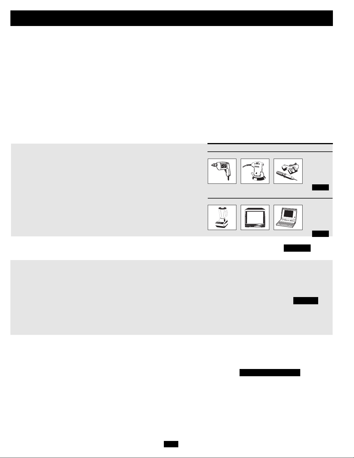
Choix de batterie
Choix du type de batterie auxiliaire (s'il y en a)
Choisir des batteries « à décharge poussée » pour obtenir une performance maximale de votre chargeur-onduleur, Ne pas utiliser de batterie ordinaire de
voiture ou de démarrage ou de batteries notées à intensité de démarrage à froid (Cold Cranking Amps CCA). Si les batteries connectées au chargeur-onduleur ne sont pas de vraies batteries à décharge poussée, leur durée de fonctionnement pourrait être considérablement réduite. Si vous utilisez le même groupe
de batteries pour alimenter le chargeur-onduleur ainsi que les charges CC, votre groupe de batteries devra être calibré adéquatement (des charges plus lourdes exigeront un groupe de batteries avec un plus grande capacité A/h) ou la durée de fonctionnement des batteries pourrait être considérablement réduite.
Les batteries à celulles liquides (ventilées) ou à cellules en gel/ AGM (scellées) sont idéales. Les batteries 6 volts de voiturette de golf, marine à décharge
poussée ou à décharge poussée 8D sont aussi acceptables. Vous devez régler le commutateur DIP de type de batterie du chargeur-onduleur (voir la section
Configuration pour plus de renseignements) pour l'apparier aux types de batteries que vous connectez ou vos batteries pourraient se dégrader ou être endommagées sur une longue période. Dans beaucoup de cas, la batterie du véhicule sera la seule installée. Les batteries auxiliaires doivent être identiques aux batteries du véhicule si elles sont connectées ensemble.
Correspondance de la capacité A/h de la batterie à votre application
Choisir une batterie ou un système de batteries qui fournira à votre chargeur-onduleur un voltage CC approprié et une capacité A/h suffisante pour alimenter votre application. Même si les chargeurs-onduleurs sont hautement efficaces pour la conversion du CC au CA, leur
capacité nominale de sortie est limitée par la capacité totale en A/h des batteries connectées et le support de l'alternateur de votre véhicule
si le moteur est en marche.
• ÉTAPE 1: Détermination du wattage total requis
Additionnez les puissances nominales de tout l'équipement connecté à votre
chargeur-onduleur. Les puissances nominales sont généralement indiquées dans les
manuels d'équipement ou sur les plaques signalétiques. Si votre équipement est
indiqué en ampères, multiplier le nombre d'ampères par 120 pour calculer la puissance. (Exemple : Une perceuse 1/4 po a besoin de 2,5 A. 2,5 A o 120 volts = 300
watts .)
Remarque : Votrechargeur-onduleur sera plus efficace entre 75 % et 80 % de la puissance indiquée sur
la plaque signalétique.
Perceuse 1/4 po
300W + 220W + 20W = 540W
Mélangeur TV couleur Ordinateur portable
Exemple
Outils
Ponceuse orbitale
Appareils
Chargeur d'outil sans fil
• ÉTAPE 2: Détermination de l'intensité de la batterie requise en CC
Divisez le wattage total requis (d'après l'étape 1, ci-dessus) par le voltage de la batterie (12) pour déterminer l'intensité CC requise.
• ÉTAPE 3: Estimation des A/h de batterie requis (pour un fonctionnement
non supporté par l'alternateur)
Multipliez l'intensité requise (d'après l'étape 2, ci-dessus) par le nombre estimé
d'heures du fonctionnement de votre équipement alimenté exclusivement par batterie avant que vous ne deviez recharger vos batteries en CA sur le secteur ou avec
une génératrice. Compensez pour l'inefficacité en multipliant ce chiffre par 1,2. Cela
vous donnera une estimation grossière de la puissance de batterie en A/h (d'une ou
de plusieurs batteries) que vous devrez connecter à votre chargeur-onduleur.
REMARQUE! : La puissance nominale en A/h des batteries est habituellement donnée pour un régime de décharge
de 20 h. Les capacités réelles en A/h sont moindres quand les batteries se déchargent à un régime plus rapide. Par
exemple, des déchargées en 55 minutes fournissent seulement 50 % de leur puissance nominale en A/h, tandis que
les batteries déchargées en 9 minutes ne fournissent que 30 % de leur puissance nominale en A/h.
• ÉTAPE 4 : Estimation de la recharge de batterie requise, selon votre
application
Vous devez laisser vos batteries se recharger assez longtemps pour remplacer
la charge perdue pendant le fonctionnement de l'onduleur ou vous épuiserez
éventuellement vos batteries. Pour estimer la durée minimale de recharge de
vos batteries, selon votre application, diviser la capacité requise en A/h de votre
batterie (d'après l'étape 3, ci-dessus) par l'ampérage nominal de charge de votre
chargeur-onduleur (voir la feuille de spécifications à part).
REMARQUE! : Pour les chargeurs-onduleurs de Tripp Lite fournissant 1 000 watts ou moins d'alimentation CA
continue, une batterie à grande capacité sera normallement suffisamment puissante pour alimenter plusieurs
applications avant qu'une recharge soit nécessaire. Pour les applications mobiles, si une seule batterie est continuellement rechargée par un alternateur à ralenti élevé ou plus rapide, alors il ne sera peut-être pas nécessaire
de la recharger depuis le secteur ou d'une génératrice. Pour les chargeurs-onduleurs de Tripp Lite de plus de 1
000 watts utilisés dans les applications mobiles, Tripp Lite recommande que vous utilisiez au moins deux batteries, rechargées si possible par un alternateur robuste chaque fois que le véhicule est en marche. Les chargeursonduleurs de Tripp Lite vous fourniront une alimentation adéquate pour un usage ordinaire dans des durées limitées sans le support d'une alimentation de secteur ou de génératrice. Cependant, lors du fonctionnement de
charges électriques extrêmement lourdes à leur puissance maximale, vous pourriez avoir envie « d'assister vos
batteries » en faisant tourner une génératrice auxiliaire ou un moteur de véhicule et le faire à une vitesse plus
rapide que le ralenti.
22R
300W + 140W + 100W = 540W
540 watts ÷ 12V = 45 A CC
45 A CC o 5 h. (durée)
1,2 (taux d'inefficacité) = 270 A/h
270 A/h ÷ 55 A
Régime du chargeur-onduleur =
5 heures de recharge
Page 23

)
Montage
MISE EN GARDE! Monter votre chargeur-onduleur AVANT la connexion de la batterie CC et l'alimentation CA. Ne pas suivre ces directives pourrait entraîner des
blessures et/ou des donnages au chargeur-onduleur et aux systèmes connectés.
Tripp Lite fabrique une variété de différents chargeurs-onduleurs avec de nombreuses et différentes options de montage pour les applications sur
des véhicules et autres. Tripp Lite recommande un montage permanent de votre chargeur-onduleur selon l'une des configurations illustrées cidessous. L'utilisateur doit fournir la quincaillerie de fixation et doit déterminer si la quincaillerie et la surface de fixation peuvent supporter le poids
du chargeur-onduleur. Communiquez avec Tripp Lite si vous avez besoin d'aide pour le montage de votre chargeur-onduleur.
Modèles 750 et 1250 Seulement
Qu'il soit monté horizontalement ou verticalement,
l'Inverseur doit être situé dans un compartiment clos,
protégé des conditions météorologiques.
A
À l'aide des mesures du schéma, installer deux attaches de 6 mm
(1/4po) fourni par l'utilisateur dans une surface horizontale rigide en
laissant les têtes dépasser légérement. Glisser le chargeur-onduleur entre les attaches pour engager les fentes de fixation moulées
en bas du boîtier du chargeur-onduleur. Installer et deux attaches de 6 mm (1/4po) fourni par l'utilisateur dans les pieds de fixation
moulés en avant du boîtier du chargeur-onduleur. Le cabinet de
polycarbone et le pied de support de votre circuit inverseur/
chargeur sont suffisamment robustes pour vous permettre un
montage vertical, si le compartiment de votre véhicule requiert
cette configuration. Pour le montage vertical, le panneau de contrôle du circuit inverseur/chargeur doit faire face au haut
C
B
C
Laisser 5 cm (2" po) au moins
de jeu à l'avant et à l'arrière
pour une bonne ventilation.
Tous les Modèles à l'exception des Modèles 750
et 1250
Note: En faisant fonctionner le modèle RV2012UL
marine dans une application marine, se référer au
supplément du manuel de l'utilisateur qui
accompagne ces modèles.
Qu'il soit monté horizontalement ou verticalement,
l'Inverseur doit être situé dans un compartiment clos,
protégé des conditions météorologiques.
A
À l'aide des mesures du schéma, installer deux attaches de 6 mm
(1/4po) fourni par l'utilisateur dans une surface horizontale rigide en
laissant les têtes dépasser légérement. Glisser le chargeur-onduleur vers l'avant par dessus les attaches pour engager les pieds de
fixation moulés en avant du boîtier du chargeur-onduleur. Installer
et fixer des attaches supplémmentaires de 6 mm (1/4po) fourni par
l'utilisateur dans les pieds de fixation moulés à l'arrière et sur les
côtés du boîtier du chargeur-onduleur. *Les pieds arrière se prolongent au-delà du boîtier de l'unité pour fournir une espace de ventilation adéquat derrière le(s) ventilateur(s) de refroidissement; il ne
faut pas les enlever. Le cabinet de polycarbone et le pied de support de votre circuit inverseur/chargeur sont suffisamment
robustes pour vous permettre un montage vertical, si le compartiment de votre véhicule requiert cette configuration. Pour le
montage vertical, le panneau de contrôle du circuit inverseur/
chargeur doit faire face au haut.
Laisser 5 cm (2" po) au moins de jeu à l'avant et à l'arrière pour une bonne ventilation.
B
6.75 in.
(17.1 cm)
7.87 in.
(20 cm)
A
4.5 in.
6.75 in.
(17.1 cm)
(11.4 cm)
M
5.57 in.
B
9.59 in.
(24.35 cm.)
A
Remarque : Les boîtiers modèle VR peuvent avoir différentes caractéristiques du panneau avant.
5.57 in.
(14.16 cm.)
M
1.64 in.
(4.15 cm.)
9.59 in.
(24.35 cm.)
5.87 in.
(14.91 cm.)
(14.16 cm.)
5.87 in.
(14.91 cm.
B
* Tous les modèles possèdent des pieds de fixation à l'avant et
à l'arrière. Les modèles Select possèdent des pieds de
fixation latéraux.
23R
Page 24

Connexion de la batterie
Connexion de votre chargeur-onduleur à vos batteries selon les procédures suivantes :
• Connexion du câblage CC : Puisque
votre chargeur-onduleur est un convertisseur hautement
efficace d'électricité, sa capacité
nominale de sortie
Connecteurs CC
est limitée par la
longueur et le calibre du câblage
reliant la batterie à
l'unité. Uilisez le
câblage le plus
court et du plus
Connecteurs CC doubles (voir
remarque au bas de la page)
gros diamètre (calibre maximal 2/0) pour
fixer aux bornes CC de votre chargeur-onduleur. Un câblage plus court et de plus gros
calibre réduit la baisse de tension CC et permet un transfert maximal de courant. Votre
chargeur-onduleur est capable de délivrer un
wattage de pointe jusqu'à 200 % de sa sortie
de wattage nominal continu pendant de
brèves périodes. Voir la page des spécifications pour les détails. Il faut utiliser un calibre plus gros quand un équipement qui consomme beaucoup fonctionne continuellement dans ces conditions. Serrer vos bornes
de chargeur-onduleur et de batterie à environ 3,5 Newton/mètre de couple pour créer
une connexion efficace et empêcher un
réchauffement excessif à cette connexion.
Un serrage insuffisant des bornes peut
annuler votre garantie. Voir la page des spé-
cifications pour le tableau des tailles minimales de câble recommandées.
• Connexion de mise à la terre : À l'aide
d'un fil de calibre 8 (AWG) ou plus gros,
connectez la cosse principale de mise à la
terre au châssis du véhicule ou à la terre.
Voir la section Identification des caractéristiques pour localiser la cosse principale de
mise à la terre sur votre modèle de chargeuronduleur. Toutes les installations doivent
être conformes aux codes et règlemens
locaux.
• Connexion de fusible : L'article 551 du
code national de l'électricité (NEC) exige
que vous connectiez toutes les bornes CC
positives de votre chargeur-onduleur
directement à des fusibles et des blocfusibles UL à moins de 457 mm (18 po) de
la batterie. Le calibre nominal du fusible
doit être égal ou supérieur au calibre minimal de fusible CC inscrit dans les spécifications de votre CC. Voir les spécifications
pour les recommandations de fusible et de
bloc-fusibles. Voir les schémas ci-dessous
pour l'emplacement correct des fusibles.
MISE EN GARDE! o Ne pas mettre votre chargeur-onduleur à la masse au châssis du véhicule ou à
la terre peut entraîner un risque de choc électrique mortel.
• Ne jamais essayer de faire fonctionner votre chargeur-onduleur en le connectant directement à la
sortie d'un alternateur plutôt qu'à une batterie ou un groupe de batterie.
• Observez la bonne polarité avec toutes les connexions CC.
Véhiculaire
La tension nominale d'entrée CC de votre chargeur-onduleur doit corespondre à la tension de votre ou de vos batteries—12 volts, dans la
plupart des application véhiculaires.
Il est possible de connecter votre chargeur-onduleur à la batterie principale dans le système électrique de votre véhicule. Dans la plupart
des véhicules, le chargeur-onduleur sera connecté à l'une ou plusieurs des batteries auxiliaires (stationnaires) dédiées qui sont isolées du
système de propulsion pour empêcher l'épuisement possible de la batterie principale.
3
7
12 Volts
2
12 Volts
12 Volt Inverter/Charger
5
4
6
2
1
2
12 Volts
12 Volts
5
3
76
24R
7
12 Volt Inverter/Charger
54321
1
12 Volts
Connexion 12 volts de la batterie principale
Connexion (en parallèle isolée) des batteries principale et auxiliaire 12 volt)
Alternateur 12 volts Mise à la terre du véhicule Batterie principale 12 volts Batterie auxiliaire (stationnaire) 12 volts Fusible & bloc-fusibles
UL(monté à moins de 457 mm (18 po) de la batterie) Isolateur de batterte Câblage de gros diamètre, calibre maximal 2/0 Gauge pour s'adapter aux
bornes Fil de mise à la terre calibre 8 AWG (minimum)
REMARQUE : Les modèlesSelect possèdent deux terminaux positifs et deux terminaux négatifs CC. À l'aide de la même architecture de connexion illustrée sur les schémas, relier les deux bornes négatives du chargeur-onduleur à l'unique borne négative de la batterie avec deux câbles de calibre 2/0; relier les deux bornes positives du chargeur-onduleur à l'unique borne positive de la batterie avec
deux câbles de calibre 2/0 par l'intermédiaire de deux fusibles ou bloc-fusibles UL ou équivalent. Utiliser l'équivalent de deux câbles 2/0 pour toutes les autres connexions dans le système de batterie.
Connexion aux deux bornes CC ; Il est acceptable d'utiliser deux câbles pour connecter votre batterie à un seul terminal CC positif et à un seul terminal CC négatif, cependant, votre chargeur-onduleur fournira une alimentation de sortie réduite. Le choix de la borne positive ou négative pour la connexion ne fait aucune différence car les deux bornes positives sont liées à la masse intérieurement comme le sont les deux bornes négatives. Dans cette connexion vous devez relier un câble positif par l'intermédiaire d'un fusible ou d'un bloc-fusibles UL fourni par l'utilisateur.
8
8
8
Page 25

Connexion d'Entrée/Sortie CA
Pour éviter de surcharger votre chargeur-onduleur, faire correspondre les exigences de puissance de l'équipement que vous voulez faire fonctionner en tout temps (additionnez leurs watts) avec la puissance de votre modèle de chargeur-onduleur (voir les spécifications). Ne pas confondre
les puissances nominales de wattage « continu » et de wattage «de pointe ». Le plupart des moteurs électriques ont besoin de plus de puissance
au démarrage (« wattage de pointe ») qu'il n'est nécessaire pour un fonctionnement continu, quelquefois au-delà de 100 % de plus. Certains
moteurs, commes les réfrigérateurs et les pompes, démarrent et s'arrêtent de manière intermittente selon la demande, nécessitant du « wattage de
pointe » à de nombreux moments imprévisibles pendant leur fonctionnement. Caractéristique DoubleBoost™ : Les chargeurs-onduleurs Tripp
Lite peuvent fournir jusqu'à deux fois le wattage nominal de leur plaque signalétique pendant 10 secondes,* fournissant ainsi la puissance nécessaire pour démarrer à froid des outils et de l'équipement lourds. Caractéristique OverPower™ : Les chargeurs-onduleurs Tripp Lite peuvent
fournir jusqu'à 150 % du wattage nominal de leur plaque signalétique pendant 1 heure*, fournissant ainsi beaucoup de puissance de réserve pour
faire fonctionner, plus longtemps de manière fiable, des outils et de l'équipement.
* La durée réelle dépend du modèle, de lâge de la batterie, du niveau de charge de la batterie et de la température ambiante.
Mise en garde! Consulter un électricien qualifié et suivre tous les codes électriques applicables et
les exigences pour une connexion à raccordement fixe. Déconnecter à la fois l'entrée CC et l'alimentation de secteur CA avant d'effectuer un raccordement fixe. Utiliser un fil de type THHN ou
équivalent supportant une température nominale minimale de 90°C .
Connexion des modèles avec bornes à raccordement fixe
Condition De Raccordement De Rendement : L'UL exige que les bornes de
rendement doivent être reliées aux réceptacles de GFCI (série UL-énumérée
requise de réceptacle manufacturer/model : Hubbell GF8300 ou Leviton 6598).
Modèles à simple entrée/sortie
Entrée : Connectez les fils entrants aux bornes vivante (brune) ,
neutre (bleue) et mise à la terre* (verte) 1
3
1
Sortie : Connectez les fils sortants aux bornes vivante (noire) ,
neutre (blanche) et mise à la terre* (verte) 1
Replacer le couvercle et serrer les vis. *Si le tube protecteur entrant ne contient que deux fils (vivant et neutre), il doit être lié à la cosse principale de mise à la terre de l'unité. Dans tous les cas,
le tube protecteur doit être mis à la terre ou à la masse du véhicule et il doit être mis à la masse avec le tube protecteur sortant.
5
1
2
4
2
3
1
4
5
“FOR USE WITH COPPER WIRE ONLY”
HOT IN
NEUTRAL IN
GROUND IN
GROUND OUT
HOT OUT
NEUTRAL OUT
Remarque : Connexion de mise à la terre, fournie.
Modèles à double entrée/sortie
Les modèles Select fournissent une capacité supérieure d'alimentation de dérivation en établissant la connexion deux sources d'entrée séparées. Ces deux sources peuvent être soit deux
lignes de 120 V provenant de la division d'une ligne unique de 240V (les lignes de 120V en
opposition de phase) soit deux différents sourves de 120 V. Le chargeur-onduleur alimentera
seulement la sortie de 120 V et NE fournira PAS de sortie de 240V même si il est connecté
aux entrés d'une ligne partagée de 240 V quand il est en mode de conversion. Qunad le
chargeur-onduleur reçoit une alimentation CA, il peut fournir jusqu'à 30 A aux charges connectées, sur chaque circuit**. Quand le chargeur-onduleur ne reçoit pas d'alimentation CA
et a commuté sur l'alimentation de conversion CC par batterie, il peut fournir différents
niveaux d'ampérages aux charges connectées (voir courant de sortie CA maximal dans la
section spécifications) sur LES DEUX circuits. Les modèles à double entrée/sortie alimentent soit : a) des entrées et sorties à source double; b) une entrée et sortie à source simple; ou c) Une entrée à source simple et des sorties à double source (avec alimention CA de
la sortie 2 disponible seulement en mode de conversion). Connecter comme suit le fil et le
tube protecteur fournis par l'utilisateur aux connexions :
Entrée : Connecter les fils entrants aux fils vivant (noir pour Entrée 1 CA, noir pour Entrée
2 CA), neutre (blanc pour Entrée 1 CA, blanc pour Entrée 2 CA) et de mise à la terre
(vert/jaune).
Sortie : Connecter les fils sortants aux fils vivant ((noir pour Sortie 1 CA, noir pour Sortie
2 CA), neutre (blanc pour Sortie 1 CA, blanc pour Sortie 2 CA) et de mise à la terre
(vert/jaune).
Entrée 1 CA
Entrée 2 CA
Sortie 2 CA
Sortie 1 CA
25R
Page 26

Connexion d'Entrée/Sortie CA
(suite)
Source double Entrée/Sortie*
• L'entrée 1 CA fournira seulement l'alimentation de secteur à la
sortie 1 CA.
• Si vous avez une seule source d'entrée CA 120 V, vous devez la
connecter à l'entrée 1 CA.
Source simple Entrée/sortie*
• L'alimentation convertie par batterie est fournie à la fois à à la
sortie 1 CA et à la sortie 2 CA
• Si vous avez un seul circuit de sortie, vous devez le connecter à
la sortie 1 CA.
• L'entrée 2 CA fournira seulement l'alimentation de secteur à la
sortie 2 CA.
* Connexions Entrée/Sortie source simple ou source double : En plus d'alimenter les charges connectées, l'entrée 1 CA alimente également le chargeur de batterie. Si vous connectez une lourde charge
à la sortie 1 CA, vous devez choisir un réglage plus restrictif du chargeur de batterie (voir « Choix des points limite de chargeur de batterie ») ou vous pourriez expérimenter un déclenchement continuel agaçant du disjoncteur de service électrique (source) qui alimente l'entrée 1 CA. Le chargeur-onduleur mesurera seulement le courant à la sortie 1 CA pour limiter automatiquement le régime
du chargeur. Le courant d'entrée de l'entrée 1 CA passe par la sortie 2 CA sans être mesuré. Connexions Entrée source simple/Sortie source double : Vous pouvez connecter EN 1 CA et EN 2 CA à
une seule source pour alimenter les sorties 1 et 2 CA. Cependant, les charges connectées à la sortie 2 CA ne seront pas mesureés dans le but de limiter automatiquement le chargeur. Il peut en résulter un déclenchement occasionnel du disjoncteur de service électrique (source) Si cela arrive, réduire la charge de la sortie 2 CA jusqu'à ce que le déclenchement agaçant cesse.
** Limité par des disjoncteurs fournis par l'utilisateur.
Service
Avant d'envoyer votre chargeur-onduleur pour réparations, suivre ces étapes; 1.) Relire les directives d'installation et de fonctionnement pour
s'assurer que le problème n'a pas pour origine une mauvaise lecture de ces directives. Vérifier également que les disjoncteurs ne sont pas
déclenchés. *2.) Si le problème persiste, ne pas communiquer avec le vendeur ou lui renvoyer le chargeur-onduleur. À la place, appeler Tripp
Lite au (773) 869-1233. Un technicien des réparations vous demandera le numéro de modèle du chargeur-onduleur, son numéro de série et
sa date , et essaiera de régler le problème au téléphone. 3.) Si le problème nécessite une réparation, le technicien vous émettra un numéro
d'autorisation de retour de matériel (RMA) exigée pour une réparation. Emballer soigneusement le chargeur-onduleur pour éviter des dommages pendant l'expédition. Ne pas utiliser de billes de styrofoam pour emballer. ** Tout dommage (direct, indirect, spécial, accidentel ou
fortuit) arrivé au chargeur-onduleur pendant le transport à Tripp Lite ou à un centre de service autorisé Tripp Lite est exclu de la garantie.
Les frais de transport des chargeurs-onduleurs envoyés à Trip Lite ou à un centre de service autorisé Tripp Lite doivent être prépayés. Inscrire
le numéro de RMA sur le paquet. Si le chargeur-onduleur est encore sous garantie, joindre une copie de votre facture. Renvoyer le chargeuronduleur pour réparation par un transporteur assuré à l'adresse que vous a donné le technicien de service de Tripp Lite.
*C'est la cause la plus courante des demandes de service à laquelle on peut remédier facilement en suivant les directives de remise en marche dans ce manuel. **Si vous avez besoin d'un emballage, le technicien peut vous faire envoyer un emballage approprié.
Entretien
Votre chargeur-onduleur ne requiert aucun entretien et ne contient aucune pièce réparable ou remplaçable par l'utilisateur, mais il doit être
maintenu au sec en tous temps. Vérifier périodiquement, nettoyer et reserrer toutes les connexions de câble, si nécessaire, à la fois de l'unité et de la batterie.
26R
Page 27

Dépannage
Essayez ces solutions aux problèmes courants du chargeur-onduleur avant d'appeler pour une assistance. Communiquez avec le service à la
clientèle de Tripp Lite au (773) 869-1234 avant de renvoyer votre unité pour réparation.
SYMPTÔME PROBLÈMES CORRECTIONS
Pas de sortie CA L'unité n'est pas correctement branché sur le secteur. Brancher l'unité sur le secteur.
(Les trois voyants indicateurs sont éteints) Le commutateur de mode de fonctionnement est à Mettre le commutateur de mode de fonctionnement sur
La batterie ne se recharge pas Les batteries connectées sont mortes. Vérifier et remplacer les vieilles batteries.
(Entrée CA présente) Le fusible* de la batterie a sauté. Vérifier et remplacer le fusible*.
Les trois DEL « BATT VOLT/CHRG CURR » La batterie est trop déchargée. L'unité s'éteindra pour Utiliser un chargeur* auxiliaire pour relever la tension de la
clignotent lentement (éclair au 1/2 seconde) empêcher des dommages à la batterie. batterie. Vérifier les connexions externes de la batterie et le fusible.
avec lecommutateur de mode de L'unité se réarme automatiquement quand la condition est levée.
fonctionnement sur " AUTO/REMOTE ".
Les trois DEL « BATT VOLT/CHRG CURR » La batterie est trop chargée. L'unité s'éteindra pour Déconnecter tous les chargeurs auxiliaires. Réarmer en mettant le
clignotent rapidement (éclair au 1/4 empêcher des dommages à la batterie. Le problème peut commutateur de mode de fonctionnement sur « OFF ». Attendre une
seconde) avec le commutateur de mode provenir des chargeurs auxiliaires connectés ou du minute et commuter sur « AUTO/REMOTE ». Si l'unité reste en
de fonctionnement sur « AUTO/REMOTE ". chargeur de l'unité. mode d'arrêt après plusieurs tentatives de réarmemant,
Le voyant indicateur « LOW » de la batterie La tension de la batterie est basse. L'unité s'est éteinte pour Si l'alimentation AC (de secteur ou d'une génératrice) est présente,
clignote avec le commutateur de mode protéger la batterie de dommages. l'unité se réarmera automatiquement et commencera à recharger
de fonctionnement sur « AUTO/REMOTE ». les batteries connectées. Cependant, si un chargeur externe
Le voyant indicateur de fonctionnement L'onduleur est en surcharge. L'unité s'éteindra après 5 Réduire la charge. Réarmer en mettant le commutateur de mode
« LOAD » rouge clignote secondes. de fonctionnement sur « OFF ». Attendre1 minute. Commuter sur
* fourni par l'utilisateur.
« OFF » et l'entrée CA est présente. « AUTO/REMOTE » ou « CHARGE ONLY ».
C'est normal lorsque le commutateur de mode de Aucune correction requise. La sortie CA reviendra quand l'entrée
fonctionnement est sur « CHARGE ONLY » CA reviendra. Mettre le commutateur de mode de fonctionnement sur
et qu'il n'y a pas entrée CA « AUTO/REMOTE » si vous avez besoin de sortie CA.
Le disjoncteur du circuit a sauté. Réarmer le disjoncteur.
L'unité s'est éteinte à cause d'une surcharge (empêchant Déconnecter tous les chargeurs auxiliaires. Réarmer en mettant le
des dommages à la batterie) Le problèem peut être avec les commutateur de mode de fonctionnement sur « OFF ». Attendre une
chargeurs auxiliaires connectés ou avec le chargeur de l'unité. minute et passez sur « AUTO/REMOTE » ou « CHARGE ONLY ». Si
L'unité s'est éteinte à cause d'une décharge excessive de la Utilisez un chargeur* auxiliaire pour relever la tension de la batterie.
batterie. Vérifier les connexions externes de la batterie et le fusible. L'unité
L'unité s'est éteinte à cause d'une surcharge. Réduire la charge. Réarmer en mettant le commutateur de mode
Le câblage* de la batterie est lâche. Vérifier et resserrer ou remplacez le câblage*.
L'unité s'est éteinte à cause d'une surcharge (empêchant Déconnecter tous les chargeurs auxiliaires. Réarmer en mettant le
des dommages à la batterie) Le problème peut provenir des commutateur de mode de fonctionnement sur « OFF ». Attendre une
chargeurs auxiliaires connectés ou du chargeur de l'unité. minute et commuter sur « AUTO/REMOTE » ou « CHARGE ONLY ».
Le disjoncteur du circuit a sauté. Réarmer le disjoncteur.
Mauvaise lecture à cause d'un câblage CC insuffisant Utiliser un câble CC de calibre suffisant bien connecté au
ou mal connecté. chargeur-onduleur.
l'unité reste en mode d'arrêt après plusieurs tentatives de réarmement,
communiquez avec le service à la clientèle de Tripp Lite pour de l'aide.
se réarme automatiquement quand la consition est levée.
de fonctionnement sur « OFF ». Attendre1 minute. Commuter sur
« AUTO/REMOTE » ou « CHARGE ONLY ».
Si l'unité reste en mode d'arrêt après plusieurs tentatives de
réarmement, communiquez avec le service à la clientèle de Tripp
Lite pour de l'aide.
communiquez avec le service à la clientèle de Tripp Lite pour de l'aide.
est utilisé pour recharger les batteries, vous devrez réarmer
manuellement l'unité en mettant le commutateur de mode de
fonctionnement sur « OFF » pendant deux secondes avant de
revenir sur « AUTO/REMOTE ».
« AUTO/REMOTE » ou « CHARGE ONLY ».
27R
Page 28

1111 W. 35th Street, Chicago, IL 60609 USA
Support à la clientèle : (773) 869-1234
www.tripplite.com
200605181 93-2556
Page 29

Inverter/Charger DC Volt: 12
Twin 00 (2/0)
Watts 6 4 2 0 00 (2/0) (RV2012OEM & RV3012OEM only)
500 15 ft 25 ft 39 ft 62 ft 79 ft 158 ft.
700 11 ft 18 ft 28 ft 44 ft 56 ft 112 ft.
1000 N/R 12 ft 20 ft 31 ft 39 ft 78 ft.
2000 N/R N/R N/R 16 ft 20 ft 40 ft.
2400 N/R N/R N/R 13 ft 16 ft 32 ft.
3000 N/R N/R N/R 10 ft 13 ft 26 ft.
†
N/R = Not Recommended. NOTE: Acceptable power is directly related to cable length (i.e. - the shorter the cable, the better the performance)
Minimum Recommended DC Cable Sizing Chart
†
Use in conjunction with DC wiring connection instructions in the Battery Connection section.
Specifications
(English)
Model Number: RV750ULHW RV1250ULHW RV2012UL RV2012OEM RV3012OEM
Series Number: AGAP5088 AGAP5094 AP5626 AGAP200012MVP3 AGAP4669
AC Input Connection: Hardwire Hardwire Hardwire Hardwire Hardwire
INVERTER
Common Specifications for All Models: •
DC Input Volts (Nominal): 12 VDC • · DC Input Voltage Range: 10 - 15 VDC • Output Volts (Nominal): 120 VAC, ± 5% • Output Frequency (Nominal): 60 Hz, ± 0.5% • Efficiency: 88% to 94%,
depending on load and temperature
Tripp Lite Inverter/Chargers include a Battery Charge Conserver (Load Sense) Control which saves battery power by allowing users to set the minimum load level at which the unit’s
inverter turns on. Users can significantly reduce the No Load DC Input Current (approximately 1 to 3 A for all models) to a very low amp level with the use of this control.
Continuous Power (@ 20 C ): 750 1250 2000 2000 3000
OverPower™Peak Surge Power:* 1125 1875 3000 3000 4500
DoubleBoost™PeakSurge Power:* 1500 2500 4000 4000 6000
Maximum Output AC Current 6.3 A 10.4 A 16.7 A 16.7 A 25 A
Continuous
UL-Recognized DC Fuse 125 A 200 A two 175 A two 175 A two 275 A
Required
DC Input Current @
Nominal V DC Full Load: 73 A 117 A 190 A 185 A 282 A
BATTERY CHARGER
Common Specifications for All Models •
Acceptance Volts VDC: (Wet** / Gel) 14.4 V** / 14.2 V • Float Volts DC (w/gel): 13.3 V (13.6 V) • · Input Volts (Nominal): 120 VAC
Charging Capacity DC: 45 A** / 11 A 55 A** / 14 A 100 A** / 25 A 100 A** / 25 A 140 A** / 35 A
Input Current AC: 8.2 A 11 A 20 A 21 A 25 A
LINE VAC OPERATION
Common Specifications for All Models •
Input Frequency (Nominal): 60 Hz, ±10%•Maximum Input Volts (Transfer to Battery) 145 VAC Except OEM Models (Selectable 145V**/135V)
Minimum Input Volts: Selectable 75**, 85, 95 or 105 VAC Selectable 75**, 85, 95 or 105 VAC Selectable 75**, 85, 95 or 105 VAC Selectable 75**, 85, 95 or 105 VAC Selectable 75**, 85, 95 or 105 VAC
Transfer to Battery
Maximum Input AC Current 30 A 33 A 38 A 43 A 30 A
(Continuous, Charger at Maximum):
Maximum Bypass AC Current: 20 A 20 A 30 A 20/20 A 20/20 A
* OverPower duration (up to 1 hour). DoubleBoost duration (up to 10 seconds). Actual duration depends on battery age, battery charge level and ambient temperature. **Factory setting.
The policy of Tripp Lite is one of continuous improvement. Specifications are subject to change without notice.
Wire Gauge vs. Maximum Distance from Unit to Battery
Note on Labeling Two symbols are used on the RV labels.
V~: AC Voltage V : DC Voltage
1111 W. 35th Street, Chicago, IL 60609 USA
Customer Support: (773) 869-1234
www.tripplite.com
Page 30

Spécifications
(Français)
NUMÉRO DE MODÈLE : RV750ULHW RV1250ULHW RV2012UL RV2012OEM RV3012OEM
Numéro de série : AGAP5088 AGAP5094 AP5626 AGAP200012MVP3 AGAP4669
Connexion d'entrée CA Raccordement fixe Raccordement fixe Raccordement fixe Raccordement fixe Raccordement fixe
ONDULEUR
Spécifications courantes pour tous les modèles :
• Tension d'entrée CC (nominale) : 12 V CC • Plage de tension d'entrée CC : 10 - 15 V CC • Tension de sortie CA (nominale) : 120 VAC, ± 5% • Fréquence de sortie (nominale) : 60
Hz, ± 0.5% • Efficacité: 88 % à 94 %, dépendant de la charge et de la température
Les chargeurs-onduleurs de Tripp Lite sont équipés d'une commande de conservation de charge de batterie (détecteur de charge) qui économise la batterie en permettant à l'utilisateur de régler le niveau de charge minimal auquel l'onduleur de l'unité se met en marche. Les utilisateurs peuvent réduire le courant d'entrée CC sans charge (environ 1 à 3 A pour tous les modèles) à un niveau très bas à l'aide de cette commande.
Alimentation continue (@ 20° C) : 750 1250 2000 2000 3000
Puissance de surtension 1125 1875 3000 3000 4500
depointe OverPower™:*
Puissance de surtension de 1500 2500 4000 4000 6000
pointe Double Boost™:*
Courant CA de sortie maximal 6.3 A 10.4 A 16.7 A 16.7 A 25 A
(Continu) :
Fusible CC homologué 125 A 200 A deux 175 A deux 175 A deux 275 A
UL requis
Courant d'entrée CC @ la tension
nominale CC en pleine charge : 73 A 117 A 190 A 185 A 282 A
CHARGEUR DE BATTERIE
Spécifications courantes pour tous les modèles
• Acceptation de tension CC : (Liquide** / Gel )14.4 V** / 14.2 V • Tension flottante CC (liq./gel) : 13.3 V (13.6 V) • Tension d'entrée (nominale) : 120 V CA
Capacité de charge CC: 45 A** / 11 A 55 A** / 14 A 100 A** / 25 A 100 A** / 25 A 140 A** / 35 A
Courant d'entrée CA: 8.2 A 11 A 20 A 21 A 25 A
FONCTIONNEMENT DE LA LIGNE CA
Spécifications courantes pour tous les modèles
• Fréquence d'entrée (nominale) : 60 Hz, ±10% Tension d'entrée maximale (transfert à la batterie) 145 V CA Excepté les modèles OEM (145V**/135V sélectionnable)
Tension minimale d'entrée : Sélectionnable 75**, 85, 95 ou 105 V CA Sélectionnable 75**, 85, 95 ou 105 VCA Sélectionnable 75**, 85, 95 ou 105 V CA Sélectionnable 75**, 85, 95 ou 105 V CA Sélectionnable 75**, 85, 95 ou 105 VCA
(Transfert à la batterie)
Courant maximal d'entrée 30 A 33 A 38 A 43 A 30 A
(Continu, chargeur au maximum) :
Courant maximal CA de dérivation : 20 A 20 A 30 A 20/20 A 20/20 A
* Durée OverPower (jusqu'à 1 heure). Durée DoubleBoost (jusqu'à 10 secondes). La durée réelle dépend de l'âge de la batterie, de son niveau de charge et de la température ambiente. **Réglage d'usine.
Tripp Lite a une politique d'amélioration continue. Les spécifications sont sujettes à modification sans préavis.
Tension CC du chargeur-onduleur : 12 V
Double 00 (2/0)
Watts 6 4 2 0 00 (2/0) (RV2012OEM & RV3012OEM seulement)
500 15 pi. 25 pi. 39 pi. 62 pi. 79 pi. 158 pi.
700 11 pi. 18 pi. 28 pi. 44 pi. 56 pi. 112 pi.
1000 N/R 12 pi. 20 pi. 31 pi. 39 pi. 78 pi.
2000 N/R N/R N/R 16 pi. 20 pi. 40 pi.
2400 N/R N/R N/R 13 pi. 16 pi. 32 pi.
3000 N/R N/R N/R 10 pi. 13 pi. 26 pi.
†
N/R = Non Recommandé. REMARQUE: La puissance acceptable est directement relativeà la longueur du câble; plus le câble est court,
meilleure est la performance)
Tableau des calibres minimaux de câble CC recommandés
†
À utiliser selon les directives de câblage CC dans la section Connexion de la batterie.
Calibre du fil vs. la distance maximale de l'unité à la batterie
Remarque sur l'étiquetage Deux symboles sont utilisés sur les étiquettes de VR.
V~: Voltage CA V : Voltage CC
200607168 93-2592
1111 W. 35th Street, Chicago, IL 60609 USA
Support à la clientèle : (773) 869-1234
www.tripplite.com
 Loading...