

Page 1

1778
Owner’s Manual
1111 W. 35th Street Chicago, IL 60609 USA
Customer Support: (773) 869-1234 • www.tripplite.com
Important Safety Instructions
2
Mounting
3
Connection
5
Basic Operation
7
Storage and Service
10
Copyright © 2002 Tripp Lite. All rights reserved. SmartPro®is a registered trademark of Tripp Lite.
SmartPro®RMX
1000-2000 VA
120V Input/Output UPS Systems
Intelligent • Line-Interactive • Industrial Cabinet
Specifications
10
200208099 93-2040 SM1000RMX Owner’s Manual.qxd 9/12/2002 3:53 PM Page 1
U
CUS
L
Page 2
2
UPS Location Warnings
• Use caution when lifting UPS. Because of the considerable weight of all 3U Rackmount
UPS systems, at least two people should assist in lifting and installing them.
• Install your UPS indoors, away from excess moisture or heat, conductive contaminants,
dust or direct sunlight.
• For best performance, keep the indoor temperature between between 32º F and 104º F
(0º C and 40º C).
• Leave adequate space around all sides of the UPS for proper ventilation.
UPS Connection Warnings
• The UPS contains its own energy source (battery). The output terminals may be live even
when the UPS is not connected to an AC supply.
• Connect your UPS directly to a properly grounded AC power outlet. Do not plug the
UPS into itself; this will damage the UPS.
• Do not modify the UPS's plug, and do not use an adapter that would eliminate the UPS’s
ground connection.
• Do not use extension cords to connect the UPS to an AC outlet.
• If the UPS receives power from a motor-powered AC generator, the generator must
provide clean, filtered, computer-grade output.
Equipment Connection Warnings
• Do not use Tripp Lite UPS Systems for life support devices in which a malfunction
or failure of a Tripp Lite UPS System could cause failure or significantly alter the
performance of that device.
• Do not connect extension cords or surge suppressors to the output of your UPS. This
may damage your UPS and will void both the surge suppressor and UPS warranties.
Battery Warnings
• Your UPS does not require routine maintenance. Do not open your UPS for any reason
except battery replacement. There are no user-serviceable parts inside.
• Battery replacement must be performed by qualified service personnel. Because the
batteries present a risk of electrical shock and burn from high short-circuit current,
observe proper precautions. Unplug and turn off the UPS before performing battery
replacement. Use tools with insulated handles, and take caution that the battery terminals
do not contact the metal housing of the UPS. Replace the existing batteries with the
same number and type of new batteries (Sealed Lead-Acid). Do not open the batteries.
Do not short or bridge the battery terminals with any object.
• The UPS batteries are recyclable. Refer to local codes for disposal requirements, or in
the USA only call 1-800-SAV-LEAD for recycling information. Do not dispose of the
batteries in a fire.
• Do not attempt to add external batteries to your UPS system.
SAVE THESE INSTRUCTIONS
This manual contains instructions and warnings that should be followed during the
installation, operation and storage of all Tripp Lite UPS Systems. Failure to heed these
warnings will void your warranty.
Important Safety Instructions
200208099 93-2040 SM1000RMX Owner’s Manual.qxd 9/12/2002 3:53 PM Page 2
Page 3
3
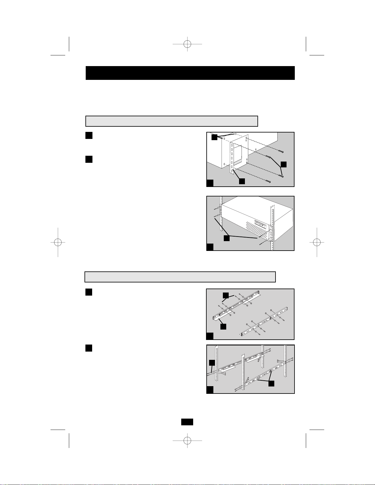
Your UPS may be rackmounted in 4- or 2-post racks using these suggested mounting procedures.
These procedures are for common rack types and may not be appropriate for all rack configurations.
User must determine the fitness of rackmount hardware and procedures before mounting.
1
1
2
Attach mounting ears (A) to the front mounting
holes of the UPS (B) using the screws provided (C).
Have an assistant lift the UPS and hold it in
position with the mounting ears flush against
the rack’s side supports. Mount the UPS by
screwing user-supplied rack bolts (D) through
its mounting ears, and into the rack’s side
supports.
2
Suggested Rackmount Installation for the SM1000RMX
Mounting
Suggested 4-Post Rackmount Installation for the SM2000RMX
1
Connect the three segments of each shelf (A)
using the included screws, nuts and washers
(B). Leave the screws slightly loose so that
the shelves can be adjusted in the next step.
Adjust each shelf to fit your rack, then mount
them in the lowest available space of your
rack with with the screws, nuts and washers
provided (C). Note that the support ledges
should face inward. Tighten the screws that
connect the shelf segments (B).
2
1
2
A
B
C
B
A
B
C
D
200208099 93-2040 SM1000RMX Owner’s Manual.qxd 9/12/2002 3:53 PM Page 3
Page 4
4
Mounting
continued
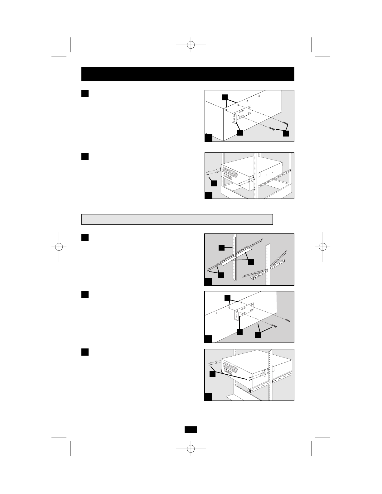
Suggested 2-Post Rackmount Installation for the SM2000RMX
Attach mounting ears (D) to the front mounting
holes of your UPS (E) using the screws provided
(F). Do not attach the mounting ears to your
equipment’s middle holes.
Using an assistant if necessary, lift your
equipment and slide it onto the mounting
shelves. Attach your equipment to the rack by
passing the user-supplied screws, nuts and
washers (G) through its mounting ears and
into the rack rails.
3
1
Attach the four mounting shelf segments
shown (A) to both rack posts (B) with the
screws, nuts and washers provided (C). Note
that the side supports should face inward.
Attach mounting ears (D) to the middle mounting
holes of your UPS (E) using the screws and
washers provided (F). Do not attach the
mounting ears to your equipment’s front holes.
Using an assistant if necessary, lift your UPS
and slide it onto the mounting shelves. Attach
your UPS to the rack by passing the user-supplied screws, nuts and washers (G) through
its mounting ears and into the rack rails.
2
3
1
2
3
B
A
C
E
D
F
G
4
3
4
E
D
F
G
200208099 93-2040 SM1000RMX Owner’s Manual.qxd 9/12/2002 3:53 PM Page 4
Page 5

5
Plug your UPS’s line cord into an
electrical outlet.
Your UPS must be connected directly to a 3wire grounded AC receptacle. Do not use
extension cords with your UPS.
Once your UPS is plugged in, the UPS will
enter STANDBY mode. The fan will activate
and the “ ” LED will begin flashing. The
UPS system’s outlets will not be active until
the UPS is turned ON.
Plug your equipment into your UPS.
Your UPS is designed to support only computer
equipment. You will overload your UPS if you
connect household appliances, laser printers
or surge suppressors to the UPS’s outlets.
Turn your UPS ON
• Press the “POWER” button
• Hold the button for a moment, until the
“ ” LED stops flashing and illuminates
constantly
• Release the button
Your UPS is now ON and its AC outlets
are active.
Connection
1
3
2
SM2000RMX plug (NEMA L5-20P) shown
SM1000RMX shown
SM2000RMX shown
1
2
3
200208099 93-2040 SM1000RMX Owner’s Manual.qxd 9/12/2002 3:53 PM Page 5
Page 6

6
Connection
optional
Your UPS will function properly without these
connections.
DB9 Port Connection
Using the DB9 cable provided, connect a DB9
port on your computer to a DB9 port on your
UPS. Install the Tripp Lite power protection
software appropriate to its operating system.
If your UPS has two DB9 ports, a second
computer with a DB9 port may be connected
if desired.
USB Port Connection
Using the USB cable provided, connect a USB
port from a computer to a USB port on your
UPS. Install the Tripp Lite power protection
software appropriate to its operating system.
If your UPS has two USB ports, a second
computer with a USB port may be connected
if desired.
EPO Port Connection
(Select Models Only)
Using the RJ11 cable provided, connect the
Emergency Power Off (EPO) port of your
UPS to a user-supplied normally closed or
normally open switch according to the circuit
diagram below. The EPO port is not a phone
line surge suppressor; do not connect a phone
line to this port.
EPO Circuit Diagrams
(UPS will turn off if EPO cord is cut or EPO plug is disconnected)
1
2
3
1
2
3
SM1000RMX shown
SM1000RMX shown
SM2000RMX shown
200208099 93-2040 SM1000RMX Owner’s Manual.qxd 9/12/2002 3:53 PM Page 6
Page 7

7
Use the POWER button to switch your UPS between its four modes
of operation.
OFF: No indicator lights are on. The UPS is completely shut down for
storage or shipping. If the UPS is connected to AC power, it will start up in
STANDBY mode. If the UPS is not connected to AC power and the
POWER button is pressed for two seconds, the UPS will “cold start”
into INVERT mode.
STANDBY: The “ ” light is flashing. The UPS is receiving AC power
and using it to charge its batteries, but its outlets are not active. Pressing
the POWER button while the UPS is in STANDBY mode will put the
UPS in the ON mode. Unplugging the UPS or cutting AC power while
the UPS is in STANDBY mode will put the UPS in the OFF mode.
ON: The “ ” light is on. The UPS is receiving AC power, charging
its batteries and delivering power to connected equipment. If AC
power is lost while the UPS is ON (i.e. a blackout occurs), the UPS
will switch into INVERT mode. Pressing the POWER button while
the UPS is ON will put the UPS in STANDBY mode.
INVERT: The “ ” light is flashing. The UPS is powering connected
equipment from battery backup. If AC power is restored, the UPS will
switch to the ON mode. Pressing the POWER button while the UPS
is in INVERT will put the UPS into the OFF mode. If the UPS is in
INVERT mode and its batteries are drained, the UPS will switch to the
OFF mode until AC power is restored, then switch to the ON mode.
Use the MUTE/TEST button to do two things:
SILENCE ALARM: Your UPS has three alarms. The first, the
INVERT alarm, emits four short beeps every ten seconds when the UPS is
in INVERT mode, to warn you that AC power has failed. The second, the
OVERLOAD alarm, emits short, rapid beeps when the UPS is in
INVERT mode if the total power draw of connected equipment exceeds
the UPS’s output capacity, to warn you to reduce the load. The third, the
Low Battery alarm, emits a constant beep when the UPS is in INVERT
mode and its batteries are very nearly depleted, to warn you that connected
equipment must be shut down. To silence the INVERT or OVER-
LOAD alarms, press the MUTE/TEST button. The LOW BATTERY
alarm will only stop when the UPS switches to the OFF or ON mode.
SELF-TEST BATTERIES AND ALARMS: If your UPS is in the
ON mode and has a load connected, you may test its batteries by
pressing the MUTE/TEST button for two seconds. The UPS will
switch to INVERT mode for several seconds. Normally, the INVERT
alarm (four short beeps) will sound, indicating that the system is
working properly. If the OVERLOAD alarm (short, rapid beeps)
sounds, reduce the load on the UPS. If the LOW BATTERY alarm (a
constant beep) sounds, your UPS’s batteries may need replacing or the
batteries may simply be less than fully charged. Let the UPS charge for 12
hours, then perform a second self-test. If the LOW BATTERY alarm
sounds again, contact Tripp Lite for service. Do not unplug your UPS to
test its batteries, or you will remove safe electrical grounding and may
introduce a damaging surge into your network connections.
Basic Operation
Buttons (Front Panel)
200208099 93-2040 SM1000RMX Owner’s Manual.qxd 9/12/2002 3:53 PM Page 7
Page 8

8
Basic Operation
continued
Indicator Lights (Front Panel)
POWER: Lights green when the UPS is receiving AC power.
Illuminates constantly when the UPS is in the ON mode, indicating
that batteries are charging and connected equipment is receiving filtered
AC power. Flashes while in STANDBY mode to indicate that batteries
are charging but connected equipment is not receiving power.
VOLTAGE CORRECTION: Lights green whenever your UPS is
automatically correcting high or low AC line voltage. The UPS will
also click. These are normal, automatic UPS operations, and no
action is required on your part.
BATTERY CHARGE: This multicolored light displays 7 separate
UPS battery charge conditions. It will turn from red (low) to yellow
(medium) to green (full) to show you the level of battery charge. If
the light is constant, your UPS is in the ON or STANDBY mode,
operating from line power, and the battery is charging. If the light is
flashing, your UPS is in the INVERT mode, operating from battery,
and the battery is discharging. If the light is flashing red, your UPS is
in INVERT and is nearly out of power: you should save files and shut
down your equipment immediately.
OUTPUT LOAD: This multicolored light shows how heavy your
UPS’s load is. Steady green indicates a light load, steady yellow a
medium load. When the light is red, your UPS is supporting a load
above 85% of its capacity. If the red light begins flashing, then your
UPS is severely overloaded. Immediately remove load from the UPS
until the light stops flashing.
BATTERY WARNING: Lights red if your UPS’s self-test (initiated
with the Mute/Test Switch) reveals a low battery charge or internal
fault. If this light turns on, let the UPS charge for 12 hours then perform
a second self-test. If the light stays on, contact Tripp Lite for service.
AC Receptacles:Your UPS has 15-amp outlets that provide 120V AC
power. These output receptacles supply your connected equipment
with AC line power during normal operation and battery power during
blackouts and brownouts. The UPS protects equipment connected to
these receptacles against damaging surges and line noise. If you have
a DB9 or USB connection to your UPS, you can remotely reboot connected equipment by turning the UPS OFF and ON using Tripp Lite’s
PowerAlert Software. See software instructions for details.
Other UPS Features (Rear Panel)
15 amp NEMA 5-15R
200208099 93-2040 SM1000RMX Owner’s Manual.qxd 9/12/2002 3:53 PM Page 8
Page 9

Basic Operation
continued
Other UPS Features (Rear Panel)
Ground Screw (Select Models Only): Use this to connect any equipment that requires a chassis ground.
Smart DB9 Ports: Your UPS has one or two DB9 ports that may be
used to connect the UPS to a DB9 port on any workstation or server.
Use with Tripp Lite cabling and PowerAlert Software to monitor and manage network power and automatically save open files and shut down
equipment during a blackout (see Connection.) The DB9 port labeled
“SNMP Config” is also used to configure Tripp Lite SNMP Adapters.
Smart USB Ports: Your UPS has one or two USB ports that may be
used to connect the UPS to a USB port on any workstation or server.
Use with Tripp Lite cabling and PowerAlert Software to monitor and
manage network power and automatically save open files and shut
down equipment during a blackout (see Connection, page 5).
EPO (Emergency Power Off) Port (Select models only): Your UPS
may have an EPO port that can be used to connect the UPS to a contact closure switch to enable emergency inverter shutdown (see
Connection, page 5).
Accessory Slot (Select models only): Remove the small cover panel
from this slot to use optional accessories to remotely monitor and
control your UPS. Contact Tripp Lite at (773) 869-1234 for more
information, including a list of available SNMP, network management
and connectivity products.
Input Breaker: Your UPS has an input breaker that protects your
UPS from overload. If the breaker button trips, remove some of the load
from the UPS’s receptacles and allow the unit to cool before resetting the
breaker button by pressing it.
Battery Door: Qualified service personnel can remove this plate to
remove and replace the UPS batteries. All Battery Warnings must be
observed (see Important Safety Warnings, page 2).
9
200208099 93-2040 SM1000RMX Owner’s Manual.qxd 9/12/2002 3:53 PM Page 9
Page 10

Storage & Service
Before storing your UPS, disconnect all equipment to avoid battery drain, then place the UPS in
the OFF mode by putting it in STANDBY mode, then unplugging it (see Basic Operation, page 7).
If you store your UPS for an extended period of time, recharge the UPS batteries once every three
months by following Steps 1 and 2 in the Connection section (page 5) and allowing the UPS to
charge its batteries for 4-6 hours before placing it back in storage. If you leave your UPS
batteries discharged for an extended period of time, they will suffer a permanent loss of capacity.
If returning your UPS for service, contact your local Tripp Lite dealer or distributor. They will
refer you to a service center. Please carefully pack the UPS using the ORIGINAL PACKING
MATERIAL that came with the unit. Enclose a letter describing the symptoms of the problem.
If the UPS is within the 2 year warranty period, enclose a copy of your sales receipt.
Model SM1000RMX SM2000RMX
Series AGSM1000IG30 AGSM2200Y2U29
Output Capacity (VA/Watts): 1000/750 2000/1300
Battery Runtime in Minutes (Half Load/Full Load): 33/13 53/23
Battery Recharge Time: 2-4 hrs. 2-4 hrs.
Approvals: UL, cUL UL, cUL
Input Voltage (120V); Input Frequency (60 Hz); Online Input Voltage Range (79-147 volts);Voltage-Regulated
Output Voltage Range (120 ±9%); On-Battery Output Voltage Range (120 ±5%); Output Waveform Line Mode
(filtered sinewave);Output Waveform Battery Mode (PWM sine wave); AC Surge Suppression (exceeds IEEE
587 Cat. A & B standards); AC Noise Attenuation (>40 dB); AC Surge Protection Modes (H to N, H to G, N to G).
This device complies with part 15 of the FCC Rules.Operation is subject to the following two conditions:(1) This
device may not cause harmful interference, and (2) this device must accept any interference received, including
interference that may cause undesired operation.
Note:This equipment has been tested and found to comply with the limits for a Class A digital device, pursuant to
part 15 of the FCC Rules.These limits are designed to provide reasonable protection against harmful interference
when the equipment is operated in a commercial environment.This equipment generates, uses and can radiate
radio frequency energy and, if not installed and used in accordance with the instruction manual, may cause
harmful interference to radio communications.Operation of this equipment in a residential area is likely to cause
harmful interference in which case the user will be required to correct the interference at his own expense.
Tripp Lite has a policy of continuous improvement. Specifications are subject to change.
Specifications
Storage
Service
10
200208099 93-2040 SM1000RMX Owner’s Manual.qxd 9/12/2002 3:53 PM Page 10
Page 11

11
200208099 93-2040 SM1000RMX Owner’s Manual.qxd 9/12/2002 3:53 PM Page 11
Page 12

93-2040 (200208099)
200208099 93-2040 SM1000RMX Owner’s Manual.qxd 9/12/2002 3:53 PM Page 12
 Loading...