

Page 1

Owner’s Manual
Reliable AC Power Wherever You Need It
Congratulations! You've purchased a high-quality Inverter designed to function as a mobile energy source powered by your automotive battery.
PowerVerter Inverters convert 12V DC (battery) power into 120VAC (household) power, allowing you to use equipment you commonly use at
home—computers, appliances, electronics, power tools and more—while traveling by automobile or working at remote locations that lack AC
power. PowerVerter Inverters include advanced features that protect your equipment, lengthen the service life of your battery and ensure that
you'll always have battery power to start your vehicle:
PowerVerter
®
DC-to-AC Inverter
Model: PV700HF
Input Output
12V DC 120V, 60Hz AC
1111 W. 35th Street, Chicago, IL 60609 USA
Customer Support: (773) 869-1234
www.tripplite.com
Copyright © 2007 Tripp Lite. PowerVerter®is a registered trademark of Tripp Lite. All rights reserved.
Contents
• Automatic Overload Protection
• Automatic Low Battery Protection
• High-Performance DC-to-AC Inversion
• Frequency-Controlled Output Power
• Simple, Maintenance-Free Operation
• Moisture-Resistant Construction*
• 3 AC Outlets
* The inverter is moisture-resistant, not waterproof.
Important Safety Instructions
Limited Warranty and Warranty Registration
Feature Identification
Operation
Battery Selection
Mounting
Battery Connection
Service/Maintenance
Español
Français
2
6
3
3
4
4
5
5
7
14
Specifications
6
Warranty
Registration:
register online today for a chance
to win a FREE Tripp Lite product—
www.tripplite.com/warranty
Troubleshooting
6
Page 2

2
Important Safety Instructions
SAVE THESE INSTRUCTIONS!
This manual contains important instructions and warnings that should be followed during the installation, operation and storage of all Tripp Lite
Inverters.
Location Warnings
• Install your Inverter (whether for a mobile or stationary application) in a location or compartment that minimizes exposure to heat,
dust, direct sunlight and moisture.
• Although your Inverter is moisture resistant, it is NOT waterproof. Flooding the unit with water will cause it to short circuit and could
cause personal injury due to electric shock. Never immerse the unit, and avoid any area where standing water might accumulate.
Mounting should be in the driest location available.
• Leave a minimum of 2 inches (5 cm) clearance at front and back of the Inverter for proper ventilation. The heavier the load of
connected equipment, the more heat will be generated by the unit. Any compartment that contains the Inverter must be properly
ventilated with adequate outside airflow to avoid overheating the Inverter.
• Do not install the Inverter directly near magnetic storage media, as this may result in data corruption.
• Do not install near flammable materials, fuel or chemicals.
• Do not mount unit with its front or rear panel facing down (at any angle). Mounting in this manner will seriously inhibit the
unit's internal cooling, eventually causing product damage not covered under warranty.
Battery Connection Warnings
• Multiple battery systems must be comprised of batteries of identical voltage, age, amp-hour capacity and type.
• Because explosive hydrogen gas can accumulate near batteries if they are not kept well ventilated, your batteries should not be
installed (whether for a mobile or stationary application) in a “dead air” compartment. Ideally, any compartment would have some
ventilation to outside air.
• Sparks may result during final battery connection. Always observe proper polarity as batteries are connected.
• Do not allow objects to contact the two DC input terminals. Do not short or bridge these terminals together. Serious personal injury
or property damage could result.
• Connect the Inverter to the battery with recommended DC fusing (see Battery Connection).
Ground Connection Warnings
• Safe operation requires connecting the Inverter's main grounding screw directly to the frame of the vehicle or earth ground.
Equipment Connection Warnings
Use of this equipment in life support applications where failure of this equipment can reasonably be expected to cause the
failure of the life support equipment or to significantly affect its safety or effectiveness is not recommended. Do not use this
equipment in the presence of a flammable anesthetic mixture with air, oxygen or nitrous oxide.
• You may experience uneven performance results if you connect a surge suppressor, line conditioner or UPS system to the output of the
Inverter.
Operation Warnings
• Your Inverter does not require routine maintenance. Do not open the device for any reason. There are no user-serviceable parts inside.
• Potentially lethal voltages exist within the Inverter as long as the battery is connected. During any service work, the battery should
therefore be disconnected.
• Do not connect or disconnect batteries while the Inverter is operating. Dangerous arcing may result.
Page 3
3
Feature Identification
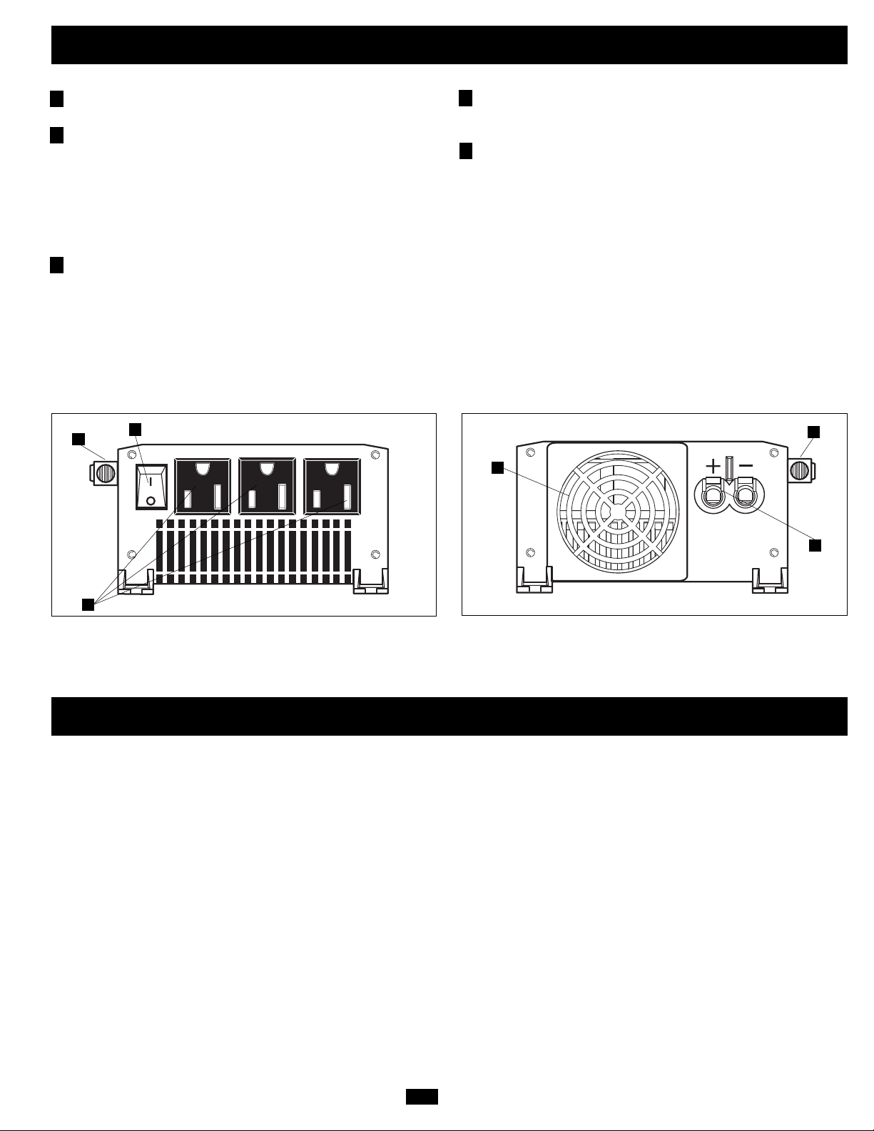
AC Outlets: 3 NEMA 5-15R outlets allow you to connect
equipment that you would normally plug into a utility outlet.
Illuminated ON/OFF Switch: When you set the switch to the
ON position, the Inverter provides AC power by converting DC
power from the connected battery. Set the switch to the OFF
position to shut down the Inverter and conserve the battery's
charge when you are not using connected equipment. Also set
the switch to the OFF position to reset the Inverter if it has shut
down due to low battery or overload. See the Operation section
for more information.
Cooling Fan: This fan regulates the internal temperature of the
Inverter and prolongs service life.
DC Power Terminals: These positive and negative terminals
connect to the battery via user-supplied cabling. See the Battery
Connection section for instructions.
Main Ground Screw: Connect to earth ground or to a vehicle
or boat grounding system in order to properly ground the
Inverter. See the Battery Connection section for instructions.
Low Battery Alarm (not shown): An internal circuit
automatically detects low battery voltage and shuts down the
Inverter to preserve your vehicle's battery. Turn the ON/OFF
switch to the OFF position if the alarm sounds. See the
Operation section for more information.
Overload Alarm (not shown): An internal circuit
automatically detects overload conditions and shuts down the
Inverter as a protective measure. Turn the ON/OFF switch to the
OFF position if the alarm sounds. See the Operation section for
more information.
1
2
3
4
5
Operation
Operating Modes
After mounting and connecting your Inverter according to the
instructions in this manual, use the illuminated ON/OFF switch to
choose the Inverter's operating mode.
ON: When you set the switch to the ON position, the Inverter
provides AC power to connected equipment by converting DC
power from your vehicle's battery.
OFF: Set the switch to the OFF position to shut down the Inverter
completely, preventing it from drawing power from your vehicle's
battery. Also set the switch to the OFF position to reset the Inverter
if it has shut down due to low battery or overload.
Resetting the Inverter
The inverter may shut down and cease supplying AC power under
certain conditions in order to protect itself, the battery and
connected equipment. Follow these instructions to restore normal
operation:
• Low Battery Alarm Reset: If the Inverter has shut down due to
low battery, (1) set the ON/OFF switch to the OFF position,
(2) allow the Inverter to cool, (3) start the vehicle's engine to
recharge the battery, (4) allow the battery to recharge completely
and (5) set the ON/OFF switch to the ON position.
• Overload Alarm Reset: If the Inverter has shut down due to
overload, (1) set the ON/OFF switch to the OFF position,
(2) allow the Inverter to cool, (3) remove the equipment that
caused the overload, (4) confirm that any equipment now
connected does not exceed the rated wattage of the Inverter and
(5) set the ON/OFF switch to the ON position.
2
1
3
4
5
5
Page 4
4
Battery Selection
54 DC Amps × 5 Hrs. Runtime
= 270 Amp-Hours
Match Battery Amp-Hour Capacity to Your Application
Select a battery or system of batteries that will provide your Inverter with proper DC voltage and an adequate amp-hour capacity to power
your application. Even though Tripp Lite Inverters are highly efficient at DC-to-AC inversion, their rated output capacities are limited by the
total amp-hour capacity of connected batteries plus the output of an alternator when one is used.
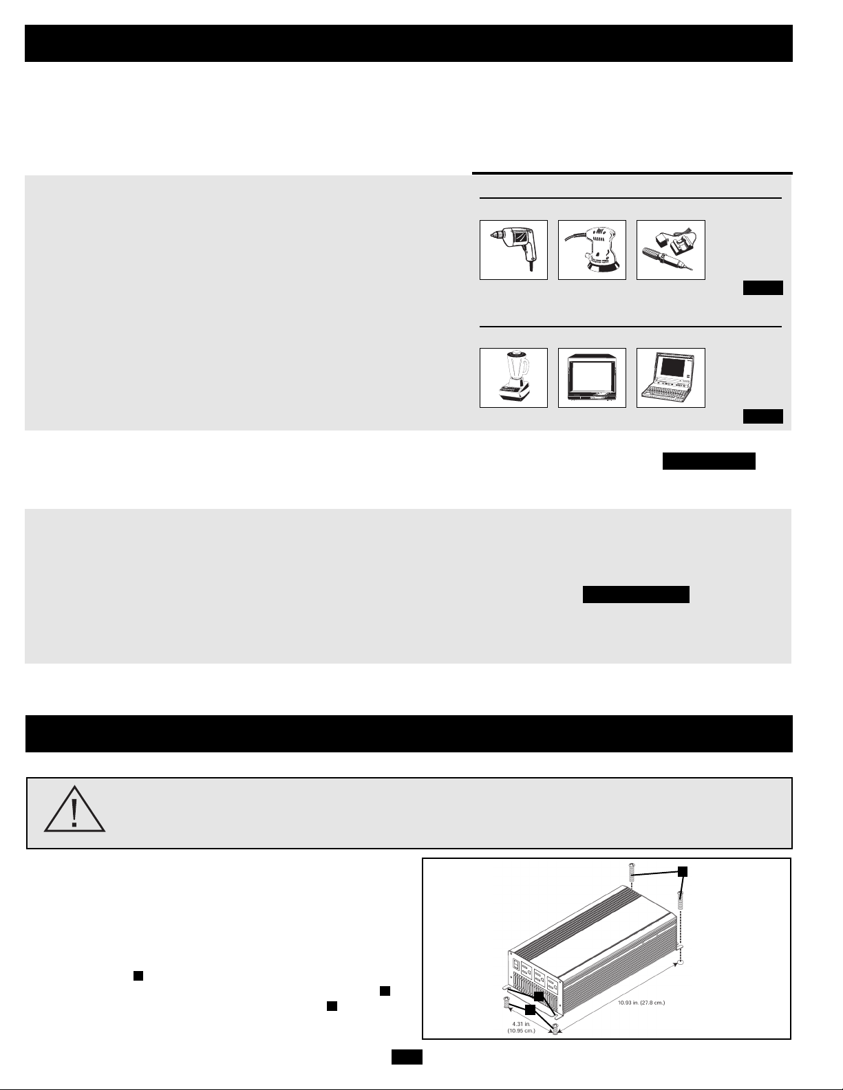
• STEP 1) Determine Total Wattage Required
Add the wattage ratings of all equipment you will connect to your
Inverter. Wattage ratings are usually listed in equipment manuals or on
nameplates. If your equipment is rated in amps, multiply that number times
AC utility voltage to estimate watts. (Example: a drill requires 2.5 amps.
2.5 amps × 120 volts = 300 watts.)
NOTE: Your Inverter will operate at higher efficiencies at about 75% - 80% of nameplate rating.
• STEP 2) Determine DC Battery Amps Required
Divide the total wattage required (from Step 1, above) by the battery voltage
to determine the DC amps required and multiply by 1.2 to account for
conversion losses.
• STEP 3) Estimate Battery Amp-Hours Required
Multiply the DC amps required (from Step 2, above) by the number of hours
you estimate you will operate your equipment exclusively from battery
power before you have to recharge your batteries. This will give you a
rough estimate of how many amp-hours of battery power (from one or
several batteries) you should connect to your Inverter.
NOTE: Battery amp-hour ratings are usually given for a 20-hour discharge rate. Actual amp-hour capacities
are less when batteries are discharged at faster rates. For example, batteries discharged in 55 minutes
provide only 50% of their listed amp-hour ratings, while batteries discharged in 9 minutes provide as little
as 30% of their amp-hour ratings.
Example
Tools
300W + 220W + 20W = 540W
Drill Orbital Sander Cordless Tool Charger
Appliances
300W + 140W + 100W = 540W
Blender Color TV Laptop Computer
Mounting
WARNING! Mount your Inverter BEFORE DC battery connection. Failure to follow
these instructions may lead to personal injury and/or damage to the Inverter and
connected systems.
1
2
3
Tripp Lite recommends that you permanently mount your Inverter
in the configuration illustrated below. The Inverter features integral
mounting brackets on the front and rear of the unit. The user must
supply mounting hardware and is responsible for determining if
hardware and mounting surface are adequate to support the weight
of the unit.
Using the measurements as shown in the diagram install two usersupplied fasteners , leaving the heads slightly raised. Slide the
unit over the fasteners to engage the mounting bracket slots .
Tighten fasteners. Install two additional fasteners over the
remaining mounting bracket.
3
2
1
1.2 x 540 watts ÷ 12V = 54 DC Amps
Page 5
5
Vehicular Applications
Your Inverter’s Nominal DC Input Voltage must match the voltage of your battery or batteries—12 Volts in most vehicular applications.
It is possible to connect your Inverter to the main battery within your vehicle’s electrical system. In many vehicular contexts, the Inverter
will be connected to one or more dedicated auxiliary (house) batteries which are isolated from the drive system to prevent possible draining
of the main battery.
Battery Connection
• Connect DC Wiring: Though your
Inverter is a high-efficiency converter of
electricity, its rated output capacity is
limited by the length and gauge of the
cabling running from the battery to the unit.
Use the shortest length and largest diameter
cabling (maximum 4 AWG or 5 mm) to fit
your Inverter’s DC Input terminals. Shorter
and heavier gauge cabling reduces DC
voltage drop and allows for maximum
transfer of current. Your Inverter is capable
of delivering peak wattage at up to 200% of
its rated continuous wattage output for brief
periods of time. Heavier gauge cabling
should be used when continuously operating
heavy draw equipment under these
conditions. Tighten your Inverter and
battery terminals to approximately 3.5
Newton-meters of torque to create an
efficient connection and to prevent
excessive heating at this connection.
Insufficient tightening of the terminals could
void your warranty. See Specifications for
Recommended Cable Sizing.
• Connect Ground: Using a 12-18 AWG
(1-2 mm) wire, directly connect the Main
Ground Screw to the vehicle’s chassis or
earth ground. See the Feature Identification
section to locate the Main Ground Screw.
All installations must comply with national
and local codes and ordinances.
• Connect Fuse: Tripp Lite recommends
that you connect your Inverter’s positive DC
Terminal directly to a fuse(s) and fuse
block(s) within 45 cm (18 inches) of the
battery. The fuse’s rating must equal or
exceed the Minimum DC Fuse Rating listed
in your Inverter’s specifications. See
Specifications for fuse recommendations.
See diagrams below for proper fuse
placement.
Connect your Inverter to your batteries using the following procedures:
WARNING!
• Failure to properly ground your Inverter to a vehicle’s chassis or earth ground may result in a
lethal electrical shock hazard.
• Never attempt to operate your Inverter by connecting it directly to output from an alternator rather
than a battery or battery bank.
• Observe proper polarity with all DC connections.
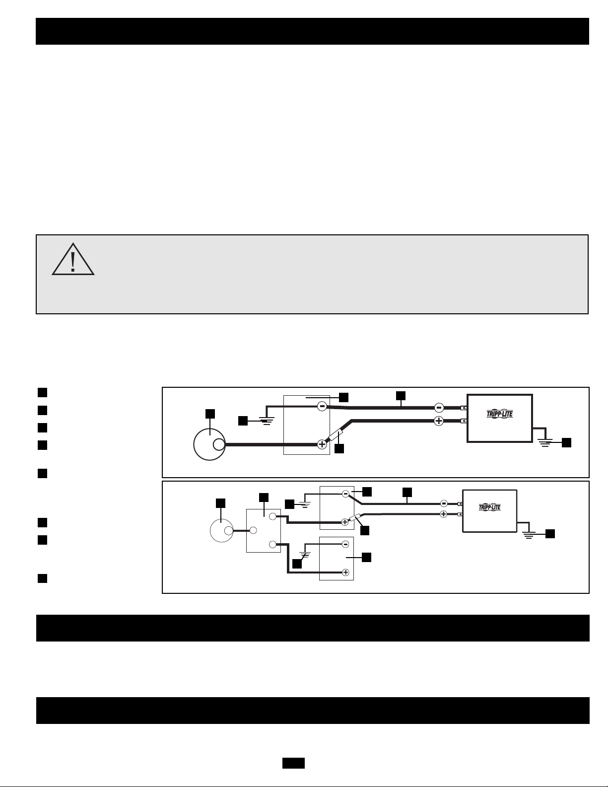
12 Volt Alternator
Vehicle Battery Ground
12 Volt Main Battery
12 Volt Auxiliary (House)
Battery
UL or CE Approved Fuses &
Fuse Blocks (mounted within
18 inches [45 cm] of the
battery)
Battery Isolator
Large Diameter Cabling,
Maximum 4 AWG or 5 mm
to Fit Terminals
12-18 AWG (1-2 mm) Ground
Wire to Vehicle Frame or
Earth Ground
8
7
6
5
4
3
2
1
12 Volt Main Battery Connection—two DC terminals
12 Volt Main and Auxiliary (House) Battery Connection (Isolated Parallel)—two DC terminals
1
2
3
5
7
8
8
7
4
5
3
2
2
1
6
Service
Maintenance
If you are returning your Inverter to Tripp Lite, please pack it carefully, using the ORIGINAL PACKING MATERIAL that came with the
unit. Enclose a letter describing the symptoms of the problem. If the Inverter is within the warranty period, enclose a copy of your sales
receipt. To obtain service you must obtain a Returned Material Authorization (RMA) number from Tripp Lite or an authorized Tripp Lite
service center.
Your Inverter requires no maintenance and contains no user-serviceable or replaceable parts, but should be kept dry at all times. Periodically
check, clean and tighten all cable connections as necessary, both at the unit and at the battery.
12 Volts
12 Volts
12 Volts
12 Volts
12 Volts
12 Volt Inverter
12 Volt Inverter
Page 6

6
Please check the following before sending the Inverter in for service:
Troubleshooting
Model: PV700HF
Output Power (Maximum Continuous Watts)*: 700
Output Power (Peak Watts)**: 1400
Input Voltage (DC): 12V nominal (10-15V)
Output Voltage (AC)/Frequency: 120V / 60 Hz. nominal
Output Waveform: PWM Sine Wave
Low Battery Voltage Alarm (Volts): 10.5V
Low Battery Voltage Shutdown (Volts): 10V
AC Outlets: 3 (NEMA 5-15R)
Circuit Protection (Minimum DC Fuse Rating): 125-amp fuse (external)
Minimum Battery Cable Size: 6 AWG (4 mm)
Maximum Battery Cable Size: 4 AWG (5 mm)
Ground Cable Size: 12-18 AWG (1-2 mm)
Housing Material: Extruded Aluminum
* Maximum output power (continuous or peak) only available when vehicle battery is properly charged. Run vehicle engine
often to maintain proper charge. ** Peak Output Power is instantaneous.
Tripp Lite warrants its Inverters to be free from defects in materials and workmanship for a period of 1 year from the date of initial purchase. Tripp Lite’s obligation under this warranty is limited to repairing or replacing (at its sole option) any such defective
products. To obtain service under this warranty you must obtain a Returned Material Authorization (RMA) number from Tripp Lite or an authorized Tripp Lite service center. Products must be returned to Tripp Lite or an authorized Tripp Lite service center
with transportation charges prepaid and must be accompanied by a brief description of the problem encountered and proof of date and place of purchase.
This warranty does not apply to equipment which has been damaged by accident, negligence or misapplication or has been altered or modified in any way, including opening of the unit’s casing for any reason. This warranty applies only to the original
purchaser who must have properly registered the product within 10 days of purchase.
EXCEPT AS PROVIDED HEREIN, TRIPP LITE MAKES NO WARRANTIES, EXPRESS OR IMPLIED, INCLUDING WARRANTIES OF MERCHANTABILITY AND FITNESS FOR A PARTICULAR PURPOSE. Some states do not permit limitation or exclusion
of implied warranties; therefore, the aforesaid limitation(s) or exclusion(s) may not apply to the purchaser.
EXCEPT AS PROVIDED ABOVE, IN NO EVENT WILL TRIPP LITE BE LIABLE FOR DIRECT, INDIRECT, SPECIAL, INCIDENTAL OR CONSEQUENTIAL DAMAGES ARISING OUT OF THE USE OF THIS PRODUCT, EVEN IF ADVISED OF THE
POSSIBILITY OF SUCH DAMAGE. Specifically, Tripp Lite is not liable for any costs, such as lost profits or revenue, loss of equipment, loss of use of equipment, loss of software, loss of data, costs of substitutes, claims by third parties, or otherwise.
Warranty Registration
Visit www.tripplite.com/warranty today to register the warranty for your new Tripp Lite product. You'll be automatically entered into a drawing for a chance to win a FREE Tripp Lite product!*
* No purchase necessary. Void where prohibited. Some restrictions apply. See website for details.
Regulatory Compliance Identification Numbers
For the purpose of regulatory compliance certifications and identification, your Tripp Lite product has been assigned a unique series number. The series number can be found on the product nameplate label, along with all required approval markings and
information. When requesting compliance information for this product, always refer to the series number. The series number should not be confused with the marking name or model number of the product.
Tripp Lite follows a policy of continuous improvement. Product specifications are subject to change without notice.
Symptom Problem Correction
Alarm sounds. Low battery voltage (<10.5 V). Turn Inverter OFF and run engine to recharge vehicle battery.
Output overload. Turn Inverter OFF and remove overload by unplugging high-wattage devices. Load
should not exceed your Inverter's maximum continuous output power (see Specifications).
Inverter does not turn ON when Automatic Inverter shutdown due to low battery Turn Inverter OFF and run engine to
power switch is turned ON. voltage (<10V). recharge vehicle battery.
Automatic Inverter shutdown due to output overload. Turn Inverter OFF and remove overload by unplugging high-wattage devices. Load
should not exceed your Inverter’s maximum continuous output power (see Specifications).
Blown fuse. Replace fuse with standard automotive fuse of identical amperage (see Specifications).
Inverter is unable to power Battery running low. Low battery voltage reduces Turn Inverter OFF and run engine to recharge vehicle battery.
connected equipment. Inverter power output.
Connected equipment load exceeds Inverter’s Turn Inverter OFF and remove overload by unplugging high-wattage devices. Load
maximum continuous output power. should not exceed your Inverter's maximum continuous output power (see Specifications).
Connected equipment experiences Loose connections. Check and secure all connections.
audio/video distortion.
Audio/video interference. Reposition equipment antennas and Inverter.
Specifications
Limited Warranty and Warranty Registration
Typical Runtimes Before Battery Recharge
Although you can operate your Inverter with your vehicle engine off, best results are
usually attained with the engine running. Since the Inverter converts electrical energy
(and doesn’t produce it), the Inverter’s performance is relative to the condition of
your vehicle’s electrical system (battery, alternator and wiring). If other loads (air
conditioner, heater, lights, etc.) are also using power, you may get less runtime.
With Typical With Typical With Typical
Compact Vehicle Mid-Size Vehicle Full-Size Vehicle
(4 cylinder)
Battery,
(6 cylinder)
Battery,
(8 cylinder)
Battery,
Model: PV700HF Alternator & Wiring Alternator & Wiring Alternator & Wiring
1/2 Load (engine ON) continuous continuous continuous
Full Load* (engine ON) 1-2 hours 2-4 hours continuous
1/2 Load (engine OFF) not recommended 1 hours 2 hours
Full Load* (engine OFF) not recommended not recommended 1 hour
NOTE: You can maximize output power by following one or more of these steps: (1) connect multiple batteries to the
Inverter; (2) keep batteries fully charged by running the vehicle's engine often; (3) install the Inverter as close to the
batteries as possible; (4) connect the heaviest gauge cable possible to the Inverter's DC terminals; (5) use the Inverter in a
vehicle with a heavy-duty alternator; (6) run the vehicle's engine at higher RPMs.
Battery Wiring Recommendations
For maximum efficiency, keep battery wires as short as possible. For very short runs, 6 AWG (4 mm) wiring may be
adequate; for longer runs 4 AWG (5 mm) wiring is recommended. Acceptable output power is directly dependent on wire
length: the shorter the wiring, the better the performance.
Page 7

7
Manual del Propietario
1111 W. 35th Street, Chicago, IL 60609 USA
Soporte a Clientes: (773) 869-1234
www.tripplite.com
Copyright © 2007 Tripp Lite. PowerVerter®es una marca comercial registrada de Tripp Lite. Todos los derechos reservados. Derechos de autor.
Confiable Energía CA Cuando la Necesite
¡Felicidades! Usted ha comprador un Inversor de gran calidad diseñado par funcionar como una fuente de energía móvil alimentado por la
batería de su automóvil. Los Inversores PowerVerter Convierten la energía de 12V CD (de la batería) en energía 120V CA (Casera-Doméstica),
Permitiéndole usar equipo de uso domestico que usa en su casa—computadoras, utensilios eléctricos, equipo electrónico, herramientas eléctricas
y más—mientras viaja en su automóvil o trabajar en ubicaciones remotas que carecen de energía CA. Los inversores PowerVerter incluyen
características avanzadas que protegen su equipo alargando la vida de servicio de su batería y que aseguran que siempre contará con suficiente
energía en la batería de su automóvil para poder arrancarlo nuevamente.
PowerVerter
®
Inversor CD-a-CA
Modelo: PV700HF
Entrada Salida
12V CD 120V, 60Hz CA
Contenido
• Protección Automática contra Sobre Cargas
• Protección Automática contra Batería Baja
• Inversión CD-a-CA de Alto Rendimiento
• Energía de Salida con Frecuencia
Controlada
• Operación Simple, Libre de Mantenimiento
• Construcción Resistente a la Humedad*
• 3 Tomas de Salida de CA
* El Inversor es resistente a la humedad. No es a prueba de agua.
Instrucciones de seguridad importantes
Garantía limitada
Identificación de funciones
Operación
Selección de baterías
Montaje
Conexión de la batería
Servicio/Mantenimiento/Solución de problemas
English
Français
8
13
9
9
10
10
11
12
1
14
Especificaciones
12
Page 8

8
Instrucciones de seguridad importantes
¡CONSERVE ESTAS INSTRUCCIONES!
Este manual contiene instrucciones y advertencias importantes que deben seguirse durante la instalación, operación y almacenamiento de
todos los inversores de Tripp Lite.
Advertencias de ubicación
• Instale su inversor (ya sea para una aplicación móvil o fija) en un lugar o compartimiento que minimice la exposición al calor,
al polvo, a la luz solar directa y a la humedad.
• Aunque su inversor es resistente a la humedad, no es impermeable. Llenar la unidad con agua causará un cortocircuito y podría causar
lesiones personales por una descarga eléctrica. Nunca sumerja la unidad, y evite cuaquier área en donde pueda acumularse agua. El
montaje debe realizarse en la ubicación más seca disponible.
• Deje un espacio de al menos de 5 cm en la parte frontal y posterior del inversor para una adecuada ventilación. A mayor carga de
equipo conectado, la unidad generará más calor. Cualquier compartimiento que contenga al Inversor debe estar adecuadamente
ventilado con suficiente flujo de aire del exterior a fin de evitar sobre calentar el Inversor.
• No instale el inversor directamente cerca de medios de almacenamiento magnético, ya que puede dañar los datos.
• No instale el inversor cerca de materiales inflamables, combustibles o productos químicos.
• No monte esta unidad con el panel frontal o con el panel trasero hacia abajo (Bajo ningún ángulo o inclinación). Si lo monta de
esta manera, inhibirá seriamente el sistema de enfriamiento interno de la unidad; lo que finalmente causará daños al producto
que no están cubiertos por la garantía.
Advertencias de conexión de batería
• Los sistemas de baterías múltiples deben estar conformados por baterías con un voltaje, una antigüedad, una capacidad en ampers
hora y un tipo idénticos.
• Debido a que puede acumularse gas hidrógeno explosivo cerca de las baterías si no están bien ventiladas, no debe instalar baterías (ya
sea para una aplicación móvil o fija) en un área sin circulación de aire. En forma ideal, cualquier area debe tener ventilación al
exterior.
• Pueden producirse chispas durante la conexión final de la batería. Siempre observe la correcta polaridad al conectar las baterías.
• No permita que ningún objeto entre en contacto con las dos terminales de entrada de corriente continua. No ponga en cortocircuito ni
puentee estas terminales. Podrían producirse serias lesiones personales o daños a la propiedad.
• Conecte el Inversor a la batería con los fusibles para CD recomendados. (Vea Conexión de la Batería)
Advertencias Sobre la Conexión a Tierra
• Una operación segura requiere conectar la oreja de tierra principal del Inversor directamente al chasis del automóvil o directamente
a tierra física.
Advertencias sobre la conexión de equipos
El uso de este equipo en aplicaciones de soporte de vida en donde la falla de este equipo pueda razonablemente hacer suponer
que causará fallas en el equipo de soporte de vida o afecte significativamente su seguridad o efectividad, no está recomendado.
No use este equipo en la presencia de una mezcla anestésica inflamable con aire, oxigeno u óxido nitroso.
• Puede experimentar un funcionamiento irregular si conecta un supresor de picos, un regulador de voltaje o un UPS a la salida del
inversor.
Advertencias de operación
• Su inversor no requiere mantenimiento de rutina. No abra el dispositivo por ninguna razón. No hay partes en su interior que
requieran mantenimiento por parte del usuario.
• Mientras la alimentación de baterías y/o la entrada de corriente alterna estén conectadas, hay voltajes potencialmente letales dentro del
inversor. En consecuencia, durante cualquier trabajo de mantenimiento, deben desconectarse la alimentación de las baterías y la
entrada de corriente alterna.
• No conecte ni desconecte las baterías mientras el inversor está operando. Puede producirse un arco voltaico peligroso.
Page 9

9
Identificación de funciones
Operación
Tomas de salida de CA: 3 receptáculos NEMA 5-15R de salida
le permiten conectar equipos que usted normalmente conectaría
en una toma de la red del servicio público.
Interruptor de Encendido y Apagado Iluminado: Cuando
coloca el interruptor en la posición ON [Encendido], el Inversor
entregará energía CA al convertir la energía CD de la batería a
la que está conectado. Coloque el interruptor en la posición OFF
[Apagado] para apagar el Inversor y conservar la carga de la
batería cuando no este usando el equipo conectado. También
coloque el interruptor en la posición OFF [Apagado] para
restaurar el Inversor si este se ha apagado debido a batería baja,
sobre carga o sobre calentamiento. Vea la sección Operación
para mayor información.
Ventilador de Enfriamiento: Este ventilador regula la
temperatura interna del Inversor y prolonga su vida de servicio.
Terminales CD: Estas terminales, positiva y negativa, se
conectan a la batería a través de un cable suministrado por el
usuario. Vea la sección Conexión de la Batería para obtener
instrucciones.
Oreja a Tierra Principal: Conecte esta oreja a tierra física o al
sistema a tierra de un vehículo o bote a fin de conectar
adecuadamente a tierra el Inversor. Vea la sección Conexión de
la Batería para obtener instrucciones.
Alarma de Batería Baja (no se muestra): Un circuito interno
detecta automáticamente el bajo voltaje de una batería y apaga
el Inversor para preservar la batería de su vehículo. Coloque el
interruptor ON/OFF [Encendido/Apagado] en la posición
“OFF” [Apagado] en el caso que sonara la alarma. Vea la
sección Operación para más información.
Alarma de Sobre Carga (no se muestra): Un circuito interno
detecta automáticamente condiciones de sobre carga y apaga el
Inversor como una medida de protección. Coloque el interruptor
ON/OFF [Encendido/Apagado] en la posición “OFF”
[Apagado] si sonara la alarma. Vea la sección Operación para
más información.
1
2
3
4
5
Modos de Operación
Después de montar y conectar el Inversor de acuerdo a las
instrucciones de este manual, use el interruptor iluminado ON/OFF
para seleccionar el modo de operación del Inversor.
ON [Encendido]: Cuando coloca el interruptor en la posición ON
[Encendido], el Inversor entrega energía CA al equipo conectado al
convertir la energía CD de la batería de su vehículo.
OFF [Apagado]: Coloque el interruptor en la posición OFF
[Apagado] para apagar el Inversor completamente, evitando así que
tome energía de la batería de su vehículo. También coloque el
interruptor en la posición OFF [Apagado] para restaurar el Inversor
si se ha apagado debido batería baja, sobre carga o sobre
calentamiento.
Restaurando el Inversor
El Inversor puede apagarse y dejar de entregar energía CA bajo
ciertas condiciones a fin de protegerse a si mismo, la batería y el
equipo conectado. Siga estas instrucciones para restaurarlo a una
operación normal.
• Restaurar la Alarma de Batería Baja: Si el Inversor se ha
apagado debido a batería baja, (1) coloque el interruptor ON/OFF
[Encendido/Apagado] en la posición OFF [Apagado], (2) permita
que el Inversor se enfríe, (3) arranque el motor de su vehículo para
recargar la batería, (4) permita que la batería se recargue
completamente y (5) coloque el interruptor ON/OFF
[Encendido/Apagado] en la posición ON [Encendido].
• Restaurar la Alarma de Sobre Carga: Si el Inversor se ha
apagado debido a una sobre carga, (1) coloque el interruptor
ON/OFF [Encendido/Apagado] en la posición OFF [Apagado],
(2) permita que el Inversor se enfríe, (3) remueva el equipo que
causó la sobre carga, (4) confirme que el equipo que está ahora
conectado no exceda la capacidad de watts determinada para
Inversor y (5) coloque el interruptor ON/OFF
[Encendido/Apagado] en la posición ON [Encendido].
2
1
3
4
5
5
Page 10

10
Selección de batería
Haga coincidir la capacidad en amperios-hora de su batería con su aplicación
Seleccione una batería o sistema de baterías que le proporcionarán a su inversor un voltaje de corriente continua adecuado y una capacidad
en ampers por hora apropiada a la potencia de su aplicación. Aun cuando los inversores de Tripp Lite son muy eficientes en la inversión
de corriente continua a corriente alterna, sus capacidades de salida están limitadas por la capacidad total en ampers por hora de las baterías
conectadas, más la salida de un alternador si es que se utiliza.
• PASO 1) Determine la potencia total requerida
Añada la potencia nominal de todos los equipos que va a conectar a su
inversor. La potencia nominal de un equipo normalmente está indicada en
su manual o en su placa. Si su equipo tiene un valor en ampers,
multiplique ese número por el voltaje en corriente alterna de la red para
calcular los vatios. (Ejemplo: un taladro requiere 2.5 ampers. 2.5 ampers
× 120 volts = 300 watts)
NOTA: Su inversor operará a mayores eficiencias al 75% - 80%, aproximadamente de su valor de placa.
• PASO 2) Determine la corriente (en ampers) de corriente
continua de batería requerida
Divida el número de watts totales requeridos (del Paso 1, arriba) entre el
voltaje de la batería para determinar los ampers de corriente continua y
multiplique por 1.2 para compensar por pérdidas en la conversión.
• PASO 3) Estime los ampers por hora de batería requeridos
Multiplique los ampers de corriente continua requeridos (del Paso 2 de arriba)
por el número de horas que usted estima que operará su equipo
exclusivamente con energía de batería antes de tener que recargar sus baterías.
Esto le dará un estimado grueso de cuantos ampers por hora de energía de
batería (de una o varias baterías) debe conectar a su inversor.
NOTA: La capacidad de ampers por hora de una batería usualmente se da considerando una descarga
de 20 horas. Las capacidades reales de ampers por hora son menores cuando las baterías están
descargando a mayor velocidad. Por ejemplo, baterías descargadas en 55 minutos proporcionan sólo
50% de sus ampers por hora nominales, mientras que las baterías descargadas en 9 minutos
proporcionan apenas 30% de sus ampers por hora nominales..
Ejemplo
Herramientas
300W + 220W + 20W = 540W
Taladro Lijadora circular Cargador inalámbrico
Aparatos
300W + 140W + 100W = 540W
Licuadora TV Color Computadora portátil
1.2 x 540 watts ÷ 12 V = 54 ampers CC
54 amp. CC × 5 horas funcionamiento
Tiempo de respaldo = 270 ampers por hora
Montaje
¡ADVERTENCIA! Monte su inversor ANTES de conectar la batería de corriente
continua. No seguir estas instrucciones puede producir lesiones personales y/o
daños al inversor y a los sistemas conectados.
Tripp Lite recomienda el montaje permanente de su inversor en
cualquiera de las configuraciones ilustradas abajo. El inversor
presenta soportes de montaje integrados en las partes delantera y
posterior de la unidad. El usuario debe suministrar la tornillería de
montaje y es responsable de determinar si la misma y la superficie
de montaje son adecuadas para soportar el peso del inversor.
Usando las medidas del diagrama, instale dos tornillos
suministrados por el usuario , dejando las cabezas ligeramente
levantadas. Deslice la unidad hacia atrás sobre los tornillos para
enganchar las ranuras de montaje moldeadas en la parte inferior
del gabinete del inversor. Instale dos tornillos adicionales sobre
la parte remanente de las ranuras de montaje.
3
2
1
1
2
3
Page 11

11
Conexión de la batería
• Conexión del cableado de corriente
continua: Aunque su inversor es un
convertidor de electricidad de alta
eficiencia, su capacidad de salida está
limitada por la longitud y el calibre del
cableado desde la batería hasta la unidad.
Use la longitud más corta y el calibre de
mayor diámetro del cableado (máximo
calibre 4 AWG o 5 mm) para instalar los
terminales de entrada de corriente continua
de su inversor. Un cable más corto y de
mayor calibre reduce la caída de voltaje de
corriente continua y permite la máxima
transferencia de corriente. Su inversor puede
entregar una potencia máxima hasta de
200% de su salida de potencia permanente
nominal por breves períodos de tiempo.
Debe usarse un mayor calibre de cable
cuando se opere en forma permanente con
equipos de alto consumo bajo estas
condiciones. Apriete los terminales de su
inversor y su batería hasta 3.5 Newton-metro
de torque, aproximadamente, para crear una
buena conexión y evitar su excesivo
calentamiento. Apretar en forma deficiente
las terminales podría anular su garantía. Vea
la Tabla de calibre mínimo de cable
recomendado en Especificaciones.
• Conexión de tierra: Usando un conductor
calibre 12-18 AWG (1-2 mm), conecte
directamente la oreja principal de tierra al
chasis del vehículo o a la toma de tierra. Vea
la sección Identificación de funciones para
ubicar la oreja principal de tierra. Todas las
instalaciones deben cumplir los códigos y
reglamentos locales y nacionales.
• Conexión de fusible: Tripp Lite
recomienda que conecte la terminal de
corriente continua positiva de su inversor
directamente a un fusible o fusibles y
bloques de fusibles dentro de 45 cm (18") de
la batería. La capacidad del fusible debe ser
igual o mayor que la mínima capacidad de
fusible de CC indicada en las
especificaciones de su inversor. Vea la
sección Especificaciones para
recomendaciones sobre fusibles y bloques
de fusibles. Vea los diagramas siguientes
para la correcta colocación de los fusibles.
Conecte su inversor a sus baterías usando los siguientes procedimientos:
¡ADVERTENCIA!
• No poner a tierra correctamente su inversor, conectando al chasis del vehículo o a la tierra del
sistema, puede producir un choque eléctrico letal.
• Nunca trate de operar su inversor conectándolo directamente a la salida de un alternador en
lugar de a una batería o banco de baterías.
• Observe la polaridad correcta con todas las conexiones de corriente continua.
Aplicaciones Vehiculares
El Voltaje Nominal CD de Entrada de su Inversor debe coincidir con el voltaje de su(s) batería(s)—12V en la mayoría de la aplicaciones
vehiculares. Es posible conectar su Inversor a la batería principal del sistema eléctrico de su vehículo. En muchos contextos vehiculares,
el Inversor se conectará a una o más baterías auxiliares (House) dedicadas que están aisladas del sistema de conducción para evitar el
posible agotamiento de la batería principal.
Conexión de la Batería Principal de 12 Volts—dos terminales CD
Conexión de la Batería Principal y Auxiliar (House)de 12 Volts (Paralela Aislada)—dos terminales CD
1
2
3
5
7
8
8
7
4
5
3
2
2
6
1
Alternador de 12 Volts
Tierra de la Batería del
Vehículo
Batería Principal de 12 Volts
Batería Auxiliar (House)
Fusibles y Bloques de
Fusibles aprobados por UL o
CE (Montados dentro de 18
Pulgadas [45 cm] de la
Batería)
Aisladores de la Batería
Cables de Gran Diámetro
(Máximo 4 AWG o 5 mm
para Ajustarse a las
Terminales)
12-18 AWG o 1-2 mm Cable de
Tierra al Bastidor del Vehículo
o Tierra Física.
8
7
6
5
4
3
2
1
Page 12

12
Servicio
Si está devolviendo su inversor a Tripp Lite, por favor, empáquelo cuidadosamente, usando el MATERIAL DE EMPAQUE ORIGINAL
incluido con la unidad. Adjunte una carta describiendo los síntomas del problema. Si el inversor está dentro del período de garantía, adjunte
una copia de su recibo de compra. Para obtener servicio, debe conseguir un número de Autorización de Devolución del Producto (RMA)
de Tripp Lite o de un centro de servicio autorizado de Tripp Lite.
Su inversor no requiere mantenimiento y no contiene partes reemplazables o a las que el usuario pueda dar servicio, pero siempre debe
mantenerse seco. Revise, limpie y apriete periódicamente todas las conexiones de cables según sea necesario, tanto en la unidad como en
la batería.
Por favor, revise lo siguiente antes de enviar el inversor para servicio:
Mantenimiento
Solución de problemas
Modelo: PV700HF
Potencia de salida (Watts máximos en forma continua)*: 700
Potencia de salida (Watts máximos)**: 1400
Voltaje de entrada (corriente continua): 12 V nominales (10-15V)
Voltaje (corriente alterna)/Frecuencia de salida : 120 V/ 60 Hz. nominales
Forma de onda de salida: Onda sinusoidal PWM
Alarma de bajo voltaje de la batería (Volts): 10.5 V
Apagado por bajo voltaje de la batería (Volts): 10 V
Salidas de corriente alterna: 3 (NEMA 5-15R)
Protección de circuito (Clase/tipo mínimo del fusible CD): Fusible de 125 ampers (externo)
Calibre mínimo del cable de la batería: 6 AWG (4 mm)
Calibre máximo del cable de la batería: 4 AWG (5 mm)
Calibre del cable de tierra: 12-18 AWG (1-2 mm)
Material del gabinete: Aluminio moldeado
* Máxima potencia de salida (continua o máxima) sólo disponible cuando la batería del vehículo está adecuadamente
cargado. Haga funcionar el motor del vehículo con frecuencia para mantener la carga adecuada. ** La potencia máxima
de salida es instantánea.
Típicos tiempos de respaldo antes de recargar la batería
Aunque puede operar su inversor con el motor apagado, normalmente se alcanzan
mejores resultados con el motor funcionando. Ya que el inversor convierte energía
eléctrica (no la produce), su rendimiento es relativo a la condición del sistema
eléctrico de su vehículo (batería, alternador y cableado) Si otras cargas (aire
acondicionado, calefacción, luces, etc.) también están usando energía, puede obtener
menor tiempo de respaldo.
Con vehículos Con vehículos Con vehículos
compactos típicos medianos grandes
(4 cilindros) típicos (6 cilindros) típicos (8 cilindros)
Batería, alternador Batería, alternador Batería, alternador
Modelo: PV700HF y cableado y cableado y cableado
1/2 carga continuos continuos continuos
(Motor Encendido/En Marcha)
Carga Completa* 1-2 horas 2-4 horas continuos
(Motor Encendido/En Marcha)
1/2 Carga (Motor Apagado) no recomendado 1 hora 2 horas
Carga Completa* no recomendado no recomendado 1 hora
(Motor Apagado)
NOTA: Puede maximizar la potencia de la salida siguiendo uno o más de estos pasos: (1) conecte varias baterías al
Inversor; (2) mantenga las baterías completamente cargadas arrancando el motor de su vehículo a menudo; (3) instale el
Inversor lo más cerca que sea posible a las baterías; (4) conecte un cable, con el calibre más grueso que sea posible, a
las terminales CD del Inversor; (5) use el Inversor en un vehículo con un alternador de uso pesado; (6) opere el motor del
vehículo a RPM más altas.
Recomendaciones del Cableado de la Batería
Para una eficiencia máxima, mantenga los cables de la batería tan cortos como sea posible. Para corridas cortas un
cableado 6 AWG (4 mm) puede ser adecuado; para corridas más largas se recomienda un cableado 4 AWG (5 mm). Una
salida de potencia aceptable depende directamente de la longitud del cable: Entre más corto el cable mejor será el rendimiento.
Síntoma Problema Corrección
Suena la alarma. Bajo voltaje de la batería (< 10.5 V). Apague el inversor (OFF) y haga funcionar el motor para recargar la batería.
Sobrecarga en la salida. Apague el inversor (OFF) y elimine la sobrecarga desconectando dispositivos de alto
consumo. La carga no debe exceder la máxima potencia de salida ininterrumpida de
su inversor (consulte las especificaciones).
El inversor no enciende cuando se Apagado automático del inversor debido a voltaje Apague el inversor (OFF) y haga funcionar el motor para recargar la batería.
enciende (ON) el interruptor de bajo de la batería (<10V).
alimentación. Apagado automático del inversor debido a Apague el inversor (OFF) y elimine la sobrecarga desconectando dispositivos de alto
sobrecarga. consumo. La carga no debe exceder la máxima potencia de salida ininterrumpida de
su inversor (consulte las especificaciones).
Fusible quemado. Reemplace el fusible con un fusible automotriz estándar de la misma capacidad (consulte
las especificaciones).
El inversor no puede alimentar La batería en operación está con carga baja. Un Apague el inversor (OFF) y haga funcionar el motor para recargar la batería.
al equipo conectado. bajo voltaje de la batería reduce la salida de
potencia del inversor.
La carga del equipo conectado excede la máxima Apague el inversor (OFF) y elimine la sobrecarga desconectando dispositivos de alto
potencia de salida ininterrumpida del inversor. consumo. La carga no debe exceder la máxima potencia de salida ininterrumpida de
su inversor (consulte las especificaciones).
El equipo conectado experimenta Conexiones flojas o sueltas. Revise y asegure todas las conexiones.
distorsión de audio/vídeo. Interferencia de audio/vídeo. Reubique las antenas del equipo y el inversor.
Especificaciones
Page 13

13
Tripp Lite garantiza que sus inversores están libres de defectos en materiales y mano de obra por un período de un año a partir de la fecha de compra. Bajo esta garantía, la obligación de Tripp Lite está limitada a reparar o reemplazar (a su opción) cualquier
producto defectuoso. Para obtener servicio bajo esta garantía, debe conseguir un número de Autorización de devolución de mercadería (RMA) de Tripp Lite o de un centro de servicio autorizado de Tripp Lite. Los productos deben ser devueltos a Tripp Lite
o a un centro de servicio autorizado de Tripp Lite con los cargos de transporte pagados por adelantado y deben estar acompañados de una breve descripción del problema encontrado y un comprobante de la fecha y el lugar de compra.
Esta garantía no se aplica al equipo que ha sido dañado por accidente, negligencia o uso inadecuado, o que ha sido alterado o modificado en cualquier forma, incluyendo la abertura de la caja de la unidad por cualquier motivo. Esta garantía solamente se
aplica al comprador original que debe haber registrado correctamente el producto dentro de los 10 días de la compra.
SALVO POR LO ESTABLECIDO EN ESTE DOCUMENTO, TRIPP LITE NO EXPRESA NINGUNA GARANTÍA, EXPRESA O IMPLÍCITA, INCLUYENDO GARANTÍAS DE COMERCIABILIDAD O IDONEIDAD PARAUN PROPÓSITO PARTICULAR. Algunos
estados no permiten limitaciones o exclusiones de las garantías implícitas; por lo tanto, las limitaciones o exclusiones mencionadas anteriormente pueden no aplicarse al comprador.
SALVO POR LO ESTABLECIDO ARRIBA, EN NINGÚN CASO TRIPP LITE SERÁ RESPONSABLE POR DAÑOS DIRECTOS, INDIRECTOS, ESPECIALES, INCIDENTALES O EMERGENTES, RESULTANTES DEL USO DE ESTE PRODUCTO, AUN EN
EL CASO DE HABERSE INFORMADO DE LA POSIBILIDAD DE DICHOS DAÑOS. Específicamente, Tripp Lite no es responsable por ningún costo, como pérdida de ingresos o beneficios, pérdida de equipos, pérdida de uso de equipos, pérdida de software,
pérdida de datos, costos por reemplazos, reclamaciones de terceras partes, o lo que corresponda.
LEA SU INSTRUCTIVO
CONSULTE SUS CONDICIONES DE GARANTÍA POR PRODUCTO
PÓLIZA DE GARANTÍA
Este equipo marca Tripp Lite, modelo _______________ está garantizado por TRIPP LITE, que tiene su domicilio en la calle de Sierra Candela No.111-107, Col Lomas de Chapultepec, CP 11000, México, DF, y puede hacer efectiva su garantía así como
obtener partes, componentes, consumibles y accesorios en el Centro de Servicio Q PLUS ubicado en Av Coyoacan 931, Col. Del Valle, C.P. 03120 México. D.F., tel. 50 00 27 00 contra cualquier defecto de fabricación y funcionamiento, imperfecciones de
materiales, piezas, componentes y mano de obra al consumidor acorde a la siguiente tabla:
Producto Modelo Vigencia
Sistema de Energía Ininterrumpible (UPS) Familia: BC, OMNI, SMART, SMARTONLINE MONOFASICOS 2 Años
Sistema de Energía Ininterrumpible (UPS) Familia: SMARTONLINE 3PH 1 Año
Regulador y Acondicionador de Tensión Familia: LS, LC 2 Años
Inversores Familia: APS, PV 2 Años
Multiplexor y Conmutador Familia: KVM 5 Años
Conmutador Modelo: B020-016 6 Meses
Supresor de Picos de Tensión Familia: PROTECT IT, ISOBAR 25 Años
CONDICIONES
1. Para hacer válida su garantía no podrán exigirse mayores requisitos que la presentación de esta póliza debidamente llenada y sellada por el establecimiento que lo vendió junto con el producto en el lugar donde fue adquirido.
2. TRIPP LITE, se compromete a reparar, y en caso de que a su juicio no sea posible la reparación, a cambiar el equipo, así como las piezas y componentes defectuosos del mismo sin cargo alguno para el propietario durante el periodo de garantía,
así como los gastos de transportación razonablemente erogados del producto que deriven de su cumplimiento, dentro de su red de servicio.
3. El tiempo de reparación en ningún caso será mayor de 30 días contados a partir de la fecha de recepción del producto en el Centro Autorizado de Servicio, en donde también podrán adquirir refacciones y partes.
4. En caso de que la presente póliza de garantía se extraviara, el consumidor puede recurrir a su proveedor para que expida un duplicado de la póliza de garantía, previa presentación de la nota de compra o factura correspondiente.
EXCLUSIONES
Esta garantía no es válida en los siguientes casos:
a) Cuando el producto se hubiese utilizado en condiciones distintas a la normales.
b) Cuando el producto no hubiese sido operado de acuerdo con el instructivo de uso que se le acompaña.
c) Cuando el producto hubiese sido alterado o reparado por personas no autorizadas por el fabricante nacional, importador o comercializador responsable respectivo.
Este equipo fue vendido por: _____________________________________
con domicilio en ________________________________________________
el día _____ de ___________ de ________, fecha a partir de la que inicia la presente garantía.
Cumplimiento de las normas de los números de identificación
Para fines de identificación y certificación del cumplimiento de las normas, su producto Tripp Lite tiene asignado un número de serie único. Puede encontrar el número de serie en la etiqueta de la placa de identificación del producto, junto con los símbolos
de aprobación e información requeridos. Al solicitar información sobre el cumplimiento de las normas para este producto, siempre mencione el número de serie. El número de serie no debe ser confundido con el nombre de identificación ni con el número
de modelo del producto.
Tripp Lite tiene una política de mejoramiento continuo. Las especificaciones están sujetas a cambio sin previo aviso.
Garantía limitada
Page 14

14
Manuel du propriétaire
1111 W. 35th Street, Chicago, IL 60609 USA
Service à la clientèle : (773) 869-1234
www.tripplite.com
Copyright © 2007 Tripp Lite. PowerVerter®est une marque de commerce enregistrée de Tripp Lite. Tous droits réservés.
Du courant alternatif fiable là où vous en avez besoin
Félicitations ! Vous avez acheté un convertisseur de qualité supérieure conçu pour fonctionner comme source d'énergie mobile alimenté par votre
batterie d'automobile. Les convertisseurs PowerVerter transforme le courant 12 v CC (batterie) en courant 120 v CA (domestique) vous
permettant de vous servir d'appareils couramment utilisés à la maison - ordinateurs, appareils ménagers et électroniques, outils électriques et
autres - lorsque vous voyagez en voiture ou que vous travaillez dans les lieux éloignés qui manquent de courant CA. Les convertisseurs
PowerVerter comprennent des caractéristiques perfectionnées qui protègent votre équipement, prolongent la durée de service de votre batterie
et garantissent que vous aurez toujours assez de puissance de batterie pour démarrer votre véhicule :
PowerVerter
®
Convertisseur CC-CA
Modèle : PV700HF
Entrée Sortie
12 v CC 120 v, 60 Hz CA
Table des matières
• Protection automatique contre les
surcharges
• Protection automatique en cas de
batterie faible
• Conversion CC-CA haute -performance
• Puissance de sortie “ commandée
par fréquence ”
• Fonctionnement simple, sans entretien
• Construction résistant à l'humidité *
• 3 Prises de sortie CA
* Le convertisseur résiste à l'humidité mais n'est pas étanche.
Importantes consignes de sécurité
Garantie limitée
Identification de caractéristiques
Fonctionnement
Choix de batterie
Montage
Branchement des batteries
Réparation/Entretien/Dépannage
English
Español
15
20
16
16
17
17
18
19
1
7
Spécifications
19
Page 15

15
Importantes consignes de sécurité
CONSERVER CES DIRECTIVES
Ce manuel contient des directives importantes et des mises en garde que vous devrez respecter durant l'installation, l'utilisation et
l'entreposage de tous les onduleurs Tripp Lite.
Mise en garde concernant l'emplacement
• Installer votre onduleur (pour une application mobile ou stationnaire) à un emplacement ou dans un compartiment où l'exposition à la
chaleur, à la poussière, à la lumière directe du soleil et à l'humidité est réduite.
• Bien que votre onduleur soit résistant à l'humidité, il n'est pas étanche. Noyer l'unité déclenchera un court-circuit et peut entraîner des
blessures corporelles dues à un choc électrique. Ne jamais immerger l'unité et éviter toute zone où pourrait s'accumuler de l'eau
stagnante. Le montage doit se faire à l'emplacement le plus sec possible.
• Maintenir un dégagement minimal de 5 cm à l'avant et à l'arrière de l'onduleur pour garantir une bonne circulation d'air. Plus la charge
de l'équipement branché est lourde, plus l'unité générera de chaleur. Tout compartiment contenant le convertisseur doit être aéré par
une circulation d'air extérieur pour empêcher la surchauffe de celui-ci.
• Ne pas installer l'onduleur près de support magnétique de mémoire, une corruption des données pourrait en résulter.
• Ne pas installer près de matériaux inflammables, de combustible ou de produits chimiques.
• Ne pas monter l'unité avec son panneau avant ou arrière à l'envers (quelque soit l'angle). Monter de cette façon va entraver
sérieusement le refroidissement interne de l'unité, provoquant des dégâts non couverts par la garantie.
Mises en garde au sujet du connexion de batterie
• Les tension, âge, puissance en ampères/heure et type des batteries de système de batteries multiples doivent être identiques.
• À cause de la possibilité d'accumulation d'hydrogène explosif près des batteries si elles ne sont pas bien ventilées, il ne faut pas
installer vos batteries (que ce soit pour une application mobile ou stationaire) dans un compartiment sans circulation d'air. Idéalement,
tout compartiment devrait disposer d'une ventilation d'air extérieur.
• Des étincelles peuvent avoir lieu durant le branchement final de la batterie. Observer toujours la bonne polarité quand vous branchez
les batteries.
• Ne pas laisser d'objets en contact avec les deux bornes d'entrée CC. Ne pas établir de court circuit ou de pont entre ces bornes. Cela
pourrait entraîner des blessures corporelles sérieuses et des dommages matériels.
• Connecter le convertisseur à la batterie avec un fusible CC (voir Connexion de la batterie) recommandé.
Mises en garde relatives aux connexions de terre
• Afin qu'il fonctionne en toute sécurité, il faut connecter la cosse de mise à la terre du convertisseur directement au châssis du véhicule
ou à une prise de terre.
Mises en garde relatives aux connexions de l'équipement
Il est déconseillé d'utiliser cet équipement dans des applications médicales où une panne de cet équipement pourrait
normalement provoquer la panne de l'équipement de survie ou altérer notablement sa sécurité ou son efficacité. Ne pas utiliser
cet équipement en présence d'un mélange anesthétique inflammable avec de l'air, de l'oxygène ou de l'oxyde nitreux.
• Vous pourriez constater une performance inégale si vous branchez un éliminateur de surtension, un régulateur de tension ou un
système UPS à la sortie de l'onduleur.
Mises en garde : Fonctionnement
• Votre onduleur ne nécessite pas d'entretien de routine. Ne jamais ouvrir l'appareil quelle qu'en soit la raison. Aucune pièce interne ne
peut être réparée par l'utilisateur.
• Des tensions mortelles existent potentiellement dans l'onduleur tant que le bloc d'alimentation par batterie ou l'entrée CA sont
branchés. Pendant toute réparation, l'alimentation par batterie et l'entrée CA doivent être débranchées.
• Ne pas brancher ou débrancher les batteries pendant le fonctionnement de l'onduleur qu'il soit en mode de conversion ou de
charge. Le commutateur de mode de fonctionnement devra être dans la position OFF (fermé). Il pourrait s'ensuivre une décharge
disruptive dangereuse.
Page 16

16
Identification de caractéristiques
Prises de sortie CA: 3 prises de sortie NEMA 5-15R vous
permettent de brancher l'équipement que vous brancheriez
normalement dans une prise de courant.
Interrupteur lumineux ON/OFF (marche/arrêt) : Quand
vous mettez l'interrupteur en position ON, le convertisseur
fournit du courant alternatif en transformant le courant continu
de la batterie connectée. Mettre l'interrupteur en position OFF
pour arrêter le convertisseur et conserver la charge de la batterie
lorsque l'équipement connecté n'est pas utilisé. Mettre
également l'interrupteur en position OFF pour réenclencher le
convertisseur s'il s'est arrêté pour cause de batterie faible, de
surcharge ou de surchauffe. Voir la section Fonctionnement
pour plus de renseignements.
Ventilateur de refroidissement : Ce ventilateur permet
d'ajuster la température interne du convertisseur et prolonge sa
durée de vie.
Bornes CC : Ces bornes positives et négatives se connectent à
la batterie à l'aide de câbles fournis par l'utilisateur. Voir la
section Connexion de la batterie pour des instructions.
Cosse principale de mise à la terre : Connecter cette cosse à
une prise de terre ou à la mise à la masse d'un véhicule ou d'un
bateau afin de bien connecter le convertisseur à la terre. Voir la
section Connexion de la batterie pour des instructions.
Alarme de batterie faible (non montrée) : Un circuit interne
détecte automatiquement une tension faible de la batterie de
votre véhicule et arrête le convertisseur pour la protéger. Mettre
l'interrupteur ON/OFF en position OFF si l'alarme retentit. Voir
la section Fonctionnement pour plus de renseignements.
Alarme de surcharge (non montrée) : Un circuit interne
détecte automatiquement des conditions de surcharge et arrête
le convertisseur par mesure de protection. Mettre l'interrupteur
ON/OFF en position OFF si l'alarme retentit. Voir la section
Fonctionnement pour plus de renseignements.
1
2
3
4
5
Fonctionnement
Modes de fonctionnement
Après avoir installé et connecté votre convertisseur selon les
instructions de ce manuel, utiliser l'interrupteur ON/OFF lumineux
pour choisir son mode de fonctionnement.
ON (marche) : Quand vous mettez l'interrupteur en position ON, le
convertisseur fournit du courant alternatif en transformant le courant
continu de la batterie connectée de votre véhicule.
OFF (arrêt) : Mettre l'interrupteur en position OFF pour arrêter
complètement le convertisseur, l'empêchant ainsi de vider la batterie
de votre véhicule. Mettre également l'interrupteur en position OFF
pour réenclencher le convertisseur s'il s'est arrêté pour cause de
batterie faible, de surcharge ou de surchauffe.
Réenclencher le convertisseur
Le convertisseur peut s'arrêter et cesser de fournir du courant CA
dans certaines conditions afin de se protéger ainsi que la batterie et
l'équipement connecté. Suivre ces consignes pour restaurer un
fonctionnement normal :
• Réenclenchement de l'alarme de batterie faible : Si le
convertisseur s'est arrêté à cause d'une batterie faible, (1) mettre
l'interrupteur ON/OFF en position OFF, (2) laisser le
convertisseur refroidir, (3) démarrer le moteur du véhicule pour
recharger la batterie, (4) laisser la batterie se recharger
complètement et (5) mettre l'interrupteur ON/OFF en position ON.
• Réenclenchement de l'alarme de surcharge : Si le convertisseur
s'est arrêté à cause d'une surcharge, (1) mettre l'interrupteur
ON/OFF en position OFF, (2) laisser le convertisseur refroidir,
(3) retirer l'équipement qui a causé la surcharge, (4) confirmer que
l'équipement alors connecté ne dépasse pas la puissance nominale
du convertisseur et (5) mettre l'interrupteur ON/OFF en position
ON.
2
1
3
4
5
5
Page 17

17
Choix de batterie
Correspondance de la puissance en Ah de la batterie pour votre application
Choisir une batterie ou un système de batteries qui fournira à votre onduleur une tension CC appropriée et une puissance en Ah suffisante
pour alimenter votre application. Même si les onduleurs sont hautement efficaces pour la conversion du CC au CA, leur puissance nominale
de sortie est limitée par la puissance totale en Ah des batteries branchées et la sortie de l'alternateur si vous en utilisez un.
• ÉTAPE 1) Établissement de la puissance totale requise
Additionner les puissances nominales de tout l'équipement branché à
votre onduleur. Les puissances nominales sont généralement indiquées
dans les manuels d'équipement ou sur les plaques signalétiques. Si votre
équipement est indiqué en ampères, multiplier le nombre d'ampères par la
tension du courant CA pour calculer la puissance en watts. (Exemple :
Une perceuse a besoin de 2,5 A. 2,5 A x 120 volts = 300 watts .)
REMARQUE : Votre onduleur fonctionnera plus efficacement entre 75 % et 80 % de la puissance
indiquée sur la plaque signalétique.
• ÉTAPE 2) Établissement de l'intensité requise en CC de la batterie
Diviser la puissance totale requise le wattage total requis (d'après l'étape
1, ci-dessus) par la tension de la batterie pour déterminer l'intensité
requise en CC et multiplier par 1,2 pour tenir compte des pertes de
conversion.
• ÉTAPE 3) Estimation de la puissance requise en Ah de la batterie
Multiplier l'intensité requise en CC (d'après l'étape 2, ci-dessus) par le nombre
estimé d'heures de fonctionnement de votre équipement alimenté
exclusivement par batterie avant que vous ne deviez recharger vos batteries.
Cela vous donnera une estimation grossière de la puissance de batterie en Ah
(d'une ou de plusieurs batteries) que vous devrez brancher à votre onduleur.
REMARQUE : La puissance nominale en Ah des batteries est habituellement donnée pour un régime de
décharge de 20 h. Les puissances réelles en Ah sont moindres quand les batteries se déchargent à un régime
plus rapide. Par exemple, des batteries déchargées en 55 minutes fournissent seulement 50 % de leur puissance
nominale en Ah, tandis que les batteries déchargées en 9 minutes ne fournissent que 30 % de leur puissance
nominale en Ah.
Exemple
Outils
300W + 220W + 20W = 540W
Perçeuse Ponceuse orbitale Chargeur d'outil sans fil
Appareils
300W + 140W + 100W = 540W
Mélangeur TV couleur Ordinateur portable
1,2 x 540 watts ÷ 12 V = 54 A CC
54 A CC x 5 h. (durée)
= 270 Ah
Montage
MISE EN GARDE ! Monter votre onduleur AVANT de brancher la batterie CC.
Omettre de suivre ces directives pourrait entraîner des blessures corporelles
et/ou des dommages à l'onduleur et aux systèmes branchés.
Tripp Lite vous recommande de fixer votre convertisseur de façon
permanente dans la configuration illustrée ci-dessous. Le
convertisseur dispose de supports de fixation intégrés à l'avant et à
l'arrière de l'appareil. L'utilisateur doit fournir la quincaillerie de
fixation et doit décider lui-même si la quincaillerie et la surface de
fixation peuvent supporter le poids de l'appareil.
À l'aide des mesures indiquées dans le schéma, poser deux attaches
, fournies par l'utilisateur, en laissant les têtes dépasser
légèrement. Faire glisser l'appareil sur les attaches pour engager les
fentes des supports de fixation . Serrer les attaches. Poser deux
autres attaches au support de fixation restant.
3
2
1
1
2
3
Page 18

18
Branchement des batteries
• Branchement du câblage CC : Puisque
votre onduleur est un convertisseur
hautement efficace d'électricité, sa
puissance nominale de sortie est limitée par
la longueur et le calibre des connecteurs CC
du câblage reliant la batterie à l'unité.
Utiliser le câblage le plus court et du plus
gros diamètre (maximum calibre 4 AWG ou
5 mm) pour fixer aux bornes d'entrée CC de
votre onduleur. Un câblage plus court et de
plus gros calibre réduit la baisse de tension
CC et permet un transfert maximal de
courant. Votre onduleur est capable de
délivrer une puissance de pointe jusqu'à 200
% de sa puissance nominale de sortie
continu pour de brèves périodes. Il faut
utiliser un calibre plus gros quand un
équipement qui consomme beaucoup
fonctionne continuellement dans ces
conditions. Serrer vos bornes d'onduleur et
de batterie à environ 3,5 Newton/mètre de
couple pour créer une connexion efficace et
empêcher un réchauffement excessif à cette
connexion. Un serrage insuffisant des
bornes peut annuler votre garantie. Voir la
Spécifications pour le tableau des calibres
minimaux de câble recommandés.
• Branchement de mise à la terre : À l'aide
d'un fil de calibre (12-18 AWG ou 1-2 mm),
connecter la cosse principale de mise à la
terre au châssis du véhicule ou à la terre.
Voir la section Identification des
caractéristiques pour localiser la cosse
principale de mise à la terre. Toutes les
installations doivent être conformes aux
codes et règlements locaux.
• Connexion de fusible : Tripp Lite
recommande que vous connectiez la borne
CC positive de votre onduleur directement à
des fusibles et des blocs de fusibles à moins
de 450 mm (18 po) de la batterie. Le calibre
nominal du fusible doit être égal ou
supérieur au calibre minimal de fusible CC
inscrit dans les spécifications. Voir les
spécifications pour les recommandations de
fusible et de bloc-fusible. Voir les schémas
ci-dessous pour l'emplacement correct des
fusibles.
Branchement de votre onduleur à vos batteries selon les procédures suivantes :
MISE EN GARDE !
• Ne pas mettre à la terre votre onduleur au châssis du véhicule ou au sol peut entraîner un
risque de choc électrique mortel.
• Ne jamais essayer de faire fonctionner votre onduleur en le connectant directement à la sortie
d'un alternateur plutôt qu'à une batterie ou un groupe de batterie.
• Observer la bonne polarité avec toutes les connexions CC.
Applications véhiculaires
La tension nominale d'entrée CC de votre convertisseur doit correspondre à celle de vos batteries—12 V dans la plupart des applications
véhiculaires. Vous pouvez connecter votre convertisseur à la batterie principal à l'intérieur du système électrique de votre véhicule. Dans
de nombreux contextes véhiculaires, le convertisseur sera connecté à une ou plusieurs batteries dédiées auxiliaires (maison) qui sont isolées
du système d'entraînement pour empêcher que la batterie principale se vide.
Connexion de batterie principale 12 volts—deux bornes CC
Connexion (parallèle isolée) de batterie principale et auxiliaire 12 volts (maison)—deux bornes CC
1
2
3
5
7
8
1
6
2
2
4
7
3
5
8
Alternateur 12 volts
Mise à la masse de la batterie
du véhicule
Batterie principale 12 volts
Batterie auxiliaire 12 volts
(Maison)
Fusibles ou boîte à fusibles
homologués UL- ou CE
(Installé à moins de 45 cm
[18 po] de la batterie)
Isolateur de batterie
Câblage de gros calibre
(Maximum 4 AWG ou 5 mm
pour s'adapter aux bornes)
12-18 AWG ou 1-2 mm Fil de
mise à la terre au châssis du
véhicule ou à une prise de terre
8
7
6
5
4
3
2
1
Page 19

19
Réparation
Si vous renvoyez votre onduleur à Tripp Lite, veuillez l'emballer soigneusement dans son EMBALLAGE D'ORIGINE. Joindre une lettre
décrivant les symptômes du problème. Si l'onduleur est encore sous garantie, joindre une copie de votre facture. Pour faire faire une
réparation, vous devrez obtenir un numéro d'autorisation de retour de matériel (RMA) de TRIPP LITE ou d'un centre de service autorisé
TRIPP LITE.
Entretien
Dépannage
Votre onduleur ne requiert aucun entretien et ne contient aucune pièce réparable ou remplaçable par l'utilisateur, mais il doit être maintenu
au sec en tout temps. Vérifier périodiquement, nettoyer et reserrer toutes les connexions de câble, si nécessaire, à la fois de l'unité et de la
batterie.
Modèle : PV700HF
Puissance de sortie (puissance maximale continue)* : 700
Puissance de sortie (puissance maximale)** : 1400
Tension d’entrée (c.c.) : 12 V nominale (10 à 15 V)
Tension de sortie (c.a.)/Fréquence : 120 V / 60 Hz. nominale
Onde de sortie : Onde sinusoïdale (modulation d’impulsions en durée)
Alarme de tension basse de la batterie (V) : 10,5 V
Arrêt de tension basse de la batterie (V) : 10 V
Prises c.a. : 3 (NEMA 5-15R)
Protection de circuit (Calibre minimal du fusible CC) : Fusible 125 A (externe)
Calibre minimal du câble de la batterie : 6 AWG (4 mm)
Calibre maximal du câble de la batterie : 4 AWG (5 mm)
Calibre du câble de mise à la terre : 12-18 AWG (1-2 mm)
Matériau du boîtier : Aluminium extrudé
* La puissance de sortie maximale (continue ou maximale) n’est disponible que lorsque la batterie du véhicule est
correctement chargée. Faire marche le moteur du véhicule pour maintenir une charge appropriée. ** Puissance de sortie
maximale instantanée.
Temps d’exploitation type avant le rechargement la batterie
Bien que l’onduleur puisse fonctionne avec le moteur du véhicule à l’arrêt, de
meilleurs résultats sont obtenus avec le moteur en marche. Dans la mesure où
l’onduleur convertit l’énergie électrique (mais ne la produit pas), sa performance
dépend de l’état du circuit électrique du véhicule (batterie, alternateur et câblage).
Si d’autres charges (climatisation, chauffage, éclairage, etc.) consomment
simultanément de la puissance et la durée d’exploitation peut être réduite.
Avec batterie, Avec batterie, Avec batterie,
alternateur et câblage alternateur et câblage alternateur et
de véhicule compact de véhicule de taille câblage de gros
Modèle : PV700HF type (4 cyl) intermédiaire type (6 cyl) véhicule type (8 cyl)
1/2 charge continu continu continu
(moteur en marche)
Pleine charge* 1-2 heures 2-4 heures continu
(moteur en marche)
1/2 charge (moteur à l'arrêt) non recommandé 1 heure 2 heures
Pleine charge* non recommandé non recommandé 1 heure
(moteur à l'arrêt)
NOTE : Vous pouvez maximiser la puissance de sortie en suivant une ou plus de ces étapes: (1) connecter plusieurs
batteries au convertisseur; (2) garder les batteries à pleine charge en faisant souvent tourner le moteur du véhicule; (3)
installer le convertisseur aussi près que possible des batteries; (4) connecter le câble du plus gros calibre possible aux
bornes CC du convertisseur; (5) utiliser le convertisseur dans un véhicule équipé d'un alternateur haute capacité; (6) faire
tourner le moteur du véhicule à un régime plus élevé.
Recommandations pour le câblage de la batterie
Pour une efficacité maximale, tenir les câbles de batterie aussi courts que possible. Pour des câbles très courts, un
calibre de 6 AWG (4 mm) peut être adéquat; pour des câbles plus longs, un calibre de 4 AWG (5 mm) est recommandé.
La puissance de sortie est directement dépendante de la longueur des câbles : Plus court est le câblage, meilleur est la
performance.
Symptôme Problème Solution
L’alarme retentit. Tension basse de la batterie (<10,5 V). Mettre l’onduleur hors tension et faire marcher le moteur pour recharge la batterie.
Surcharge de sortie. Mettre l’onduleur hors tension et réduire la charge en débranchant les appareils absorbant
beaucoup de puissance. La charge ne doit pas dépasser la puissance maximale continue
de l’onduleur (voir les spécifications).
L’onduleur ne se met pas en marche Arrêt automatique de l’onduleur, tension basse de Mettre l’onduleur hors tension et faire marcher le moteur pour recharge la batterie.
bien que le contact soit sur marche. la batterie (<10 V).
Arrêt automatique de l’onduleur suite à une Mettre l’onduleur hors tension et réduire la charge en débranchant les appareils absorbant
surcharge de sortie beaucoup de puissance. La charge ne doit pas dépasser lapuissance maximale continue
de l’onduleur (voir les spécifications).
Fusible sauté. Remplacer les fusibles par des fusibles standard pour véhicule d’un ampérage équivalent
(voir les spécifications).
L’onduleur n’alimente pas La batterie est faible. Une batterie faible réduit la Mettre l’onduleur hors tension et faire marcher le moteur pour recharge la batterie.
l’équipement branché. puissance de sortie de l’onduleur.
La charge de l’équipement branché dépasse la Mettre l’onduleur hors tension et réduire la charge en débranchant les appareils absorbant
puissance maximale continue de l’onduleur. beaucoup de puissance. La charge ne doit pas dépasser la puissance maximale continue
de l’onduleur (voir les spécifications).
L’équipement branché subit des Connexions desserrées. Vérifier et resserrer les connexions.
distorsions du signal audio/vidéo.
Interférence audio/vidéo. Repositionner les antennes d’équipement et l’onduleur.
Spécifications
Prière de contrôler les éléments suivants avant de renvoyer l’onduleur pour le faire réparer :
Page 20

20
Tripp Lite garantit que cet onduleur est exempt de défauts matériels et de fabrication pendant une (1) année à compter de la date d’achat initiale. En vertu de la présente garantie, la responsabilité de Tripp Lite est limitée à réparer ou à remplacer (la décision
nous appartenant) tout produit défectueux. Pour faire réparer le produit sous garantie, obtenir un numéro d’autorisation de retour d’article (RMA) auprès de Tripp Lite ou d’un centre de service agréé Tripp Lite. Les produits doivent être renvoyés à Tripp Lite
ou à un centre de service agréé Tripp Lite avec frais d’expédition oréréglés et doivent être accompagnés d’une description succincte du problème et de la preuve de la date et du lieu d’achat.
Cette garantie ne couvre pas les produits qui auraient été endommagés par accident, négligence ou mauvaise application ou qui auraient été altérés ou modifiés d’une façon quelconque, y compris l’ouverture du boîtier de l’onduleur. Cette garantie ne couvre
que l’acheteur initial qui doit avoir enregistré le produit dans les dix (10) jours de l’achat.
SAUF CONTRE INDICATION STIPULÉE DANS LA PRÉSENTE, TRIPP LITE N’OFFRE AUCUNE AUTRE GARANTIE, QU’ELLE SOIT EXPRESSE OU IMPLICITE, Y COMPRIS LES GARANTIES DE QUALITÉ MARCHANDE OU D’ADAPTATION À UNE
APPLICATION PARTICULIÈRE. Certaines provinces ou états ne reconnaissent ni l’exclusion ni la limite des garanties implicites ; les limites ou les exclusions susmentionnées peuvent ne pas concerner l’acheteur.
SAUF SI INDIQUÉS CI-DESSUS, TRIPP LITE NE PEUT EN AUCUN CAS ÊTRE TENU RESPONSABLE DES DOMMAGES DIRECTS, INDIRECTS, SPÉCIAUX, INDIRECTS OU ACCESSOIRES QUI DÉCOULERAIENT DE L’UTILISATION DE CE
PRODUIT, ET CELA M ME SI L’UTILISATEUR A ÉTÉ AVERTI DE L’ÉVENTUALITÉ DESDITS DOMMAGES. Plus particulièrement, Tripp Lite ne peut être tenu responsable des frais, tels que les pertes de bénéfices ou de revenus, la perte de l’utilisation de
l’équipement, de logiciel, de données, des frais engagés pour des solutions alternatives, des réclamations de parties tierces ou autres.
Numéros d'identification de conformité aux règlements
À des fins de certification et d'identification de conformité aux règlements, votre produit Tripp Lite a reçu un numéro de série unique. Ce numéro se retrouve sur la plaque signalétique du produit, avec les inscriptions et informations d'approbation requises.
Lors d'une demande d'information de conformité pour ce produit, utilisez toujours le numéro de série. Il ne doit pas être confondu avec le nom de la marque ou le numéro de modèle du produit.
La politique de Tripp Lite est celle d'une amélioration continuelle. Les spécifications peuvent être modifiées sans préavis.
Garantie limitée
200707096 93-2656
1111 W. 35th Street, Chicago, IL 60609 USA
Customer Support: (773) 869-1234
www.tripplite.com
 Loading...