

Page 1

Owner’s Manual
1111 W. 35th Street Chicago, IL 60609 USA
Customer Support: (773) 869-1234 • www.tripplite.com
Important Safety Instructions
2
Installation
3
Basic Operation
6
Battery Replacement
12
Storage and Service
14
SmartOnline
™
Rack/Tower Mount Online UPS Systems
Specifications
14
Español
Français
33
17
Copyright ©2002 Tripp Lite. All rights reserved. SmartOnline™ is a trademark of Tripp Lite.
Troubleshooting
10
Page 2

UPS Location Warnings
• Install your UPS indoors, away from excess moisture or heat, conductive contaminants,
dust or direct sunlight.
• For best performance, keep the indoor temperature between between 32º F and 104º F
(0º C and 40º C).
• Leave adequate space around all sides of the UPS for proper ventilation.
UPS Connection Warnings
• Connect your UPS directly to a properly grounded AC power outlet. Do not plug the
UPS into itself; this will damage the UPS.
• Do not modify the UPS's plug, and do not use an adapter that would eliminate the UPS’s
ground connection.
• Do not use extension cords to connect the UPS to an AC outlet. Your warranty will be
voided if anything other than Tripp Lite surge suppressors are used to connect your UPS
to an outlet.
• If the UPS receives power from a motor-powered AC generator, the generator must
provide clean, filtered, computer-grade output.
Equipment Connection Warnings
• Do not use Tripp Lite UPS Systems for life support applications in which a malfunction
or failure of a Tripp Lite UPS System could cause failure or significantly alter the
performance of a life-support device.
• Do not connect surge suppressors or extension cords to the output of your UPS. This
might damage the UPS and will void the surge suppressor and UPS warranties.
Battery Warnings
• Your UPS does not require routine maintenance. Do not open your UPS for any reason
except battery replacement. There are no user-serviceable parts inside.
• Battery replacement must be performed by qualified service personnel. Because the
batteries present a risk of electrical shock and burn from high short-circuit current,
observe proper precautions. Unplug and turn off the UPS before performing battery
replacement. Use tools with insulated handles, and replace the existing batteries with the
same number and type of new batteries (Sealed Lead-Acid). Do not open the batteries.
Do not short or bridge the battery terminals with any object.
• The UPS batteries are recyclable. Refer to local codes for disposal requirements, or in
the USA only call 1-800-SAV-LEAD for recycling information. Do not dispose of the
batteries in a fire.
• Only connect Tripp Lite battery packs of the appropriate type and correct voltage to the
external battery connector.
• Do not connect or disconnect external batteries while the UPS is operating from battery.
• Do not operate your UPS without batteries.
SAVE THESE INSTRUCTIONS
This manual contains instructions and warnings that should be followed during the
installation, operation and storage of all Tripp Lite UPS Systems. Failure to heed these
warnings will void your warranty.
2
Important Safety Instructions
Page 3
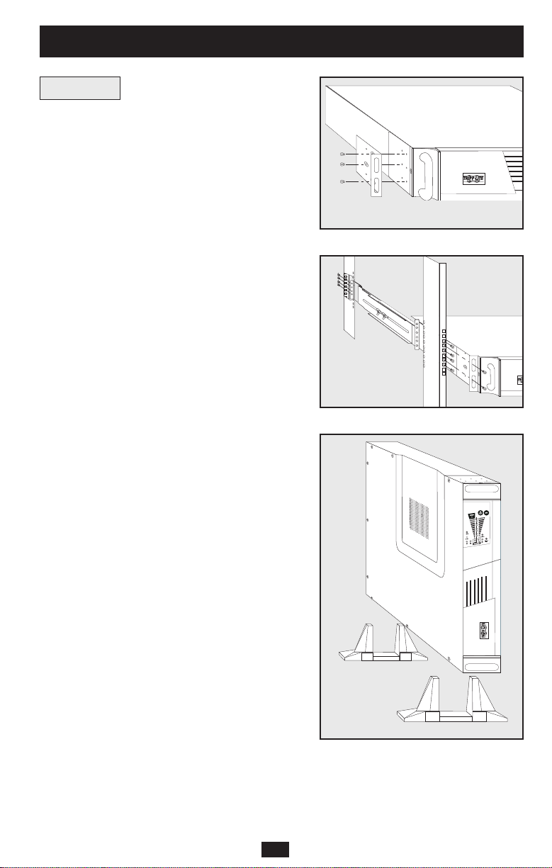
Rackmount
1) Loosen the wingnuts on each of the two UPS
Side Supports; adjust the length of the supports to
match the depth of your rack; tighten wingnuts.
2) Mount both UPS Side Supports in your rack on
the inside surfaces of the rack rails.
Note: Both support ledges should face inward. The side supports’
front and back holes are threaded and do not require nuts to
secure rack bolts.
3) Attach mounting ‘ears’ to the front end of the
UPS’s sides using the screws provided.
4) Lift UPS and slide it onto the UPS Side
Supports within your rack. Mount the UPS by
screwing rack bolts through the UPS mounting
‘ears’, through the rack rails and through the UPS
Side Supports.
Note: The side supports’ front holes are threaded and do not
require nuts to secure rack bolts.
Vertical Tower Mount
1) Cover the rackmount screw holes on the UPS’s
sides with supplied snap-in hole-cover caps.
2) Place the UPS upright in a flat, stable location
with its control panel on the high corner facing
forward. Position stabilizer feet 4 in. from each
end of the UPS.
Mounting
SU2200RTXL2U shown
SU2200RTXL2U shown
3
Installation
Page 4
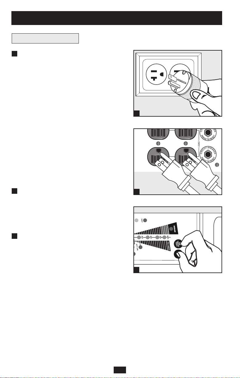
Connection and Start-Up
Plug your UPS’s line cord into an
electrical outlet.
If your model features a detachable line cord,
first plug the female end into your UPS’s AC
Input Receptacle.
Your UPS must be connected to a dedicated
circuit of sufficient amperage—check the
“Recommended Utility Amps” rating of your
model in the specifications. Note, however, that
the select models may be fitted with different
plug types. Refer to the “OP Rating/Plug
Rating” chart printed on the top of your UPS.
Once your UPS is plugged in, the fan and all
Indicator Lights will turn ON. The “LINE” and
“LOAD ACTIVE METER” LEDs will illuminate
and the UPS will emit a beep to indicate normal
operation. However, power is not supplied to
your UPS’s AC outlets until the UPS is turned on.
Plug your equipment into your UPS.
Your UPS is designed to support computer
equipment only. You will overload your UPS if
you connect household appliances or laser
printers to the UPS's outlets.
Turn your UPS ON:
• Press the “ON/TEST” Switch
• Hold it for several seconds until you
hear a beep
• Release it
Your UPS will begin providing AC power to its outlets.
The “ON LINE” LED will illuminate.
SU2200RTXL2U Plug
(NEMA 5-20) shown
1
1
2
3
2
3
SU2200RTXL2U shown
4
Installation
(continued)
Page 5
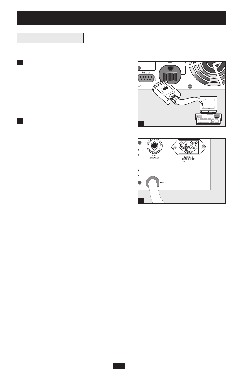
Optional Connections
Your UPS will function properly without these connections.
Serial Port Connection
Using the serial cable provided, connect a serial
port on your computer to the serial port of your
UPS. See Communications in the Basic
Operation section of this manual to determine
how to monitor and manage your UPS using
this port.
External Battery Pack Connection
Check to ensure that the external batteries you
are connecting match the voltage listed on your
UPS’s battery connector. Plug either end of the
battery connection cable (supplied with the
battery pack) into the UPS’s External Battery
Connector and the other end into the Battery
Output Connector on the rear panel of the
external battery pack.
Since your UPS has internal batteries, external
batteries are only needed to extend runtime.
Adding external batteries will increase
recharge time as well as runtime. Make sure
that each end of the cable is fully inserted into
its connector. Several small sparks may result
during battery connection; this is normal.
1
2
1
2
SU2200RTXL2U shown
SU2200RTXL2U shown
5
Installation
(continued)
48V/26A
Page 6
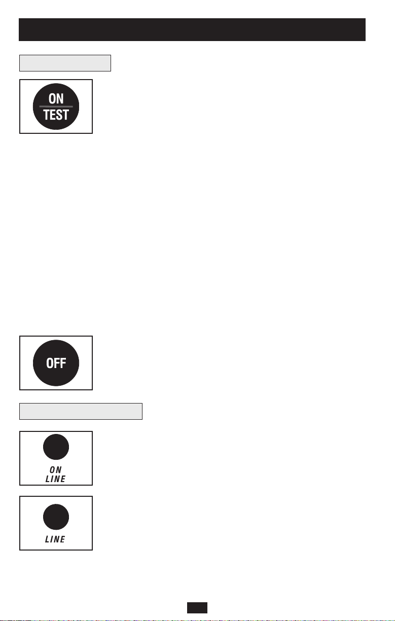
Front Panel Switches
“ON/TEST” Switch: This switch controls four separate UPS functions:
UPS Power ON
To turn the UPS on, press this switch, hold it for several seconds until
you hear a beep, then release it. The “ON LINE” LED will illuminate.
UPS Self-Test
During normal on-line operation, press this switch and hold it until
you hear a beep. This initiates a 10-second self-test of the battery. The
UPS will shift to battery power (the “ON BATT” and “BATT
ACTIVE METER” LEDs will illuminate) for ten seconds.
Alarm Silence
To silence the UPS “on-battery” alarm, press this switch and hold it
until you hear a beep.
UPS Cold Start
To use your UPS as a stand-alone power source when AC power is
unavailable (i.e. during a blackout), press this switch and hold it until
you hear a beep. The UPS will then provide battery power to its outlets.*
* The “ON BATT” Indicator Light will be illuminated since your UPS will be operating
from battery power.
“OFF” Switch: This switch turns power OFF at the UPS receptacles.
Press this switch, hold it until you hear a beep, then release it. The
UPS will continue charging and the fan will continue to cool internal
components even after you turn the UPS receptacles off. To turn the
UPS OFF completely, including the charger, disconnect the UPS’s
power cord after pressing the “OFF” switch.
“ON LINE” LED: This green light will illuminate constantly to indicate
the UPS is performing normal on-line operation (filtering and
resynthesizing incoming AC line voltage to provide pure sine wave
output). When this light is illuminated, you can monitor the load level
of your UPS on the “LOAD ACTIVE METER” LEDs.
“LINE” LED: This green light will illuminate constantly to indicate
the utility supplied AC line voltage at your wall outlet is nominal. It
will flash if the line voltage is outside the nominal range (either too
low or two high). No action is required on your part when the LED
flashes; the UPS continuously and automatically filters AC line
power to provide your equipment with pure sine wave AC power,
regardless of brownout or overvoltage conditions. If this light is off,
then AC line voltage is not present (blackout) or is at an extremely
high voltage, and the UPS will provide connected equipment with
power from battery.
Front Panel Indicator Lights
6
Basic Operation
Page 7
Front Panel Indicator Lights
continued
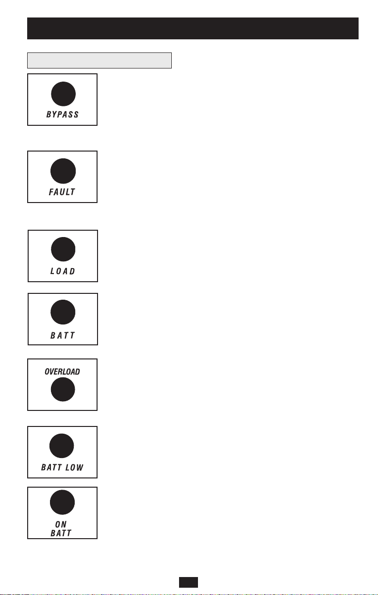
“BYPASS” LED: This yellow light will illuminate to indicate that
the UPS’s DC/AC inverter is deactivated and the UPS is in the
“Bypass” mode. During normal operation this LED will light briefly
when the unit is plugged in, but if an internal fault or overload occurs
this light will illuminate constantly to show that connected equipment
will receive filtered AC mains power, but will not receive battery
power during a blackout. In this case, contact Tripp Lite for service.
“FAULT” LED: This red light will flash when your UPS detects an
internal fault (overheating, overvoltages, etc.) or when it detects a
wiring fault in your wall outlet (reversed phases, missing ground, etc.)
The UPS will only detect wiring faults when it is plugged into a utility
outlet but not turned ON. If the light persists after restarting the UPS,
contact an electrician to check the AC line. Your UPS will identify the
presence of most (but not all) wiring faults.
“LOAD ACTIVE METER” LED: This green light will illuminate
when your UPS is receiving AC power to indicate that the set of four
dual-function LEDs is displaying the load level of your UPS.
“BATT ACTIVE METER” LED: This green light will illuminate
when your UPS is operating from battery power to indicate that the
set of four dual-function LEDs is displaying the battery charge level
of your UPS. Note: the “ON BATT” LED will also be illuminated.
“OVERLOAD” LED: This red light will illuminate constantly to indicate
that your UPS’s capacity has been exceeded while it is in on-line operation.
The UPS alarm will beep continuously. Immediately remove overload
until light and alarm goes off. If you do not immediately remove the
overload, the UPS will transfer from on-line to bypass operation.
“BATT LOW” LED: This yellow light will illuminate when your UPS’s
battery charge level is low. The UPS alarm will beep until either the
battery charge is depleted or the batteries are adequately recharged.
“ON BATT” LED: This green light will illuminate constantly to
indicate that AC line voltage is not present and your UPS is providing
your equipment with battery power. The UPS will also beep every two
seconds, unless silenced by the “ON/TEST” Switch. When this light
is illuminated, you can monitor the battery charge level of your UPS
on the “BATT ACTIVE METER” LEDs.
7
Basic Operation
(continued)
Page 8
Rear Panel
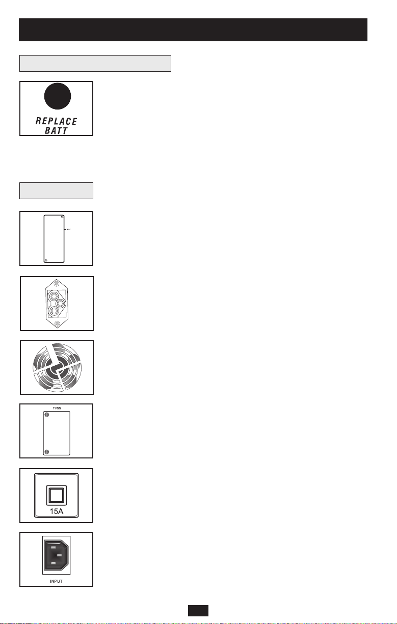
“REPLACE BATT” LED: This red light will illuminate constantly
and the UPS alarm will sound three beeps* if your UPS’s
microprocessor detects a battery fault or if your UPS fails the
automatic self-test (after you turn your UPS ON) and the UPS battery
is less than fully charged. Let the UPS system charge for at least 12
hours and perform a self test using the "ON/Test Switch" as described on
page 6. If the light continues to stay on, contact Tripp Lite for service.
*After the initial alarm, the UPS will beep once every hour until the problem is corrected.
Accessory Slot: Remove the small cover panel from this slot to use
optional accessories to remotely monitor and control your UPS.
Contact Tripp Lite Customer Support at (773) 869-1234 for more
information, including a list of available SNMP, network management
and connectivity products.
External Battery Pack Connector: Use to connect optional Tripp Lite
Battery Packs for additional runtime. Contact Tripp Lite Customer
Support at (773) 869-1234 for the appropriate Tripp Lite battery pack
to connect. Refer to instructions available with the Battery Pack for
complete connection information and safety warnings.
Fan: The fan cools the UPS’s internal components. It is always on
when line power is present.
TVSS Cover Plate: Remove this plate to install optional modem/network
surge protection modules, available for purchase by special
arrangement with Tripp Lite.
Input Circuit Breaker Switch: This resettable breaker prevents high
input current from damaging the UPS or the attached load. If this
breaker trips, make sure your UPS is connected to AC power of the
proper voltage before resetting the circuit breaker by pushing the
breaker switch in.
Input Receptacle (Select Models Only): Connect one end of the
detachable line cord into this receptacle and the other into your wall outlet.
Front Panel Indicator Lights
continued
8
Basic Operation
(continued)
Page 9
Rear Panel
continued
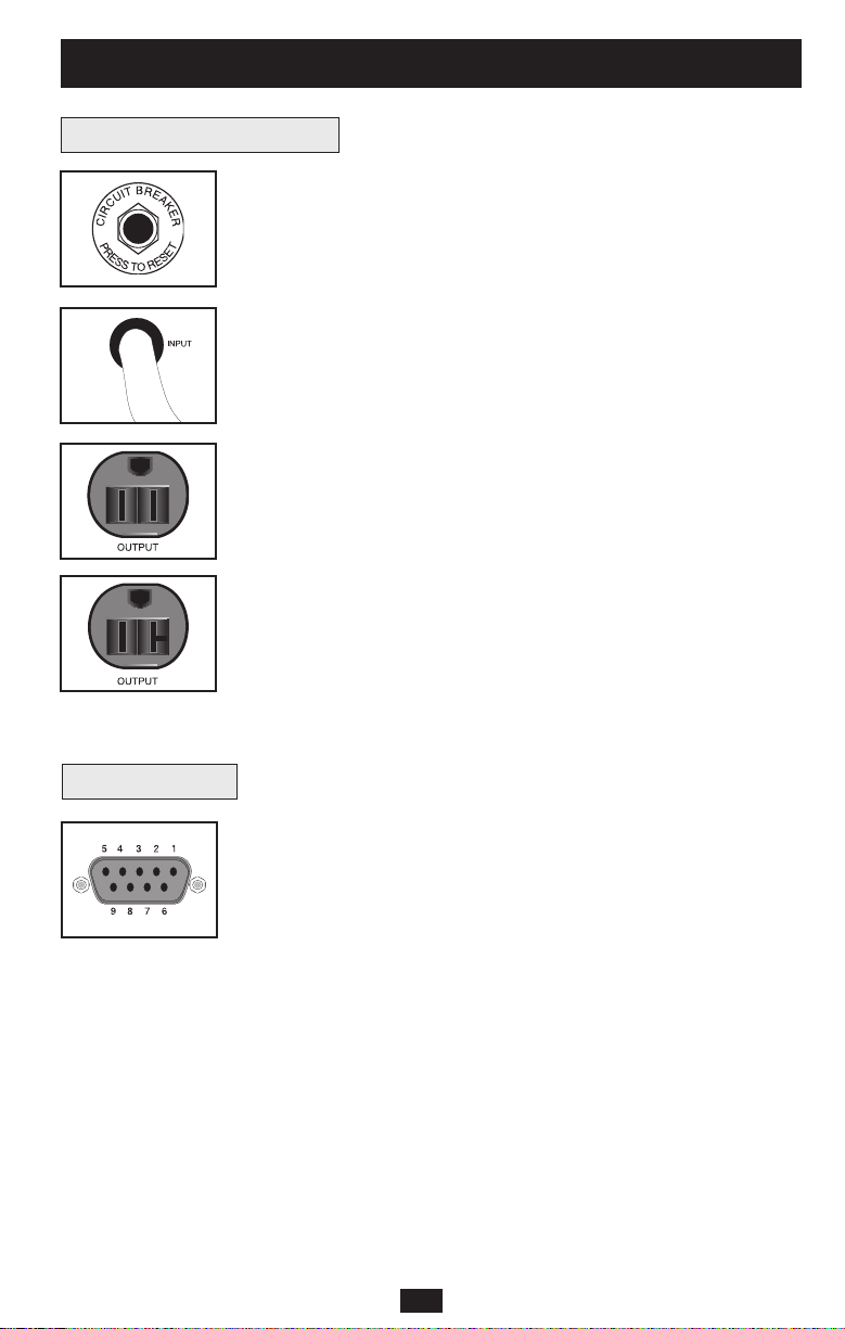
Output Circuit Breakers Switches (Select Models Only): These
resettable circuit breakers protect your UPS from output overload. If
one or both breakers trip, remove some of the load on the circuit(s)
and allow the UPS to cool before pressing the breaker switch(es) in to
reset.
Input Cord (Select Models Only): This permanently attached power
cord connects your UPS to a power outlet.
AC Receptacles (Varied by Model): These 15-, 20- and 30-amp
receptacles provide your connected equipment with pure sine-wave
AC output from the AC line during normal operation and from battery
power during blackouts and severe brownouts. Power provided at
these outlets is filtered to protect connected equipment against
damaging surges and line noise. The receptacles are divided into
numbered load banks, as labelled on the unit. Using PowerAlert
software and cabling, load banks one and two may be individually
turned off and on from a remote location, allowing users to reset or
reboot connected equipment. See Serial Port Connection under
Optional Connections.
“SMART” DB9 Port:Your UPS’s DB9 port can be used to monitor
and control your UPS using either RS-232 or dry contact protocols. It
can also be used to connect an emergency power off (EPO) switch.
RS-232 communications are very complex, but are easy to implement.
The easiest way monitor and control the UPS using RS-232 is to
connect the UPS to a computer with a DB9 cable and install Tripp
Lite’s PowerAlert software on the connected computer.
Dry contact communications are simple, but some knowledge of
electronics is necessary to configure them. The DB9 port’s pin
assignments are shown in the diagram at the left. If the UPS battery is
low, the UPS sends a signal by bridging pin 1 and pin 5. If utility
power fails, the UPS sends a signal by bridging pin 8 and pin 5. To
shut the UPS down remotely, send a 5V to 12V signal on pin 3 (using
pin 5 as the (negative) ground) for at least 3.8 seconds.
You may connect your UPS to an EPO switch and a computer at once
using a Tripp Lite EPO cable (not included; order accessory #73-0901
from Tripp Lite). Follow the connection procedures included with the
EPO Cable.
NEMA 5-15R
NEMA 5-15/20R
Other outlet types not shown
Communications
9
Basic Operation
(continued)
Page 10

The UPS’s control panel lights will turn on in the sequences below to signal that the UPS is
having operational difficulties.
Lights (On/Flashing) and Condition Solution
On: REPLACE BATT Let the UPS system charge for at least
Condition: Replace Battery 12 hours and perform a self test using
the "ON/Test Switch" as described on
page 6. If the light continues to stay on,
contact Tripp Lite for service.
On: BATT LOW, ON BATT Prepare for imminent UPS shutdown.
Condition: Battery Low
On: BYPASS, LINE, LOAD, OVERLOAD Reduce the load the UPS supports.
Condition: On Bypass due to Overload
On: FAULT Remove the cause of the short circuit
Condition: Short Circuit from the UPS output.
Flashing: FAULT Check the utility line for wiring problems
Condition: Wiring Fault such as reversed line and neutral or a
missing ground.
On: FAULT, REPLACE BATT Restart the UPS. If the problem persists,
Condition: Battery Voltage too High contact Tripp Lite for repairs.
On: FAULT, REPLACE BATT, OVERLOAD Restart the UPS. If the problem persists,
Condition: EEPROM Error contact Tripp Lite for repairs.
On: FAULT, BYPASS, LINE, 100% Restart the UPS. If the problem persists,
Condition: On Bypass due to contact Tripp Lite for repairs.
High Output Voltage
On: FAULT, BYPASS, LINE, 75% Restart the UPS. If the problem persists,
Condition: On Bypass due to contact Tripp Lite for repairs.
Low Output Voltage
On: FAULT, BYPASS, LINE, 50% Restart the UPS. If the problem persists,
Condition: On Bypass due to High contact Tripp Lite for repairs.
Bus Voltage
On: FAULT, BYPASS, LINE, 25% Restart the UPS. If the problem persists,
Condition: On Bypass due to Low contact Tripp Lite for repairs.
Bus Voltage
Troubleshooting
10
Page 11

Troubleshooting
(continued)
Lights (On/Flashing) and Condition Solution
On: FAULT, BYPASS, LINE, 100%, 75% Check the UPS to be sure that there is
Condition: On Bypass due to High adequate space for air to circulate near
Internal Temperature the vents and that the fan is working
properly. Restart the UPS.
Flashing: LINE This indicates that utility power is too high
Condition: Input Abnormal or low for the UPS to operate in BYPASS
mode, so if an inverter failure occurs,
the UPS will deliver no output.
On: FAULT, 100% Restart the UPS. If the problem persists,
Flashing: LINE, BYPASS contact Tripp Lite for repairs.
Condition: No Output due to High
Output Voltage and Abnormal Input
Flashing: LINE, BYPASS
Restart the UPS. If the problem persists,
On: FAULT, 75% contact Tripp Lite for repairs.
Condition: No Output due to Low
Output Voltage and Abnormal Input
Flashing: LINE, BYPASS Restart the UPS. If the problem persists,
On: FAULT, 50% contact Tripp Lite for repairs.
Condition: No Output due to High
Bus Voltage and Abnormal Input
Flashing: LINE, BYPASS Restart the UPS. If the problem persists,
On: FAULT, 25% contact Tripp Lite for repairs.
Condition: No Output due to Low
Bus Voltage and Abnormal Input
Flashing: LINE, BYPASS Check the UPS to be sure that there is
On: FAULT, 100%, 75% adequate space for air to circulate near
Condition: No Output due to High the vents and that the fan is working
Internal Temperature and Abnormal properly. Restart the UPS. If the problem
Input persists, contact Tripp Lite for repairs.
11
Page 12
Under normal conditions, the original battery in your UPS will last several years. Contact Tripp Lite
for information about replacement batteries.
Battery replacement should be performed only by qualified service personnel. The batteries are
hot-swappable: it is not necessary to turn off or disconnect the UPS and its connected load to
replace the UPS’s batteries. However, when it is convenient to do so, service personnel may
simplify the replacement procedure by turning power off at the UPS outlets by pressing the
OFF switch to and disconnecting the UPS’s power cord from the wall outlet.
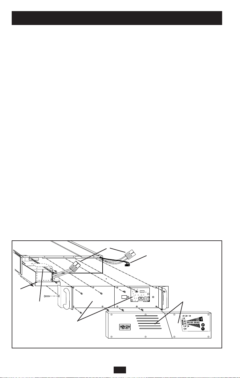
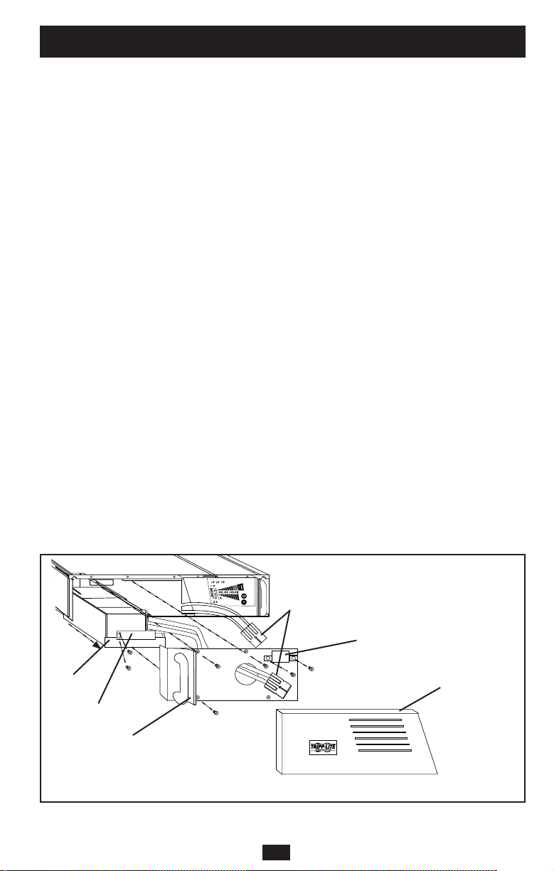
When replacing the batteries on a SU1000RTXL2U, SU1000RTXL2UHV or
SUINT1000RTXL2U, qualified service personnel should refer to “Battery Warnings” in the
Safety section and follow this procedure:
1) Place the UPS horizontal with the Control Panel on the right side.
2) Remove both snap-on cover panels (A).
3) Unscrew and remove rack handle plates (B) on either side of the UPS.
4) Disconnect the microprocessor circuit board plug (C) located on the right side of the UPS.
5) Disconnect battery connectors (D). Note: while batteries are disconnected, the UPS will
not provide battery backup in the event of a power outage.
6) Unscrew and remove the battery retaining bracket (E).
7) Grasp pull-tab and pull out sliding battery tray (F).
8) Make a detailed sketch of the batteries and the polarity, color and connection of all cables.
Disconnect used batteries and dispose of them properly. Connect replacement batteries in
exactly the way the original batteries were connected. Note: Small sparks arcing between
battery connectors during battery replacement are normal. Reassemble the UPS by reversing
steps 1-7. Note: you may not receive full runtime until your new batteries have fully charged.
SU1000RTXL2U shown
B
C
F
E
A
D
12
Battery Replacement
Page 13
Battery Replacement
(continued)
A
D
C
F
When replacing the batteries on a SU1500RTXL2U, SU1500RTXL2UHV, SUINT1500RTXL2U,
SU2200RTXL2U, SU2200RTXL2UHV, SUINT2200RTXL2U, SU3000RTXL2U,
SU3000RTXL2UHV or SUINT3000RTXL2U, qualified service personnel should refer to
“Battery Warnings” in the Safety section and follow this procedure:
1) Place the UPS horizontal with its control panel on the right side.
2) Remove the left snap-on cover panel (A).
3) Unscrew and remove the battery connector cover (B).
4) Disconnect battery connectors (C). Note: while batteries are disconnected, the UPS will
not provide battery backup in the event of a power outage.
5) Unscrew and remove the battery cover plate (D).
6) Unscrew and remove the battery retaining bracket (E).
7) Grasp pull-tab and pull out sliding battery tray (F).
8) Make a detailed sketch of the batteries and the polarity, color and connection of all cables.
Disconnect used batteries and dispose of them properly. Connect replacement batteries in
exactly the way the original batteries were connected. Note: Small sparks arcing between
battery connectors during battery replacement are normal. Reassemble the UPS by reversing
steps 1-7. Note: you may not receive full runtime until your new batteries have fully charged.
SU2200RTXL2U shown
E
B
13
Page 14
Storage and Service
First turn your UPS OFF: press the “OFF” switch to turn power off at the UPS outlets, then
disconnect the power cord from the wall outlet. Next, disconnect all equipment to avoid battery
drain. If you plan on storing your UPS for an extended period of time, fully recharge the UPS
batteries once every three months by plugging the UPS into a live AC outlet and letting the UPS
charge for 4-6 hours. If you leave your UPS batteries discharged for an extended period of time,
they may suffer permanent loss of capacity.
If returning your UPS to Tripp Lite, please carefully pack the UPS using the ORIGINAL
PACKING MATERIAL that came with the unit. Enclose a letter describing the symptoms of the
problem. If the UPS is within the 2 year warranty period, enclose a copy of your sales receipt.
Storage
Service
Specifications
All Models: Input Frequency (50/60 Hz Auto-Selecting); Output Waveform in Line and Battery Modes (Pure Sine Wave);
Transfer Time: (0 ns.); Maximum Harmonic Distortion with Linear Load (< 3%); Maximum Harmonic Distortion with
Nonlinear Load (< 6%); Battery Recharge Time to 80% Capacity (2-4 hours).
Model SU1000RTXL2U SU1000RTXL2UHV SUINT1000RTXL2U
Input Voltage (< 70% Load): 65-138V 130-275V 130-275V
Input Voltage (Full Load): 80-138V 160-275V 160-275V
Output Voltage: 120V 208V 230V
Input Breaker Rating: 15A 8A 8A
Input Plug Type: 5-15P 6-15P IEC 320-C14
Recommended Utility Amps: 15A 15A 10A
Output Capacity (VA/Watts): 1000/800 1000/800 1000/800
Battery Runtime (Half Load/Full Load) Min.: 18/6 18/6 18/6
System Battery Voltage: 36 VDC 36 VDC 36 VDC
Approvals: UL, cUL, FCC, NOM UL, cUL, FCC, NOM CE
Model: SU1500RTXL2U SU1500RTXL2UHV SUINT1500RTXL2U
Input Voltage (< 70% Load): 65-138V 130-275V 130-275V
Input Voltage (Full Load): 80-138V 160-275V 160-275V
Output Voltage: 120V 208V 230V
Input Breaker Rating: 20A 10A 10A
Input Plug Type: 5-15P 6-20P IEC 320-C14
Recommended Utility Amps: 20 A 15 A 15 A
Output Capacity (VA/Watts): 1500/1200 1500/1200 1500/1200
Battery Runtime (Half Load/Full Load) Min.: 17/5 17/5 17/5
System Battery Voltage: 48 VDC 48 VDC 48 VDC
Approvals: UL, cUL, FCC, NOM UL,cUL, FCC, NOM CE
Model SU2200RTXL2U SU2200RTXL2UHV SUINT2200RTXL2U
Input Voltage (< 70% Load): 65-138V 130-275V 130-275V
Input Voltage (Full Load): 80-138V 160-275V 160-275V
Output Voltage: 120V 208V 230V
Input Breaker Rating: 30A 15A 15A
Input Plug Type: 5-20P 6-20P IEC 320-C20
Recommended Utility Amps: 20A 20A 20A
Output Capacity (VA/Watts): 2200/1600 2200/1600 2200/1600
Battery Runtime (Half Load/Full Load) Min.: 18/6 18/6 18/6
System Battery Voltage: 48 VDC 48 VDC 48 VDC
Approvals: UL, cUL, FCC, NOM UL, cUL, FCC, NOM CE
14
Page 15

Specifications
(continued)
Model SU3000RTXL3U SU3000RTXL3UHV SUINT3000RTXL3U
Input Voltage (< 70% Load): 65-138V 130-275V 130-275V
Input Voltage (Full Load): 80-138V 160-275V 160-275V
Output Voltage: 120V 208V 230V
Input Breaker Rating: 40A 25A 25A
Input Plug Type: L5-30P L6-20P IEC 320-C20
Recommended Utility Amps: 30A 20A 20A
Output Capacity (VA/Watts): 3000/2400 3000/2400 3000/2400
Battery Runtime (Half Load/Full Load) Min.: 14/6 14/6 14/6
System Battery Voltage: 72 VDC 72 VDC 72 VDC
Approvals: UL, cUL, FCC, NOM UL, cUL, FCC, NOM CE
The policy of Tripp Lite is one of continuous improvement. Specifications are subject to change without notice.
FCC Specifications for Models with FCC Approval: This device complies with part 15 of the FCC Rules.
Operation is subject to the following two conditions: (1) This device may not cause harmful interference, and
(2) this device must accept any interference received, including interference that may cause undesired operation.
This equipment has been tested and found to comply with the limits for a Class A digital device, pursuant to
part 15 of the FCC Rules. These limits are designed to provide reasonable protection against harmful interference
when the equipment is operated in a commercial environment. This equipment generates, uses, and can radiate
radio frequency energy and, if not installed and used in accordance with the instruction manual, may cause
harmful interference to radio communications. Operation of this equipment in a residential area is likely to cause
harmful interference in which case the user will be required to correct the interference at his own expense.The
user must use shielded cables and connectors with this product. Any changes or modifications to this product
not expressly approved by the party responsible for compliance could void the user’s authority to operate the
equipment.
15
Page 16

16
Page 17

Manual del usuario
1111 W. 35 th St re et Ch icago, IL 60609 EE.UU.
Atención al cliente: (773) 869-1234 • www.tripplite.com
Importantes instrucciones de seguridad
18
Instalación
19
Operación básica
22
Reemplazo de la batería
28
Almacenamiento y servicio
30
SmartOnline
™
Sistemas UPS en línea con montaje en bastidor/torre
Especificaciones
30
English
Français
33
1
© 2002 Tripp Lite. Todos los derechos reservados. SmartOnline™ es una marca registrada de Tripp Lite.
Localización de fallas
26
Page 18

Advertencias sobre la colocación del UPS
• Instale el sistema UPS bajo techo, alejado del calor o la humedad excesivos, de los
contaminantes conductivos, del polvo o de la luz solar directa.
• Para lograr el mejor rendimiento, mantenga la temperatura interior entre 0º C y 40º C
(32º F y 104º F).
• Mantenga suficiente espacio alrededor del sistema UPS para permitir una ventilación
adecuada.
Advertencias sobre la conexión del UPS
• Conecte su sistema UPS directamente a una toma de corriente de CA con una conexión a
tierra adecuada. No conecte el sistema UPS a sí mismo, ya que esto lo dañará.
• No modifique los conectores del UPS y no utilice un adaptador que pueda eliminar la
conexión a tierra del sistema.
• No utilice cables de extensión para conectar el UPS en la toma de corriente de CA. Si se
utiliza otro tipo de supresor de sobretensión que no sea Tripp Lite para conectar el UPS a
la toma de corriente, se anulará la garantía del sistema.
• Si el sistema UPS recibe energía eléctrica por medio de un generador de CA accionado
por motor, éste deberá proporcionar una salida de corriente limpia y filtrada del tipo
utilizado para computadoras.
Advertencias sobre la conexión de equipos
• No utilice los sistemas UPS de Tripp Lite en equipo para el soporte de la vida humana,
donde un fallo o mal funcionamiento podría causar anomalías o alterar
significativamente el rendimiento del dispositivo para el soporte de la vida humana.
• No conecte supresores de sobretensión o cables de extensión a la salida del sistema UPS.
Esto podría dañar el UPS y anularía la garantía del supresor de sobretensiones y del UPS.
Advertencias sobre las baterías
• El sistema UPS no requiere ningún mantenimiento rutinario. No abra el UPS por ningún
motivo, excepto para el reemplazo de las baterías. Esta unidad no contiene partes
internas que puedan ser reparadas por el usuario.
• Sólo personal técnico debidamente capacitado puede realizar el reemplazo de las
baterías. Debido a los riesgos que presentan las baterías en relación con los choques
eléctricos y las quemaduras causadas por corriente elevada de corto circuito, el personal
técnico capacitado debe observar todas las precauciones pertinentes. Apague y
desenchufe el sistema UPS antes de reemplazar las baterías. Utilice herramientas con
asas aisladas y reemplace las baterías con el mismo número y tipo de baterías nuevas (de
plomo-ácido selladas). No abra las baterías. No permita que ningún objeto entre en
contacto con los terminales de las baterías.
• Las baterías del sistema UPS son reciclables. Consulte el reglamento local para conocer
los requerimientos de desecho aplicables o en los EE.UU. solamente, llame al 1-800-SAV-LEAD
(1-800-728-5323) para recibir información sobre el reciclaje. No utilice fuego para
desechar las baterías.
• Conecte únicamente paquetes de baterías Tripp Lite del tipo apropiado y del voltaje
correcto en el conector de baterías externas.
• No conecte ni desconecte las baterías externas cuando el sistema UPS está operando con baterías.
• No haga funcionar su UPS sin baterías.
GUARDE ESTAS INSTRUCCIONES
Este manual contiene advertencias e instrucciones importantes que deben seguirse
durante la instalación, operación y almacenamiento de todos los sistemas UPS de Tripp Lite.
De no cumplirse estas advertencias, la garantía será anulada.
18
Importantes instrucciones de seguridad
Page 19

Montaje en bastidor
1) Afloje las tuercas de mariposa en cada uno de
los dos soportes laterales del UPS; ajuste la
longitud de los soportes para que concuerden con
la profundidad del bastidor; apriete las tuercas de
mariposa.
2) Realice el montaje de ambos soportes laterales
del UPS en su bastidor en las superficies de los
rieles del bastidor.
Nota: Ambas salientes del soporte deberán dirigirse hacia
adentro. Los orificios frontal y posterior de los soportes
laterales tienen rosca y no requieren tuercas para asegurar
los pernos del bastidor.
3) Una las lengüetas de montaje al extremo
delantero de los lados del UPS con los tornillos
proporcionados.
4) Levante el UPS y deslícelo dentro del bastidor
sobre los soportes laterales del UPS. Monte el
sistema UPS atornillando los pernos del bastidor
a través de las lengüetas de montaje del UPS, a
través de los rieles y de los soportes laterales del UPS.
Nota: Los orificios frontales de los soportes laterales tienen rosca
y no requieren tuercas para asegurar los pernos del bastidor.
Montaje de torre vertical
1) Cubra los orificios para tornillos del montaje
en bastidor ubicados a los lados del UPS con las
tapas de inserción suministradas.
2) Coloque el UPS en posición vertical en un
lugar plano y firme con el panel de control de la
esquina superior colocado hacia adelante. La
posición de la zapata de equilibrio debe estar a
10.16 cm (4 pulg.) desde cada extremo del UPS.
Montaje
Se muestra SU2200RTXL2U
Se muestra SU2200RTXL2U
19
Instalación
Page 20

Conexión y encendido
Conecte el cable del sistema UPS
a una toma de corriente eléctrica.
Si su modelo tiene un cable de sistema
desmontable, conecte primero el extremo hembra
en el receptáculo de entrada de CA del UPS.
Su UPS debe estar conectado a un circuito
dedicado con un amperaje suficiente—
compruebe la gama de “Amperios de servicio
recomendados” de su modelo en las
especificaciones. Sin embargo, observe que los
modelos seleccionados pueden equiparse con
diferentes tipos de enchufe. Consulte la tabla
“Operación nominal/Conexión nominal”
impresa en la parte superior de su UPS.
Una vez que su UPS está enchufado, se
encenderá la luz del ventilador y todas las
luces indicadoras. Los LED “LINE” (Línea) y
“LOAD ACTIVE METER” (Medidor activo de
carga) se encenderán y el UPS emitirá un sonido
que indica funcionamiento normal. Sin embargo,
no se suministra energía a las tomas de corriente
de CA de su UPS hasta que se éste encienda.
Enchufe su equipo al sistema UPS.
Su sistema UPS está diseñado para soportar
únicamente equipo informático. Usted lo
sobrecargará si conecta electrodomésticos o
impresoras láser a las tomas de corriente del UPS.
Encienda su sistema UPS (ON):
• Presione el interruptor “ON/TEST”
(Encendido/Prueba).
• Manténgalo presionado por varios segundos
hasta que escuche un sonido.
• Suelte el interruptor.
Su sistema UPS empezará a suministrar energía CA a sus tomas
de corriente. Se iluminará el LED “ON LINE” (En línea).
Se muestra el enchufe
SU2200RTXL2U (NEMA 5-20)
1
1
2
3
2
3
Se muestra
SU2200RTXL2U
20
Instalación
(continuación)
Page 21

Conexiones opcionales
Este sistema UPS funcionará correctamente sin estas conexiones.
Conexión de puerto serial
Utilice el cable serial incluido, conecte un
puerto serial de su computadora al puerto serial
de su UPS. Vea la sección Comunicaciones en
operación básica de esta manual para
determinar cómo monitorear y administrar el
sistema UPS a través de este puerto.
Conexión del paquete de baterías
externas
Verifique que las baterías externas que desea
conectar tengan el mismo voltaje de la lista que
aparece en el conector para baterías del UPS.
Conecte cualquier extremo del cable de
conexión de batería (proporcionado con el
paquete de baterías) en el conector para
baterías externas del UPS y el otro extremo en
el conector de salida de la batería que se
encuentra en el panel posterior del paquete de
baterías externas.
Debido a que su UPS ya posee baterías
internas, las baterías externas son necesarias
sólo para prolongar el tiempo de
funcionamiento. Si agrega baterías externas
incrementará el tiempo de recarga así como el
tiempo de respaldo. Asegúrese de que cada
extremo del cable esté completamente
insertado en su conector. Es normal que se
produzcan pequeñas chispas durante la
conexión de las baterías.
1
2
1
2
Se muestra SU2200RTXL2U
Se muestra SU2200RTXL2U
21
Instalación
(continuación)
48V/26A
Page 22

Interruptores del panel frontal
Interruptor “ON/TEST” (Encendido/Prueba): Este interruptor
controla cuatro funciones separadas del UPS:
UPS encendido: Para encender el UPS, presione el interruptor,
manténgalo presionado por varios segundos hasta que escuche un
sonido y suéltelo. Se encenderá el LED “ON LINE”.
Autoprueba del UPS: Durante una operación en línea normal,
presione el interruptor y manténgalo presionado hasta que escuche un
sonido. Esto inicia una autoprueba de la batería que dura 10
segundos. El UPS cambiará a energía de baterías (se iluminarán los
LED “ON BATT” y “BATT ACTIVE METER”) durante diez segundos.
Silenciar alarma: Para silenciar la alarma del UPS “en batería”,
presione el interruptor y manténgalo presionado hasta que escuche un
sonido.
Encendido en frío del UPS: Para usar su UPS como una fuente de
energía autónoma cuando no haya energía de CA disponible (es decir,
durante un apagón), presione este botón y manténgalo presionado
hasta que escuche un sonido. El UPS suministrará entonces energía de
las baterías a sus tomas de corriente.*
* La luz indicadora “ON BATT” se iluminará cuando su UPS esté operando con
energía de las baterías.
Interruptor “OFF” (Apagado): Este interruptor apaga el suministro
de energía en los receptáculos del UPS. Presione el interruptor,
manténgalo presionado hasta que escuche un sonido y suéltelo. El
UPS seguirá cargando y el ventilador seguirá enfriando los
componentes internos incluso después de haber apagado los
receptáculos del UPS. Para apagar completamente el UPS, incluido el
cargador, desconecte el cable de energía del UPS después de
presionar el interruptor “OFF”.
LED “ON LINE”: Esta luz verde se iluminará y permanecerá fija para
indicar que el UPS está en operación en línea normal (filtrado y
resintetizado del voltaje de la línea de CA entrante para proporcionar
una salida en forma de onda sinusoidal pura). Cuando esta luz está
encendida, puede controlar el nivel de carga del UPS en los LED
“LOAD ACTIVE METER”.
LED “LINE” (Línea): Esta luz verde se iluminará y permanecerá
fija para indicar que el voltaje de la línea de CA proporcionada por el
suministro en su toma de energía es nominal. La luz parpadeará si el
voltaje de la línea se encuentra fuera del valor nominal (ya sea
demasiado bajo o demasiado alto). No necesita hacer nada cuando el
LED parpadea; el UPS filtra de manera continua y automática la
energía de la línea de CA para suministrar a su equipo energía de CA
de onda sinusoidal pura, sin considerar las condiciones de baja o alza
de voltaje. Si esta luz está apagada, quiere decir que no hay voltaje de
línea de CA (apagón) o que hay un voltaje muy alto y que el UPS
proporcionará energía a los equipos conectados desde la batería.
Luces indicadoras del panel frontal
22
Operación básica
Page 23

Luces indicadoras del panel frontal
continuación
LED “BYPASS” (Derivación): Esta luz amarilla se ilumina para
indicar que el inversor de CC/CA del UPS se encuentra desactivado y el
UPS está en el modo “Derivación”. Durante el funcionamiento normal,
este LED se iluminará brevemente al momento de enchufar la unidad,
pero en caso de ocurrir una falla o sobrecarga interna, la luz
permanecerá fija para indicar que el equipo conectado recibirá energía
eléctrica de CA filtrada, pero no la energía de las baterías durante un
apagón. En este caso, contáctese con Tripp Lite para obtener servicio
técnico.
LED “FAULT” (Falla): Esta luz roja parpadeará cuando su sistema
UPS detecte una falla interna (sobrecalentamiento, sobrevoltajes, etc.)
o cuando detecte una falla de cableado en las tomas de corriente (fases
invertidas, ausencia de tierra, etc.). El UPS detectará fallas de
cableado sólo cuando se encuentre conectado a una toma de energía
eléctrica que no esté encendida. Si la luz sigue encendida después de
reiniciar el UPS, comuníquese con un electricista para revisar la línea
de CA. Su UPS identificará la mayoría (pero no todas) las fallas de
cableado.
LED “LOAD ACTIVE METER” (Medidor activo de carga): Esta
luz verde se encenderá cuando su UPS reciba energía de CA para
indicar que el grupo de cuatro luces LED de doble funcionalidad está
indicando el nivel de carga de su UPS.
LED “BATT ACTIVE METER” (Medidor activo de batería):
Esta luz verde se encenderá cuando su UPS funcione en base a la
energía de la batería para indicar que el grupo de cuatro luces LED de
doble funcionalidad está mostrando el nivel de carga de la batería de
su UPS. Nota: también se encenderá el LED “ON BATT”.
LED “OVERLOAD” (Sobrecarga): Esta luz roja se iluminará y
permanecerá fija para indicar que se excedió la capacidad de su UPS
mientras esté funcionando en línea. La alarma del UPS emitirá un sonido
continuo. Retire inmediatamente la sobrecarga hasta que se apague la
luz y la alarma. En caso de no retirar la sobrecarga inmediatamente, el
UPS cambiará de operación en línea a operación de derivación.
LED “BATT LOW” (Batería baja): Esta luz amarilla se encenderá
cuando el nivel de carga de la batería de su UPS esté bajo. La alarma
del UPS emitirá un sonido hasta que la carga de la batería se agote
completamente o se recarguen las baterías de manera adecuada.
LED “ON BATT” (En batería): Esta luz verde se iluminará y
permanecerá fija para indicar que no hay voltaje en la línea de CA y
que su UPS está suministrando energía al equipo a través de la batería.
El UPS emitirá un sonido cada dos segundos a menos que lo silencie
con el interruptor “ON/TEST”. Cuando se prende esta luz, puede
controlar el nivel de carga de la batería del UPS en los LED “BATT
ACTIVE METER”.
23
Operación básica
(continuación)
Page 24

Panel posterior
LED “REPLACE BATT” (Reemplazar batería): Esta luz roja se
iluminará y permanecerá fija y la alarma del UPS emitirá tres sonidos*
si el microprocesador del UPS detecta una falla en la batería o si su
UPS falla en la autoprueba automática (después de encendido) y en
caso de que la batería no esté completamente cargada. Deje que el
sistema del UPS se cargue por lo menos 12 horas y realice una
autoprueba usando el interruptor de " ON/Test " según lo descrito en
la página 22. Si la luz permanece encendida, póngase en contacto con
Tripp Lite para solicitar servicio técnico.
*Después de la alarma inicial, el UPS emitirá un sonido cada hora hasta que se
solucione el problema.
Ranura para accesorios: Retire el pequeño panel que cubre esta
ranura para instalar accesorios opcionales utilizados en el monitoreo
y control remoto del sistema UPS. Póngase en contacto con el
Servicio de atención al cliente de Tripp Lite llamando al (773) 869-1234
para obtener más información, incluyendo una lista de los productos
disponibles de SNMP, de administración de redes y de conectividad.
Conector del paquete de baterías externas: Utilícelo para conectar
paquetes de baterías Tripp Lite opcionales si desea tiempo de
funcionamiento adicional. Póngase en contacto con el Servicio de
atención al cliente de Tripp Lite al (773) 869-1234 para obtener el
paquete de baterías Tripp Lite adecuado. Consulte las instrucciones
que vienen con el paquete de baterías para obtener información
completa sobre conexión y advertencias de seguridad.
Ventilador: El ventilador enfría los componentes internos del UPS.
Se encenderá siempre que haya energía de línea presente.
Placa de TVSS: Retire esta placa para instalar módulos de protección de
sobrevoltaje para módem/red, disponibles para compra mediante
acuerdo especial con Tripp Lite.
Interruptor de protección del mando del interruptor de entrada:
Este interruptor reconfigurable evita que una corriente de entrada alta
dañe el UPS o los aparatos conectados a él. Si este interruptor se
dispara, asegúrese de que el sistema UPS está conectado a una
energía de CA del voltaje adecuado antes de reconfigurar el
interruptor empujándolo hacia adentro.
Receptáculo de entrada (Solamente para los modelos
seleccionados): Conecte un extremo del cable de sistema desmontable
en este receptáculo y el otro a la toma de corriente.
Luces indicadoras del panel frontal
continuación
24
Operación básica
(continuación)
Page 25

Panel posterior
continuación
Interruptores de protección del mando del interruptorde salida
(sólo modelos seleccionados): Estos interruptores reconfigurables
protegen su UPS de una sobrecarga de salida. Si uno o ambos
interruptores se dispararan, desconecte algunas de las cargas de los
circuitos y deje que el UPS se enfríe antes de presionar el o los
interruptores para restablecerlos.
Cable de entrada (sólo para modelos seleccionados): Este cable de
energía con conexión fija, conecta su UPS a una toma de corriente.
Receptáculos de CA (según modelo): Estos receptáculos de 15, 20 y
30 amperios le proporcionan a sus equipos salida de CA de onda
sinusoidal pura desde la línea de CA durante una operación normal y
energía desde las baterías durante apagones y severas bajas de voltaje.
La energía suministrada en estas tomas de corriente se filtra con el
objeto de proteger los equipos conectados contra daños y ruido de
línea. Los receptáculos se dividen en bancos de carga numerados,
como está rotulado en la unidad. Con el uso del software PowerAlert
y el cableado, se pueden encender y apagar individualmente los
bancos de carga uno y dos desde una ubicación remota, lo que le
permite a los usuarios restablecer o reiniciar los equipos conectados.
Vea Conexión de puerto serial en Conexiones opcionales.
Puerto DB9 inteligente: Puede usarse el puerto DB9 del UPS para
monitorear y controlar el UPS usando protocolos RS-232 o de
contacto en seco. Puede usarse también para conectar un interruptor
de apagado de energía de emergencia (EPO).
Las comunicaciones de RS-232 son muy complejas, pero fáciles de
implementar. La manera más fácil de monitorear y controlar el UPS
usando RS-232 es conectando éste a una computadora con un cable
DB9 e instalar el software PowerAlert de Tripp Lite en la
computadora conectada.
Las comunicaciones de contacto en seco son simples, pero se necesita
cierto conocimiento de electrónica para configurarlas. Las asignaciones
de las patillas del puerto DB9 se muestran en el diagrama de la
izquierda. Si la batería del UPS está baja, el UPS envía una señal
haciendo puente entre la patilla 1 y la 5. Si el suministro de energía
falla, el UPS manda una señal haciendo puente entre la patilla 8 y la 5.
Para apagar el UPS en forma remota, envíe una señal de 5V a 12V en
la patilla 3 (usando la patilla 5 como tierra (negativo)) durante al
menos 3.8 segundos.
Puede conectar el UPS a un interruptor EPO y a una computadora a la
vez usando un cable EPO Tripp Lite (no incluido; solicite accesorio
Nº 73-0901 de Tripp Lite). Siga los procedimientos de conexión
incluidos con el cable EPO.
NEMA 5-15R
NEMA 5-15/20R
No se muestran otros tipos de salida
Comunicaciones
25
Operación básica
(continuación)
Page 26

Las luces del panel de control del UPS se encenderán en las secuencias descritas a
continuación para indicar que el UPS tiene dificultades de funcionamiento.
Luces (Encendidas/Parpadeando) y condición Solución
Encendidas: REEMPLAZAR BATERÍA Deje que el sistema del UPS se
Condición: Reemplazar batería cargue por lo menos 12 horas y
realice una autoprueba usando el
interruptor de " ON/Test " según lo
descrito en la página 22. Si la luz
permanece encendida, póngase
en contacto con Tripp Lite para
solicitar servicio técnico.
Encendidas: BATERÍA BAJA, EN BATERÍA Prepárese para un apagado
Condición: Batería baja inminente del UPS.
Encendidas: DERIVACIÓN, LÍNEA, CARGA, Reduzca la carga que soporta
SOBRECARGA el UPS.
Condición: En Derivación por sobrecarga
Encendidas: FALLA Retire la causa del cortocircuito
Condición: Cortocircuito de la salida del UPS.
Parpadeando: FALLA Revise la línea de suministro
Condición: Falla de cableado para detectar problemas de
cableado como por ejemplo
línea invertida y neutra o
ausencia de conexión a tierra.
Encendidas: FALLA, REEMPLAZAR BATERÍA Reinicie el UPS. Si el problema
Condición: Voltaje de la batería demasiado alto persiste, póngase en contacto
con Tripp Lite para solicitar
servicio técnico.
Encendidas: FALLA, REEMPLAZAR BATERÍA, Reinicie el UPS. Si el problema
SOBRECARGA persiste, póngase en contacto
Condición: Error de EEPROM con Tripp Lite para solicitar
servicio técnico.
Encendidas: FALLA, DERIVACIÓN, LÍNEA, 100% Reinicie el UPS. Si el problema
Condición: En derivación debido a sobrevoltaje persiste, póngase en contacto
de salida con Tripp Lite para solicitar
servicio técnico.
Encendidas: FALLA, DERIVACIÓN, LÍNEA, 75% Reinicie el UPS. Si el problema
Condición: En derivación debido a bajo voltaje persiste, póngase en contacto
de salida con Tripp Lite para solicitar
servicio técnico.
Encendidas: FALLA, DERIVACIÓN, LÍNEA, 50% Reinicie el UPS. Si el problema
Condición: En derivación debido a sobrevoltaje persiste, póngase en contacto
en bus con Tripp Lite para solicitar
servicio técnico.
Encendidas: FALLA, DERIVACIÓN, LÍNEA, 25% Reinicie el UPS. Si el problema
Condición: En derivación debido a bajo voltaje persiste, póngase en contacto
en bus con Tripp Lite para solicitar
servicio técnico.
Localización de fallas
26
Page 27

Localización de fallas
(continuación)
Luces (Encendidas/Parpadeando) y condición Solución
Encendidas: FALLA, DERIVACIÓN, LÍNEA, Revise el UPS para asegurarse de
100%, 75% que hay suficiente espacio para
Condición: En derivación debido a alta permitir la circulación de aire
temperatura interna cerca de las ranuras de ventilación
y que el ventilador esté funcionando
correctamente. Reinicie el UPS.
Parpadeando: LÍNEA Esto indica que el suministro de
Condición: Entrada anormal energía es demasiado alto o bajo
para que el UPS funcione en mod
o DERIVACIÓN, de modo que si
ocurre una falla del inversor, el UPS
no entregará energía de salida.
Encendidas: FALLA, 100% Reinicie el UPS. Si el problema
Parpadeando: LÍNEA, DERIVACIÓN persiste, en contacto con Tripp Lite
Condición: No hay salida debido a un para solicitar servicio técnico.
sobrevoltaje de salida y entrada anormal
Parpadeando: LÍNEA, DERIVACIÓN Reinicie el UPS. Si el problema
Encendidas: FALLA, 75% persiste, póngase en contacto
Condición: No hay salida debido a un bajo con Tripp Lite para solicitar
voltaje de salida y entrada anormal servicio técnico.
Parpadeando: LÍNEA, DERIVACIÓN Reinicie el UPS. Si el problema
Encendidas: FALLA, 50% persiste, póngase en contacto
Condición: No hay salida debido a un con Tripp Lite para solicitar
sobrevoltaje en bus y entrada anormal servicio técnico.
Parpadeando: LÍNEA, DERIVACIÓN Reinicie el UPS. Si el problema
Encendidas: FALLA, 25% persiste, póngase en contacto
Condición: No hay salida debido a un bajo con Tripp Lite para solicitar
voltaje en bus y entrada anormal servicio técnico.
Parpadeando: LÍNEA, DERIVACIÓN Revise el UPS para asegurarse de
Encendidas: FALLA, 100%, 75% que hay suficiente espacio para
Condición: No hay salida debido a una alta permitir la circulación de aire
temperatura interna y entrada anormal cerca de las ranuras de ventilación
y que el ventilador esté funcionando
correctamente. Reinicie el UPS. Si
el problema persiste, póngase en
contacto conTripp Lite para
solicitar servicio técnico.
27
Page 28

En condiciones normales, las baterías originales de su sistema UPS tienen varios años de vida útil.
Póngase en contacto con Tripp Lite para obtener información sobre el reemplazo de baterías.
El reemplazo de la batería debe realizarlo sólo personal técnico calificado. Las baterías se
pueden reemplazar con el equipo encendido: no es necesario apagar ni desconectar el sistema
UPS y su carga conectada para reemplazar sus baterías. Sin embargo, cuando es conveniente
hacerlo, el personal de servicio técnico puede simplificar el procedimiento de reemplazo
apagando la energía en las salidas del sistema UPS presionando el interruptor OFF (Apagado)
y desconectando su cable de alimentación de la toma de corriente.
Al cambiar las baterías en un modelo SU1000RTXL2U, SU1000RTXL2UHV o
SUINT1000RTXL2U, sólo el personal de servicio técnico calificado debe consultar las
“Advertencias sobre las baterías” en la Sección de seguridad y seguir este procedimiento:
1) Coloque el UPS en posición horizontal con el panel de control al lado derecho.
2) Retire ambos paneles (A).
3) Desatornille y saque las placas de manipulación del bastidor (B) a ambos lados del sistema UPS.
4) Desconecte el conector de la tarjeta de circuitos del microprocesador (C) ubicado a la
derecha del UPS.
5) Desconecte los conectores de batería (D). Nota: mientras las baterías están desconectadas,
el UPS no proporciona respaldo de baterías en el caso de un corte de energía.
6) Desatornille y retire la abrazadera de sujeción de la batería (E).
7) Tome la lengüeta de extracción y saque el portabaterías deslizante (F).
8) Haga un esquema detallado de las baterías y la polaridad, color y conexión de todos los
cables. Desconecte las baterías usadas y elimínelas de manera correcta. Conecte las
baterías de reemplazo exactamente de la misma manera como estaban las baterías
originales. Nota: Es normal que se emitan pequeñas chispas entre los conectores de la
batería al momento de su reemplazo. Vuelva a montar el UPS invirtiendo los pasos 1-7. Nota:
es posible que no obtenga un tiempo de funcionamiento completo hasta que sus baterías
nuevas se hayan cargado completamente.
Se muestra SU1000RTXL2U
B
C
F
E
A
D
28
Reemplazo de la batería
Page 29

Reemplazo de la batería
(continuación)
A
D
C
F
Al cambiar las baterías en un modelo SU1500RTXL2U, SU1500RTXL2UHV, SUINT1500RTXL2U,
SU2200RTXL2U, SU2200RTXL2UHV, SUINT2200RTXL2U, SU3000RTXL2U,
SU3000RTXL2UHV o SUINT3000RTXL2U, el personal de servicio técnico calificado debe
consultar las “Advertencias sobre las baterías” en la sección de Seguridad y seguir este
procedimiento:
1) Coloque el UPS en posición horizontal con el panel de control al lado derecho.
2) Retire el panel que cubre el lado izquierdo (A).
3) Desatornille y retire la tapa del conector de la batería (B).
4) Desconecte los conectores de batería (C). Nota: mientras las baterías están desconectadas,
el UPS no proporciona respaldo de baterías en el caso de un corte de energía.
5) Desatornille y retire la placa que cubre la batería (D).
6) Desatornille y retire la abrazadera de sujeción de la batería (E).
7) Tome la lengüeta de extracción y saque el portabaterías deslizante (F).
8) Haga a esquema detallado de las baterías y la polaridad, color y conexión de todos los
cables. Desconecte las baterías usadas y elimínelas de manera correcta. Conecte las
baterías de reemplazo exactamente de la misma manera como estaban las baterías
originales. Nota: Es normal que se emitan pequeñas chispas entre los conectores de la
batería al momento de su reemplazo. Vuelva a montar el UPS invirtiendo los pasos 1-7.
Nota: es posible que no obtenga un tiempo de funcionamiento completo hasta que sus baterías
nuevas se hayan cargado completamente.
Se muestra SU2200RTXL2U
E
B
29
Page 30

Almacenamiento y servicio
Primero, apague el sistema UPS: presione el interruptor “OFF” para desconectar la
alimentación en las tomas del UPS, luego desconecte el cable de alimentación de la toma de
corriente. Después, desconecte todos sus equipos para evitar el desgaste innecesario de la batería.
Si desea almacenar este sistema UPS por un período prolongado, recargue completamente las
baterías del sistema UPS una vez cada tres meses, conectándolo a una línea de CA que tenga
corriente y permitiéndole que cargue sus baterías por un período de 4 a 6 horas. Si deja las
baterías del sistema UPS descargadas por un periodo de tiempo prolongado, pueden perder su
capacidad en forma permanente.
Si decide devolver su UPS a Tripp Lite, embale cuidadosamente el sistema UPS usando el
MATERIAL DE EMBALAJE ORIGINAL que se proporcionó con la unidad. Adjunte una carta
describiendo los síntomas del problema. Si el sistema UPS se encuentra dentro del periodo de
garantía de 2 años, adjunte una copia de su nota de compra.
Almacenamiento
Servicio
Especificaciones
Todos los modelos: frecuencia de entrada (autoselección de 50/60 Hz ); forma de la onda de salida en los modos Línea
y Batería (onda sinusoidal pura); tiempo de transferencia: (0 ns.); distorsión armónica máxima con carga lineal (< 3%);
distorsión armónica máxima con carga no lineal (< 6%); tiempo de recarga de la batería a un 80% de la capacidad (2-4 horas).
Modelo SU1000RTXL2U SU1000RTXL2UHV SUINT1000RTXL2U
Voltaje de entrada (<70% carga): 65-138V 130-275V 130-275V
Voltaje de entrada (carga completa): 80-138V 160-275V 160-275V
Voltaje de salida: 120V 208V 230V
Valor nominal de fusible de entrada: 15A 8A 8A
Tipo de enchufe de entrada: 5-15P 6-15P IEC 320-C14
Amperios de servicio recomendados: 15A 15A 10A
Capacidad de salida (VA/Vatios): 1000/800 1000/800 1000/800
Tiempo de operación de la batería
(media carga/carga completa) en minutos: 18/6 18/6 18/6
Voltaje batería del sistema: 36 VCC 36 VCC 36 VCC
Certificaciones: UL, cUL, FCC, NOM UL, cUL, FCC, NOM CE
Modelo: SU1500RTXL2U SU1500RTXL2UHV SUINT1500RTXL2U
Voltaje de entrada (<70% carga): 65-138V 130-275V 130-275V
Voltaje de entrada (carga completa): 80-138V 160-275V 160-275V
Voltaje de salida: 120V 208V 230V
Valor nominal de fusible de entrada: 20A 10A 10A
Tipo de enchufe de entrada: 5-15P 6-20P IEC 320-C14
Amperios de servicio recomendados: 20 A 15 A 15 A
Capacidad de salida (VA/Vatios): 1500/1200 1500/1200 1500/1200
Tiempo de operación de la batería
(media carga/carga completa) en minutos: 17/5 17/5 17/5
Voltaje batería del sistema: 48 VCC 48 VCC 48 VCC
Certificaciones: UL, cUL, FCC, NOM UL,cUL, FCC, NOM CE
Modelo SU2200RTXL2U SU2200RTXL2UHV SUINT2200RTXL2U
Voltaje de entrada (<70% carga): 65-138V 130-275V 130-275V
Voltaje de entrada (carga completa): 80-138V 160-275V 160-275V
Voltaje de salida: 120V 208V 230V
Valor nominal del fusible de entrada: 30A 15A 15A
Tipo de enchufe de entrada: 5-20P 6-20P IEC 320-C20
Amperios de servicio recomendados: 20A 20A 20A
Capacidad de salida (VA/Vatios): 2200/1600 2200/1600 2200/1600
Tiempo de operación de la batería
(media carga/carga completa) en minutos: 18/6 18/6 18/6
Voltaje batería del sistema: 48 VCC 48 VCC 48 VCC
Certificaciones: UL, cUL, FCC, NOM UL, cUL, FCC, NOM CE
30
Page 31

Especificaciones
(continuación)
Modelo SU3000RTXL3U SU3000RTXL3UHV SUINT3000RTXL3U
Voltaje de entrada (<70% carga): 65-138V 130-275V 130-275V
Voltaje de entrada (carga completa): 80-138V 160-275V 160-275V
Voltaje de salida: 120V 208V 230V
Valor nominal de fusible de entrada: 40A 25A 25A
Tipo de enchufe de entrada: L5-30P L6-20P IEC 320-C20
Amperios de servicio recomendados: 30A 20A 20A
Capacidad de salida (VA/Vatios): 3000/2400 3000/2400 3000/2400
Tiempo de operación de la batería
(media carga/carga completa) en minutos: 14/6 14/6 14/6
Voltaje batería del sistema: 72 VCC 72 VCC 72 VCC
Certificaciones: UL, cUL, FCC, NOM UL, cUL, FCC, NOM CE
La política de Tripp Lite es de mejora continua. La ficha técnica está sujeta a cambios sin previo aviso.
Especificaciones de FCC para modelos con certificación de la FCC: Este dispositivo cumple con la
sección 15 de las reglas de la FCC. La operación adecuada está sujeta a las siguientes dos condiciones: (1)
Este dispositivo no debe causar interferencias dañinas y (2) este dispositivo debe aceptar cualquier
interferencia recibida, incluyendo la interferencia que podría causar una operación no intencional.
Nota: Se ha comprobado que este dispositivo cumple con los límites designados para un dispositivo digital de
la Clase A de acuerdo con la parte 15 de las Regulaciones de FCC. Estos límites se diseñaron para
proporcionar protección razonable contra interferencias perjudiciales cuando la unidad es operada en entornos
comerciales. Este equipo genera, utiliza y puede radiar energía de radio frecuencia y, si no es instalado y
utilizado de acuerdo con las instrucciones del manual de operación, puede causar interferencias perjudiciales
a las comunicaciones de radio. La operación de este equipo en un área residencial puede causar
interferencias perjudiciales. En tal caso, se puede requerir que el usuario corrija dichas interferencias y sea
responsable por los costos de esta corrección. El usuario debe utilizar en este producto conectores y cables
blindados. Cualquier cambio o modificación a este producto, no aprobados de manera expresa, por parte del
responsable del cumplimiento de las normas, invalidará la autorización del usuario para operar el equipo.
31
Page 32

32
Page 33

Guide de l'utilisateur
1111 W. 35th Street, Chicago, IL 60609 USA
Service à la clientèle : +1 (773) 869-1234 • www.tripplite.com
Importantes consignes de sécurité
34
Installation
35
Exploitation de base
38
Remplacement des batteries
44
Entreposage et entretien
46
SmartOnline
™
Système UPS à montage en ligne en châssis vertical ou en bâti
Spécifications
46
English
Español
17
1
© Tripp Lite, 2002. Tous droits réservés. SmartOnline™est une marque de commerce de Tripp Lite.
Dépannage
42
Page 34

Importantes consignes de sécurité
Mises en garde relatives à l'emplacement du système UPS
• Installez votre système UPS à l'intérieur, loin de l'humidité, de la chaleur excessive, des
impuretés conductrices, de la poussière et de la lumière directe du soleil.
• Pour un meilleur rendement, maintenez la température ambiante entre 0 ºC et 40 ºC
(32 ºF et 104 ºF).
• Laissez suffisamment d'espace autour du système UPS pour maintenir une bonne ventilation.
Mises en garde relatives au raccord du système UPS
• Branchez directement votre système UPS à une prise de courant alternatif munie d'un
contact de mise à la terre. Ne branchez pas votre système UPS sur lui-même car ceci
l'endommagera.
• Ne modifiez pas la prise du système UPS et n’utilisez pas un adaptateur qui rendrait la
connexion de mise à la terre du système inopérante.
• N'utilisez pas de rallonges électriques lors du branchement du système UPS à une prise
c.a. Votre garantie sera annulée si le branchement s'effectue à l'aide de suppresseurs de
surtension autres que ceux fabriqués par Tripp Lite.
• Si votre système UPS est alimenté par une génératrice de courant alternatif, celle-ci devra
fournir un courant filtré et sans parasites convenant au matériel informatique.
Mises en garde relatives au raccord de l'équipement
• Ne raccordez pas les systèmes UPS Tripp Lite à des appareils de soutien vital si leur
dysfonctionnement ou leur défaillance peut causer une panne ou nuire de manière
significative à l'efficacité de ces dispositifs.
• Ne connectez pas de suppresseurs de surtension ou de rallonges électriques à la prise de
votre système UPS. De tels branchements peuvent l’endommager et entraîner une
annulation de sa garantie tout comme celle couvrant le suppresseur de surtension.
Mises en garde relatives à la batterie
• Votre système UPS n'exige pas d'entretien périodique. Ne l'ouvrez pas quelle que soit la
raison sauf pour remplacer la batterie. Aucun composant interne ne peut être réparé par
l’utilisateur.
• Le remplacement de la batterie doit être confié à du personnel de service qualifié. Parce
que les batteries posent un risque d'électrocution et de brûlure en raison d’une intensité en
court-circuit élevée, veuillez observer les précautions appropriées. Débranchez et mettez
le système UPS hors fonction avant de remplacer les batteries. Remplacez-les par un
nombre identique de batteries du même type (batteries au plomb à bac hermétique) en
utilisant des outils munis de poignées isolantes. N'ouvrez pas les batteries. Veillez à ce
qu'aucun objet ne court-circuite les bornes des batteries.
• Les batteries du système UPS sont recyclables. Veuillez consulter les règlements de votre
localité pour les conditions de recyclage ou si vous habitez les États-Unis composez le
1-800-SAV-LEAD pour obtenir plus d'information à ce sujet. Ne jetez pas les batteries au feu.
• Ne reliez que des blocs-batteries Tripp Lite de type et de tension appropriés au
connecteur de batterie externe.
• Il ne faut jamais brancher ni débrancher des batteries externes pendant que le système
UPS utilise l’alimentation de la batterie.
• Ne faites pas fonctionner le système UPS sans batteries.
CONSERVEZ CES INSTRUCTIONS EN UN LIEU SÛR
Le présent guide contient des instructions et des mises en garde qui doivent être suivies
lors de l'installation, de l'exploitation et de l'entreposage de tous les systèmes UPS Tripp Lite.
Ne pas tenir compte de ces mises en garde annule la garantie.
34
Page 35

Montage en bâti
1) Desserrez les écrous papillon des deux appuis
latéraux du système UPS; ajustez la longueur des
appuis en fonction de la profondeur de votre bâti;
resserrez les écrous papillon.
2) Montez les deux appuis latéraux du système
UPS sur votre bâti à l’intérieur des rails du bâti.
Remarque : Les deux rebords d'appuis doivent être tournés vers
l'intérieur. Les trous avant et arrière des appuis latéraux sont
taraudés et n'ont pas besoin d'écrous pour fixer les boulons du bâti.
3) Fixez les pattes de montage à l’extrémité avant
des côtés du système UPS en utilisant les vis
fournies.
4) Soulevez le système UPS et glissezle sur les
appuis latéraux à l’intérieur du bâti. Montez le
système UPS en vissant les boulons du bâti à
travers les pattes de montage du système UPS, les
rails du bâti et les appuis latéraux du système UPS.
Remarque : Les trous avant des appuis latéraux sont taraudés
et n'ont pas besoin d'écrous pour fixer les boulons du bâti.
Montage en châssis vertical
1) Couvrez les trous des vis sur les côtés du
système UPS à l’aide des caches à fixer par
pression.
2) Placez le système UPS en châssis vertical sur
une surface plane et stable en plaçant le panneau
de configuration sur le coin supérieur droit vers
l’avant. Placez le pied de stabilisation à une
distance de 10,2 cm (4 po) de chaque coin du
système UPS.
Montage
Modèle SU2200RTXL2U illustré
Modèle SU2200RTXL2U illustré
35
Installation
Page 36

Connexion et démarrage
Branchez le cordon d'alimentation
de votre système UPS dans une
prise de courant.
Si votre modèle est doté d’un cordon
d’alimentation amovible, branchez d’abord le
côté femelle dans la prise d’entrée c.a. du
système UPS.
Votre système UPS doit être branché à un
circuit spécialisé possédant une intensité de
courant électrique suffisante—consultez la
rubrique Intensité de courant électrique
recommandée pour votre modèle dans la
section traitant des spécifications. Il est à noter
que plusieurs types de fiches peuvent convenir
aux modèles choisis. Reportez-vous au tableau
de régime nominal de fonctionnement/de fiche
sur le dessus de votre système UPS.
Une fois le système UPS branché, le
ventilateur et tous les voyants s’allument. Les
voyants « LINE » (ALIMENTATION) et
« LOAD ACTIVE METER » (INDICATEUR
DE CHARGE ACTIVE) s’allument et le système
UPS émet un signal sonore pour indiquer qu’il
fonctionne normalement. Les prises c.a. de
votre système UPS ne sont toutefois pas
alimentées en courant tant que le système UPS
n’est pas allumé.
Branchez votre matériel dans votre
système UPS.
Votre système UPS n'est conçu que pour
accepter du matériel informatique. Vous
surchargerez votre système UPS si vous
branchez des appareils électroménagers ou des
imprimantes laser à ses prises de courant.
Mettez votre système UPS en marche :
• Appuyez sur le commutateur « ON/TEST »
(MARCHE/TEST)
• Maintenez-le enfoncé pendant plusieurs
secondes jusqu’à ce que vous entendiez un
signal sonore
• Relâchez-le
Votre système UPS commence à alimenter ses prises en tension
c.a. Le voyant « ON LINE » (ALIMENTATION) s’allume.
Fiche SU2200RTXL2U
(NEMA 5-20) illustrée
1
1
2
3
2
3
Modèle
SU2200RTXL2U illustré
36
Installation
(suite)
Page 37

Connexions facultatives
Votre système UPS fonctionnera correctement sans ces
connexions.
Connexion de port série
En utilisant le câble série fourni, connectez le
port série de votre ordinateur à celui de votre
système UPS. Reportez-vous à la rubrique
Communications de la section Exploitation de
base du présent manuel pour déterminer
comment surveiller et gérer le système UPS à
l’aide de ce port.
Branchement d'un bloc-batterie
externe
Assurez-vous que les batteries externes que
vous reliez correspondent à la tension inscrite
sur le connecteur de batterie du système UPS.
Branchez l’une des deux extrémités du câble
de connexion (fourni avec le bloc-batterie)
dans le connecteur de batterie externe du
système UPS et l’autre extrémité dans le
connecteur de sortie de la batterie situé sur le
panneau arrière du bloc-batterie externe.
Puisque votre système UPS dispose de
batteries internes, les batteries externes ne sont
utiles que pour augmenter la durée
d’exécution. L’ajout de batteries externes
allongera le temps de recharge ainsi que la
durée d'exécution. Assurez-vous que chaque
extrémité du câble est complètement insérée
dans son connecteur. Il est normal que la
connexion du bloc-batterie produise de petites
étincelles.
1
2
1
2
Modèle SU2200RTXL2U illustré
Modèle SU2200RTXL2U illustré
37
Installation
(suite)
48V/26A
Page 38

Commutateurs du panneau avant
Commutateur « ON/TEST » (MARCHE/TEST) : Le commutateur
commande quatre fonctions distinctes du système UPS :
Mise en fonction du système UPS : Pour allumer le système UPS, appuyez sur
le commutateur et maintenez-le enfoncé pendant plusieurs secondes
jusqu’à ce que vous entendiez un signal sonore puis relâchez-le. Le
voyant « ON LINE » (ALIMENTATION) s’allume.
Autotest du système UPS : En cours d’exploitation en ligne normale,
appuyez sur le commutateur et maintenez-le enfoncé jusqu’à ce que vous
entendiez un signal sonore. Cette procédure lance un autotest de la
batterie d’une durée de 10 secondes. Le système UPS passera en mode
d’exploitation de la batterie [les voyants lumineux « ON BATT »
(BATTERIE EN FONCTION) ET « BATT ACTIVE METER »
(INDICATEUR DE CHARGE DE BATTERIE ACTIVE) s’allument]
pendant 10 secondes.
Interruption de l’alarme : Pour interrompre l’alarme du système UPS
signalant l’exploitation en mode de batterie, appuyez sur le commutateur
et maintenez-le enfoncé jusqu’à ce que vous entendiez un signal sonore.
Démarrage à froid du système UPS : Pour utiliser votre système UPS
comme source d’alimentation autonome lorsque l’alimentation en c.a.
n’est pas disponible (c’est-à-dire durant une panne de courant), appuyez
sur le commutateur et maintenez-le enfoncé jusqu’à ce que vous
entendiez un signal sonore. Le système UPS alimentera ses prises par
l’intermédiaire de sa batterie.*
* Le voyant « ON BATT » (BATTERIE EN FONCTION) s’allume puisque votre
système UPS est alimenté par la batterie.
Commutateur « OFF » (ARRÊT) : Ce commutateur coupe la mise
sous tension des prises de courant du système UPS. Appuyez sur le
commutateur jusqu’à ce que vous entendiez un signal sonore puis
relâchez-le. Le système UPS continuera de charger la batterie et le
ventilateur continuera de refroidir les composants internes après que vous
aurez coupé la mise sous tension des prises du système UPS. Pour couper
complètement l’alimentation du système UPS, y compris l’alimentation
du chargeur, débranchez le cordon d’alimentation après avoir appuyé sur
le commutateur « OFF » (ARRÊT).
VOYANT DEL « ON LINE » (ALIMENTATION) : Ce voyant vert
s’allume constamment pour signaler que le système UPS fonctionne
normalement en mode d’exploitation en ligne (en filtrant et en
resynthétisant la tension de ligne à c.a.. pour fournir une onde sinusoïdale
de sortie pure). Lorsque ce voyant est allumé, vous pouvez surveiller le
niveau de charge de la batterie de votre système UPS à l’aide des voyants
DEL « LOAD ACTIVE METER » (INDICATEUR DE CHARGE ACTIVE).
VOYANT DEL « LINE » (ALIMENTATION) : Ce voyant vert
s’allume constamment pour indiquer que la tension de la ligne à c.a. de la
prise murale est nominale. Il clignote si la tension de ligne se situe à
l’extérieur de la plage nominale (si elle est trop basse ou trop élevée).
Aucune action ne doit être prise de votre part si les voyants DEL
clignotent; le système UPS filtre automatiquement et continuellement la
ligne à c.a. pour fournir une onde sinusoïdale pure en tension c.a., peu
importe les baisses de tension ou les surtensions. Si le voyant est éteint, la
tension de la ligne à c.a. n’alimente pas le système (panne de courant) ou
présente une tension extrêmement élevée. Le système UPS alimente alors
l’équipement à partir de la batterie.
Voyants du panneau avant
38
Exploitation de base
Page 39

Voyants du panneau avant
suite
VOYANT « BYPASS » (ÉVITEMENT) : Ce voyant jaune s’allume
pour signaler que le convertisseur c.c./c.a. est désactivé et que le système
UPS est en mode d’évitement. En cours de fonctionnement normal, ce
voyant DEL s’allume brièvement lorsque l’appareil est branché.
Toutefois, si une défaillance interne ou une surcharge se produit, il
s’allume en continu pour indiquer que l’équipement branché reçoit du
courant c.a. filtré du secteur, mais pas l’alimentation électrique de la
batterie en cas de panne. En pareil cas, communiquez avec le service à la
clientèle de Tripp Lite.
VOYANT DEL « FAULT » (DÉFAILLANCE) : Ce voyant rouge
clignote lorsque le système UPS détecte une défaillance interne
(surchauffe, surtensions, etc.) ou un problème de câblage dans les prises
murales (phases inversées, absence de mise à la terre, etc.) Le système
UPS ne détecte les problèmes de câblage que lorsqu’il est branché dans
une prise de courant, mais qu’il n’est pas allumé. Si le voyant ne s’éteint
pas après avoir redémarré le système UPS, communiquez avec un
électricien pour qu’il vérifie la ligne à c.a. Votre système UPS est en
mesure de détecter la présence de la plupart des problèmes de câblage,
mais pas tous.
VOYANT DEL « LOAD ACTIVE METER » (INDICATEUR DE
CHARGE ACTIVE) : Ce voyant vert s’allume lorsque le système UPS
reçoit de l’alimentation électrique en courant alternatif pour indiquer que
le jeu des quatre voyants à double fonction affichent le niveau de charge
de votre système UPS.
VOYANT DEL « BATT ACTIVE METER » (CHARGE DE
BATTERIE ACTIVE) : Ce voyant vert s’allume lorsque le système UPS
reçoit de l’alimentation électrique de la batterie pour indiquer que le jeu
des quatre voyants DEL à double fonction affichent le niveau de charge de
la batterie de votre système UPS. Remarque : le voyant DEL « ON
BATT » (BATTERIE EN FONCTION) s’allume aussi.
VOYANT DEL « OVERLOAD » (SURCHARGE) : Ce voyant rouge
s’allume constamment pour indiquer que la capacité de votre système
UPS a été dépassée lorsqu’il fournit une exploitation en ligne. L’alarme
sonore du système UPS retentit continuellement. Éliminez immédiatement
la surcharge jusqu’à ce que le voyant et l’alarme s’éteignent. Si vous ne
supprimez pas immédiatement la surcharge, le système UPS passera de
l’exploitation en ligne à l’exploitation en mode d’évitement.
VOYANT « BATT LOW » (CHARGE FAIBLE) : Ce voyant jaune
s’allume lorsque la charge de la batterie du système UPS est faible. L’alarme
sonore du système UPS retentit jusqu’à ce que la charge de la batterie soit
épuisée ou que les batteries soient adéquatement rechargées.
VOYANT DEL « ON BATT » (BATTERIE EN FONCTION) : Ce
témoin vert s’allume constamment pour indiquer que la tension de ligne à
c.a. n’est pas présente et que le système UPS alimente votre matériel à
l’aide de la charge de la batterie. Le système UPS se fera également
entendre à
toutes les deux secondes, à moins qu’il soit interrompu à l’aide du
commutateur « ON/TEST » (MARCHE/TEST). Lorsque ce voyant est
allumé, vous pouvez surveiller le niveau de charge de la batterie de votre
système UPS à l’aide des voyants DEL « BATT ACTIVE METER »
(INDICATEUR DE BATTERIE ACTIVE).
39
Exploitation de base
(suite)
Page 40

Panneau arrière
VOYANT DEL « REPLACE BATT » (REMPLACER LA
BATTERIE) : Ce voyant rouge s’allume constamment et l’alarme du
système UPS émet trois signaux sonores* si le microprocesseur du
système UPS détecte une défaillance de batterie ou si l’autotest du
système UPS échoue (après que vous allumez votre système UPS) et
que la batterie du système UPS n’est pas complètement chargée.
Laisser l'UPS recharger pendant au moins 12 heures et effectuer un
auto-test en utilisant le commutateur "ON/Test" comme décrit en
page 38. Si le voyant est toujours allumé, communiquez avec le
service à la clientèle de Tripp Lite.
*Après le signal sonore initial, le système UPS continue de se faire entendre à toutes les
heures jusqu’à ce que la défaillance soit corrigée.
Fente à accessoires : Enlevez le petit volet de cette fente pour
installer des accessoires optionnels de surveillance et de gestion de
votre système UPS. Communiquez avec le service à la clientèle de
Tripp Lite au (773) 869-1234 pour plus de détails, incluant une liste
des produits SNMP, de gestion de réseau et de connectivité offerts.
Connecteur pour bloc-batterie externe : Utilisez-le pour relier des
blocs-batteries Tripp Lite supplémentaires de manière à augmenter la
durée d'exécution. Communiquez avec le service à la clientèle de
Tripp Lite au (773) 869-1234 pour connaître le bloc-batterie Tripp Lite
approprié à brancher. Consultez le guide de l'utilisateur fourni avec le
bloc-batterie externe pour les instructions complètes relatives à son
installation et les précautions à prendre.
Ventilateur : Le ventilateur refroidit les composants internes du
système UPS. Il est toujours en fonction lorsque l’alimentation
secteur est présente.
Couvercle du bloc TVSS : Retirez ce couvercle pour installer les
modules de protection contre la surtension pour les modems et les
réseaux qui peuvent être achetés en prenant des dispositions spéciales
avec Tripp Lite.
Commutateur de disjoncteur du circuit d’entrée : Ce disjoncteur
à réenclenchement empêche que du courant d'entrée élevé
endommage le système UPS ainsi que le matériel qui y est branché.
Si ce disjoncteur se déclenche, assurez-vous que votre système UPS
est branché à une prise d’alimentation en c.a. d’une tension
appropriée avant de réarmer le disjoncteur en appuyant sur son
commutateur.
Prise d’entrée (modèles prédéterminés seulement) Branchez l’une
des extrémités du cordon d’alimentation amovible dans cette prise et
l’autre dans une prise murale.
Voyants du panneau avant
suite
40
Exploitation de base
(suite)
Page 41

Panneau arrière
suite
Commutateurs de disjoncteurs de sortie (modèles prédéterminés
seulement) : Ces disjoncteurs à réenclenchement protègent votre
système UPS contre une surcharge en sortie. Si un ou les deux
disjoncteurs se déclenchent, enlevez du matériel branché et laissez le
système UPS refroidir avant d'appuyer sur les commutateurs des
disjoncteurs pour les réarmer.
Cordon d’entrée (modèles prédéterminés seulement) : Ce cordon
d’alimentation, fixé en permanence, raccorde votre système UPS à
une prise de courant.
Prises c.a. (varient selon les modèles) : Ces prises de 15, 20 et 30
ampères fournissent au matériel branché une onde sinusoïdale de
sortie à c.a. pure provenant d’une ligne à c.a. lors d’un
fonctionnement normal et de la batterie durant les pannes de courant
et les baisses de tension importantes. Le courant fourni au niveau de
ces prises est filtré pour protéger le matériel contre les surtensions
préjudiciables et le bruit de ligne. Ces prises sont divisées en blocs de
charge numérotés, tels qu’indiqués sur l’appareil. À l’aide du logiciel
PowerAlert et du câblage, les blocs de charge un et deux peuvent être
activés et désactivés séparément à distance pour permettre aux
utilisateurs de réinitialiser le matériel branché. Reportez-vous à la
rubrique traitant du branchement des ports série de la section
Connexions facultatives.
Port série DB9 intelligent : Le port DB9 du système UPS peut être
utilisé pour surveiller et gérer le système UPS à l’aide des protocoles
de communication RS-232 ou de contact sec. Il peut également servir
à brancher un commutateur d’arrêt d’urgence. Les communications
par protocoles RS-232 sont très complexes, mais faciles à mettre en
oeuvre. La façon la plus simple de surveiller et de gérer le système
UPS en utilisant le protocole RS-232 est de brancher votre système
UPS à un ordinateur à l’aide d’un câble DB9 et d’installer le logiciel
PowerAlert de Tripp Lite sur l’ordinateur branché.
Les communications à contact sec sont simples à utiliser, mais une
certaine connaissance de l’électronique est nécessaire pour les
configurer. Les assignations de broches du port DB9 sont illustrées
dans le diagramme de gauche. Si la batterie du système UPS est
faible, celui-ci envoie un signal en branchant les broches 1 et 5 en
parallèle. Si l’alimentation est coupée, le système UPS envoie un
signal en branchant les broches 8 et 5 en parallèle. Pour éteindre le
système UPS à distance, il envoie un signal de 5 à 12 volts sur la
broche 3 (en utilisant la broche 5 comme masse négative) pendant au
moins 3,8 secondes.
Vous pouvez brancher le système UPS à la fois à un commutateur
d’arrêt d’urgence et à un ordinateur en utilisant un câble d’arrêt
d’urgence de Tripp Lite (non inclus, commandez l’accessoire no 73-0901
auprès de Tripp Lite). Suivez les directives de branchement fournies
avec le câble d’arrêt d’urgence.
NEMA 5-15R
NEMA 5-15/20R
Autres types de prises non
illustrées
Communications
41
Exploitation de base
(suite)
Page 42

Les voyants du panneau de configuration du système UPS s’allument selon la séquence ci-dessous pour
indiquer que le système UPS ne fonctionne pas normalement.
Voyants (allumés/clignotent) et problème Solution
Allumés : REPLACE BATT(REMPLACER Laisser l'UPS recharger pendant
LA BATTERIE) au moins 12 heures et effectuer un
Problème : Remplacez la batterie. auto-test en utilisant le commutateur
"ON/Test" comme décrit en page
38. Si le voyant est toujours allumé,
communiquez avec le service à la
clientèle de Tripp Lite.
Allumés : BATT LOW, ON BATT (BATTERIE Attendez-vous à ce que le système
FAIBLE, BATTERIE EN FONCTION) UPS cesse de fonctionner sous peu.
Problème : Batterie faible
Allumés : BYPASS, LINE, LOAD, OVERLOAD Réduisez la charge du système UPS.
(ÉVITEMENT, ALIMENTATION, CHARGE,
SURCHARGE)
Problème : En mode d’évitement en raison
d’une surcharge
Allumés : FAULT (DÉFAILLANCE) Corrigez la cause du court-circuit
Problème : Court-circuit à la sortie du système UPS.
Clignotent : FAULT (DÉFAILLANCE) Vérifiez l’alimentation électrique
Problème : Problèmes de câblage pour vous assurer de l’absence
de problèmes de câblage comme
une ligne inversée et neutre ou
une absence de mise à la terre.
Allumés : FAULT, REPLACE BATT Redémarrez le système UPS. Si le
(DÉFAILLANCE, REMPLACER LA BATTERIE) problème persiste, consultez leservice
Problème : Tension de la batterie trop élevée à la clientèle de Tripp Lite.
Allumés : FAULT, REPLACE BATT, OVERLOAD Redémarrez le système UPS. Si le
(DÉFAILLANCE, REMPLACER LA BATTERIE, problème persiste, consultez le
SURCHARGE) service à la clientèle de Tripp Lite.
Problème : Erreur de la mémoire EEPROM
Allumés : FAULT, BYPASS, LINE (DÉFAILLANCE, Redémarrez le système UPS. Si le
ÉVITEMENT, ALIMENTATION), 100 % problème persiste, consultez le
Problème : En mode d’évitement en raison service à la clientèle de Tripp Lite.
d’une tension de sortie élevée
Allumés : FAULT, BYPASS, LINE (DÉFAILLANCE, Redémarrez le système UPS. Si le
ÉVITEMENT, ALIMENTATION), 75 % problème persiste, consultez le
Problème : En mode d’évitement en raison service à la clientèle de Tripp Lite.
d’une tension de sortie basse
Allumés : FAULT, BYPASS, LINE (DÉFAILLANCE, Redémarrez le système UPS. Si le
ÉVITEMENT, ALIMENTATION), 50 % problème persiste, consultez le
Problème : En mode d’évitement en raison service à la clientèle de Tripp Lite.
d’une tension de source élevée
Dépannage
42
Page 43

Dépannage
(suite)
Voyants (allumés/clignotent) et problème Solution
Allumés : FAULT, BYPASS, LINE (DÉFAILLANCE, Redémarrez le système UPS. Si le
ÉVITEMENT, ALIMENTATION) 25 % problème persiste, consultez le
Problème : En mode d’évitement en raison service à la clientèle de Tripp Lite.
d’une tension de source basse
Allumés : FAULT, BYPASS, LINE (DÉFAILLANCE, Assurez-vous qu’il y a suffisamment
ÉVITEMENT, ALIMENTATION), 100 %, 75 % d’espace autour du système UPS
Problème : En mode d’évitement en raison pour que l’air circule près des
d’une température interne élevée évents et que le ventilateur
fonctionne correctement. Redémarrez
le système UPS.
Clignotent : LINE (ALIMENTATION) Cela indique que la puissance
Problème : Entrée anormale électrique est trop élevée ou trop
basse pour que le système UPS
puisse fonctionner en mode
d’évitement. Si un convertisseur
tombe en panne, le système
UPS ne pourra pas alimenter le
matériel qui y est branché.
Allumés : FAULT (DÉFAILLANCE), 100 % Redémarrez le système. Si le
Clignotent : LINE, BYPASS (ALIMENTATION, problème persiste, consultez le
ÉVITEMENT) service à la clientèle de Tripp Lite.
Problème : Aucune sortie en raison d’une
tension de sortie élevée et d’une entrée anormale
Clignotent : LINE, BYPASS (ALIMENTATION, Redémarrez le système UPS. Si le
ÉVITEMENT) problème persiste, consultez le
Allumés : DÉFAILLANCE (FAULT), 75 % service à la clientèle de Tripp Lite.
Problème : Aucune sortie en raison d’une
tension de sortie faible et d’une entrée anormale
Clignotent : LINE, BYPASS (ALIMENTATION, Redémarrez le système UPS. Si le
ÉVITEMENT) problème persiste, consultez le
Allumés : FAULT (DÉFAILLANCE), 50 % service à la clientèle de Tripp Lite.
Problème : Aucune sortie en raison d’une tension
de source élevée et d’une entrée anormale
Clignotent : LINE, BYPASS (ALIMENTATION, Redémarrez le système ups. Si le
ÉVITEMENT) problème persiste, consultez le
Allumés : FAULT (DÉFAILLANCE), 25 % service à la clientèle de Tripp Lite.
Problème : Aucune sortie en raison d’une tension
de source basse et d’une entrée anormale
Clignotent : LINE, BYPASS (ALIMENTATION, Assurez-vous qu’il y a suffisamment
ÉVITEMENT) d’espace autour du système UPS
Allumés : FAULT (DÉFAILLANCE), 100 %, 75 % pour que l’air circule près des évents
Problème : Aucune sortie en raison d’une et que le ventilateur fonctionne
température interne élevée et d’une entrée anormale correctement. Redémarrez le
système UPS. Si le problème
persiste, consultez le service à la
clientèle de Tripp Lite.
43
Page 44

Dans des conditions normales, la batterie initiale de votre système UPS durera plusieurs années.
Communiquez avec Tripp Lite pour en savoir plus sur le remplacement des batteries. Le
remplacement de la batterie ne doit être réalisé que par du personnel de service qualifié. Les
batteries sont remplaçables à chaud : il n’est pas nécessaire d’éteindre ou de débrancher le
système UPS et le matériel qui y est relié pour remplacer ses batteries. Toutefois, lorsqu’il est
pratique de le faire, le personnel de service peut simplifier les procédures de remplacement en
coupant l’alimentation des prises du système UPS en appuyant sur le commutateur OFF
(ARRÊT) et en débranchant le cordon d’alimentation de la prise murale.
Lors du remplacement des batteries des modèles SU1000RTXL2U, SU1000RTXL2UHV ou
SUINT1000RTXL2U, le personnel de service qualifié doit se reporter à la rubrique « Mises en
garde relatives à la batterie » de la section Sécurité et suivre les procédures suivantes :
1) Placez le système UPS à l’horizontal en disposant le panneau de configuration sur le côté droit.
2) Retirez les deux volets à fixer par pression (A).
3) Dévissez l’une des plaques de prise situées sur le côté du bâti (B) du système UPS et retirez-la.
4) Débranchez la fiche de la carte de circuit imprimé du microprocesseur (C) située sur le côté
droit du système UPS.
5) Débranchez les connecteurs de batterie (D). Remarque : Le système UPS ne passera pas en
mode d’alimentation de secours en cas de panne de secteur si les batteries sont débranchées.
6) Dévissez le support de fixation de la batterie (E) et retirez-le.
7) Saisissez la languette de préhension et tirez la batterie hors du logement pour batterie (F).
8) Faites un croquis détaillé des batteries et de leur polarité, de la couleur ainsi que des
branchements de tous les câbles. Débranchez les batteries usées et mettez-les au rebut de
façon appropriée. Branchez les batteries de remplacement dans le même ordre que les
batteries d’origine. Remarque : Il est normal que de petits arcs électriques jaillissent entre
les connecteurs des batteries durant leur remplacement. Remontez le système UPS en suivant
les étapes 1 à 7 dans l’ordre inverse. Remarque : Il est possible que le système UPS ne puisse
pas fournir sa pleine durée d’exécution si les nouvelles batteries ne sont pas complètement
chargées.
Modèle SU1000RTXL2U illustré
B
C
F
E
A
D
44
Remplacement des batteries
Page 45

Remplacement des batteries
(suite)
A
D
C
F
Alors du remplacement des batteries des modèles SU1500RTXL2U, SU1500RTXL2UHV,
SUINT1500RTXL2U, SU2200RTXL2U, SU2200RTXL2UHV, SUINT2200RTXL2U,
SU3000RTXL2U, SU3000RTXL2UHV ou SUINT3000RTXL2U, le personnel de service
qualifié doit se reporter à la rubrique « Mises en garde relatives à la batterie » de la section
Sécurité et suivre les procédures suivantes :
1) Placez le système UPS à l’horizontal en disposant le panneau de configuration sur le côté droit.
2) Retirez le volet gauche à fixer par pression (A).
3) Dévissez le couvercle du connecteur de batterie (B) et retirez-le.
4) Débranchez les connecteurs de batterie (C). Remarque : Le système UPS ne passera pas en
mode d’alimentation de secours en cas de panne de secteur si les batteries sont débranchées.
5) Dévissez le couvercle de la batterie (D) et retirez-le.
6) Dévissez le support de fixation de la batterie (E) et retirez-le.
7) Saisissez la languette de préhension et tirez la batterie hors du logement pour batterie (F).
8) Faites un croquis détaillé des batteries et de leur polarité, de la couleur ainsi que des
branchements de tous les câbles. Débranchez les batteries usées et mettez-les au rebut de
façon appropriée. Branchez les batteries de remplacement dans le même ordre que les batteries
d’origine. Remarque : Il est normal que de petits arcs électriques jaillissent entre les connecteurs
des batteries durant leur remplacement. Remontez le système UPS en suivant les étapes 1 à 7
dans l’ordre inverse. Remarque : Il est possible que le système UPS ne puisse pas fournir sa
pleine durée d’exécution si les nouvelles batteries ne sont pas complètement chargées.
Modèle SU2200RTXL2U illustré
E
B
45
Page 46

Entreposage et entretien
Veuillez d’abord éteindre votre système UPS : appuyez sur le commutateur « OFF »
(ARRÊT) pour couper l’alimentation électrique au niveau des prises du système UPS puis
débranchez le cordon d’alimentation de la prise murale. Débranchez ensuite tout le matériel pour
éviter d’épuiser la batterie. Si vous envisagez d'entreposer votre système UPS pour une période
prolongée, rechargez complètement les batteries à tous les trois mois en branchant le système à
une prise de secteur pendant 4 ou 6 heures. Si vous laissez les batteries de votre système UPS
déchargées pendant une période de temps extrêmement longue, elles souffriront d'une perte
permanente de capacité.
Si vous retournez votre système UPS à Tripp Lite, veuillez le remballer en utilisant le
MATÉRIEL D'EMBALLAGE D’ORIGINE livré avec l'unité. Joignez-y une lettre décrivant les
symptômes du problème. Si votre système UPS est couvert par sa garantie de deux ans, joignezy une copie de votre facture.
Entreposage
Entretien
Spécifications
Tous les modèles : Fréquence d’entrée (50/60 Hz sélection automatique); mode ligne en forme d’onde de sortie et modes de
batterie (onde sinusoïdale pure); durée de transfert : (0 ns); distorsion harmonique maximale avec charge linéaire (< 3 %);
distorsion harmonique maximale avec charge non linéaire (< 6 %); temps de recharge de la batterie à 80 % de sa capacité (2 à
4 heures).
Modèle SU1000RTXL2U SU1000RTXL2UHV SUINT1000RTXL2U
Tension d'entrée (<70% charge) : 65 à 138V 130 à 275V 130 à 275V
Tension d'entrée (pleine charge) : 80 à 138V 160 à 275V 160 à 275V
Tension de sortie : 120 V 208 V 230 V
Calibre du disjoncteur d’entrée : 15 A 8 A 8 A
Type de fiche d’entrée : 5-15P 6-15P IEC 320-C14
Intensité de courant électrique recommandée : 15 A 15 A 10 A
Puissance de sortie (VA/watts) : 1000/800 1000/800 1000/800
Délai d’exécution de la batterie
(mi-charge/pleine charge) en minutes : 18/6 18/6 18/6
Tension de la batterie du système : 36 VCC 36 VCC 36 VCC
Homologations : UL, cUL, FCC, NOM UL, cUL, FCC, NOM CE
Modèle: SU1500RTXL2U SU1500RTXL2UHV SUINT1500RTXL2U
Tension d'entrée (<70% charge) : 65 à 138V 130 à 275V 130 à 275V
Tension d'entrée (pleine charge) : 80 à 138V 160 à 275V 160 à 275V
Tension de sor tie : 120 V 208 V 230 V
Calibre du disjoncteur d'entrée : 20A 10A 10A
Type de fiche d'entrée : 5-15P 6-20P IEC 320-C14
Intensité de courant électrique recommandée : 20 A 20 A 15 A
Puissance de sortie (VA/watts) : 1500/1200 1500/1200 1500/1200
Délai d'exécution de la batterie
(mi-charge/pleine charge) en minutes : 17/5 17/5 17/5
Tension de la batterie du système : 48 VCC 48 VCC 48 VCC
Homologations : UL, cUL, FCC, NOM UL,cUL, FCC, NOM CE
46
Page 47

Spécifications
(suite)
Modèle SU2200RTXL2U SU2200RTXL2UHV SUINT2200RTXL2U
Tension d'entrée (<70% charge) : 65 à 138V 130 à 275V 130 à 275V
Tension d'entrée (pleine charge) : 80 à 138V 160 à 275V 160 à 275V
Tension de sortie : 120 V 208 V 230 V
Calibre du disjoncteur d’entrée : 30 A 15 A 15 A
Type de fiche d’entrée : 5-20P 6-20P IEC 320-C20
Intensité de courant électrique recommandée : 20 A 20 A 20 A
Puissance de sortie (VA/watts) : 2200/1600 2200/1600 2200/1600
Délai d’exécution de la batterie
(mi-charge/pleine charge) en minutes : 18/6 18/6 18/6
Tension de la batterie du système : 48 VCC 48 VCC 48 VCC
Homologations : UL, cUL, FCC, NOM UL, cUL, FCC, NOM CE
Modèle SU3000RTXL3U SU3000RTXL3UHV SUINT3000RTXL3U
Tension d'entrée (<70% charge) : 65 à 138V 130 à 275V 130 à 275V
Tension d'entrée (pleine charge) : 80 à 138V 160 à 275V 160 à 275V
Tension de sortie : 120 V 208 V 230 V
Calibre du disjoncteur d’entrée : 40 A 25 A 25 A
Type de fiche d’entrée : L5-30P L6-20P IEC 320-C20
Intensité de courant
électrique recommandée : 30 A 20 A 20 A
Puissance de sortie (VA/watts) : 3000/2400 3000/2400 3000/2400
Délai d’exécution de la batterie
(mi-charge/pleine charge) en minutes : 14/6 14/6 14/6
Tension de la batterie du système : 72 VCC 72 VCC 72 VCC
Homologations : UL, cUL, FCC, NOM UL, cUL, FCC, NOM CE
L’amélioration constante des produits sert de fondement à la politique de Tripp Lite. Les spécifications ci-jointes
peuvent être modifiées sans préavis.
Spécifications de la FCC pour les modèles homologués par la FCC : Ce périphérique est conforme à la
section 15 des règlements de la FCC. Son utilisation est assujettie aux deux conditions suivantes : (1) Ce
périphérique ne peut pas produire de brouillage nuisible, et (2) il doit accepter tout brouillage reçu, y compris
ceux qui peuvent avoir des effets préjudiciables.
Ce matériel a été testé et s’est avéré être conforme aux limites des dispositifs numériques de Classe A,
conformément à la partie 15 du règlement de la FCC. Ces limites sont conçues pour fournir à une installation
commerciale une protection raisonnable contre les brouillages nuisibles.Ce matériel produit, utilise et peut émettre
de l’énergie de fréquence radio et s’il n’est pas installé et utilisé conformément au guide d'instructions, celui-ci
peut causer un brouillage dans les communications radio. L'utilisation de ce matériel dans un secteur résidentiel
peut causer un brouillage nuisible qui devra être corrigé au frais de l'utilisateur. L'utilisateur doit faire usage de
câbles et de connecteurs blindés avec ce produit.Tout changement ou toute modification apportés à ce produit
qui ne sont pas expressément acceptés par la partie responsable de la conformité aux normes peuvent
annuler le droit de l'utilisateur d'exploiter cet équipement.
47
Page 48

93-2091 (200208159)
1111 W. 35th Street Chicago, IL 60609 USA
Customer Support: (773) 869-1234 • www.tripplite.com
 Loading...