

Page 1

1
Quick Start Guide
IP Remote Access Unit
Model: B051-000
PROTECT YOUR INVESTMENT!
Register your product for quicker service
and ultimate peace of mind.
You could also win an
ISOBAR6ULTRA surge protector—
a $100 value!
www.tripplite.com/warranty
1111 W. 35th Street, Chicago, IL 60609 USA • www.tripplite.com/support
Copyright © 2017 Tripp Lite. All rights reserved.
All trademarks are the property of their respective owners.
17-11-282 93-373C.indd 1 12/5/2017 4:00:20 PM
Page 2

2
Supported Operating Systems
• Compatible with all major operating systems
Remote Console Computer Requirements
Connected Computer/Server Requirements
• Browsers must support 128-bit SSL encryption
• For the browser-based Java Applet and non-browser AP Java Client, the latest version
of Sun’s Java Runtime Environment (JRE) must be installed, and 250 MB of memory
available after installation
• For the Log Server, you must have the Microsoft Jet OLEDB 4.0 or higher driver installed
• For best results, we recommend the computers used to access the switch have at
least a Pentium III, 1 GHz processor, with their screen resolution set to 1024 x 768
• For best results, we recommend a network transfer speed of at least 512 kbps
• For the browser-based Windows Client, at least 60 MB of memory must be available
after installation
• For the non-browser Windows Client, at least 25 MB of memory must be available
after installation
Computers/servers to be connected to the B051-000 must have the following:
• VGA, SVGA or Multisync port
• For USB Connections: Type A USB port and USB host controller
• For PS/2 Connections: 6-pin mini-DIN keyboard and mouse ports
• B051-000
• 4 ft. USB/PS2 Combo Cable Kit
• 10 in. USB/PS2 Combo Console Cable Kit
• 6 ft. USB 2.0 LUC Cable (5-Pin Mini-B Male to A Male)
• 5 ft. External Power Supply (Input: 100-240V, 50/60 Hz, 0.5A; Output: 5.3V 2.4A)
• Rack-Mount Bracket
• DIN Rail Brackets
• CD with Software and Owner’s Manual
• Quick Start Guide
Package Contents
17-11-282 93-373C.indd 2 12/5/2017 4:00:20 PM
Page 3

3
Supported Video Resolutions
Only the following non-interlaced video
signals are supported:
Resolution Refresh Rates
640 x 480 60, 72, 75, 85, 90, 100, 120
720 x 400 70
800 x 600 56, 60, 72, 75, 85, 90, 100, 120
1024 x 768 60, 70, 75, 85, 90, 100
1152 x 864 60, 70, 75, 85
1280 x 720 60
1280 x 1024 60, 70, 75, 85
1600 x 1050 60
1600 x 1200 60
1920 x 1080 60
1920 x 1200 60
Supported Browsers
Supported browsers for users that
remotely log into the B051-000 include:
Browser Version
Internet Explorer (32-bit)* 6 and higher
Chrome 8.0 and higher
Firefox 3.5 and higher
Mozilla 1.7 and higher
Safari 4.0 and higher
Opera 10.0 and higher
Netscape 9.1 and higher
*
Internet Explorer 64-bit is not supported.
Front View
1
LAN Port The Cat5e/6 cable that connects the B051-000 to a network plugs
in here.
2
LUC Port This laptop USB console (LUC) port allows a laptop to be used as a
console for accessing the unit.
3
Reset
Switch
1. Pressing and releasing this switch will perform a system reset.
2. Pressing and holding the switch for more than 3 seconds restores
the B051-000 to its factory default configuration settings.
3. Pressing and holding this switch while powering the unit on
will restore the factory default firmware version. This operation
should only be performed in the event of a firmware upgrade
failure that results in the device becoming inoperable.
Note: This switch is recessed and must be pushed with a thin object, such as the end
of a paper clip or ballpoint pen.
1 32 4 5 6
17-11-282 93-373C.indd 3 12/5/2017 4:00:20 PM
Page 4

4
Rear View
1
Power Jack The included power adapter connects to the unit here.
2
PC/KVM Port The KVM cable kit that connects the B051-000 to a KVM switch or
server connects to the unit here.
3
Console port The console connector kit that connects a Local Console to the
B051-000 connects to the unit here.
4
RS-232 port An RS-232 serial port is provided for out-of-band and low
bandwidth modem and serial terminal connections.
1 3 42
Rack Mounting
For convenience and flexibility, the
B051-000 comes with a 0U rack-mount
kit so the unit can be conveniently
mounted on a system rack.
To rack mount the unit:
1.
Remove the two original screws from
the bottom of the unit (near the rear of
the unit).
2. Using the screws and bracket provided
with the rack-mount kit, screw the
mounting bracket into the B051-000
as shown in the diagram.
Front View
4
10/100/1000
Mbps LED
Indicates the data transmission speed.
LED Color(s) Transmission Speed
Orange 10 Mbps
Orange + Green 100 Mbps
Green 1000 Mbps
5
Link LED Flashes green to indicate the B051-000 is being accessed
remotely.
6
Power LED Illuminates orange when the B051-000 is powered-on and ready to
operate.
17-11-282 93-373C.indd 4 12/5/2017 4:00:23 PM
Page 5
5
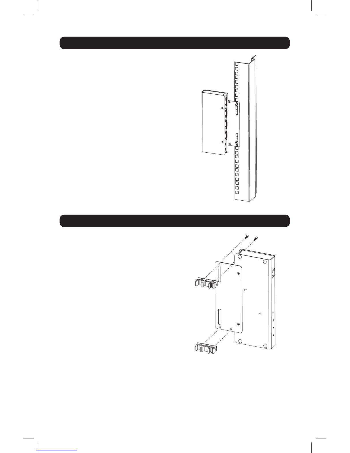
DIN Rail Mounting
To mount the B051-000 on a DIN rail:
1. Screw the mounting bracket to the
back of the B051-000 as described in
Steps 1 and 2 of the Rack Mounting
Section.
2. Use the larger screws supplied with the
rack-mount kit to screw the DIN rail
brackets to the mounting bracket as
shown in the diagram.
3. Hang the unit on the DIN rail.
Rack Mounting
Screw the bracket into any convenient
location on the rack.
Note: Rack screws are not provided. Use screws
that are appropriate for your rack.
17-11-282 93-373C.indd 5 12/5/2017 4:00:24 PM
Page 6
6
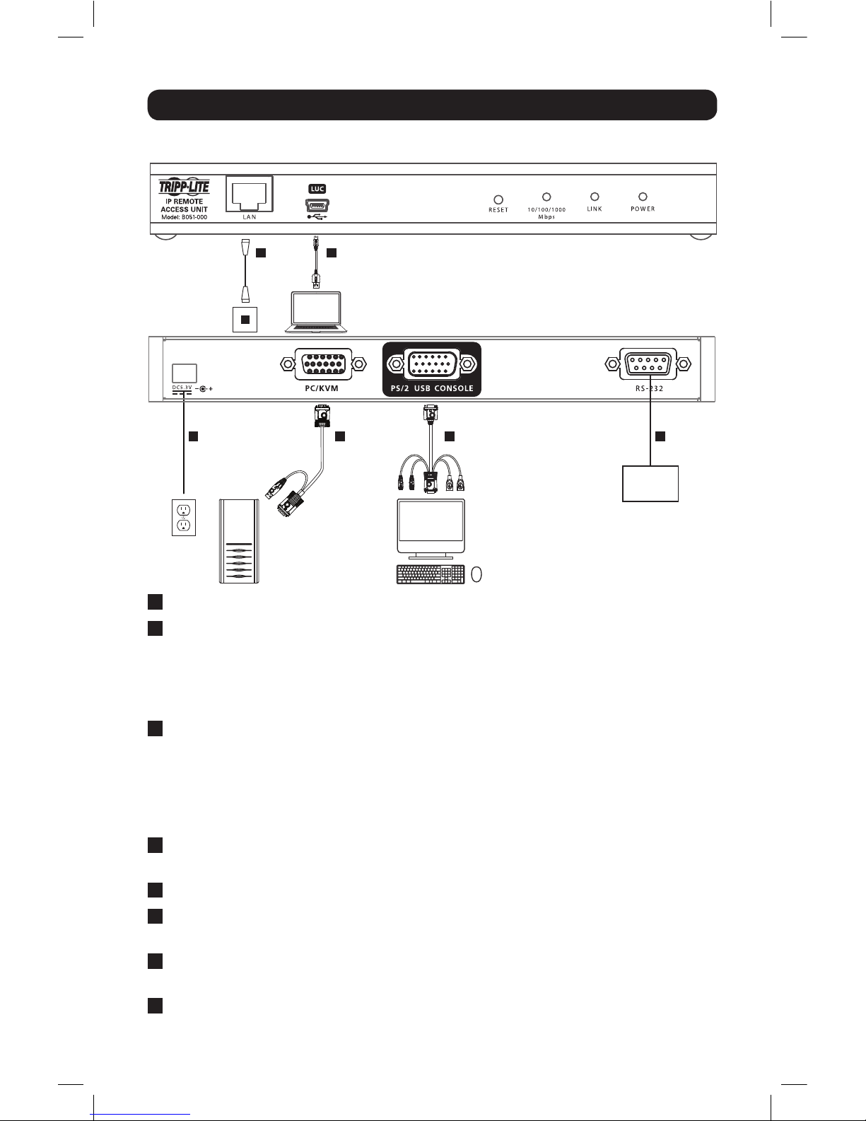
Installation
1
Make sure that power to all of the devices you will be connecting is turned off.
2
Using the included USB/PS2 Combo Console Cable kit, connect the PS/2 – USB
Console port on the unit to a VGA monitor, and a USB or PS/2 keyboard and
mouse.
Note: You can connect any combination of keyboard and mouse; USB and PS/2, USB and
USB, or PS/2 and PS/2.
3
Using either the USB or PS/2 KVM cable kits that came with the unit, connect
the PC/KVM port to the VGA monitor and USB or PS/2 keyboard/mouse ports to a
computer or KVM switch.
Note: The installation diagram shows a USB KVM cable kit. The PS/2 KVM cable kit is the
same, except it has (x2) PS/2 connectors to connect to the PS/2 ports on a computer or KVM
switch. Use the cable kit appropriate to your installation.
4
(Optional) Connect a modem or other RS-232 serial device to the unit’s RS-232
serial port.
5
Using a standard Cat5e/6 patch cable, connect the unit’s LAN port to your network.
6
Connect the included external power supply to the unit’s power jack, then plug it
into a Tripp Lite Surge Protector, UPS or PDU.
7
(Optional) When using the laptop USB console (LUC) feature, use the included
USB Mini-B cable to connect the unit’s LUC port to a USB port on a laptop.
8
Power on your installation, starting with the B051-000, then the computer or KVM
switch followed by any other connected devices.
Network Laptop
(USB, PS/2, KVM
or Computer)
(VGA Monitor and USB
or PS/2 Keyboard/Mouse)
Modem or
RS-232
Serial Device
5 7
23 46
Front Panel
Back Panel
17-11-282 93-373C.indd 6 12/5/2017 4:00:25 PM
Page 7

7
Laptop USB Console (LUC)
The unit’s front panel features a USB Mini-B port, which connects to the USB port on a
laptop, to provide console control of the unit. To use this feature, connect your laptop
to the LUC port on the front of the unit using a USB Mini-B cable. When connected,
an extra drive will appear in your computer’s “My Computer” screen. Click on this drive
to open the Windows and Java Non-Browser Clients. Run the desired client to access
the unit. The client’s login screen will appear, with the unit showing up as a USB Mass
Storage device in the Login Screen’s Server List. Highlight the unit, then connect per
the instructions in the Non-Browser Login section of this Quick Start Guide.
Administrator Setup
First Time Setup
Once the B051-000 has been installed, the Administrator must prepare the unit for
user operation by setting the network parameters and adding users.
Network Setup - IP Address Determination
Administrators logging in for the first time must access the B051-000 in order to
provide an IP address so users can connect. You can do this via Web Browser, the
IP Installer utility, or the non-browser Windows or Java Client applications.
Web Browser
By default, the B051-000 is set to have its IP address assigned automatically via
DHCP server. If it is connected to a network without a DHCP server, it boots with
a default IP address. On IPv4 networks, the default IP is 192.168.0.60. If it is on
an IPv6 network, the default IP address is determined by the B051-000’s MAC
address. For example, if the MAC address is 00-10-74-13-81-01, the IPv6 address is
FE80:0:0:0:0010:74FF:FE13:8101. The parts of the IP address that are in bold and
underlined are fixed.
1. Enter the unit’s IP address into your web browser.
2. You may be prompted by a screen stating that there is a problem with this website’s
security certificate. Click on the option to continue to the website anyway. (See
Web Browser Login section for details on installing the security certificate)
17-11-282 93-373C.indd 7 12/5/2017 4:00:25 PM
Page 8
8
Administrator Setup
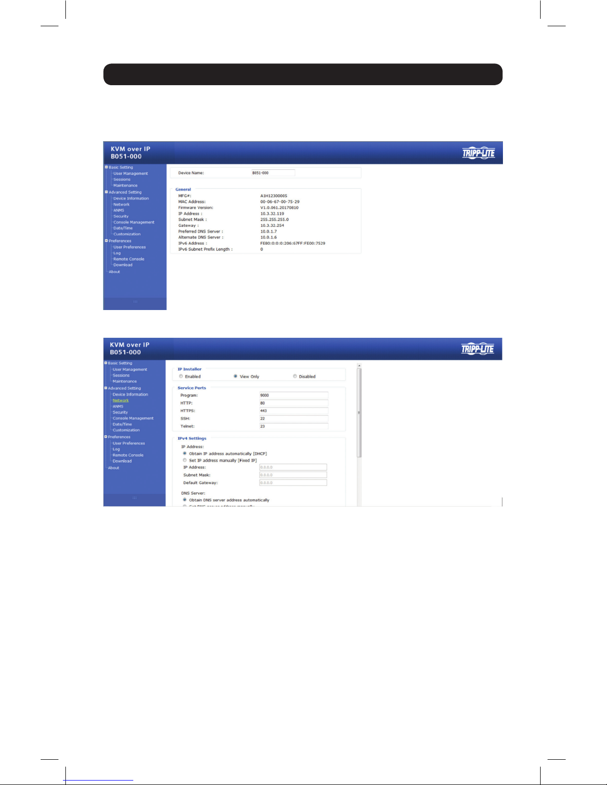
4. Click t he Network icon on the side of the page to open Network Settings.
5. By default, the Obtain IP address automatically [DHCP] checkbox is checked. To set
a fixed IP address, check the Set IP address manually [Fixed IP] check box in the
IPv4 or IPv6 settings section, depending on your network.
6. The IP Address, Subnet Mask and Default Gateway fields will be activated upon
checking the Set IP address manually [Fixed IP] checkbox. Fill in these fields with
information appropriate for your network.
3. You will be directed to a login page with Username and Password prompts. The
default Username is administrator and the default Password is password. The
Admin Utility Main Page will open upon entering the Username and Password.
17-11-282 93-373C.indd 8 12/5/2017 4:00:27 PM
Page 9

9
Administrator Setup
7. As with the IP Address settings, the DNS Server settings can be obtained
automatically or assigned manually. To manually enter these settings, check the
Set DNS server address manually checkbox and fill in the Preferred DNS server and
Alternate DNS server fields with information appropriate for your network. Note:
The Alternate DNS server field is optional.
8. When you have entered the IP Address and DNS Server settings, click the Apply
button. Clicking the Apply button will automatically check the Reset on exit
checkbox located in the Customization page of the Admin Utility. When you log out,
the unit will be reset and your network changes will be applied.
See Network Settings section in the Owner’s Manual for complete information on the
rest of the settings located in this page.
Non-Browser Client
The included CD contains Windows and Java Client applications that allow you to
remotely access the B051-000 and its Admin Utility without using a web browser.
The applications function is the same. However, the Windows Client is designed for
Windows computers, whereas the Java client is designed for either Windows or nonWindows computers. When accessed from a computer that is on the same network
as the IP remote access unit, the client will search the network for the device and
display it in a device list for you to access. If accessed from a computer that is not on
the same network as the IP remote access unit, you must obtain the IP address from
your network administrator and manually enter it into the client. (See Web Browser
section above for information on obtaining the IP address) To use the Windows or
Java client to assign a fixed IP address, follow the steps below.
1. Save the Windows or Java client from the CD to a desired location on your
computer. Double-click the file to open it.
2. When accessing the Windows Client for the first time, it will need to be installed
on your computer. Follow the installation prompts that appear. Once installed, a
Windows Client icon will appear on your desktop.
17-11-282 93-373C.indd 9 12/5/2017 4:00:27 PM
Page 10
10
Administrator Setup
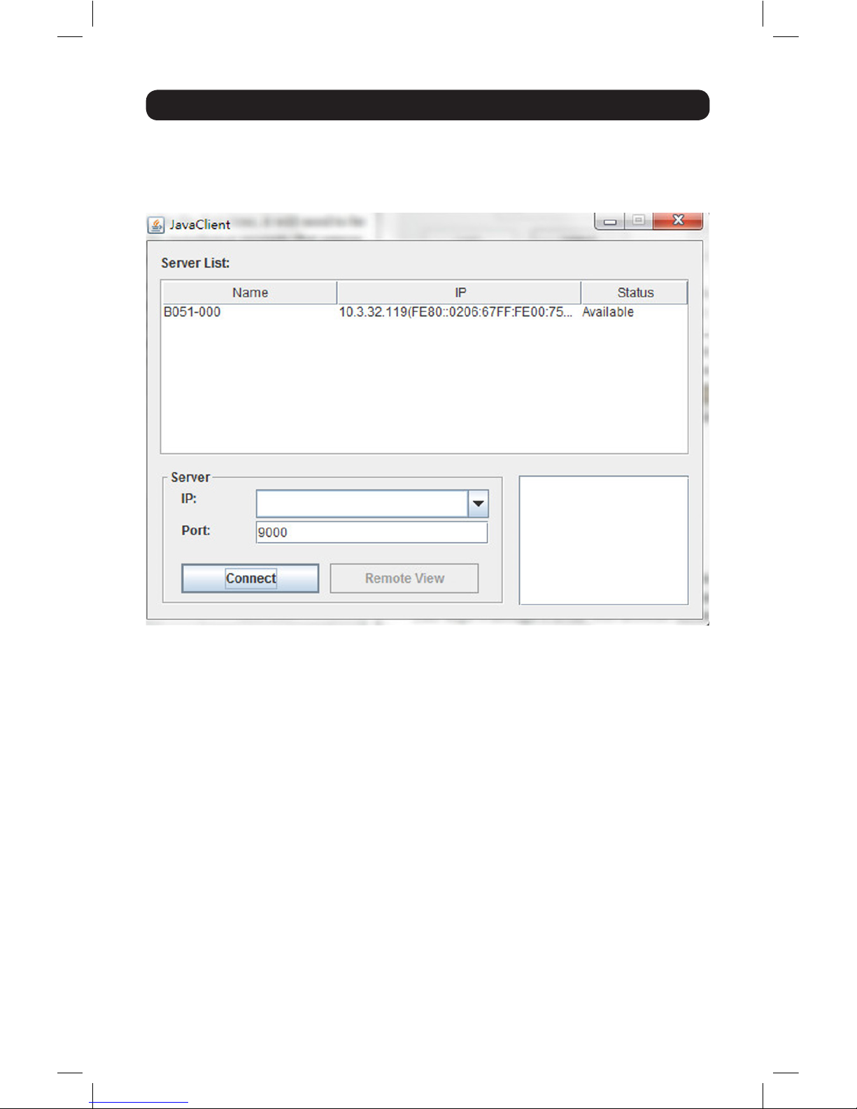
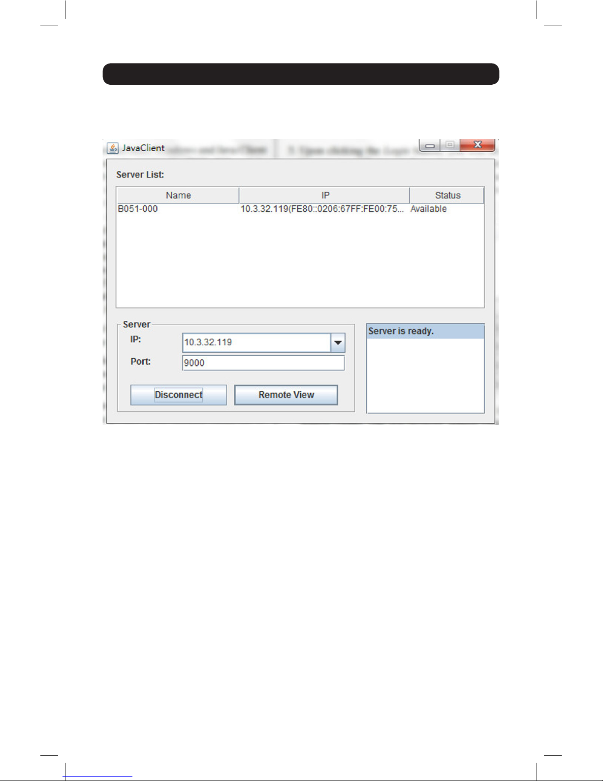
4. If you are on the same network as the B051-000, the client will locate and display
it in the Device List. In this case, highlight the unit in the device list and click
the Login button. If you are not on the same network as the unit, it will not be
displayed in the list. You must manually enter the IP address in the IP Address field,
then click the Connect button.
3. When accessing either the Windows or the Java client for the first time, you will be
prompted to enter the product serial number, which can be found on the CD. Once
entered, you will not be prompted for it again. The non-browser client connection
screen appears.
17-11-282 93-373C.indd 10 12/5/2017 4:00:27 PM
Page 11
11
Administrator Setup
5. Upon clicking the Connect button, you will be prompted to enter a Username and
Password. The default Username is administrator and the default Password is
password.
6. Click the Remote View button to initiate a remote session. Then, using the remote
tool bar at the top of the screen, click the Open GUI icon to open the unit’s
administrative interface. The non-browser interface contains most of the features
contained in the browser version, but are presented in a different format.
7. Click the Network tab on the left of the screen. From here, a fixed IP address can
be assigned in the same way as when using a web browser. (See steps 4 through 8
in the Web Browser section.)
17-11-282 93-373C.indd 11 12/5/2017 4:00:28 PM
Page 12
12
Administrator Setup
IP Installer
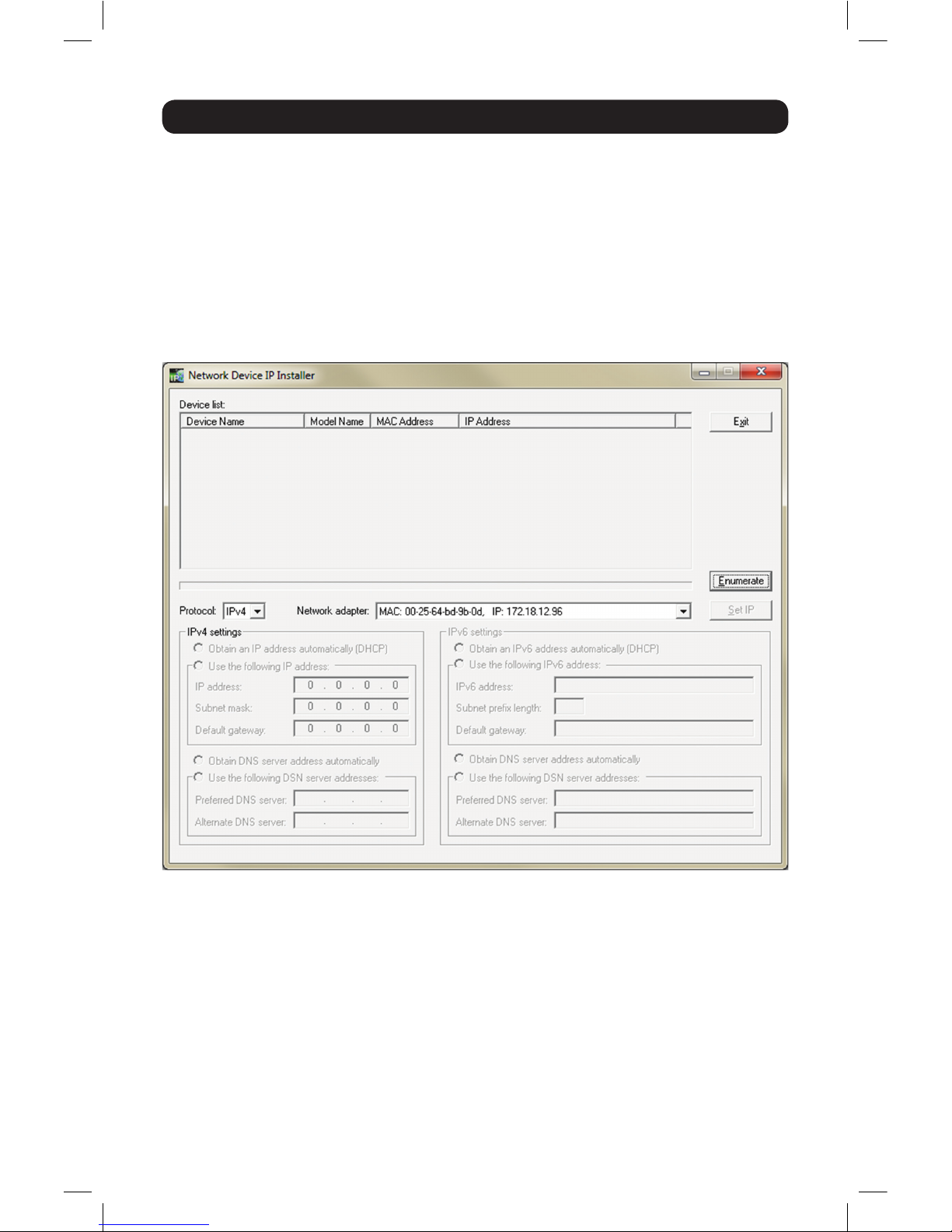
The included CD contains a Windows-based IP Installer utility that can be used
to obtain and edit the IP address. To use the IP Installer utility, the computer you
are using must be running a Windows operating system and must be on the same
network as the IP remote access unit. Also, the IP Installer setting in the Admin Utility
must be set to Enabled, which it is by default. (See the ANMS section in the Owner’s
Manual for details)
1. Save the IP Installer utility file to a desired location on your computer. Double-click
on the file to open the IP Installer utility.
2. Select the B051-000 from the Device List.
Note: If the list is empty or your device doesn’t appear, click the Enumerate button to refresh
the Device List. If there is more than one device in the list, use the MAC address on the
bottom of your unit to determine the desired device.
3. To assign a fixed IP address, check the Specify an IP address checkbox and
fill in the IP Address, Subnet Mask and Default Gateway fields with information
appropriate for your network.
4. Click t he Set IP button to apply the changes to the unit. The new IP address will
appear in the Device List.
5. Click the Exit button to exit the IP Installer utility.
17-11-282 93-373C.indd 12 12/5/2017 4:00:29 PM
Page 13

13
Logging In to the B051-000
The B051-000 IP remote access unit can be accessed in several ways: local console,
web browser, non-browser Windows or Java client. This section describes the login
procedures for each of these methods.
Local Console Login
When accessing the unit via local console, there is no login required except for what
is required to access the connected computer or KVM switch. The local keyboard,
monitor and mouse function the same as if they were connected directly to the
computer or KVM.
Web Browser Login
To log into the IP remote access unit via web browser, follow the steps below.
Note: Windows Vista and later users who intend to use the unit’s Virtual Media feature must
run Internet Explorer as an administrator. (See Virtual Media section in the Owner’s Manual for
details.)
1. Open your browser and enter the IP address of the B051-000 as given to you by
your system administrator.
Note: For security purposes, a login string may have been set by the administrator. If so, you
must include a forward slash and the login string following the IP address. For example, to
access a B051-000 with an IP address of 192.168.0.60 and a login string of B051000, you
would enter the URL as 192.168.0.60/B051000.
2. When logging in for the first time, a security alert appears to inform you that the
device’s certificate is not trusted, and asks if you want to proceed. The certificate
can be trusted, but the alert is triggered because the certificate’s name is not
found in the browser’s list of trusted certificates.
You have two options:
• If working on a computer other than your own, choose to proceed with your
session, even though the certificate is not trusted.
• If working on your own computer, install the certificate by following the steps
below.
Note: You may need to run Internet Explorer as an administrator to install the certificate.
a. In the Security Alert dialog box, click View Certificate. The certificate
information dialog box appears.
b. Click Install Certificate.
c. Follow the installation wizard to complete the certificate installation. The
default options are recommend.
d. When a caution screen appears asking you to confirm installing the certificate,
click Yes.
e. Click Finish to complete the installation and click OK to close the dialog box.
The certificate is now trusted.
17-11-282 93-373C.indd 13 12/5/2017 4:00:29 PM
Page 14

14
Logging In to the B051-000
You may continue to receive a security alert stating that the name on the security
certificate does not match the name attached to the website. Follow the steps
below to correct this issue.
a. In Internet Explorer, go to the Tools > Internet Options menu and click the
Advanced tab.
b. In the Settings list, scroll down and uncheck the Warn about certificate
address mismatch setting.
Note: In order for this setting to take effect, you must close out of and restart Internet
Explorer.
3. A login page appears asking you to enter a username and password. Enter in your
username and password as given to you by your system administrator. If you are an
administrator logging in for the first time, the default username is administrator and
the default password is password.
Non-Browser Login
The included CD contains Windows and Java Client applications that allow you to
remotely access the B051-000 and its Admin Utility without using a web browser.
The applications function is the same. However, the Windows Client is designed
for Windows computers, whereas the Java client is designed for either Windows or
non-Windows computers. If you do not have access to the CD, obtain a copy of the
Windows and/or Java Client from your system administrator.
1. Save the Windows or Java client to a desired location on your computer. Doubleclick on the file to open it.
2. When accessing the Windows Client for the first time, it will need to be installed
on your computer. Follow the installation prompts that appear. Once installed, a
Windows Client icon will appear on your desktop.
3. When accessing either the Windows or the Java client for the first time, you will
be prompted to enter the product serial number, which can be found on the CD.
If you do not have access to the CD, obtain the serial number from your system
administrator. Once entered, you will not be prompted for it again. The non-browser
client connection screen appears.
17-11-282 93-373C.indd 14 12/5/2017 4:00:29 PM
Page 15
15
Logging In to the B051-000
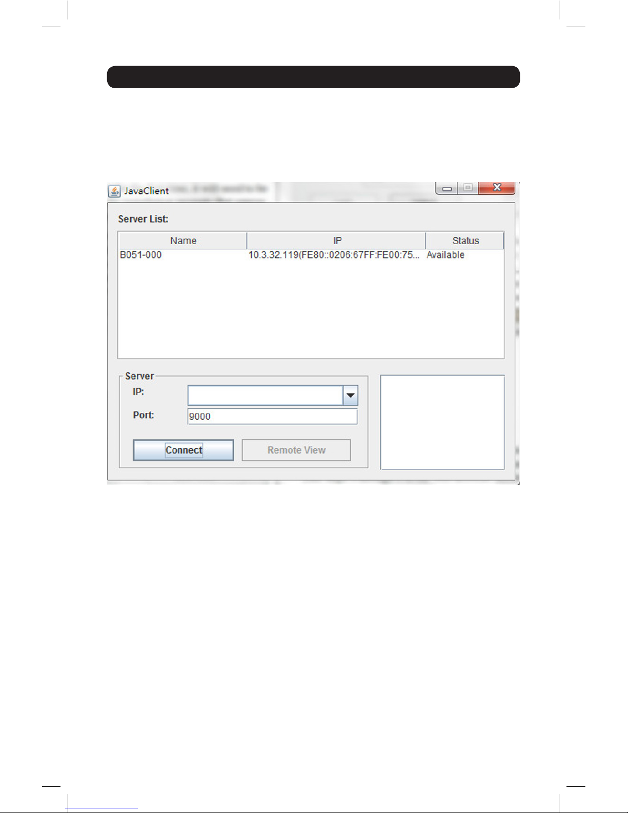
4. If you are on the same network as the B051-000, the client will locate and display
it in the Device List. In this case, highlight the unit in the device list and click
the Connect button. If you are not on the same network as the unit, it will not
be displayed in the list. You must manually enter the IP address, as given to you
by your system administrator, in the IP Address field, and then click the Connect
button.
5. Upon clicking the Connect button, you will be prompted to enter a Username and
Password. Enter your username and password as given to you by your system
administrator. If you are an administrator logging in for the first time, the default
username is administrator, and the default password is password. Click the Remote
View button to initiate a remote session.
17-11-282 93-373C.indd 15 12/5/2017 4:00:29 PM
Page 16

16
Warranty and Product Registration
3-YEAR LIMITED WARRANTY
Seller warrants this product, if used in accordance with all applicable instr uctions, to be free from original defects in material
and workmanship for a period of 3 years from the date of initial purchase. If the product should prove defective in material or
workmanship within that period, Seller will repair or replace the product, in its sole discretion. Service under this Warranty can
only be obtained by your delivering or shipping the product (with all shipping or delivery charges prepaid) to: Tripp Lite;
1111 W. 35th Street; Chicago IL 60609; USA. Seller will pay return shipping charges. Visit w ww.tripplite.com/support before
sending any equipment back for repair.
THIS WARRANTY DOES NOT APPLY TO NORMAL WEAR OR TO DAMAGE RESULTING FROM ACCIDENT, MISUSE, ABUSE
OR NEGLECT. SELLER MAKES NO EXPRESS WARRANTIES OTHER THAN THE WARR ANTY E XPRESSLY SET FORTH HEREIN.
EXCEPT TO THE EX TENT PROHIBITED BY APPLICABLE LAW, ALL IMPLIED WARRANTIES, INCLUDING ALL WARRANTIES OF
MERCHANTABILIT Y OR FITNESS, ARE LIMITED IN DURATION TO THE WARRANTY PERIOD SET FORTH ABOVE; AND THIS
WARRANTY EXPRESSLY EXCLUDES ALL INCIDENTAL AND CONSEQUENTIAL DAMAGES. (Some states do not allow limitations
on how long an implied warranty lasts, and some states do not allow the exclusion or limitation of incidental or consequential
damages, so the above limitations or exclusions may not apply to you. This Warranty gives you specific legal rights, and you
may have other rights which vary from jurisdiction to jurisdiction).
Tripp Lite; 1111 W. 35th Street; Chicago IL 60609; USA
WARNING: The individual user should take care to determine prior to use whether this device is suitable, adequate or safe for
the use intended. Since individual applications are subject to great variation, the manufacturer makes no representation or
warranty as to the suitabilit y or fitness of these devices for any specif ic application.
PRODUCT REGISTRATION
Visit w ww.tripplite.com/warranty today to register your new Tripp Lite product. You’ll be automatically entered into a drawing
for a chance to win a FREE Tripp Lite product!*
* No purchase neces sary. Void where prohibited. Some restrictions apply. See website for details.
FCC Part 68 Notice (United States Only)
If your Modem/Fax Protection causes harm to the telephone network, the telephone company may temporarily discontinue
your service. If possible, they will notify you in advance. If advance notice isn’t practical, you will be notified as soon as
possible. You will be advised of your right to file a complaint with the FCC. Your telephone company may make changes in
its facilities, equipment, operations or procedures that could affect the proper operation of your equipment. If it does, you
will be given advance notice to give you an opportunit y to maintain uninterrupted service. If you experience trouble with this
equipment’s Modem/Fax Protection, please visit www.tripplite.com/support for repair/warranty information. The telephone
company may ask you to disconnect this equipment from the network until the problem has been corrected or you are sure
the equipment is not malfunctioning. There are no repairs that can be made by the customer to the Modem/Fax Protection.
This equipment may not be used on coin service provided by the telephone company. Connection to party lines is subject to
state tariffs. (Contact your state public utility commission or corporation commission for information.)
WEEE Compliance Information for Tripp Lite Customers and Recyclers (European Union)
Under the Waste Electrical and Electronic Equipment ( WEEE) Directive and implementing regulations, when
customers buy new electrical and electronic equipment from Tripp Lite they are entitled to:
• Send old equipment for recycling on a one-for-one, like-for-like basis (this varies depending on the country)
• Send the new equipment back for recycling when this ultimately becomes waste
Warning!
Use of this equipment in life suppor t applications where failure of this equipment can reasonably be expected to cause the
failure of the life support equipment or to significantly affect its safety or effectiveness is not recommended.
Tripp Lite has a policy of continuous improvement. Product specifications are subject to change without notice.
17-11-28 2 93-3 73C _ Re vB
1111 W. 35th Street, Chicago, IL 60609 USA • www.tripplite.com/support
17-11-282 93-373C.indd 16 12/5/2017 4:00:29 PM
 Loading...