

Page 1
WARRANTY
REGISTRATION:
register online today for a
chance to win a FREE Tripp Lite
product—www.tripplite.com/warranty
Safety
1111 W. 35th Street Chicago, IL 60609 USA
Customer Support: (773) 869-1234
www.tripplite.com
Français: p.5 Español: p.9
isobar
®
Digital IR-Remote
Capable Power
Conditioning
Center
Model: HT7300PC
Owner's Manual
High Definition
(HD) Compatible!
IMPORTANT SAFETY INSTRUCTIONS.
SAVE THESE INSTRUCTIONS.
This manual contains instructions and warnings that should be followed during the
installation and operation of all Tripp Lite Power Conditioning Centers. Failure to
heed these warnings will void your warranty.
• The Power Conditioning Center features an internal protection that will disconnect
the surge-protective component at the end of its useful life but will maintain power
to the load—now unprotected.
• Do not connect the Power Conditioning Center to an ungrounded outlet. Do not use
with 2-wire extension cords or adapters. Do not plug extension cords into the Power
Conditioning Center.
Features
A
B
C
D
E
F
G
H
I
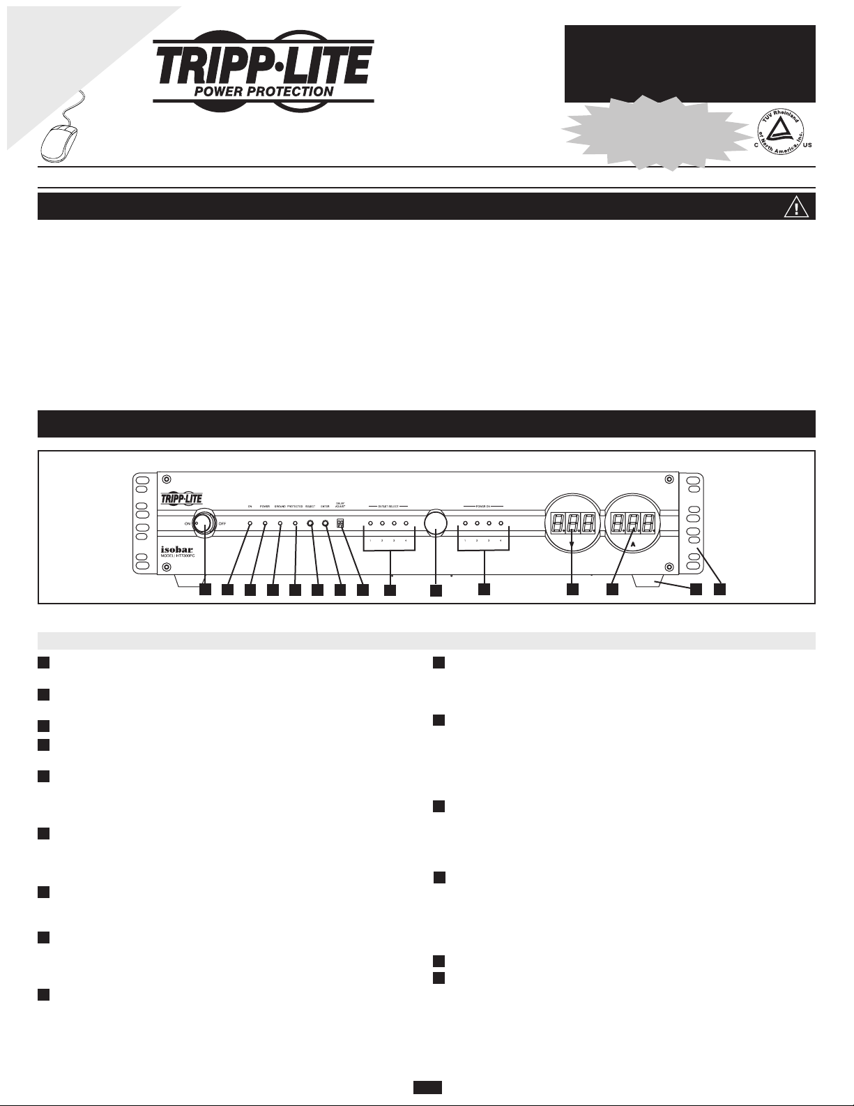
Front Panel
• The Power Conditioning Center is designed for indoor use only. Install the Power
Conditioning Center away from heat-emitting appliances such as radiators or heat
registers. Do not install where excessive moisture is present.
• Never install electrical, telephone, network or coaxial wiring during a lightning
storm.
• Do not drill into any part of the housing or open the housing for any reason. There
are no user-serviceable parts inside.
O
M
K
J
L
N
Front Panel
A
Illuminated “ON/OFF” Power Switch: turns power on and off at all of the
outlets.
B
“ON” LED: indicates that AC power is available at the Power Conditioning
Center's outlets. This LED will illuminate when the Power Switch is set to “ON”.
C
“POWER” LED: indicates AC power is available at the wall outlet.
“GROUND” LED: indicates wall outlet is grounded and surge protection can
D
properly function.
“PROTECTED” LED: indicates the surge suppression components are intact
E
and providing complete protection against surges. If this LED does not illuminate,
some of the surge suppression components are not functioning, and the unit should
be replaced. Call Tripp Lite Customer Support at (773) 869-1234.
F
“SELECT” Switch: selects controllable IR outlets (labeled “IR1”, “IR2”, “IR3”
and “IR4” on the rear panel of the Power Conditioning Center) to be turned on or
off using the “ENTER” Switch. See “IR Outlet Control” in the “Optional
Installation” section for setting procedure.
G
“ENTER” Switch: turns controllable IR outlets on or off (after they have first
been selected using the “SELECT” Switch). See “IR Outlet Control” in the
“Optional Installation” section for setting procedure.
“DELAY/ADJUST” DIP Switches: select the delay interval (0, 1, 10 or 30
H
seconds) when turning on or off multiple IR outlets in a sequence using a remote.
See “IR Outlet Control” in the “Optional Installation” section for setting
procedure.
I
“OUTLET SELECT” LEDs: indicate which controllable IR outlets (labeled
“IR1”, “IR2”, “IR3” and “IR4” on the rear panel of the Power Conditioning
Center) have been selected using the “SELECT” Switch. Each LED will flash
when its corresponding IR outlet has been selected. Each LED will illuminate
continuously when power has been turned on at the outlet.
“POWER ON” LEDs: indicate which controllable IR outlets have been turned
J
ON using the “ENTER” Switch. Each LED will flash when its corresponding IR
outlet has been selected. Each LED will illuminate continuously when power has
been turned on at the outlet.
Infrared (IR) Sensor: is for use with either the included IR remote or a universal
K
learning IR remote (user-supplied)* to control IR outlets. Program the outlets to
turn on or off individually or in a sequence. If the sensor is covered, a remote IR
sensor (user-supplied) can be connected to the IR sensor input on the rear panel of
the Power Conditioning Center.
* The user-supplied remote must be a universal learning type to work with the included remote.
“Input Voltage” Digital LED Display: clearly shows voltage variations of
L
incoming utility power. The Power Conditioning Center can alert you to abnormal
voltage, but cannot regulate it. If persistent low or high voltage conditions
continually affect equipment performance, consider purchasing a Tripp Lite UPS
system or line conditioner.
“Current Usage” LED Display: allows you to get the maximum use from your
M
Power Conditioning Center by showing you the total amperage load of all of your
connected components. CAUTION: the total amperage capacity of the Power
Conditioning Center is 15 amps. Any amperage loads that exceed 15 amps will
cause the circuit breaker to trip. Action should be taken to reduce connected load
and reset the circuit breaker.
N
Rackmount Hardware: allows 2U mounting in standard sized racks.
O
Removeable Console Feet: allow placement on a shelf as a console component
within a system. Unscrew feet prior to rackmounting the Power Conditioning
Center.
1
Page 2
Features
continued
P
R
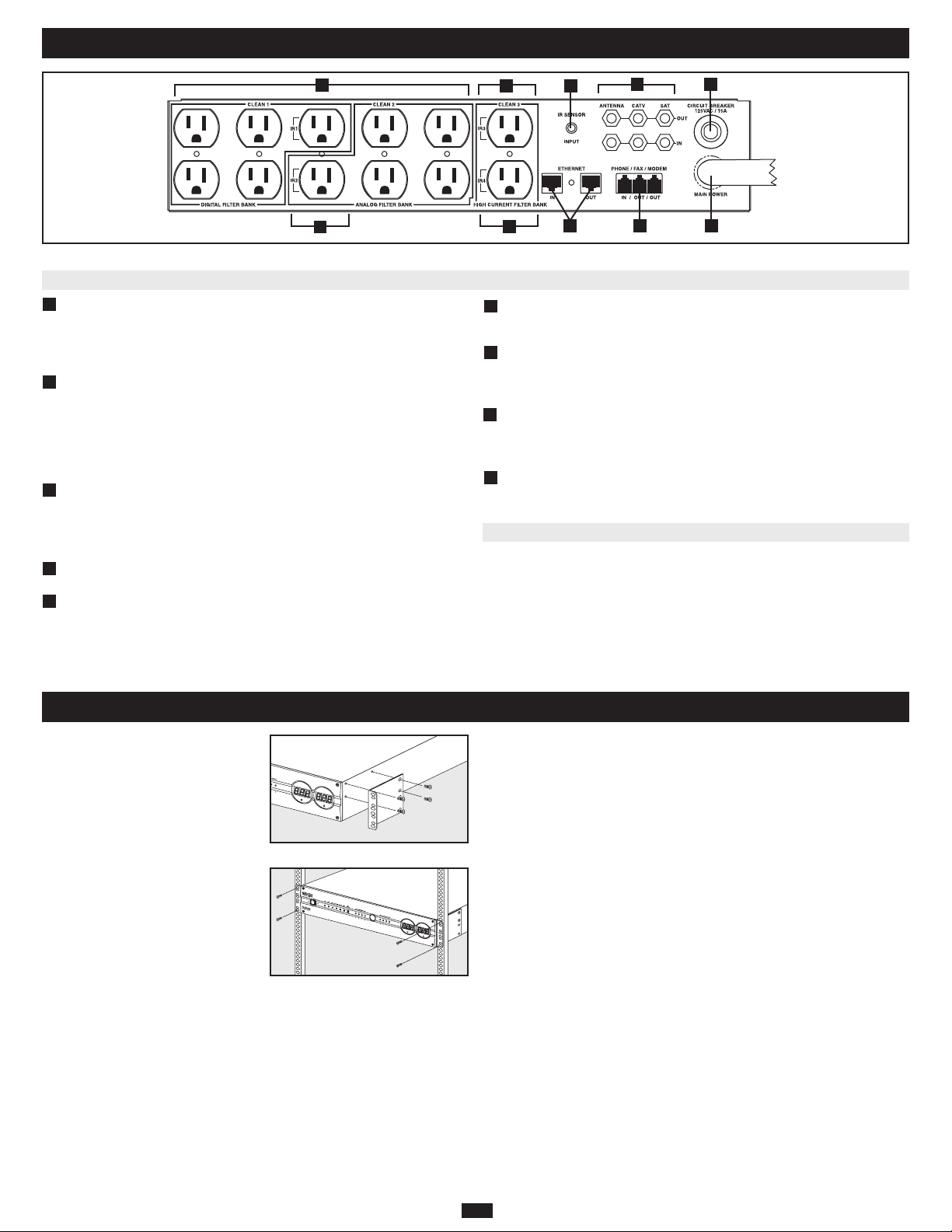
Rear Panel
“Digital” and “Analog” Isolated Filter Banks: are designed to protect digital
P
and analog equipment against surge damage and line noise distortion. State-of-theart Isobar®technology provides an additional level of line noise filtering: ensuring
line noise generated by equipment connected to one filter bank does not interfere
with the performance of equipment connected to another filter bank.
Q
“High Current” Isolated Filter Bank: will not limit or impede current, providing
equipment such as amplifiers and subwoofers with the high amperage current they
need for ultimate audio performance. This filter bank protects high-current
equipment against surge damage and line noise distortion. State-of-the-art Isobar
technology provides an additional level of line noise filtering: ensuring line noise
generated by equipment connected to one filter bank does not interfere with the
performance of equipment connected to another filter bank.
“IR” Outlets: can be controlled either manually (using front panel switches) or
R
remotely using the included IR remote or a universal learning IR remote (usersupplied)*. Program the outlets to turn on or off individually or in a sequence. See
“IR Outlet Control” in the “Optional Installation” section for details.
* The user-supplied remote must be a universal learning type to work with the included remote.
Infrared (IR) Sensor Input: accepts a remote IR sensor (user-supplied), for use
S
when the built-in front panel IR sensor is covered.
3-Line High-Definition (HD) Compatible Coax Protection: includes three sets
T
of gold coaxial “F” connectors that protect components against surge damage and
line noise distortion on three DSS satellite, cable or antenna lines simultaneously.
Coaxial protection is compatible with all digital signals for High-Definition (HD)
video.
W
X
Rear Panel
Q
R
1-Line Ethernet Protection: safeguards equipment against surge damage and line
U
S
U
T
V
noise distortion on a 10/100 Base T network line.*
* Not compatible with PoE (Power Over Ethernet) applications.
1-Line Tel/Modem Protection: safeguards Personal Video Recorders (TiVo®) and
V
other components against surge damage and line noise distortion on a single dialup line. Built-in splitter (one jack in and two jacks out) allows you to
simultaneously connect and protect two components sharing a single line.
W
Circuit Breaker: protects against dangerous system overload. If the total load on
®
the Power Conditioning Center's outlets exceeds 15 amps, the circuit breaker will
trip and power will be turned off at all outlets. Reduce the load by unplugging
some devices. Press the circuit breaker in to restore power.
X
10 ft. Cord and Right Angle Plug: right angle plug allows equipment and
furniture to be flush against the wall. Connect to a standard 3-wire grounded 120V
AC, 60 Hz. wall outlet.
Not Shown
Unit/Cord Labels: coordinate Power Conditioning Center outlets with component
power cords for easy identification.
Audible Alarm: immediately alerts you to damaged internal protection circuitry. If
this occurs, contact Tripp Lite Customer Support.
Installation
STEP 1) Place Your Power Conditioning
Center in a Console or Mount It in a
Rack: The Power Conditioning Center
includes rubber mounting feet as well as
rackmount hardware. Place the Power
Conditioning Center on a shelf as a console
component or use the rackmount hardware
to mount it in any standard size rack.
To mount the unit in a rack, first remove
the console feet by unscrewing them.
Attach the included rackmount hardware
to the sides of the Power Conditioning
Center (STEP 1A) with the included
screws. After installing the hardware,
install four user-supplied rackmount
screws through the unit's rackmount
hardware (STEP 1B) and into the rack rails
as shown. The user must determine the
fitness of the user-supplied screws prior to installation.
STEP 2) Connect Your Power Conditioning Center to the AC Power Line: Plug
the Power Conditioning Center's power cord into a standard, 3-wire grounded 120V
AC, 60 Hz. outlet.
STEP 3) Turn Your Power Conditioning Center ON: Press the Power Conditioning
Center's power switch until it illuminates, indicating power is supplied at the Power
Conditioning Center's outlets.
STEP 4) Check Your Power Conditioning Center's Diagnostic Indicator Lights:
Check the LEDs prior to connecting your equipment. They will indicate various
operating conditions when the Power Conditioning Center is plugged into a live 120V
AC outlet and the Power Conditioning Center's power switch is on.
Step 1A
Step 1B
STEP 5) Connect Your Equipment to the Power Conditioning Center's AC
Outlets: Plug your equipment's power cords (including 2-wire devices) into the
Power Conditioning Center's AC outlets. DO NOT plug in extension cords. DO NOT
OVERLOAD the Power Conditioning Center's outlets. The Power Conditioning
Center can accommodate a total equipment load of up to 15 amps (whether plugged
into a single outlet or spread out over multiple outlets). If the load on the Power
Conditioning Center's outlets exceeds 15 amps, the circuit breaker will trip and power
will be turned off at all outlets. Reduce the load by unplugging some devices. Press
the circuit breaker to restore power.
Isolated Filter Banks: Depending on the type of equipment you are connecting,
choose one of three Isolated Filter Banks (see Rear Panel diagram in “Features”
section) that provide an extra level of filtering between components:
• Connect digital equipment to the five outlets labeled “Digital Filter Bank”.
• Connect analog equipment to the five outlets labeled “Analog Filter Bank”.
• Connect equipment with high amperage current draw (such as amplifiers and
subwoofers) to the two outlets labeled “High Current Filter Bank”. These outlets
will not limit or impede current, providing equipment with the high amperage
current they need for ultimate audio performance.
IR Outlets: Outlets labeled “IR1”, “IR2”, “IR3” and “IR4” can be controlled either
manually (using front panel switches) or remotely using the included IR remote or a
universal learning IR remote (user-supplied)*. NOTE: remote control is optional; IR
Outlets will function the same as other outlets until you attempt to control them either
manually or remotely. See “IR Outlet Control” in the “Optional Installation” section
for details.
* The user-supplied remote must be a universal learning type to work with the included remote.
2
Page 3

Optional Installation
Tel/Modem, Ethernet and Coaxial Connections
Connect Your Equipment to the Power Conditioning Center's Tel/Modem Jacks:
Connect a phone cable from the wall jack directly to the Power Conditioning Center's
RJ-style phone jack labeled “IN.” Connect a phone cable from the Power
Conditioning Center's RJ-style phone jack labeled "OUT" directly to the device to be
protected. HT7300PC models feature two “OUT” jacks; either one or both of the jacks
may be used, but protection is for a device or devices sharing a single line only. The
Power Conditioning Center must always be the first item connected in line from the
wall jack. The Power Conditioning Center must be plugged into a 3-wire, grounded
AC outlet for phone line surge protection to work.
Connect Your Equipment to the Surge Suppressor's Network Jacks:* Connect a
data cord from the wall jack or cable/DSL modem directly to the Power Conditioning
Center's network jack labeled “IN.” Connect a data cord from the Power Conditioning
Center's network jack labeled “OUT” directly to the device to be protected. The
Power Conditioning Center must always be the first item connected in line from the
Ethernet source (typically a wall jack). The Power Conditioning Center must be
plugged into a 3-wire grounded AC outlet for network line surge protection to work.
* 10/100 BaseT/TX, Token Ring. Not compatible with PoE (Power Over Ethernet) applications
Connect Your Equipment to the Power Conditioning Center's Coaxial Jacks:
Connect a coaxial cable from the wall jack directly to the Power Conditioning
Center's “F” style coaxial jack labeled “IN.” Connect a coaxial cable from the Power
Conditioning Center's “F” style coaxial jack labeled “OUT” directly to the device to
be connected. Additional sets of coaxial jacks allow for simultaneous connection and
protection of additional devices on additional lines (cable, antenna or satellite). Make
sure that each device and its corresponding wall jack are connected to corresponding
“IN” and “OUT” jacks on the Power Conditioning Center. The Power Conditioning
Center must always be the first item connected in line from the coaxial wall jack. The
Power Conditioning Center must be plugged into a 3-wire grounded AC outlet for
coaxial line surge protection to work. Make sure coax cables connected to satellite
dishes, antennas, etc. are also grounded.
IR Outlet Control
Manual Control
Turn Controllable IR Outlets ON or OFF
• STEP 1: Momentarily press the “SELECT” Switch to choose which IR outlet you
wish to select. The corresponding “OUTLET SELECT” LED will flash to
indicate which outlet you have selected. Each time you press the switch, it will
select the next LED in line.
• STEP 2: To turn IR outlet ON: When an outlet is selected using the “SELECT”
Switch, momentarily press the "ENTER" Switch to turn the outlet ON. The
corresponding “POWER ON” LED will illuminate to indicate power is ON at the
outlet. The corresponding “OUTLET SELECT” LED will illuminate
continuously to indicate the outlet is no longer selected. To turn IR outlet OFF:
Momentarily press the “SELECT” Switch to choose which IR outlet you wish to
turn off. The corresponding “OUTLET SELECT” LED will flash to indicate
which outlet you have selected. Momentarily press the “ENTER” Switch to turn
the outlet OFF. The corresponding “POWER ON” LED will go off to indicate
power is OFF at the outlet. The corresponding “OUTLET SELECT” LED will
also go off.
Set Delay Interval for Remote IR Outlet Power ON or Power OFF
Using a small tool, set the DIP switches to select the delay interval (0, 1, 10 or 30
seconds) when turning on or off multiple IR outlets in a sequence using a remote. See
chart for settings.
Delay Interval Position Position
0 seconds DOWN DOWN
1 second
10 seconds DOWN UP
30 seconds UP UP
(Factory Setting) UP DOWN
DIP Switch 1 DIP Switch 2
Remote Control (With Included IR Remote)
All remotes require unobstructed access to the IR sensor located
on the front panel of the Power Conditioning Center.
Turn All Controllable IR Outlets ON
Momentarily press the remote’s “ALL ON” button, and then
press the “ENTER” button. The IR Outlets will turn ON in the
following sequence: 1, 2, 3, 4.
Turn All Controllable IR Outlets OFF
Momentarily press the remote’s “ALL OFF” button, and then
press the “ENTER” button. The IR Outlets will turn OFF in the
following sequence: 4, 3, 2, 1.
Turn Individual Controllable IR Outlets ON or OFF
Momentarily press the number button on the remote (1, 2, 3 or
4) that corresponds to the IR Outlet you wish to control, and then
press the "ENTER” button.
Remote Control
(With User-Supplied Universal Learning IR Remote)
Use the included IR remote to program a user-supplied universal learning IR remote.*
Follow the programming instructions for the user-supplied remote. All remotes
require unobstructed access to the IR sensor located on the front panel of the Power
Conditioning Center.
* The user-supplied remote must be a universal learning type to work with the included remote.
3
Page 4

Troubleshooting
Before calling Tripp Lite for technical assistance, try the possible solutions to common problems listed below. If you still require assistance, call Tripp Lite Customer Service
at (773) 869-1234.
Problem
No AC output power available at
outlets.
Possible Solutions
Check Connections: Ensure the power cord is properly connected to a live 120V AC wall outlet.
Check Outlet Status: Ensure that you haven't inadvertently turned the IR outlets off using the Power Conditioning Center’s
switches or a remote.
Reset Circuit Breaker: Reduce equipment load by unplugging some devices. Press the circuit breaker in to restore power.
IR outlets do not turn on or off in
Reset the Power Conditioning Center: Use the Power Switch to turn the Power Conditioning Center off and then on to reset.
sequence properly.
Included IR remote does not control
the IR outlets.
Clear Access to IR Sensor: Ensure the remote is pointed directly (with no obstruction) at the IR sensor located on the front panel
of the Power Conditioning Center.
Reprogram Included IR Remote: The included remote is preprogrammed, but may need to be reprogrammed if it does not
control the IR outlets properly.
• STEP 1: Press and hold the “ENTER” button located on the front panel of the Power Conditioning Center for at least 5
seconds (the “OUTLET SELECT” LEDs will rapidly flash to indicate the interval has passed). The Power Conditioning
Center will be in Learning Mode.
Note: you will have 15 seconds to complete STEP 2; otherwise, the Power Conditioning Center will revert back to Normal Mode, and you will need to start the
progamming process over.
• STEP 2: Point the included IR remote at the IR sensor located on the front panel of the Power Conditioning
Center. Momentarily press any of the number buttons on the remote (1, 2, 3 or 4), and then press the remote’s “ENTER”
button. If the programming procedure is successful, the Power Conditioning Center's “OUTLET SELECT” LEDs will rapidly
flash. The remote is now reprogrammed and ready for use.
FCC Part 68 Notice (United States Only)
If your Modem/Fax Protection causes harm to the telephone network, the telephone company may temporarily
discontinue your service. If possible, they will notify you in advance. If advance notice isn't practical, you will be
notified as soon as possible. You will be advised of your right to file a complaint with the FCC. Your telephone
company may make changes in its facilities, equipment, operations or procedures that could affect the proper
operation of your equipment. If it does, you will be given advance notice to give you an opportunity to maintain
uninterrupted service. If you experience trouble with this equipment's Modem/Fax Protection, please call Tripp
Lite Technical Support at (773) 869-1234 for repair/warranty information.The telephone company may ask you to
disconnect this equipment from the network until the problem has been corrected or you are sure the equipment
is not malfunctioning. There are no repairs that can be made by the customer to the Modem/Fax Protection.This
equipment may not be used on coin service provided by the telephone company. Connection to party lines is
subject to state tariffs. (Contact your state public utility commission or corporation commission for information.)
Lifetime Limited Warranty
Seller warrants this product, if used in accordance with all applicable instructions, to be free from original defects
in material and workmanship for its lifetime. If the product should prove defective in material or workmanship
within that period, Seller will repair or replace the product, in its sole discretion. Service under this Warranty can
only be obtained by your delivering or shipping the product (with all shipping or delivery charges prepaid) to:Tripp
Lite, 1111 W. 35th St., Chicago, IL 60609. Seller will pay return shipping charges The warranties of all TRIPP
LITE surge suppressors are null and void if they have been connected to the output of any UPS system. The
warranties of all TRIPP LITE UPS Systems are null and void if a surge suppressor has been connected to its
output receptacles.
THIS WARRANTY DOES NOT APPLY TO NORMAL WEAR OR TO DAMAGE RESULTING FROM ACCIDENT,
MISUSE, ABUSE OR NEGLECT. SELLER MAKES NO EXPRESS WARRANTIES OTHER THAN THE
WARRANTY EXPRESSLY SET FORTH HEREIN. EXCEPT TO THE EXTENT PROHIBITED BY APPLICABLE
LAW, ALL IMPLIED WARRANTIES, INCLUDING ALLWARRANTIES OF MERCHANTABILITY OR FITNESS,
ARE LIMITED IN DURATION TO THE WARRANTY PERIOD SET FORTH ABOVE; AND THIS WARRANTY
EXPRESSLY EXCLUDES ALL INCIDENTAL AND CONSEQUENTIAL DAMAGES. (Some states do not allow
limitations on how long an implied warranty lasts, and some states do not allow the exclusion or limitation of
incidental or consequential damages, so the above limitations or exclusions may not apply to you. This Warranty
gives you specific legal rights, and you may have other rights which vary from jurisdiction to jurisdiction.) TRIPP
LITE; 1111 35th St.; Chicago, IL 60609
WARNING: The individual user should take care to determine prior to use whether this device is suitable,
adequate or safe for the use intended. Since individual applications are subject to great variation, the
manufacturer makes no representation or warranty as to the suitability or fitness of these devices for any specific
application.
Tripp Lite has a policy of continuous improvement. Specifications are subject to change without notice.
WARRANTY REGISTRATION
Visit www.tripplite.com/warranty today to register the warranty for your new Tripp Lite product. You'll be
automatically entered into a drawing for a chance to win a FREE Tripp Lite product!*
* No purchase necessary.Void where prohibited. Some restrictions apply. See website for details.
Regulatory Compliance Identification Numbers
For the purpose of regulatory compliance certifications and identification, your Tripp Lite product has been
assigned a unique series number. The series number can be found on the product nameplate label, along with
all required approval markings and information. When requesting compliance information for this product, always
refer to the series number.The series number should not be confused with the marking name or model number of
the product.
Ultimate Lifetime Insurance Policy
(This is a limited warranty valid in the U.S. and Canada only.)
Tripp Lite warrants, for the lifetime of the product, (at Tripp Lite's option) to repair or replace (on a pro rata basis)
directly connected equipment that is damaged due to power transients while properly connected to Tripp Lite
products offering the Ultimate Lifetime Insurance Policy. Power transients include spikes and surges on the AC
power, data or telephone lines that the Tripp Lite products have been designed to protect against (as recognized
by industry standards). The following four paragraphs are conditions that must be complied with before the
warranty becomes valid; failure to comply with these requirements will void the warranty.
AC Power Line Transients: To claim damages, the Tripp Lite product must be plugged into a properly wired and
grounded outlet. No extension cords or other electrical connections may be used.The installation must comply
with all applicable electrical and safety codes set forth by the National Electrical Code (NEC). Except as provided
above, this warranty does not cover any damage to properly connected electronic equipment resulting from a
cause other than an "AC power transient". If user meets all of the above requirements, Tripp Lite will repair or
replace (at Tripp Lite's option) equipment up to the specified value (See Ultimate Lifetime Insurance Policy Limits).
No coverage is allowed for damage entering from telephone or data lines, unless they are separately protected,
as described below.
Telephone and Data Line Transients: Tripp Lite will repair or replace directly connected equipment that is
damaged by transients on telephone and/or data lines only when all such paths are protected by a Tripp Lite
protection product(s) and the AC power (utility) line is simultaneously protected by a Tripp Lite power protection
device (UPS, surge suppressor or line conditioner) with Ultimate Lifetime Insurance coverage. Additional
telephone and/or data line connected devices downstream must have their own telephone and/or dataline
protectors.
Reimbursement dollar limits will be equal to that of the Tr ipp Lite power protection protector. Coverage is excluded
where a suitable environment for the protection device is not provided, including, but not limited to, lack of a
proper safety ground.Telephone service equipment must also include a properly installed and operating "primary
protection" device at the telephone service entrance (such devices are normally added during telephone line
installation).
All above warranties are null and void if the Tripp Lite product has been improperly installed, tampered with or
altered in any way, or if the connected equipment was not used under normal operating conditions or in
accordance with any labels or instructions. All claims under this warranty must be submitted in writing to Tripp
Lite within 30 days of the occurrence or the claim will not be considered. This warranty does not include damage
resulting from accident or misuse, and applies to the domestic (USA & Canada) use of these products only.Tripp
Lite reserves the right to determine whether the damage to the connected equipment is due to malfunction of the
Tripp Lite product by requesting the equipment in question be sent to Tripp Lite for examination. This policy is
above and beyond, only to the extent needed, of that provided by any coverage of connected equipment provided
by other sources, including, but not limited to, any manufacturer's warranty and/or any extended warranties.
EXCEPT AS PROVIDED ABOVE, TRIPP LITE MAKES NO WARRANTIES, EXPRESS OR IMPLIED,
INCLUDING WARRANTIES OF MERCHANTABILITY AND FITNESS FOR A PARTICULAR PURPOSE. Some
states do not permit limitation or exclusion of implied warranties; therefore, the aforesaid limitation(s) or
exclusion(s) may not apply to purchaser.EXCEPT AS PROVIDED ABOVE, IN NO EVENT WILL TRIPP LITE BE
LIABLE FOR DIRECT, INDIRECT, SPECIAL, INCIDENTAL OR CONSEQUENTIAL DAMAGES ARISING OUT
OF THE USE OF THIS PRODUCT, EVEN IF ADVISED OF THE POSSIBILITY OF SUCH DAMAGE. Specifically,
Tripp Lite is not liable for any costs, such as lost profits or revenue, loss of equipment, loss of use of equipment,
loss of software, loss of data, costs of substitutes, claims by third parties or otherwise. Coverage also does not
apply to connected medical and industrial equipment.
To receive service under this warranty, you must be the original purchaser/user of the product in question. You
must obtain a Returned Material Authorization (RMA) number from Tripp Lite. Products must be returned to Tripp
Lite with transportation charges prepaid and must be accompanied by a brief description of the problem
encountered and proof of date and place of purchase.
1111 W. 35th Street Chicago, IL 60609 USA
Customer Support: (773) 869-1234
www.tripplite.com
Copyright © 2006. All rights reserved. Isobar®is a registered trademark of Tripp Lite.
All copyrights are the property of their respective owners.
Page 5

200605132 93-2557_EN
1111 W. 35th Street, Chicago, IL 60609 USA
773.869.1234 (USA) • 773.869.1212 (International)
www.tripplite.com
 Loading...