

Page 1
1
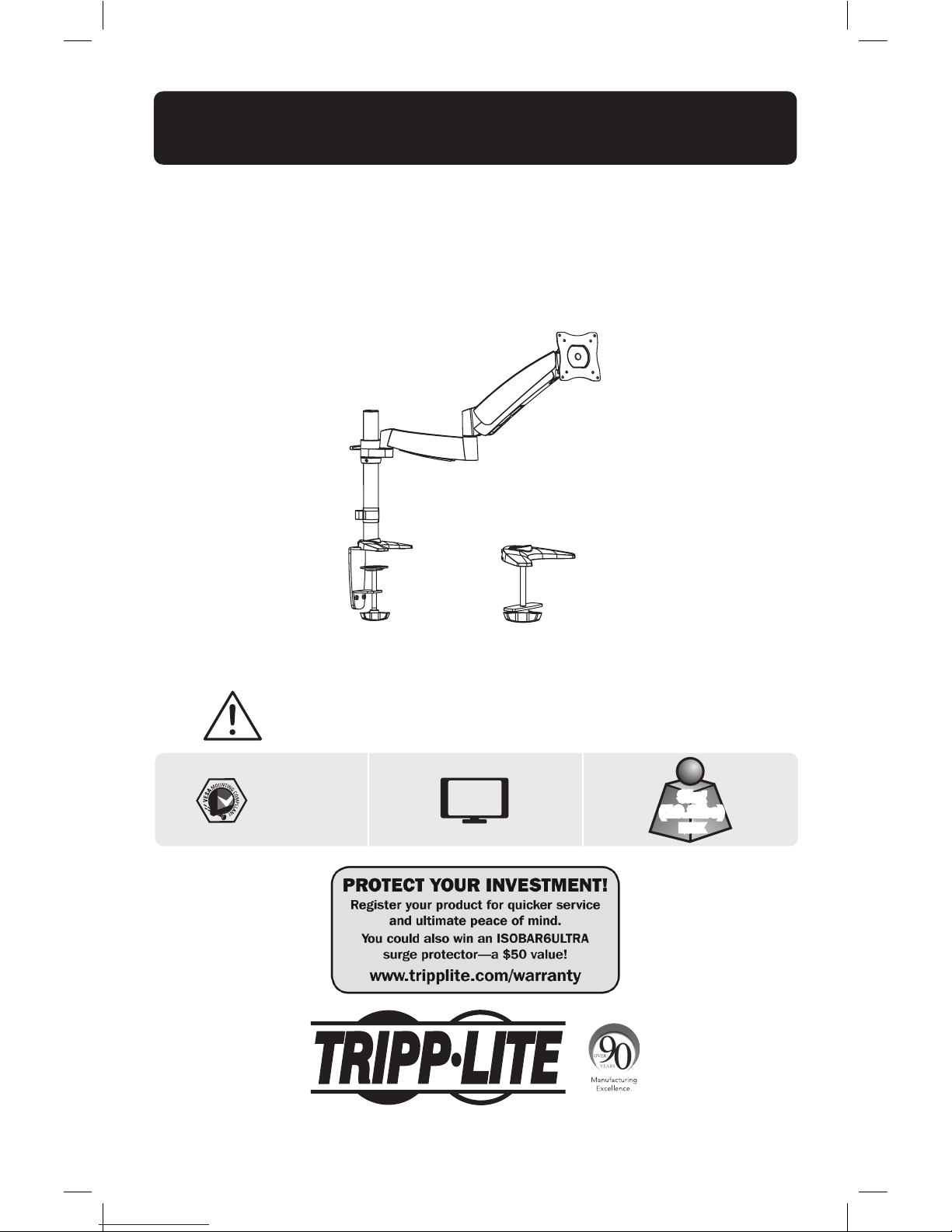
Owner’s Manual
Full Motion
Flat Screen Desk Mount
MODEL: DDR1327S
CAUTION: DO NOT EXCEED MAXIMUM LISTED WEIGHT CAPACITY. SERIOUS INJURY OR
PROPERTY DAMAGE MAY OCCUR!
1111 W. 35th Street, Chicago, IL 60609 USA • www.tripplite.com/support
Copyright © 2014 Tripp Lite. All rights reserved.
75x75
100x100
27”
MAX
9kg
(19.8lbs)
MAX
Español 11 • Français 21 • Русский 31 • Deutsch 41
14-04-247-933321.indb 1 5/6/2014 1:46:08 PM
Page 2

2
NOTE: Read the entire instruction manual before you start installation and assembly.
Warranty & Warranty Registration
WARNING
• Do not begin the installation until you have read and understood the instructions
and warnings contained in this manual. If you have any questions regarding any
of the instructions or warnings, please visit www.tripplite.com/support.
• This mounting bracket was designed to be installed and utilized ONLY as
specified in this manual. Improper installation of this product may cause damage
or serious injury.
• Make sure that the mounting surface can safely support the combined load of
the equipment and all attached hardware and components.
• Always use an assistant or mechanical lifting equipment to safely lift and position
equipment.
• Tighten screws rmly, but do not over-tighten. Over-tightening can damage the
items, greatly reducing their holding power.
• This product is intended for indoor use only. Using this product outdoors could
lead to product failure and personal injury.
5-Year Limited Warrant
Seller warrants this product, if used in accordance with all applicable instructions, to be free from original defects
in material and workmanship for a period of 5 years from the date of initial purchase. If the product should
prove defective in material or workmanship within that period, Seller will repair or replace the product, in its sole
discretion.
THIS WARRANTY DOES NOT APPLY TO NORMAL WEAR OR TO DAMAGE RESULTING FROM ACCIDENT, MISUSE,
ABUSE OR NEGLECT. SELLER MAKES NO EXPRESS WARRANTIES OTHER THAN THE WARRANTY EXPRESSLY
SET FORTH HEREIN. EXCEPT TO THE EXTENT PROHIBITED BY APPLICABLE LAW, ALL IMPLIED WARRANTIES,
INCLUDING ALL WARRANTIES OF MERCHANTABILITY OR FITNESS, ARE LIMITED IN DURATION TO THE WARRANTY
PERIOD SET FORTH ABOVE; AND THIS WARRANTY EXPRESSLY EXCLUDES ALL INCIDENTAL AND CONSEQUENTIAL
DAMAGES. (Some states do not allow limitations on how long an implied warranty lasts, and some states do not
allow the exclusion or limitation of incidental or consequential damages, so the above limitations or exclusions
may not apply to you. This warranty gives you specific legal rights, and you may have other rights which vary from
jurisdiction to jurisdiction).
WARNING: The individual user should take care to determine prior to use whether this device is suitable, adequate
or safe for the use intended. Since individual applications are subject to great variation, the manufacturer makes
no representation or warranty as to the suitability or fitness of these devices for any specific application.
WARRANTY REGISTRATION
Visit www.tripplite.com/warranty today to register the warranty for your new Tripp Lite product. You’ll be
automatically entered into a drawing for a chance to win a FREE Tripp Lite product!*
* No purchase necessary. Void where prohibited. Some restrictions apply. See website for details.
Tripp Lite has a policy of continuous improvement. Specifications are subject to change without notice.
14-04-247-933321.indb 2 5/6/2014 1:46:08 PM
Page 3
3
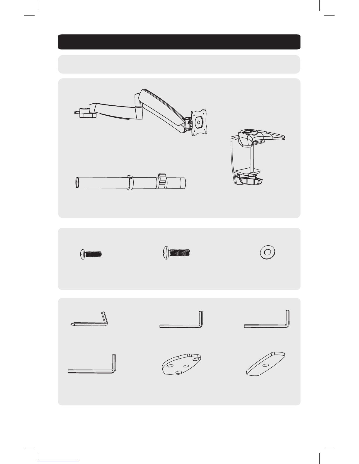
Component Checklist
IMPORTANT: Ensure that you have received all parts according to the component checklist prior to
installing. If any parts are missing or faulty, visit www.tripplite.com/support for service.
Pole (x1)
Desk Clamp Assembly (x1)
M4X14 (x4) M5X14 (x4) D5 Washer (x4)
Package M
Package P
Adapter Bracket Assembly (x1)
3mm Hex Key (x1)
6mm Hex Key (x1)
4mm Hex Key (x1)
Base Plate (x1)
5mm Hex Key (x1)
Pad (x1)
14-04-247-933321.indb 3 5/6/2014 1:46:08 PM
Page 4

4
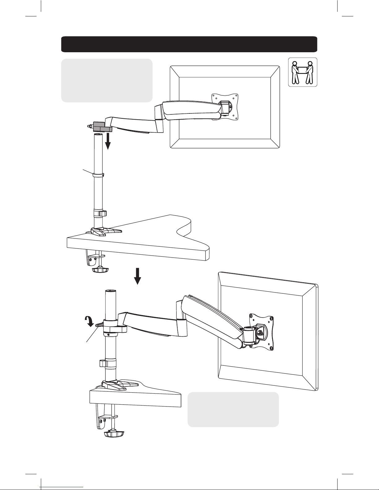
1. Install the Pole and Desk Clamp Assembly
2. Desk Installation
• Determine approximate location for mount, keeping in mind display size, height adjustment and pitch/roll
requirements.
• Slip the desk mount assembly over the edge of desk so that clamp fully contacts desk edge.
• Turn the knob to adjust the clamp to edge of desk and secure it tightly.
Note: min. desktop thickness=10mm (.4”)
max. desktop thickness=90mm (3.5”)
2a. Edge Installation
tighten
loosen
collar
tighten
tighten
3mm Hex Key
3mm Hex Key
3mm Hex Key
adjustable height
14-04-247-933321.indb 4 5/6/2014 1:46:08 PM
Page 5

5
2. Desk Installation
Disassemble the desk clamp assembly by removing the clamp
adjustment screw and the three attachment screws from the
base plate.
Re-install the base plate with three retained attachment screws. Tighten securely.
From below the desk, insert retained clamp adjustment screw through Pad and up through the hole in the desk.
Thread screw by turning the knob into base plate but do not tighten completely at this time. Center the desk
mount assembly over the hole and then securely tighten screw.
Note: min. hole diameter =10mm (.4”)
max. hole diameter =70mm (2.75”)
2b. Hole Installation
Pad
Clamp Adjustment Screw
Base Plate
Rubber Pad
Attachment Screw
4mm Hex Key
14-04-247-933321.indb 5 5/6/2014 1:46:09 PM
Page 6

6
3. Install Adapter Bracket
Lift the display and align the rear mounting
holes with the mount’s VESA plate.
Attach the display to the VESA plate with the appropriate included screws.
Do not over-tighten screws
D5 Washer
M4X14
M5X14
TV
TV
TV
14-04-247-933321.indb 6 5/6/2014 1:46:09 PM
Page 7
7
4. Install Adapter Bracket Assembly (attached display)
Using an assistant or mechanical
lifting equipment, lift the display with
attached VESA plate. Then slide the
adapter bracket assembly (with the
display attached) down the pole until it
touches the collar.
Pulling up on the handle allows the
arm to rotate 360 degrees in either
direction. Releasing the handle enables
tightening or adjustment.
tighten
Collar
Adjustable Handle
14-04-247-933321.indb 7 5/6/2014 1:46:09 PM
Page 8

8
5. Height Adjustment
Tighten the socket
screw if the arm
assembly’s joints make
popping sounds during
adjustment.
Keep the wall mount arm level during tension adjustment. You may need to slightly loosen or tighten the
adjustment screw using the provided Hex Keys depending on the weight of display installed.
If display settles on its own, rotate adjustment screw towards the “+” symbol.
If display rises on its own, rotate adjustment screw towards the “-” symbol.
6mm Hex Key
14-04-247-933321.indb 8 5/6/2014 1:46:09 PM
Page 9
9
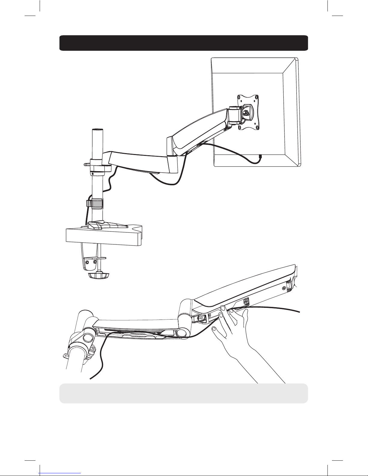
6. Cable Management
FOLD 3
DUSTCATCHER
Connect the cables to the display. Press cable cover inward to route the cables through the space.
Note: Leave slack in cable for arm movement.
14-04-247-933321.indb 9 5/6/2014 1:46:09 PM
Page 10

10
360°
7. Adjustment
To correct the tilting angle, tighten the
adjustment screws using the provided
Hex Keys (or tighten the knob).
Adjust to the desired location or tilt.
+90°
-40°
Max 335mm (13”)
Height Adjustment
Maintenance
• Check that the bracket is secure and safe to use at regular intervals (at least every three months).
• Please visit www.tripplite.com/support if you have any questions.
360°
5mm
Hex Key
1111 W. 35th Street, Chicago, IL 60609 USA • www.tripplite.com/support
14-04-247-933321.indb 10 5/6/2014 1:46:12 PM
Page 11

11
Manual del Propietario
Instalación en Escritorio de
Soporte para Pantalla Plana
con Movimiento Completo
MODELO: DDR1327S
PRECAUCIÓN: NO EXCEDA LA CAPACIDAD MÁXIMA DE CARGA INDICADA.
¡PUEDE OCURRIR UNA LESIÓN SEVERA O DAÑO A LA PROPIEDAD!
1111 W. 35th Street, Chicago, IL 60609 USA • www.tripplite.com/support
Copyright © 2014 Tripp Lite. Todos los derechos reservados.
75 x 75
100 x 100
9 kg
(19.8 lbs)
MÁX
English 1 • Français 21 • Русский 31 • Deutsch 41
MÁS DE
13 - 27
pulg.
14-04-247-933321.indb 11 5/6/2014 1:46:13 PM
Page 12

12
NOTA: Lea completo el manual de instrucciones antes de iniciar la instalación y ensamble.
Garantía
ADVERTENCIA
• No inicie la instalación hasta que haya leído y entendido las instrucciones
y advertencias contenidas en este manual. Si tiene algunas preguntas con
respecto a alguna de las instrucciones o advertencias, visite por favor
www.tripplite.com/support.
• El soporte de instalación fue diseñado para instalarse y usarse SOLAMENTE
como se especifica en este manual. La instalación incorrecta de este producto
puede causar daños o lesiones severas.
• Este producto debe ser instalado únicamente por alguien con una buena
habilidad mecánica, experiencia básica de construcción y un entendimiento
completo de este manual de instrucciones.
• Cerciórese que la supercie de instalación pueda soportar con seguridad la
carga combinada de todo el hardware y componentes instalados.
• Si se instala en paredes con entramados de madera, cerciórese que los
tornillos de instalación estén anclados en el centro de los montantes. Es muy
recomendable el uso de un detector de montantes.
• Utilice siempre un ayudante o equipo de elevación mecánico para levantar y
colocar el equipo con seguridad.
• Apriete los tornillos rmemente pero no en exceso. Apretar excesivamente los
tornillos puede dañar los componentes, reduciendo grandemente su capacidad
de soporte.
• Este producto está diseñado para usarse sólo en interiores. El utilizar este
producto en exteriores podría conducir a fallas del producto y lesiones
personales.
Garantía Limitada por 5 Años
El vendedor garantiza este producto, si se usa de acuerdo con todas las instrucciones aplicables, de que está
libre de defectos en material y mano de obra por un período de 5 años a partir de la fecha de compra inicial. Si
el producto prueba ser defectuoso en material o mano de obra dentro de ese período, el vendedor reparará o
reemplazará el producto a su entera discreción.
ESTA GARANTÍA NO APLICA AL DESGASTE NORMAL O A DAÑOS RESULTANTES DE ACCIDENTES, MAL USO,
ABUSO O NEGLIGENCIA. EL VENDEDOR NO OTORGA GARANTÍAS EXPRESAS DISTINTAS DE LA ESTIPULADA AQUÍ.
EXCEPTO A LA EXTENSIÓN PROHIBIDA POR LA LEY APLICABLE, TODAS LAS GARANTÍAS IMPLÍCITAS, INCLUYENDO
TODAS LAS GARANTÍAS DE COMERCIALIZACIÓN O IDONEIDAD, ESTÁN LIMITADAS EN DURACIÓN AL PERÍODO
DE GARANTÍA ESTABLECIDO; Y ESTA GARANTÍA EXCLUYE EXPRESAMENTE TODOS LOS DAÑOS INCIDENTALES Y
CONSECUENCIALES. (Algunos estados no permiten limitaciones en cuanto dura una garantía y algunos estados
no permiten la exclusión de limitación de daños incidentales o consecuenciales, de modo que las limitaciones
anteriores pueden no aplicar para usted. Esta garantía le otorga derechos legales especícos y usted puede tener
otros derechos que pueden variar de una jurisdicción a otra).
ADVERTENCIA: Antes de usarlo, cada usuario debe debe tener cuidado al determinar si este dispositivo es
adecuado o seguro para el uso previsto. Ya que las aplicaciones individuales están sujetas a gran variación, el
fabricante no garantiza la adecuación de estos dispositivos para alguna aplicación especíca.
Tripp Lite tiene una política de mejora continua. Las especicaciones están sujetas a cambio sin previo aviso.
14-04-247-933321.indb 12 5/6/2014 1:46:13 PM
Page 13

13
Lista de Comprobación de Componentes
IMPORTANTE:
Asegúrese antes de instalar, de haber recibido todas las partes de acuerdo a la lista de
comprobación de componentes. Si faltase cualquier parte o estuviese dañada,
visite www.tripplite.com/support para solicitar servicio.
Poste (x1)
Abrazadera de Escritorio (x1)
M4X14 (x4) M5X14 (x4) Arandela D5 (x4)
Paquete M
Paquete P
Soporte de Adaptador (x1)
Llave Hexagonal de
3 mm (x1)
Llave Hexagonal de
6 mm (x1)
Llave Hexagonal de
4 mm (x1)
Placa de Base (x1)
Llave Hexagonal de
5 mm (x1)
Almohadilla (x1)
14-04-247-933321.indb 13 5/6/2014 1:46:13 PM
Page 14

14
1. Instale el Poste y la Abrazadera de Escritorio
2. Instalación en el Escritorio
• Determine la ubicación aproximada para instalación, teniendo en cuenta los requerimientos de tamaño de
pantalla, ajuste de altura e inclinación/giro.
• Deslice el conjunto de instalación de escritorio sobre el borde del escritorio de modo que la abrazadera haga
contacto completo con el borde del escritorio.
• Gire la perilla para ajustar la abrazadera al borde del escritorio y asegúrela rmemente.
Nota: Espesor mínimo de escritorio=10 mm (0.4”)
Espesor máximo de escritorio=90 mm (3.5”)
Instalación del 2o. Borde
apretar
aojar
collarín
apretar
apretar
Llave Hexagonal de
3 mm
Llave
Hexagonal
de 3 mm
Llave Hexagonal de 3 mm
altura ajustable
14-04-247-933321.indb 14 5/6/2014 1:46:13 PM
Page 15

15
2. Instalación en el Escritorio
Desarme el conjunto de la abrazadera de escritorio retirando
el tornillo de ajuste de la abrazadera y los tres tornillos de
instalación de la placa de base.
Reinstale la placa de base con tres tornillos de sujeción. Apriete con rmeza.
Desde abajo del escritorio, inserte el tornillo de sujeción de la abrazadera a través de la almohadilla y hacia
arriba a través del oricio en el escritorio. Enrosque el tornillo girando la perilla en la placa de base pero no
apriete completamente en este momento. Centre el conjunto de instalación en escritorio sobre el oricio y
entonces apriete firmemente el tornillo.
Nota: Diámetro mín. de oricio=10 mm (0.4”)
Diámetro máx. de oricio=70 mm (2.75”)
2b. Instalación a Través de un Oricio en el Escritorio
Almohadilla
Tornillo de Ajuste de Abrazadera
Placa de Base
Almohadilla de
Caucho
Tornillo de Acoplamiento
Llave Hexagonal de
4 mm
14-04-247-933321.indb 15 5/6/2014 1:46:13 PM
Page 16

16
3. Instale el Soporte del Adaptador
Levante la pantalla y alinee los orificios
de instalación posteriores con la placa de
instalación VESA.
TV
TV
TV
Acople la pantalla a la placa VESA con los tornillos adecuados incluidos.
Asegure firmemente todos los tornillos. No apriete excesivamente.
Arandela D5
M4X14
M5X14
14-04-247-933321.indb 16 5/6/2014 1:46:14 PM
Page 17

17
4. Instale el Soporte del Adaptador (pantalla instalada)
Usando un ayudante o equipo de
elevación mecánico, levante la pantalla
con la placa VESA acoplada. Deslice el
soporte del adaptador (con la pantalla
instalada) hacia abajo del poste hasta
que toque el collarín.
Jalar hacia arriba la manija permite al
brazo girar 360 grados en cualquier
dirección. El soltar la manija permite
el apriete o ajuste.
apretar
Collarín
Manija Ajustable
14-04-247-933321.indb 17 5/6/2014 1:46:14 PM
Page 18

18
5. Ajuste la Altura
Apriete el tornillo allen si
las uniones del conjunto
truenan durante el
ajuste.
Mantenga nivelado el brazo del soporte de pared durante el ajuste de la tensión. Puede necesitar apretar o
aojar ligeramente el tornillo de ajuste con la llaves hexagonales suministradas, dependiendo del peso de la
pantalla instalada.
Si la pantalla se baja por sí misma, gire el tornillo de ajuste hacia el símbolo “+”.
Si la pantalla se levanta por sí misma, gire el tornillo de ajuste hacia el símbolo “-”.
Llave Hexagonal de
6 mm
14-04-247-933321.indb 18 5/6/2014 1:46:14 PM
Page 19

19
6. Manejo del Cableado
FOLD 3
DUSTCATCHER
Conecte los cables a la pantalla. Oprima la cubierta de los cables hacia adentro para conducir los cables a
través del espacio.
Nota: Deje una holgura en el cable para el movimiento del brazo.
14-04-247-933321.indb 19 5/6/2014 1:46:14 PM
Page 20

20
360°
7. Ajuste
Para corregir el ángulo de inclinación, apriete
el tornillo de ajuste usando la llave hexagonal
suministrada (o apriete la perilla).
Ajuste a la posición o inclinación deseada.
+90°
-40°
Ajuste de Altura Máx. 335 mm
(13”)
Mantenimiento
• Compruebe a intervalos regulares (al menos cada tres meses) que el soporte esté seguro para usarse.
• Si tiene alguna pregunta, visite por favor a www.tripplite.com/support.
360°
Llave
Hexagonal
de 5 mm
1111 W. 35th Street, Chicago, IL 60609 USA • www.tripplite.com/support
MÁS DE
14-04-247-933321.indb 20 5/6/2014 1:46:16 PM
Page 21

21
Manuel de l'utilisateur
Support de bureau de
mouvement complet
pour écran plat
MODÈLE : DDR1327S
MISE EN GARDE : NE PAS EXCÉDER LA CAPACITÉ PONDÉRALE MAXIMUM INDIQUÉE.
DES BLESSURES GRAVES OU DES DOMMAGES MATÉRIELS RISQUENT DE SE PRODUIRE!
1111 W. 35th Street, Chicago, IL USA 60609 • www.tripplite.com/support
Droits d'auteur © 2014 Tripp Lite. Tous droits réservés.
75x75
100x100
9 kg
(19,8 lbs)
MÁX
English 1 • Español 11 • Русский 31 • Deutsch 41
13 - 27 po
(33 - 68,5 cm)
14-04-247-933321.indb 21 5/6/2014 1:46:16 PM
Page 22

22
REMARQUE : Lire le manuel d'instructions en entier avant de commencer l'installation et l'assemblage.
Garantie
AVERTISSEMENT
• Ne pas commencer l’installation avant d’avoir lu et compris les instructions et
les avertissements contenus dans le présent manuel. Si vous avez des questions
concernant les instructions ou les avertissements, veuillez visiter
www.tripplite.com/support.
• Ce support de montage a été conçu pour être installé et utilisé UNIQUEMENT
tel que spécifié dans le présent manuel. Une mauvaise installation de ce produit
pourrait causer des dommages ou des blessures graves.
• Ce produit ne devrait être installé que par une personne ayant de bonnes
aptitudes en mécanique et une expérience de base en construction de même
qu’une pleine connaissance du présent manuel d’instructions.
• S’assurer que la surface d’appui peut supporter sans risque la charge combinée
de l’équipement et de tout le matériel et composants attachés.
• Si le produit est monté sur des montants muraux en bois, s’assurer que les vis
de montage sont ancrées au centre des montants. Il est fortement recommandé
d’utiliser un localisateur de montants.
• Toujours faire appel à un assistant ou utiliser de l’équipement de levage
mécanique pour soulever et positionner l’équipement sans risque.
• Serrer fermement les vis, mais sans trop serrer. Trop serrer les vis risquerait de
les endommager, réduisant considérablement leur résistance à l’arrachement.
• Ce produit est prévu pour être utilisé à l’intérieur uniquement. L’utilisation de ce
produit à l’extérieur pourrait entraîner une défaillance du produit et des lésions
corporelles.
Garantie limitée de 5 ans
Le vendeur garantit que ce produit, s'il est utilisé conformément à toutes les instructions applicables, est exempt
de tous défauts de matériaux et de fabrication pour une période de 5 ans à partir de la date d'achat initiale. Si le
produit s'avère défectueux en raison d'un vice de matière ou de fabrication au cours de cette période, le vendeur
s'engage à réparer ou remplacer le produit, à sa seule discrétion.
CETTE GARANTIE NE S'APPLIQUE PAS À L'USURE NORMALE OU AUX DOMMAGES RÉSULTANT D'UN ACCIDENT,
D'UNE MAUVAISE UTILISATION, D'UN ABUS OU D'UNE NÉGLIGENCE. LE VENDEUR NE DONNE AUCUNE GARANTIE
EXPRESSE AUTRE QUE LA GARANTIE EXPRESSÉMENT DÉCRITE DANS LE PRÉSENT DOCUMENT. SAUF DANS LA
MESURE INTERDITE PAR LA LOI APPLICABLE, TOUTE GARANTIE IMPLICITE, Y COMPRIS TOUTES LES GARANTIES
DE QUALITÉ MARCHANDE OU D'ADAPTATION, SONT LIMITÉES À LA PÉRIODE DE GARANTIE CI-DESSUS ET CETTE
GARANTIE EXCLUT EXPRESSÉMENT TOUS DOMMAGES DIRECTS ET INDIRECTS. (Certains États ne permettent pas
de limitations sur la durée d'une garantie implicite, et certains États ne permettent pas l'exclusion ou la limitation
des dommages fortuits ou consécutifs, de sorte que les limitations ou exclusions susmentionnées peuvent ne pas
s'appliquer à vous. Cette garantie vous donne des droits légaux spéciques, et vous pouvez avoir d'autres droits
qui varient selon la juridiction).
AVERTISSEMENT : L'utilisateur individuel doit prendre soin de déterminer avant l'utilisation si cet appareil est
approprié, adéquat et sûr pour l'usage prévu. Puisque les utilisations individuelles sont sujettes à des variations
importantes, le fabricant ne fait aucune déclaration ou garantie quant à l'aptitude ou l'adaptation de ces dispositifs
pour une application spécifique.
La politique de Tripp Lite en est une d'amélioration continue. Les spécications sont sujettes à changement sans
préavis.
14-04-247-933321.indb 22 5/6/2014 1:46:16 PM
Page 23

23
Liste de vérification des composants
IMPORTANT :
Veuillez vous assurer d'avoir reçu toutes les pièces conformément à la liste de
vérication des composants avant de procéder à l'installation. Si des pièces sont
manquantes ou défectueuses, visitez www.tripplite.com/support pour obtenir de l'aide.
Pôle (x1)
Ensemble de la bride pour bureau (x1)
M4X14 (x4) M5X14 (x4) Rondelle D5 (x4)
Emballage M
Emballage P
Ensemble du support d'adaptateur (x1)
Clé hexagonale de
3 mm (x1)
Clé hexagonale de
6 mm (x1)
Clé hexagonale de
4 mm (x1)
Socle (x1)
Clé hexagonale de
5 mm (x1)
Coussinet (x1)
14-04-247-933321.indb 23 5/6/2014 1:46:16 PM
Page 24

24
1. Installer le pôle et l'ensemble de la bride pour bureau.
2. Installation sur un bureau
• Déterminer l'emplacement approximatif du support en gardant à l'esprit les exigences quant à la taille de
l'écran, au réglage de la hauteur et l'angle/pivotement.
• Faire glisser l'ensemble du support pour bureau sur le rebord du bureau de façon à ce que la bride entre
entièrement en contact avec le rebord du bureau.
• Tourner le bouton pour ajuster la bride au rebord du bureau et la maintenir solidement en place.
Remarque :
épaisseur min. du dessus du bureau=10 mm (0,4 po)
épaisseur max. du dessus du bureau=90 mm (3,5 po)
2a. Installation sur le rebord
serrer
desserrer
collier
serrer
serrer
Clé hexagonale de
3 mm
Clé
hexagonale
de 3 mm
Clé hexagonale
de 3 mm
hauteur réglable
14-04-247-933321.indb 24 5/6/2014 1:46:17 PM
Page 25

25
2. Installation sur un bureau
Démonter l’ensemble de la bride pour bureau en enlevant la
vis de réglage de la bride et les trois vis de fixation du socle.
réinstaller le socle avec trois vis de fixation retenues. Bien serrer en place.
En travaillant sous le bureau, insérer la vis de réglage de la bride de retenue à travers le coussinet et à travers
le trou dans le bureau. Visser la vis en tournant le bouton dans le socle, mais ne pas serrer complètement à ce
stade. Centrer l'ensemble du support de bureau au-dessus du trou, puis bien serrer la vis.
Remarque :
diamètre min. du trou =10 mm (0,4 po)
diamètre max. du trou =70 mm (2,75 po)
2b. Installation avec un trou
Coussinet
Vis de réglage de la bride
Socle
Coussinet de
caoutchouc
Vis de fixation
Clé hexagonale de 4 mm
14-04-247-933321.indb 25 5/6/2014 1:46:17 PM
Page 26

26
3. Installer le support d'adaptateur.
Soulever l’écran et aligner les trous de
montage arrière avec avec la plaque VESA du
montage.
TV
TV
TV
Attacher l’écran à la plaque VESA en utilisant les vis appropriées incluses.
Serrer fermement toutes les vis. Ne pas trop serrer.
Rondelle D5
M4X14
M5X14
14-04-247-933321.indb 26 5/6/2014 1:46:17 PM
Page 27

27
4. Installer l'ensemble du support d'adaptateur (écran attaché).
Faire appel à un assistant ou utiliser
de l’équipement de levage mécanique
pour soulever l’écran avec la plaque
VESA déjà en place. Faire glisser
l’ensemble du support d’adaptateur
(avec l’écran attaché) vers le bas le
long du pôle jusqu’à ce qu’il touche
le collier.
Le fait de tirer sur la poignée permet
au bras de tourner sur 360 degrés
dans l'un ou l'autre sens. Le fait de
relâcher la poignée permet de serrer
ou d'effectuer des ajustements.
serrer
Collier
Poignée réglable
14-04-247-933321.indb 27 5/6/2014 1:46:17 PM
Page 28

28
5. Réglage de la hauteur
Serrer la vis creuse si
les joints de l’ensemble
du bras font un bruit
de claquage durant le
réglage.
Garder le bras de montage mural au niveau durant le réglage de la tension. Il peut s’avérer nécessaire de
desserrer ou de serrer légèrement la vis de réglage en utilisant la clé hexagonale fournie en fonction du poids de
l’écran installé.
Si l'écran s'abaisse de lui-même, tourner la vis de réglage vers le symbole « + ».
Si l'écran s'élève de lui-même, tourner la vis de réglage vers le symbole « - ».
Clé hexagonale de
6 mm
14-04-247-933321.indb 28 5/6/2014 1:46:17 PM
Page 29

29
6. Gestion des câbles
FOLD 3
DUSTCATCHER
Brancher les câbles à l'écran. Pousser le couvre-câble vers l'intérieur pour acheminer les câbles à travers
l'espace.
Remarque : Laisser sufsamment de mou dans le câble pour permettre le mouvement du bras.
14-04-247-933321.indb 29 5/6/2014 1:46:17 PM
Page 30

30
360°
7. Réglage
Pour corriger l’angle d’inclinaison, serrer
la vis de réglage au moyen des clés
hexagonales fournies (ou serrer le bouton).
Régler à l'endroit et selon l'angle désirés.
+90°
-40°
Max 335 mm (13 po)
Réglage de la hauteur
Entretien
• Vérier à intervalles réguliers que le support peut être utilisé de façon sûre et sécuritaire (au moins tous les
trois mois).
• Veuillez visiter www.tripplite.com/support si vous avez des questions.
360°
Clé
hexagonale
de 5 mm
1111 W. 35th Street, Chicago, IL USA 60609 • www.tripplite.com/support
14-04-247-933321.indb 30 5/6/2014 1:46:18 PM
Page 31

31
Руководство пользователя
Настольный плоский экран
с полномасштабным
видеоизображением
МОДЕЛЬ: DDR1327S
ВНИМАНИЕ! НЕ ПРЕВЫШАЙТЕ МАКСИМАЛЬНО ДОПУСТИМЫЙ ВЕС.
ЭТО МОЖЕТ ПРИЧИНИТЬ СУЩЕСТВЕННЫЙ ВРЕД ЗДОРОВЬЮ ЛЮДЕЙ ИЛИ МАТЕРИАЛЬНЫЙ УЩЕРБ!
1111 W. 35th Street, Chicago, IL 60609 USA • www.tripplite.com/support
Охраняется авторским правом © 2014 Tripp Lite. Перепечатка запрещается.
75x75
100x100
9 кг
МАКС.
English 1 • Español 11 • Français 21 • Deutsch 41
13 - 27
дюймов
(33 - 68,5 cm)
14-04-247-933321.indb 31 5/6/2014 1:46:19 PM
Page 32

32
ПРИМЕЧАНИЕ. Перед началом установки и сборки модуля внимательно изучите все разделы руководства.
Гарантийные обязательства
ВНИМАНИЕ
• Не начинайте установку до тех пор, пока не ознакомитесь со всеми указаниями и предупреждениями,
изложенными в настоящем руководстве, и не поймете их смысл. В случае возникновения у вас каких-либо
вопросов относительно любых указаний или предупреждений приглашаем вас посетить страницу
www.tripplite.com/support.
• Этот монтажный кронштейн предназначен для установки и использования ТОЛЬКО в соответствии с
указаниями, изложенными в настоящем руководстве. Неправильная установка данного модуля может
привести к причинению материального ущерба или существенного вреда здоровью людей.
• Установка данного изделия должна производиться только специалистом с достаточной технической
квалификацией и базовыми навыками строительства, в полной мере понимающим смысл информации,
изложенной в настоящем руководстве.
• Убедитесь в том, что монтажная поверхность может с запасом выдерживать суммарную нагрузку,
создаваемую оборудованием и всеми входящими в комплект деталями оснастки и другими компонентами.
• В случае монтажа с креплением к деревянным элементам стенового каркаса следует обеспечить
ввертывание крепежных винтов по центру таких элементов. В этом случае рекомендуется использование
детектора неоднородностей.
• Для безопасного подъема и надлежащего размещения оборудования обязательно обращайтесь за
помощью или пользуйтесь механическими грузоподъемными средствами.
• Винты следует затягивать плотно, но не перетягивая их. Перетягивание может привести к повреждению
крепежных деталей, что значительно ухудшит прочность крепления.
• Данное изделие предназначено для использования только в закрытых помещениях. Использование
данного изделия на открытом воздухе может привести к его выходу из строя и причинению вреда
здоровью людей.
Условия 5-летней ограниченной гарантии
Продавец гарантирует отсутствие изначальных дефектов материала или изготовления в течение 5 лет с момента первой покупки данного изделия
при условии его использования в соответствии со всеми применимыми к нему указаниями. В случае проявления каких-либо дефектов материала
или изготовления в течение указанного периода Продавец осуществляет ремонт или замену данного изделия исключительно по своему усмотрению.
ДЕЙСТВИЕ НАСТОЯЩЕЙ ГАРАНТИИ НЕ РАСПРОСТРАНЯЕТСЯ НА СЛУЧАИ ЕСТЕС ТВЕННОГО ИЗНОСА ИЛИ ПОВРЕЖДЕНИЯ В РЕЗУЛЬТАТЕ АВАРИИ,
НЕНАДЛЕЖАЩЕГО ИСПОЛЬЗОВАНИЯ, НАРУШЕНИЯ ПРАВИЛ ЭКСПЛУАТАЦИИ ИЛИ ХАЛАТНОСТИ. ПРОДАВЕЦ НЕ ПРЕДОСТАВЛЯЕТ НИКАКИХ ЯВНО
ВЫРАЖЕННЫХ ГАРАНТИЙ ЗА ИСКЛЮЧЕНИЕМ ПРЯМО ИЗЛОЖЕННОЙ В НАСТОЯЩЕМ ДОКУМЕНТЕ. ЗА ИСКЛЮЧЕНИЕМ СЛУЧАЕВ, ЗАПРЕЩЕННЫХ
ДЕЙСТВУЮЩИМ ЗАКОНОДАТЕЛЬСТВОМ, ВСЕ ПОДРАЗУМЕВАЕМЫЕ ГАРАНТИИ, ВКЛЮЧАЯ ВСЕ ГАРАНТИИ ПРИГОДНОСТИ ДЛЯ ПРОДАЖИ ИЛИ
ИСПОЛЬЗОВАНИЯ ПО НАЗНАЧЕНИЮ, ОГРАНИЧЕНЫ ПО ПРОДОЛЖИТЕЛЬНОСТИ ДЕЙСТВИЯ ВЫШЕУКАЗАННЫМ ГАРАНТИЙНЫМ СРОКОМ; КРОМЕ ТОГО, ИЗ
НАСТОЯЩЕЙ ГАРАНТИИ ЯВНЫМ ОБРАЗОМ ИСК ЛЮЧАЮТСЯ ВСЕ ПОБОЧНЫЕ, СЛУЧАЙНЫЕ И КОСВЕННЫЕ УБЫТКИ. (В некоторых штатах не допускается
введение ограничений на продолжительность действия тех или иных подразумеваемых гарантий, а в некоторых - исключение или ограничение
размера побочных или косвенных убытков. В этих случаях вышеизложенные ограничения или исключения могут на вас не распространяться.
Настоящая гарантия предоставляет вам конкретные юридические права, а набор других ваших прав может быть различным в зависимости от
юрисдикции).
ВНИМАНИЕ! До начала использования данного устройства пользователь должен убедиться в том, что оно является пригодным, соответствующим
или безопасным для предполагаемого применения. В связи с большим разнообразием конкретных применений производитель не дает каких-либо
заверений или гарантий относительно пригодности данных изделий для какого-либо конкретного применения или их соответствия каким-либо
конкретным требованиям.
Компания Tripp Lite постоянно совершенствует свою продукцию. В связи с этим возможно изменение технических характеристик без
предварительного уведомления.
14-04-247-933321.indb 32 5/6/2014 1:46:19 PM
Page 33

33
Перечень комплектации
ВНИМАНИЕ! Перед началом установки убедитесь в том, что вами получены все детали согласно перечню комплектации. В случае
отсутствия или повреждения каких-либо деталей обратитесь за помощью на страницу www.tripplite.com/support.
Опора (1 шт.)
Зажим для крепления к столу в сборе (1 шт.)
M4X14 (4 шт.) M5X14 (4 шт.) Шайба D5 (4 шт.)
Упаковочный комплект M
Упаковочный комплект P
Переходный кронштейн в сборе (1 шт.)
Шестигранный ключ 3 мм
(1 шт.)
Шестигранный ключ 6 мм
(1 шт.)
Шестигранный ключ 4 мм
(1 шт.)
Основание (1 шт.)
Шестигранный ключ 5 мм
(1 шт.)
Прокладка (1 шт.)
14-04-247-933321.indb 33 5/6/2014 1:46:19 PM
Page 34

34
1. Установите опору и зажим для крепления к столу в сборе
2. Настольная установка
• Определите примерное место монтажа с учетом размера дисплея, обеспечения возможности регулировки высоты и требований,
связанных с шагом резьбы / вращением регулировочного винта.
• Зацепите монтажный кронштейн за край стола таким образом, чтобы зажим соприкасался с краем стола.
• Поверните регулировочную головку таким образом, чтобы зажим совпал по ширине с краем стола и плотно охватывал его.
Примечание: мин. толщина столешницы = 10 мм
макс. толщина столешницы = 90 мм
2a. Установка с креплением к краю стола
затянуть
ослабить
манжета
затянуть
затянуть
Шестигранный ключ
3 мм
Шестигранный
ключ 3 мм
Шестигранный ключ
3 мм
регулируемая высота
14-04-247-933321.indb 34 5/6/2014 1:46:19 PM
Page 35

35
2. Настольная установка
Разберите зажим для крепления к столу путем вывертывания винта регулировки
зажима и трех крепежных винтов из основания.
Установите основание на место с помощью трех оставшихся крепежных винтов. Плотно затяните винты.
Вставьте оставшийся винт регулировки зажима по направлению из-под стола вверх через прокладку и отверстие в столе. Поворотом головки
вверните винт в основание, пока не затягивая его полностью. Вставьте кронштейн для настольного монтажа в сборе по центру отверстия, а затем
плотно затяните винт.
Примечание: мин. диаметр отверстия = 10 мм
макс. диаметр отверстия = 70 мм
2b. Установка в отверстие
Прокладка
Винт регулировки зажима
Основание
Резиновая подкладка
Крепежный винт
Шестигранный ключ 4 мм
14-04-247-933321.indb 35 5/6/2014 1:46:19 PM
Page 36

36
3. Установка переходного кронштейна
Поднимите дисплей и совместите нижние монтажные
отверстия с пластиной VESA, являющейся элементом
кронштейна.
TV
TV
TV
Прикрепите дисплей к пластине VESA с использованием соответствующих винтов, поставляемых в комплекте.
Плотно затяните все винты. Не перетягивайте.
Шайба D5
M4X14
M5X14
14-04-247-933321.indb 36 5/6/2014 1:46:19 PM
Page 37

37
4. Установите переходный кронштейн в сборе (с прикрепленным к нему дисплеем)
Обратившись за помощью или воспользовавшись
механическим подъемным оборудованием,
поднимите дисплей с прикрепленной к нему
пластиной VESA. Спустите переходный кронштейн
(с прикрепленным к нему дисплеем) вниз вдоль
опоры до соприкосновения с манжетой.
При вытягивании рукоятки обеспечивается
возможность поворота кронштейна на 360
градусов в любом направлении. При отпускании
рукоятки обеспечивается возможность
затягивания или регулировки.
затянуть
Манжета
Регулировочная
рукоятка
14-04-247-933321.indb 37 5/6/2014 1:46:20 PM
Page 38

38
5. Регулировка высоты
Если шарниры находящегося
в собранном состоянии
кронштейна издают щелчки
в процессе регулировки,
затяните установочный винт с
внутренним шестигранником.
В процессе регулировки затяжки сохраняйте уровень расположения кронштейна. При помощи торцевого ключа соответствующего размера слегка
ослабьте или затяните регулировочный винт в зависимости от веса дисплея.
В случае самопроизвольного опускания дисплея поверните регулировочный винт в направлении значка “+”.
В случае самопроизвольного подъема дисплея поверните регулировочный винт в направлении значка “–”.
Шестигранный ключ 6 мм
14-04-247-933321.indb 38 5/6/2014 1:46:20 PM
Page 39

39
6. Оптимизация кабельных соединений
FOLD 3
DUSTCATCHER
Подсоедините кабели к дисплею. Нажмите на крышку кабельного отсека по направлению внутрь для прокладки кабелей через прос транство
отсека.
Примечание. Для обеспечения возможности вращения кронштейна кабель должен иметь некоторое провисание.
14-04-247-933321.indb 39 5/6/2014 1:46:20 PM
Page 40

40
360°
7. Регулировка
Для корректировки угла наклона затяните регулировочные
винты с помощью шестигранных ключей, поставляемых в
комплекте (или затяните регулировочную головку).
Установите желаемое положение по высоте и угол
наклона.
+90°
-40°
Максимальный диапазон регулировки
высоты
335 мм
Техническое обслуживание
• Регулярно (не реже, чем раз в три месяца) проверяйте надежность крепления кронштейна и безопасность его использования.
• В с лучае возникновения каких-либо вопросов приглашаем вас посетить страницу www.tripplite.com/support.
360°
Шестигранный
ключ 5 мм
1111 W. 35th Street, Chicago, IL 60609 USA • www.tripplite.com/support
14-04-247-933321.indb 40 5/6/2014 1:46:21 PM
Page 41

41
Benutzerhandbuch
Vollbewegliche
Flachbildschirm-
Tischbefestigung
MODELL: DDR1327S
ACHTUNG: DAS ANGEGEBENE MAXIMALGEWICHT DARF NICHT ÜBERSCHRITTEN WERDEN.
ES KÖNNEN SCHWERE KÖRPERVERLETZUNGEN ODER ERHEBLICHE SACHSCHÄDEN EINTRETEN!
1111 W. 35th Street, Chicago, IL 60609 USA • www.tripplite.com/support
Copyright © 2014 Tripp Lite. Alle Rechte vorbehalten.
75 x 75
100 x 100
9 kg
MAX
English 1 • Español 11 • Français 21 • Русский 31
13 - 27
Zoll
(33 - 68,5 cm)
14-04-247-933321.indb 41 5/6/2014 1:46:22 PM
Page 42

42
HINWEIS: Lesen Sie das gesamte Handbuch, bevor Sie mit der Installation und Montage beginnen.
Garantie
WARNUNG
• Beginnen Sie mit der Installation erst, nachdem Sie die Anweisungen und
Warnungen in diesem Handbuch gelesen und verstanden haben. Falls Sie Fragen
bezüglich der Anweisungen oder Warnungen haben, besuchen Sie
www.tripplite.com/support.
• Die Halterung sollte nur wie in diesem Handbuch angegeben installiert und
verwendet werden. Die unsachgemäße Installation dieses Produkts kann zu
Sachschäden oder schweren Verletzungen führen.
• Dieses Produkt darf nur von einer Person mit guten Montagefähigkeiten und
Grunderfahrung im Bauwesen montiert werden, die alle Anweisungen in der
vorliegenden Montageanleitung vollständig verstanden hat.
• Stellen Sie sicher, dass die verwendete Montageäche das Gewicht des Geräts
sowie des zugehörigen Materials und sämtlicher zugehöriger Komponenten
sicher tragen kann.
• Stellen Sie bei der Montage an einer Holzwand sicher, dass die
Befestigungsschrauben in der Mitte eines Balkens verankert sind. Wir empfehlen
die Verwendung eines Balkensuchers.
• Verwenden Sie eine mechanische Hebevorrichtung, um das Gerät sicher
anzuheben und zu positionieren.
• Die Schrauben fest anziehen, ohne sie zu überdrehen. Durch zu festes Anziehen
können die Schrauben beschädigt werden, wodurch die Haltekraft stark reduziert wird.
• Dieses Produkt ist nur zur Verwendung in geschlossenen Räumen bestimmt. Die
Verwendung im Freien kann zu Fehlfunktionen und Verletzungen führen.
5-Jahres-Garantie
Der Verkäufer garantiert für einen Zeitraum von fünf Jahren ab Kaufdatum, dass das Produkt weder Material- noch
Herstellungsfehler aufweist, wenn es gemäß aller zutreffenden Anweisungen verwendet wird. Wenn das Produkt
in diesem Zeitraum Material- oder Herstellungsfehler aufweist, kann der Verkäufer diese Fehler nach eigenem
Ermessen beheben oder das Produkt ersetzen.
DIE NORMALE ABNUTZUNG ODER BESCHÄDIGUNGEN AUFGRUND VON UNFÄLLEN, MISSBRAUCH ODER
UNTERLASSUNG WERDEN VON DIESER GARANTIE NICHT GEDECKT. AUSSER DEN NACHSTEHEND
AUSDRÜCKLICH DARGELEGTEN GARANTIEBEDINGUNGEN ÜBERNIMMT DER VERKÄUFER KEINERLEI
GARANTIE. AUSSER WENN VON DEN GÜLTIGEN GESETZEN UNTERSAGT, SIND ALLE IMPLIZIERTEN
GARANTIEN, EINSCHLIESSLICH ALLE GARANTIEN FÜR DIE GEBRAUCHSTAUGLICHKEIT ODER EIGNUNG AUF
DIE OBEN FESTGELEGTE GARANTIEDAUER BESCHRÄNKT. DIESE GARANTIE SCHLIESST AUSDRÜCKLICH ALLE
FOLGESCHÄDEN UND BEILÄUFIG ENTSTANDENEN SCHÄDEN AUS. (Da einige Länder den Ausschluss oder die
Beschränkung von Folgeschäden oder beiläug entstandenen Schäden sowie den Ausschluss von implizierten
Garantien oder die zeitliche Beschränkung einer implizierten Garantie untersagen, sind die oben genannten
Beschränkungen für Sie möglicherweise nicht zutreffend. Diese Garantie gibt Ihnen bestimmte Rechte. Sie haben
jedoch möglicherweise andere Rechte, die abhängig von der Gerichtsbarkeit variieren können.)
WARNUNG: Der Benutzer muss vor der Verwendung überprüfen, ob das Gerät für den beabsichtigten Zweck
geeignet und angemessen ist und ob der Einsatz sicher ist. Da die Anwendungen variieren können, übernimmt der
Hersteller keine Garantie bezüglich der Eignung dieser Geräte für einen bestimmten Verwendungszweck.
Tripp Lite hat den Grundsatz, sich kontinuierlich zu verbessern. Spezikationen können ohne Ankündigung
geändert werden.
14-04-247-933321.indb 42 5/6/2014 1:46:22 PM
Page 43

43
Komponentenliste
WICHTIG:
Überprüfen Sie, ob Sie alle in der Komponentenliste aufgeführten Teile erhalten haben,
bevor Sie mit der Installation beginnen. Wenn Teile beschädigt oder nicht vorhanden sind,
besuchen Sie www.tripplite.com/support.
Stange (x1)
Tischhalterungssatz (x1)
M4X14 (x4) M5X14 (x4) D5 Beilagscheibe (x4)
Paket M
Paket P
Adapterhalterungssatz (x1)
3 mm Inbusschlüssel (x1)
6 mm Inbusschlüssel (x1)
4 mm Inbusschlüssel (x1)
Basisplatte (x1)
5 mm Inbusschlüssel (x1)
Unterlage (x1)
14-04-247-933321.indb 43 5/6/2014 1:46:22 PM
Page 44

44
1. Installieren der Stange und Tischhalterung
2. Tischinstallation
• Legen Sie die Position für die Befestigung unter Berücksichtigung der Bildschirmgröße, Höhe und Neigung/
Rollen fest.
• Schieben Sie die Tischhalterung über die Kante hinaus, bis die Halterung die Tischkante berührt.
• Drehen Sie den Knopf, um die Halterung an der Tischkante auszurichten, und befestigen Sie die Halterung.
Hinweis: Mindestdicke des Tisches = 10 mm
max. Dicke = 90 mm
2a. Kanteninstallation
anziehen
lockern
Aufsetzrahmen
anziehen
anziehen
3 mm Inbusschlüssel
3 mm Inbusschlüssel
3 mm Inbusschlüssel
einstellbare Höhe
14-04-247-933321.indb 44 5/6/2014 1:46:22 PM
Page 45

45
2. Tischinstallation
Die Tischhalterungsbaugruppe durch Entfernen der
Einstellschraube und der drei Befestigungsschrauben von der
Grundplatte demontieren.
Montieren Sie die Basisplatte mit den drei aufbewahrten Verbindungsschrauben. Ziehen Sie die Schrauben fest.
Stecken Sie die aufbewahrte Einstellschraube für die Halterung von unten durch die Unterlage und das Loch im
Tisch. Drehen Sie die Schraube, indem Sie den Knopf an der Basisplatte drehen, aber ziehen Sie die Schraube
nicht vollständig fest. Zentrieren Sie die Tischhalterung über dem Loch und ziehen Sie die Schraube fest.
Hinweis: Min. Lochdurchmesser = 10 mm
Max. Lochdurchmesser = 70 mm
2b. Lochmontage
Unterlage
Einstellschraube für Halterung
Basisplatte
Gummiunterlage
Verbindungsschraube
4 mm Inbusschlüssel
14-04-247-933321.indb 45 5/6/2014 1:46:22 PM
Page 46

46
3. Installieren der Adapterhalterung
Bildschirm anheben und die hinteren
Montageöffnungen zur VESA-Platte der
Wandbefestigung hin ausrichten.
TV
TV
TV
Den Bildschirm mit den passenden mitgelieferten Schrauben an der VESA-Platte befestigen.
Alle Schrauben fest anziehen. Die Schrauben nicht überdrehen.
D5
Beilagscheibe
M4X14
M5X14
14-04-247-933321.indb 46 5/6/2014 1:46:22 PM
Page 47

47
4. Installieren der Adapterhalterung (angebrachter Bildschirm)
Mit Hilfe eines Assistenten oder einer
mechanischen Hebevorrichtung den
Bildschirm mit der daran befestigten
VESA-Platte anheben. Ziehen Sie
die Adapterhalterung (Bildschirm
angebracht) an der Stange nach unten,
bis sie den Aufsetzrahmen berührt.
Wenn Sie den Griff nach oben ziehen,
kann der Arm in jede Richtung um 360
Grad gedreht werden. Lassen Sie den
Griff zum Anziehen oder Ausrichten los.
anziehen
Aufsetzrahmen
Einstellbarer Griff
14-04-247-933321.indb 47 5/6/2014 1:46:22 PM
Page 48

48
5. Höheneinstellung
Die Inbusschraube
fester anziehen,
wenn das Gelenk
der Armbaugruppe
beim Einstellen ein
knackendes Geräusch
verursacht.
Bei allen Nachzieharbeiten die richtige Stellung des Wandbefestigungsarms beibehalten. Je nach Gewicht des
montierten Bildschirms kann ein leichtes Lockern oder Nachziehen der Einstellschrauben mit dem mitgelieferten
Inbusschlüssel erforderlich sein.
Wenn sich der Bildschirm selbst ausgleicht, drehen Sie die Einstellschraube in Richtung des „+“-Symbols.
Wenn sich der Bildschirm anhebt, drehen Sie die Einstellschraube in Richtung des „-“-Symbols.
6 mm Inbusschlüssel
14-04-247-933321.indb 48 5/6/2014 1:46:22 PM
Page 49

49
6. Kabelführung
FOLD 3
DUSTCATCHER
Schließen Sie die Kabel am Bildschirm an. Drücken Sie die Kabelabdeckung nach innen, um die Kabel durch
die Öffnung zu führen.
Hinweis: Geben Sie dem Kabel etwas Bewegungsspielraum.
14-04-247-933321.indb 49 5/6/2014 1:46:22 PM
Page 50

50
360°
7. Ausrichtung
Zur Korrektur des Neigungswinkels die Einstellschrauben
mit dem mitgelieferten Inbusschlüssel fest ziehen (bzw.
den Knopf festdrehen).
Passen Sie die Position oder Neigung an.
+90°
-40°
Max. 335 mm
Höheneinstellung
Wartung
• Überprüfen Sie in regelmäßigen Abständen (mindestens alle drei Monate), ob die Halterung sicher angebracht ist.
• Falls Sie Fragen haben, besuchen Sie www.tripplite.com/support.
360°
5 mm
Inbusschlüssel
1111 W. 35th Street, Chicago, IL 60609 USA • www.tripplite.com/support
14-04-247 93-3321_RevA
14-04-247-933321.indb 50 5/6/2014 1:46:24 PM
 Loading...