

Page 1

Owner’s Manual
Charging Station Cart
36-Outlet Model: CSC36AC
Table of Contents
1. Important Safety Instructions 2
2. Overview 2
3. Feature Identification 3
4. Zone Labeling 5
5. Setup 6
5.1 Power Requirements 6
5.2 Installing the Handle Bracket, 6
Corner Safety Bumpers and
Power Cord Manager
5.3 Adjusting Storage Shelf Dividers 6
5.4 Connecting Devices and 7
Powering the AC Unit
5.5 Door Locks 8
6. Operation 9
7. Optional Display Mount Adapter Kit 10
8. Specifications 10
9. Storage, Service and Cleaning 10
10. Warranty and Product Registration 11
PROTECT YOUR INVESTMENT!
Register your product for quicker service and ultimate peace of mind.
You could also win an ISOBAR6ULTRA surge protector—a $100 value!
www.tripplite.com/warranty
1111 W. 35th Street, Chicago, IL 60609 USA • www.tripplite.com/support
Copyright © 2017 Tripp Lite. All trademarks are the sole property of their respective owners.
1
Page 2

1. Important Safety Instructions
SAVE THESE INSTRUCTIONS
This manual contains instructions and warnings that must be followed during the installation and operation of the product described in this manual.
Failure to comply may invalidate the warranty and cause property damage or personal injury.
AC Unit:
• Do not use a power adapter to connect the charging station to a power source. Use only the charging station’s AC plug to connect directly to
the supply mains.
• To remove the AC unit from the supply mains, the power cord serves as a disconnect device.
• If any of the following situations arise, schedule an appointment to have your equipment inspected by a service technician:
• The equipment has been exposed to moisture
• The equipment has been dropped and damaged
• The equipment shows obvious signs of breakage
• The equipment is not functioning properly or is not functioning according to the instructions described in this Owner’s Manual
• Use of this equipment in life support applications where failure of this equipment can reasonably be expected to cause the failure of the life support
equipment or to significantly affect its safety or effectiveness is not recommended.
Charging Station Cabinet:
• Keep the charging station in a controlled indoor environment away from moisture, temperature extremes, flammable liquids and gasses, conductive
contaminants, dust and direct sunlight.
• Leave adequate space around the charging station for proper ventilation. Do not block, cover or insert objects into the charging station’s external
ventilation openings.
• The charging station is extremely heavy. Use caution when handling the charging station. Do not attempt to unpack the charging station unassisted.
Use a mechanical device such as a forklift or pallet jack to move the charging station in the shipping container.
• Inspect the shipping container and the charging station for shipping damage. Do not use the charging station if it is damaged.
• Use caution when cutting packing materials. The charging station could be scratched, causing damage not covered by the warranty.
• Save all packing materials for later use. Repacking and shipping the charging station cabinet or equipment without the original packing materials
may cause product damage that will void the warranty.
• The charging station includes four pre-installed locking/swivel casters.
• Always use the included handle when moving the charging station (see section 5.2 Installing the Handle Bracket Corner Safety Bumpers and
Power Cord Manager for more information).
• When moving the charging station cabinet, always push it from behind; never pull it toward you.
• A rolling charging station can cause personal injury and property damage if not properly supervised. If rolling the charging station down a ramp is
required, use extreme caution. Do not attempt to use ramps that have a slope grade greater than 12%.
2. Overview
Your charging station is an all-in-one solution for storing and charging up to 36 devices. With four pre-installed locking/swivel casters and an
attachable, reversible handle accessory, your charging station is ideal for mobile applications. The charging station features a built-in charging timer
unit that alternates the charge hourly between two zones that can each contain up to 18 devices. To prevent theft and device tampering, your charging
station enclosure comes equipped with locking steel doors.
2
Page 3
External Receptacles
Powered
(Internally Switched)
RedRed
ZoneZone
BlueBlue
ZoneZone
Main Power
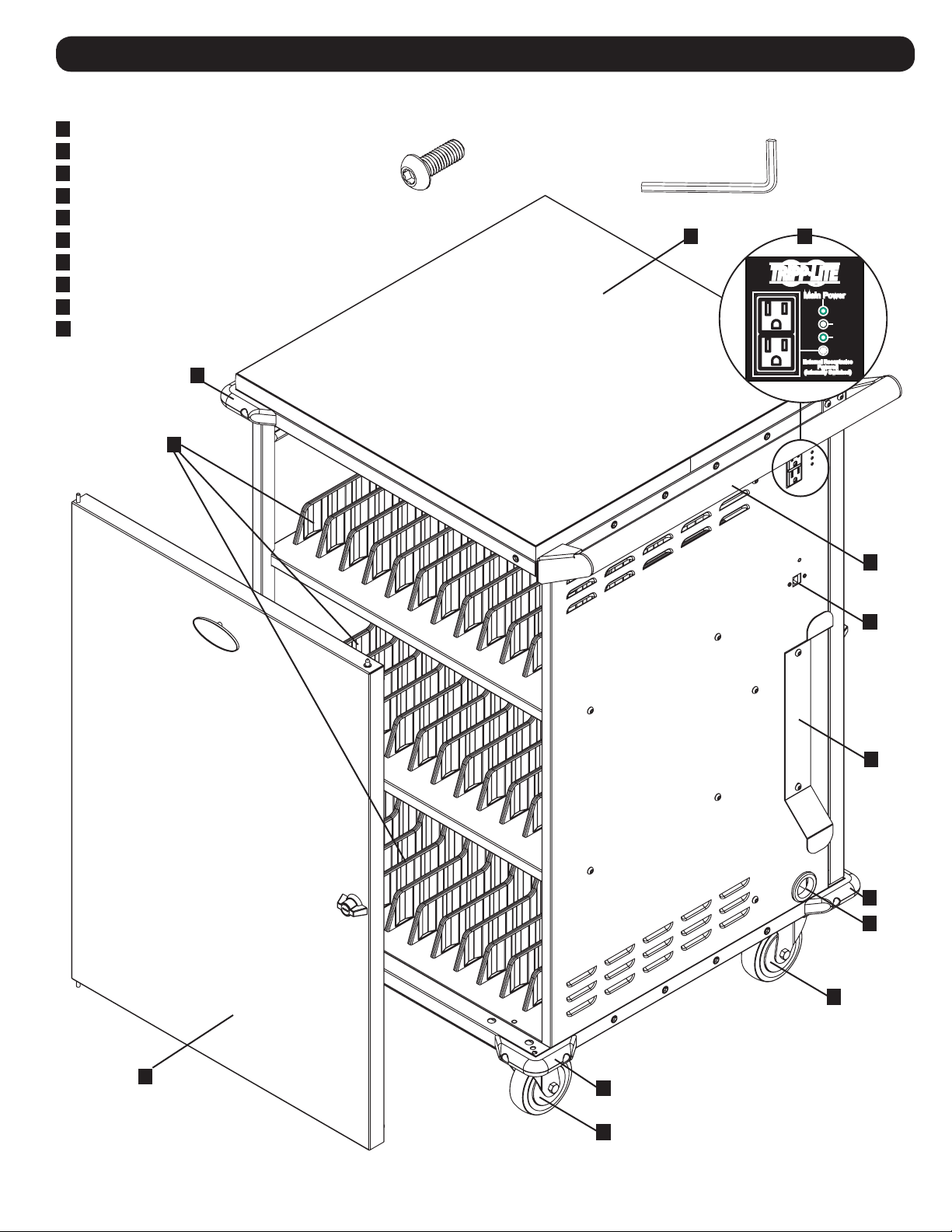
3. Feature Identification
Front View
1
Laminate Desktop Surface
2
Reversible Handle
3
Convenience Outlets and LED Status Indicators
4
Power Cord Manager
5
Power Cord Access Hole
6
Corner Safety Bumpers (6 Total)
7
Storage Shelves with Removable Dividers*
8
Locking Front Door
9
Swivel Locking Casters
10
Cat6 RJ45 Pass Through
6
7
Included Accessory Hardware
10 x Hex Screws Hex Key
31
2
10
4
6
5
9
8
*Each storage shelf is divided into two zones (Red and Blue). The device spaces for each zone are numbered. For more information, refer to 4. Zone Labeling.
3
6
9
Page 4
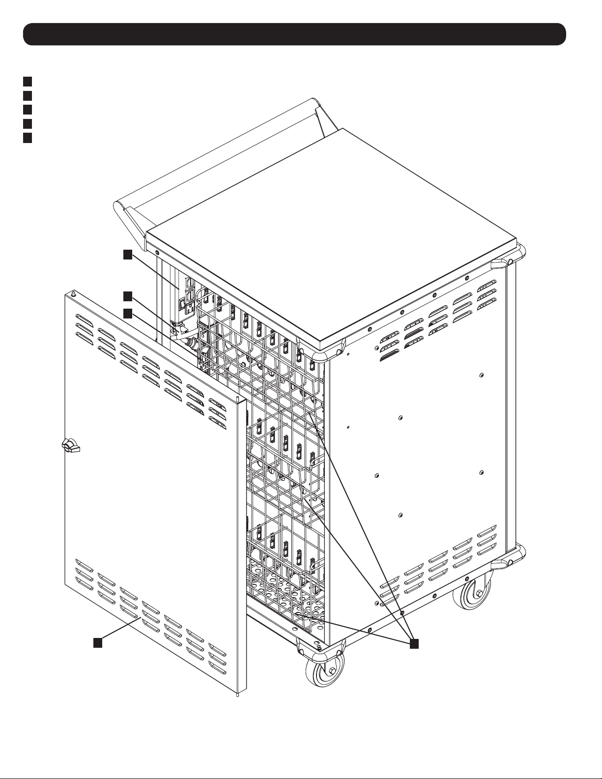
3. Feature Identification
Rear View
11
Charging Timer Unit (Charges 1 Zone/Hour)
12
10 ft. Power Cord with 5-15P Plug
13
Power Brick Storage Baskets (Divided into 2 Zones)
14
18-Outlet AC Power Distribution Units** (2 Total)
15
Locking Rear Door
11
12
14
15
**Each of the charger unit’s outlets are organized in 3 groups of 6 outlets per zone. For more information, refer to 5.4 Connecting Devices and Powering the AC Unit.
4
13
Page 5

4. Zone Labeling
Each storage shelf is divided into two zones (Red and Blue). Each shelf zone can accommodate up to six devices. The device spaces for each zone are
numbered.
Front View
Red Zone
Blue Zone
Numbered Device Slots 1-6
Numbered Device Slots 13-18 Numbered Device Slots 19-24
Numbered Device Slots 25-30 Numbered Device Slots 31-36
Numbered Device Slots 7-12
5
Page 6

5. Setup
Caution! Read All Instructions and Warnings Before Installation!
Warning: Charging stations can be extremely heavy. Do not attempt to unpack the charging station without assistance.
Follow the unpacking instructions document that shipped with this product before proceeding with setup. Use extreme caution
when handling the charging station and be sure to follow all handling and installation instructions. Do not attempt to install
equipment without first stabilizing the charging station.
5.1 Power Requirements
The charging station must be plugged into an AC outlet with a dedicated circuit. An AC outlet with a 20-amp (NEMA 5-20R) AC circuit is recommended
for powering the charging station. The AC outlet used to power the charging station should not be shared. The total wattage of the charging station and
all connected components should not exceed 1440 watts.
5.2 Installing the Handle Bracket, Corner Safety Bumpers and Power Cord Manager
To install the handle bracket, choose a side on which to install the bracket (the same side as the cable access hole grommet and power cord manager
is recommended). Using the included hex key tool and four (4) hex screws, secure the handle bracket to the charging station cabinet A. Then install
the two top corner safety bumpers using four (4) hex screws (two per bumper)
the same side as the cable access hole grommet C.
To install the cord manager, use two (2) hex screws to secure on
B
.
A B
C
5.3 Adjusting Storage Shelf Dividers
Your charging station contains with three non-removable storage shelves with
adjustable dividers. Each shelf can accommodate up to 12 personal electronic devices
(six per zone; see 4. Zone Labeling for more information).
To remove or rearrange the dividers, first open the rear door. Then push in the two tabs
securing the divider to the rear end 1, pull the divider up to disengage from the shelf
tray 2, and pull out to remove 3. Repeat as necessary for additional shelf dividers.
2
3
For illustrative purposes only.
Tray cannot be removed from
unit.
1
6
Page 7

5. Setup
5.4 Connecting Devices and Powering the AC Unit
Your charging station contains three baskets, each with a divider to separate the Red Zone from the Blue Zone. Each half basket corresponds with its
storage shelf zone on the front side of the charging station (refer to 4. Zone Labeling for more information). To connect the device power bricks, place
the bricks in the basket. Working one basket and zone at a time, plug the power brick into its designated outlet on the AC charger unit (see A for
Device/Basket assignments), then run the device cable and connector through a zoned device slot B and into the overhead cable manager C. Repeat
as needed for each zone and basket/shelf.
Notes: Baskets are removable for easier power brick installation. If using fewer than 36 devices, you can adjust the number of shelf dividers for a particular shelf and
zone. For more information, refer to 5.3 Adjusting Storage Shelf Dividers.
Red ZoneBlue Zone
Devices 7-12
Devices 19-24 Devices 13-18
Devices 31-36 Devices 25-30
A
Devices 1-6
B
C
7
Page 8

5. Setup
External Receptacles
Powered
(Internally Switched)
RedRed
ZoneZone
BlueBlue
ZoneZone
Main Power
Connect all devices and place on their respective shelves. Once all devices are connected and stored, find the AC unit’s input plug and cable located
in the charging station’s bottom compartment. Push the input plug through the cable access hole grommet located on the bottom of the charging
station cabinet D. Plug the power cord into the nearest 3-prong, grounded wall outlet.
D
The charging station does not charge all devices simultaneously. The built-in charging timer unit alternates the charge
between zones on an hourly basis. For more information, refer to 6. Operation.
5.5 Door Locks
The doors contain a lock that is accessible with the included keys.
8
Page 9

6. Operation
External Receptacles
Powered
(Internally Switched)
Red
Zone
Blue
Zone
Main Power
The charging station’s built-in charging timer unit alternates the charge hourly between two sets of up to 18 devices (per set). The LED status interface
(shown below) indicates which zone is being charged at any given time by the LED that is illuminated. The two non-charging external convenience
power outlets to the left of the LEDs will not be active while the zones are charging.
To use the two external convenience power outlets, open the rear door. From inside, flip the switch located on the charging timer unit.
Note: The internal outlet located on the charging timer unit is reserved for future expansion.
9
Page 10

7. Optional Display Mount Adapter Kit
Add a television display to your charging station cart with an optional display mount adapter kit (model: CSC36DM). The adapter kit accommodates
displays up to 60 inches and includes all installation hardware. For further installation instructions, refer to the CSC36DM Installation Guide.
8. Specifications
Cabinet Dimensions (H x W x D) 40.03 x 24.30 x 23.56 in. / 1017 x 617 x 598 mm
Unit Weight 110.23 lb. / 50 kg
Load Capacity 250 lb. / 113 kg
AC Receptacles Power Distribution Units: 36 x 5-15R (Divided into Two Zones)
External Convenience Outlets: 2 x 5-15 R (Operated via the Charging Timer Unit Switch)
Internal Outlet: 1 x 5-15R (Reserved for Future Expansion)
Power Requirement Input: 120V AC, 50/60 Hz, 12 Amps
Operating Temperature 32° to 104° F (0° to 40° C)
Operating Humidity 5 to 95% RH, Non-Condensing
9. Storage, Service and Cleaning
Storage
The enclosure should be stored in a controlled indoor environment away from moisture, temperature extremes, flammable liquids and gasses,
conductive contaminants, dust and direct sunlight. Store the enclosure in its original shipping container if possible.
Service
The enclosure is covered by the limited warranty described in this manual. For more information, visit www.tripplite.com/support.
Cleaning
Before cleaning, always power off the charging station by unplugging it from its AC source. Dampen a clean, lint-free cloth with water and wipe down
the unit, as necessary. Allow the surface area to dry before plugging in the unit.
Note: Avoid using abrasive cloths, solvents or aerosol sprays to clean the charging station; doing so can damage the unit.
10
Page 11

10. Warranty and Product Registration
2-Year Limited Warranty
Seller warrants this product, if used in accordance with all applicable instructions, to be free from original defects in material and workmanship for a period of 2 years from the date of
initial purchase. If the product should prove defective in material or workmanship within that period, Seller will repair or replace the product, at its sole discretion.
THIS WARRANTY DOES NOT APPLY TO NORMAL WEAR OR TO DAMAGE RESULTING FROM ACCIDENT, MISUSE, ABUSE OR NEGLECT. SELLER MAKES NO EXPRESS WARRANTIES OTHER
THAN THE WARRANTY EXPRESSLY SET FORTH HEREIN. EXCEPT TO THE EXTENT PROHIBITED BY APPLICABLE LAW, ALL IMPLIED WARRANTIES, INCLUDING ALL WARRANTIES OF
MERCHANTABILITY OR FITNESS, ARE LIMITED IN DURATION TO THE WARRANTY PERIOD SET FORTH ABOVE; AND THIS WARRANTY EXPRESSLY EXCLUDES ALL INCIDENTAL AND
CONSEQUENTIAL DAMAGES. (Some states do not allow limitations on how long an implied warranty lasts, and some states do not allow the exclusion or limitation of incidental or
consequential damages, so the above limitations or exclusions may not apply to you. This warranty gives you specific legal rights, and you may have other rights which vary from
jurisdiction to jurisdiction).
WARNING: The individual user should take care to determine prior to use whether this device is suitable, adequate or safe for the use intended. Since individual applications are
subject to great variation, the manufacturer makes no representation or warranty as to the suitability or fitness of these devices for any specific application.
Product Registration
Visit www.tripplite.com/warranty today to register your new Tripp Lite product. You’ll be automatically entered into a drawing for a chance to win a FREE Tripp Lite product!*
* No purchase necessary. Void where prohibited. Some restrictions apply. See website for details.
Regulatory Compliance Identification Numbers
For the purpose of regulatory compliance certifications and identification, your Tripp Lite product has been assigned a unique series number. The series number can be found on the
product nameplate label, along with all required approval markings and information. When requesting compliance information for this product, always refer to the series number. The
series number should not be confused with the marketing name or model number of the product.
FCC Notice, Class B
This device complies with part 15 of the FCC Rules. Operation is subject to the following two conditions: (1) This device may not cause harmful interference, and (2) this device must
accept any interference received, including interference that may cause undesired operation.
Note: This equipment has been tested and found to comply with the limits for a Class B digital device, pursuant to part 15 of the FCC Rules. These limits are designed to provide
reasonable protection against harmful interference in a residential installation. This equipment generates, uses and can radiate radio frequency energy and, if not installed and used in
accordance with the instructions, may cause harmful interference to radio communications. However, there is no guarantee that interference will not occur in a particular installation. If
this equipment does cause harmful interference to radio or television reception, which can be determined by turning the equipment off and on, the user is encouraged to try to correct
the interference by one or more of the following measures:
• Reorient or relocate the receiving antenna.
• Increase the separation between the equipment and receiver.
• Connect the equipment into an outlet on a circuit different from that to which the receiver is connected.
• Consult the dealer or an experienced radio/TV technician for help.
Any changes or modifications to this equipment not expressly approved by Tripp Lite could void the user’s authority to operate this equipment.
WEEE Compliance Information for Tripp Lite Customers and Recyclers (European Union)
Under the Waste Electrical and Electronic Equipment (WEEE) Directive and implementing regulations, when customers buy new electrical and electronic equipment from
Tripp Lite they are entitled to:
• Send old equipment for recycling on a one-for-one, like-for-like basis (this varies depending on the country)
• Send the new equipment back for recycling when this ultimately becomes waste
Tripp Lite has a policy of continuous improvement. Specifications are subject to change without notice.
11
Page 12

1111 W. 35th Street, Chicago, IL 60609 USA • www.tripplite.com/support
12
17-04-128 93-3692_revB
 Loading...