

Page 1
Owner's Manual
4K/60 HDMI over Fiber
Extender Kit
Model: B127F-1A1-MM-HH
Este manual esta disponible en español en la página de Tripp Lite:
Ce manuel est disponible en français sur le site Web de Tripp Lite :
Русскоязычная версия настоящего руководства представлена на
веб-сайте компании Tripp Lite по адресу: www.tripplite.com/support
www.tripplite.com/support
www.tripplite.com/support
WARRANTY REGISTRATION
Register your product today and be
automatically entered to win an ISOBAR
surge protector in our monthly drawing!
www.tripplite.com/warranty
1111 W. 35th Street, Chicago, IL 60609 USA
Copyright © 2019 Tripp Lite. All rights reserved.
www.tripplite.com/support
1
Page 2

Package Contents
• Transmitter Unit
• Receiver Unit
• Mounting Hardware
• External Power Supply (x2)
Product Features
• HDMI over Duplex LC Fiber Extender Kit extends a 4K (3840x2160) @
60 Hz signal up to 1000 ft. (300 m) from the source
• Supports 4K (3840x2160) @ 60 Hz 4:4:4 maximum video resolution
• Supports 7.1-channel surround sound audio
• HDMI 2.0, HDCP 2.2 and HDR compatible
• Plug and play—no software or drivers required
• Additional HDMI port on the transmitter unit allows connection of a
local display, enabling users to monitor the remote display’s content
• Remote receiver unit features built-in equalization (EQ) control and
auto-EDID image adjustment
• Transmitter and receiver units feature built-in 10G Multimode LC,
850nm, 300M, DDM transceivers
• Local port at transmitter with built-in multi-resolution technology
connects any display without affecting 4K/60 Hz signal transmission
• Includes mounting hardware that allows both the local transmitter
and remote receiver units to be wall-mounted, rack-mounted or polemounted
Optional Accessories
• P569-XXX-CERT or P568-XXX-2A Series High-Speed HDMI 2.0 Cable
• N820-Series 10 Gb Duplex Multimode LC-to-LC Fiber Patch Cable
2
Page 3
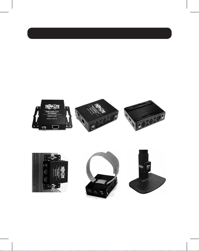
Mounting Instructions
The B127-1A1-MM-HH includes mounting hardware that allows for a
variety of mounting methods. The following images illustrate how the
included mounting brackets can be attached for different installations.
Note: The model shown in the below images is for illustrative purposes only. Your
product may vary by model number, size or port orientation. The mounting options
for all over IP units are the same.
Wall-mount
19” Rack-mount Pole-mount
3
Page 4

Standard Extender Kit Installation
Before installation, check the following settings of your
source(s) and TV/monitor(s):
1. Set the display to 30 Hz. Double-check the factory settings, as the
default can be set to a lower frequency (Hz) than advertised.
2. Ensure the input setting of your monitor is set at HDMI 2.0. Some
displays may have the default setting at HDMI 1.4.
3. Verify your monitor has the HDR feature enabled. Some displays may
have this feature disabled as a factory setting.
4. Check if the Ultra HD (UHD) Deep Color setting is enabled on your
TV/monitor. Confirm with your TV/monitor manufacturer which HDMI
ports support UHD Deep Color.
Note: If you are connecting a local monitor to your installation, the UHD Deep
Color setting may need to be disabled on your local TV/monitor (depending on the
make and model) to achieve 4K 60 Hz resolution.
Notes:
1) Test to ensure the entire installation works properly before pulling cables through
ceilings/walls.
2) To achieve maximum distance and performance, use 10 Gb duplex multimode
fiber cabling, such as Tripp Lite’s N820-Series 10 Gb Duplex Multimode LC-toLC Fiber Cable. Preinstalled 10 Gb transceivers are intended to work with 10 Gb
fiber cables. Using lower-rated fiber cables can result in signal loss or no image.
4
Page 5

Standard Extender Kit Installation
Up to 1000 ft. multimode fiber cable
B127F-1A1-MM-HH
Extender Kit
1
Up to 15 ft. HDMI 2.0 cable at 4K/60 Hz
2
PC with USB
(Keyboard + Mouse)
Control
IR
Source
Sensor
Remote
LOCAL
TRANSMITTER
DVD/BD
Player
1
Make sure all equipment in the installation is powered OFF.
2
Using an HDMI 2.0 cable (such as Tripp Lite P569-XXX-CERT or
LOCAL
USB
Keyboard
REMOTE
RECEIVER
USB
Mouse
RS-232
Scanner/optional
IR
Sensor
Remote
Source
P568-XXX-2A Series cables), connect the HDMI source to the INPUT
port on the local transmitter unit.
3
(Optional) Using an HDMI 2.0 cable (such as Tripp Lite P569-XXX-CERT
or P568-XXX-2A Series cables), connect a local monitor to the
LOCAL port on the local transmitter unit. The LOCAL (orange) LED will
illuminate to indicate the port is connected to a display.
4
Using duplex LC multimode (850 nm) fiber cable (such as Tripp Lite
N820-Series cable), connect the LC fiber port on the local transmitter
unit to the LC fiber port on the remote receiver unit.
5
Page 6

Standard Extender Kit Installation
5
Using an HDMI 2.0 cable (such as Tripp Lite P569-XXX-CERT or
P568-XXX-2A Series cables), connect the remote receiver unit’s HDMI
port to a monitor.
6
Turn on the power to all of your connected displays (local and remote).
7
Connect the external power supply to the local transmitter unit and
plug it into an available wall outlet or (optional) a Tripp Lite Surge
Protector, Power Distribution Unit (PDU) or Uninterruptible Power
Supply (UPS). The POWER (green) LED on the local transmitter unit
will illuminate to indicate the unit is receiving power from the external
power supply. The POWER (green) LED on the remote receiver unit will
illuminate to indicate the units are receiving power from the external
power supply.
8
Turn on the power to the HDMI source. The OUTPUT (orange) LED on
the local unit will illuminate to indicate a signal has been received
from the source.
9
The (orange) LED will illuminate on both local transmitter and remote
receiver units to indicate a signal has been received from source to
display. The screen should now display on the connected monitor.
DIP Switch Settings
This extender kit provides one of the following functions via DIP switch
settings:
• USB 1.1 – One Micro-USB input at transmitter, dual USB-A outputs at
receiver
• Bi-Directional IR – Dual 3.5 mm jacks at both the transmitter and
receiver
• RS-232 – One 3-pin phoenix connector at both the transmitter and
receiver
6
Page 7

DIP Switch Settings
DIP Switch Positions Function Selection
1 (Up), 2 (Up) IR Function
1 (Up), 2 (Down) USB Function
1 (Down), 2 (Down) RS-232 Function
(Optional) Connect the computer’s DB9 port to the transmitter unit’s
RS-232 serial port. The serial port is a 3-position phoenix connector for
RS-232 (DB connector) pin 2, 3 and 7 connection. Connect your RS-232
device (e.g. barcode scanner) to the 3-position phoenix connector on the
receiver unit.
(Optional) Connect the included IR-OUT cable to the transmitter unit’s
IR-OUT port. Place the sensor on the IR-OUT cable in an unobstructed
area within clear view of the device being controlled. Then connect the
included IR-IN cable to the receiver unit’s IR-IN port. The IR-IN cable will
communicate the desired command via the transmitter’s IR-OUT cable.
Note: The IR-OUT cable receives the signal from the remote control and sends it to
the device being controlled (e.g. Blu-ray™ player, etc.).
(Optional) With a user-supplied USB Micro-B cable (such as Tripp Lite
U050-XXX Series USB cable), connect to the transmitter’s Micro-B port.
Then connect a keyboard and mouse to the available USB-A ports on the
receiver unit.
Warranty and Product Registration
1-Year Limited Warranty
TRIPP LITE warrants its products to be free from defects in materials and workmanship for a period
of one (1) year from the date of initial purchase. TRIPP LITE’s obligation under this warranty is
limited to repairing or replacing (at its sole option) any such defective products. To obtain service
under this warranty, you must obtain a Returned Material Authorization (RMA) number from
TRIPP LITE or an authorized TRIPP LITE service center. Products must be returned to
TRIPP LITE or an authorized TRIPP LITE service center with transportation charges prepaid and
must be accompanied by a brief description of the problem encountered and proof of date and
place of purchase. This warranty does not apply to equipment, which has been damaged by
accident, negligence or misapplication or has been altered or modified in any way.
7
Page 8

Warranty and Product Registration
EXCEPT AS PROVIDED HEREIN, TRIPP LITE MAKES NO WARRANTIES, EXPRESS OR IMPLIED,
INCLUDING WARRANTIES OF MERCHANTABILITY AND FITNESS FOR A PARTICULAR PURPOSE.
Some states do not permit limitation or exclusion of implied warranties; therefore, the aforesaid
limitation(s) or exclusion(s) may not apply to the purchaser.
EXCEPT AS PROVIDED ABOVE, IN NO EVENT WILL TRIPP LITE BE LIABLE FOR DIRECT, INDIRECT,
SPECIAL, INCIDENTAL OR CONSEQUENTIAL DAMAGES ARISING OUT OF THE USE OF THIS
PRODUCT, EVEN IF ADVISED OF THE POSSIBILITY OF SUCH DAMAGE. Specifically, TRIPP LITE
is not liable for any costs, such as lost profits or revenue, loss of equipment, loss of use of
equipment, loss of software, loss of data, costs of substitutes, claims by third parties, or otherwise.
PRODUCT REGISTRATION
Visit www.tripplite.com/warranty today to register your new Tripp Lite product. You’ll be
automatically entered into a drawing for a chance to win a FREE Tripp Lite product!*
* No purchase necessary. Void where prohibited. Some restrictions apply. See website for details.
WEEE Compliance Information for Tripp Lite Customers and Recyclers (European Union)
Under the Waste Electrical and Electronic Equipment (WEEE) Directive and implementing
regulations, when customers buy new electrical and electronic equipment from
Tripp Lite they are entitled to:
• Send old equipment for recycling on a one-for-one, like-for-like basis (this varies
depending on the country)
• Send the new equipment back for recycling when this ultimately becomes waste
WARNING
Use of this equipment in life support applications where failure of this equipment can reasonably
be expected to cause the failure of the life support equipment or to significantly affect its safety or
effectiveness is not recommended.
Tripp Lite has a policy of continuous improvement. Specifications are subject to change without
notice. Photos and illustrations may differ slightly from actual products.
1111 W. 35th Street, Chicago, IL 60609 USA • www.tripplite.com/support
8
19-06-085 • 93-3941_RevB
 Loading...