

Tripp Lite B127-1A1-HH, B127-002-2H2, B127-004-H4H, B127-2A1-HH, B127-002-H User manual
...Page 1
Owner’s Manual
4K/60 HDMI over Cat6 Extenders
and Extender/Splitters
Extender Kit Models: B127-1A1-HH, B127-002-2H2,
B127-004-H4H and B127-2A1-HH
Local Unit Models: B127-002-H, B127-004-H and B127-008-H
Remote Unit Models: B127-100-H, B127-100-H-SR
and B127-200-H
Este manual esta disponible en español en la página de
Ce manuel est disponible en français sur le site Web de
Русскоязычная версия настоящего руководства представлена на
веб-сайте компании Tripp Lite по адресу: www.tripplite.com/support
Tripp Lite : www.tripplite.com/support
Tripp Lite : www.tripplite.com/support
PROTECT YOUR INVESTMENT!
Register your product for quicker service and ultimate peace of mind.
You could also win an ISOBAR6ULTRA surge protector—a $100 value!
tripplite.com/warranty
1111 W. 35th Street, Chicago, IL 60609 USA • tripplite.com/support
Copyright © 2020 Tripp Lite. All rights reserved.
1
Page 2
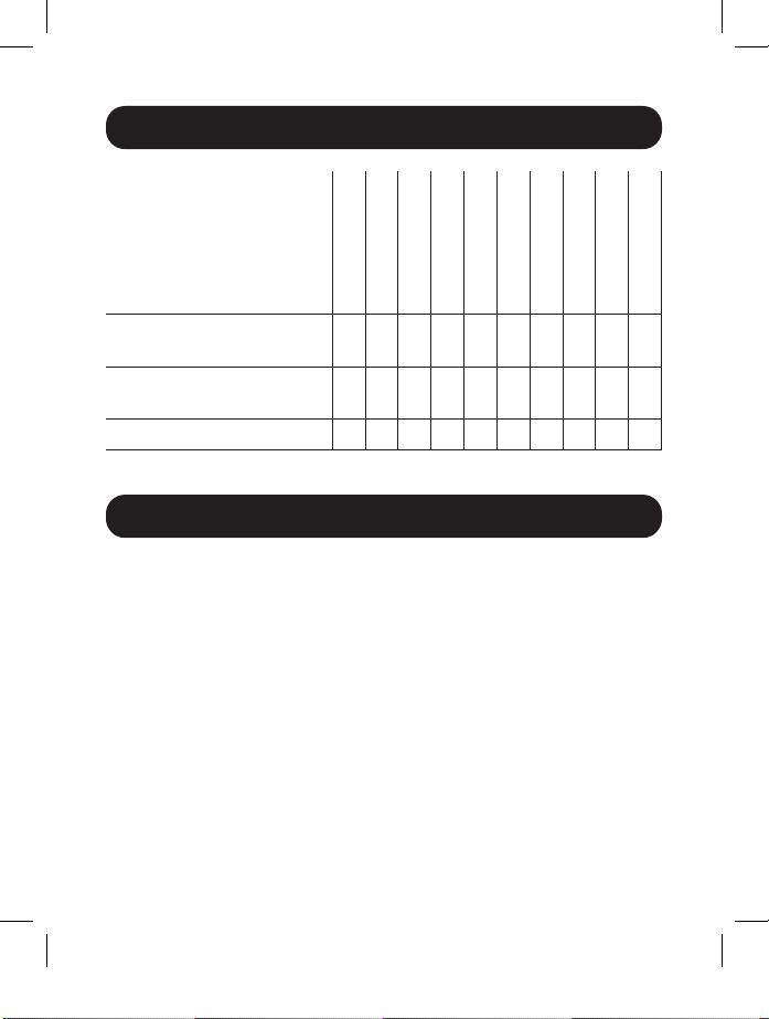
Package Contents
B127-1A1-HH
B127-2A1-HH
B127-002-2H2
B127-004-H4H
B127-002-H
B127-004-H
B127-008-H
B127-100-H
Local Unit (L),
Remote Unit (R) or Both (B)
External Power Supplies
(0 or 1)
Mounting Hardware Y Y Y Y Y Y Y Y Y N
B B B B L L L R R R
1 1 1 1 1 1 1 0 0 0
Product Features
All
• Support a maximum video resolution of 4K (3840 x 2160) @
60 Hz with 4:4:4 Chroma Subsampling
• Support up to 7.1-channel surround sound audio
• HDMI 2.0, HDCP 2.2 and HDR compatible
• Plug and play—no software or drivers required
B127-200-H
B127-100-H-SR
2
Page 3

Product Features
B127-1A1-HH
• HDMI over Cat6 Power-over-Cable (PoC) Extender Kit
• Extends a 4K (3840 x 2160) @ 60 Hz signal up to 125 ft. (38 m)
from the source
• Built-in local HDMI port supports multi-resolution technology, enabling
the connection of local monitors of various resolutions without affecting
the extended 4K @ 60 Hz signal to connected 4K-compatible displays
• Remote receiver unit features built-in equalization (EQ) control and
auto EDID image adjustment
• Includes mounting hardware that enables both the local transmitter
and remote receiver units to be wall-mounted, rack-mounted or polemounted
B127-2A1-HH
• HDMI over Cat6 Power-over-Cable (PoC) Extender Kit
• Extends a 4K (3840 x 2160) @ 60 Hz signal up to 125 ft. (38 m)
from the source
• Built-in local HDMI port supports multi-resolution technology, enabling
the connection of local monitors of various resolutions without affecting
the extended 4K @ 60 Hz signal to connected 4K-compatible displays
• Remote receiver unit features two HDMI output ports with built-in
equalization (EQ) control and auto EDID image adjustment
• Includes mounting hardware that enables both the local transmitter
and remote receiver units to be wall-mounted, rack-mounted or polemounted
3
Page 4

Product Features
B127-002-2H2
• HDMI over Cat6 Power-over-Cable (PoC) 2-Port Splitter/Extender Kit
• Extends a 4K (3840 x 2160) @ 60 Hz signal up to 125 ft. (38 m)
from the source
• Remote receiver unit features built-in equalization (EQ) control and
auto EDID image adjustment
• Kit includes a 2-Port Splitter Extender and two Remove Receivers
• Includes mounting hardware that allows unit to be wall-mounted,
rack-mounted or pole-mounted
B127-004-H4H
• HDMI over Cat6 Power-over-Cable (PoC) 4-Port Splitter/Extender Kit
• Extends a 4K (3840 x 2160) @ 60 Hz signal up to 125 ft. (38 m)
from the source
• Remote receiver unit features built-in equalization (EQ) control and
auto EDID image adjustment
• Kit includes a 4-Port Splitter Extender and four Remote Receivers
• Includes mounting hardware that allows unit to be wall-mounted,
rack-mounted or pole-mounted
• Built-in local HDMI port supports multi-resolution technology, enabling
the connection of local monitors of various resolutions without affecting
the extended 4K @ 60 Hz signal to connected 4K-compatible displays
B127-002-H
• 2-Port HDMI over Cat6 Extender/Splitter Local Transmitter Unit
• Splits an HDMI signal into two
• Works with remote receiver units to extend an HDMI signal past the
15 ft. (4.5 m) distance limitation
4
Page 5

Product Features
• Includes mounting hardware that allows unit to be wall-mounted,
rack-mounted or pole-mounted
B127-004-H
• 4-Port HDMI over Cat6 Extender/Splitter Local Transmitter Unit
• Splits an HDMI signal into four
• Built-in local HDMI port supports multi-resolution technology, enabling
the connection of local monitors of various resolutions without affecting
the extended 4K @ 60 Hz signal to connected 4K-compatible displays;
this port can also be used to daisy-chain additional B127-004-H units
(up to three units can be daisy-chained together)
• Works with remote receiver units to extend an HDMI signal past
the 15 ft. (4.5 m) distance limitation
• Includes mounting hardware that allows unit to be wall-mounted,
rack-mounted or pole-mounted
B127-008-H
• 8-Port HDMI over Cat6 Extender/Splitter Local Transmitter Unit
• Splits an HDMI signal into eight
• Built-in local HDMI port supports multi-resolution technology, enabling
the connection of local monitors of various resolutions without affecting
the extended 4K @ 60 Hz signal to connected 4K-compatible displays;
this port can also be used to daisy-chain additional B127-008-H units
(up to three units can be daisy-chained together)
• Works with remote receiver units to extend an HDMI signal past the
15 ft. (4.5 m) distance limitation
• Includes mounting hardware that allows unit to be wall-mounted,
rack-mounted or pole-mounted
5
Page 6

Product Features
B127-100-H
• HDMI over Cat6 Power-over-Cable (PoC) Remote Receiver Unit
• Works with B127-002-H and B127-004-H extender/splitters to
extend a 4K/60 Hz signal up to 125 ft. (38 m) from the source
• Built-in equalization (EQ) and EDID allows control for auto image
adjustment
• Includes mounting hardware that allows unit to be wall-mounted,
rack-mounted or pole-mounted
B127-200-H
• HDMI over Cat6 Power-over-Cable (PoC) Remote Receiver Unit
• Works with B127-002-H and B127-004-H extender/splitter units to
extend a 4K @ 60 Hz signal up to 125 ft. (38 m) from the source
• Built-in equalization (EQ) and EDID allows control for auto image
adjustment
• Includes mounting hardware that enables unit to be wall-mounted,
rack-mounted or pole-mounted
• Supports up to two HDMI Displays
B127-100-H-SR
• HDMI over Cat6 Power-over-Cable (PoC) Short Distance Remote
Receiver Unit
• Works with B127-002-H and B127-004-H extender/splitters to
extend a 4K/60 Hz signal up to 50 ft. (15 m) from the source
• Built-in equalization (EQ) and EDID allows control for auto image
adjustment
Optional Accessories:
• N202-Series Cat6 24 AWG Solid-Wire Patch Cables
• P569-XXX-CERT or P568-XXX-2A Series High-Speed HDMI 2.0 Cables
6
Page 7

Disclaimer
Before installation, please check the following settings of your source(s)
and TV/monitor(s):
1. Set to display 60 Hz. Double-check factory settings, as default can
be set to a lower frequency (Hz) than advertised.
2. Ensure the input setting of your monitor is set at HDMI 2.0. Some
displays may have default setting at HDMI 1.4
3. Verify your monitor has the HDR feature enabled. Some displays
may have this feature disabled as a factory setting.
4. Check if the Ultra HD (UHD) Deep Color setting is enabled on your TV/
monitor. Confirm with your TV/monitor manufacturer which HDMI ports
support UHD Deep Color.
Note: To connect a local monitor to your installation, the UHD Deep Color setting
may need to be disabled on your local TV/monitor (depending make/mode) to
achieve 4K 60 Hz resolution.
7
Page 8

Mounting Instructions (select models only)
The B127-1A1-HH, B127-2A1-HH, B127-002-2H2, B127-004-H4H,
B127-002-H, B127-004-H, B127-008-H, B127-100H and B127-200H
include includes mounting hardware that allows for a variety of mounting
methods. The following images illustrate how the included mounting
brackets can be attached for different installations.
Note: The model shown in the below images is for illustrative purposes only. Your
product may vary by model number, size or port orientation. The mounting options
for all over IP units are the same.
Wall-mount
19" Rack-mount Pole-mount
8
Page 9

Standard Extender Kit Installation
Installation Instructions for B127-1A1-HH
Notes:
1) Test to ensure the entire installation works properly before pulling cables through
ceilings/walls.
2) To achieve maximum distance and performance, use 24 AWG solid-wire Cat6
cable. Using stranded-wire Cat6 cable, or cable with a gauge (AWG) size higher
than 24 AWG, will result in shorter extension distance. Higher gauge cabling,
such as 26 AWG, has a more limited transmission capability than lower gauge
cabling. All Tripp Lite N202-Series Cat6 cables are made with 24 AWG solid-wire
cabling.
3) The installation diagram shows a B127-1A1-HH unit.
4) External power is not required for remote receiver units due to Power-over-Cable
(PoC) technology incorporated in the transmitter units.
1
OPTIONAL LOCAL
MONITOR HDR PLAYER
Up to 125 ft. (38 m) at 4K/60 Hz
LOCAL
TRANSMITTER
1. Make sure all equipment in the installation—such as TVs, Blu-ray
players and the transmitter—is powered OFF.
2. Using an HDMI 2.0 cable (such as Tripp Lite P569-XXX-CERT or
P568-XXX-2A Series cables), connect the HDMI source to the INPUT
port on the local transmitter unit.
Up to 125 ft. (38 m) Cat6 cable at 4K/60 Hz
2
Up to 15 ft. (4.5 m) HDMI 2.0 cable at 4K/60 Hz
REMOTE
RECEIVER
9
Page 10

Standard Extender Kit Installation
3. Optional for B127-1A1-HH: Using an HDMI 2.0 cable (such as
Tripp Lite P569-XXX-CERT or P568-XXX-2A Series cables), connect
a local monitor to the LOCALOUT port on the B127-1A1-HH local
transmitter unit.
Note: Monitors with lower resolutions such as 1080p or 4K @ 30 Hz can be
connected to the local HDMI port without affecting the 4K @ 60 Hz signal.
4. Using Cat6 cable, connect the RJ45 port on the local transmitter unit
to the RJ45 port on the remote receiver unit.
5. Using an HDMI 2.0 cable (such as Tripp Lite P569-XXX-CERT or
P568-XXX-2A Series cables), connect the remote receiver unit’s HDMI
port to a monitor.
6. Turn the power on to your connected TVs/monitors. The LOCAL
(orange) LED will illuminate to indicate local port has been connected
to a display.
7. Connect the external power supply to the local transmitter unit and
plug it into an available wall outlet or (optional) a Tripp Lite Surge
Protector, Power Distribution Unit (PDU) or Uninterruptible Power
Supply (UPS). The POWER (green) LED on the local transmitter unit
will illuminate to indicate the unit is receiving power from the external
power supply. The POWER (green) LED on the remote receiver unit
will illuminate to indicate the unit is receiving power from the local
transmitter unit through PoC technology.
8. Turn on the power to the HDMI source. The OUTPUT (orange) LED
on the local transmitter unit illuminates to indicate a signal is being
received from the source.
9. The (orange) RJ45 LED will illuminate on both local transmitter and
remote receiver units to indicate a signal is being received from
source to display. The screen should now display on the connected
monitor.
10
Page 11

Standard Extender/Splitter Installation
Installation Instructions for B127-2A1-HH
Notes:
1) Test to ensure the entire installation works properly before pulling cables through
ceilings/walls.
2) To achieve maximum distance and performance, use 24 AWG solid wire Cat6
cable. Using stranded-wire Cat6 cable, or cable with a gauge (AWG) size higher
than 24 AWG, will result in shorter extension distance. Higher gauge cabling,
such as 26 AWG, has a more limited transmission capability than lower gauge
cabling. All Tripp Lite N202-Series Cat6 cables are made with 24 AWG solid-wire
cabling.
3) The installation diagram shows a B127-2A1-HH unit.
4) External power is not required for remote receiver units because of Power-overCable (PoC) technology incorporated in the transmitter units.
1
B127-2A1-HH
extender kit
MONITOR HDR PLAYER
Up to 125 ft. (38 m) at 4K/60 Hz
LOCAL
TRANSMITTER
1. Make sure all equipment in the installation—such as TVs, Blu-ray
players and the transmitter—is powered OFF.
2. Using an HDMI 2.0 cable (such as Tripp Lite P569-XXX-CERT or
P568-XXX-2A Series cables), connect the HDMI source to the INPUT
port on the local transmitter unit.
Up to 125 ft. (38 m) Cat6 cable at 4K/60 Hz
2
Up to 15 ft. (4.5 m) HDMI 2.0 cable at 4K/60 Hz
REMOTE
RECEIVER
11
Page 12

Standard Extender/Splitter Installation
3. Optional for B127-2A1-HH: Using an HDMI 2.0 cable (such as
Tripp Lite P569-XXX-CERT or P568-XXX-2A Series cables), connect
a local monitor to the LOCALOUT port on the B127-2A1-HH local
transmitter unit.
Note: Monitors with varying resolutions like 1080p or 4K 30 Hz can be
connected to the local HDMI port without affecting the 4K @ 60 Hz signal.
4. Using Cat6 cable, connect the RJ45 port on the local transmitter unit
to the RJ45 port on the remote receiver unit.
5.
Using an HDMI 2.0 cable (such as Tripp Lite P569-XXX-CERT or
P568-XXX-2A Series cables), connect one of the remote receiver unit’s
HDMI ports to a monitor/TV and the other to a second monitor/TV.
6. Turn the power on to the connected TVs/monitors. The LOCAL
(orange) LED will illuminate to indicate the local port has been
connected to a display.
7. Connect the external power supply to the local transmitter unit and
plug it into an available wall outlet or a Tripp Lite Surge Protector,
Power Distribution Unit (PDU) or Uninterruptible Power Supply (UPS).
The POWER (green) LED on the local transmitter unit will illuminate
to indicate the unit is receiving power from the external power supply.
The POWER (green) LED on the remote receiver unit will illuminate
to indicate the unit is receiving power from the local transmitter unit
through PoC technology.
8. Turn on the power to the HDMI source. The OUTPUT (orange) LED
on the local transmitter unit illuminates to indicate a signal is being
received from the source.
9. The (orange) RJ45 LED will illuminate on both local transmitter and
remote receiver units to indicate a signal is being received from
source to display. The screen should now display on the connected
monitor(s).
12
Page 13

Standard Extender/Splitter Installation
Notes:
1) Test to ensure the entire installation works properly before pulling cables through
ceilings/walls.
2) To achieve maximum distance and performance, use 24 AWG solid-wire Cat6
cable. Using stranded-wire Cat6 cable, or cable with a gauge (AWG) size higher
than 24 AWG, will result in shorter extension distance. Higher gauge cabling,
such as 26 AWG, has a more limited transmission capability than lower gauge
cabling. All Tripp Lite N202-Series cables are made with 24 AWG solid-wire
cabling.
3) The installation diagram shows the B127-004-H local transmitter unit. The
B127-002-H installation is the same, except there are only two remote ports
and no local monitor port. The B127-008-H features eight remote ports and
one local monitor port.
4) External power is not required for the B127-100-H, B127-100-H-SR and
B127-200-H units.
5) These installation instructions can be used for the B127-002-2H2 and
B127-004-H4H extender kits.
1
B127-004-H4H
extender kit
Up to 125 ft. (38 m) Cat6 cable at 4K/60 Hz
2
Up to 50 ft. (15 m) Cat6 cable at 4K/60 Hz
3
Up to 15 ft. (4.5 m) HDMI 2.0 cable at 4K/60 Hz
OPTIONAL
LOCAL MONITOR
B127-100-H
B127-100-H-SR
B127-100-H-SR
B127-100-H
B127-004-H
HDR PLAYER
13
Page 14

Standard Extender/Splitter Installation
1. Make sure all equipment in the installation—such as TVs, Blu-ray
players and the transmitter—is powered OFF.
2. Using an HDMI 2.0 cable (such as Tripp Lite P569-XXX-CERT or
P568-XXX-2A Series cables), connect the HDMI source to the INPUT
port on the B127-002-H or B217-004-H units.
3. Optional for B127-004-H and B127-008H: Using an HDMI 2.0
cable (such as Tripp Lite P569-XXX-CERT or P568-XXX-2A Series
cables), connect an HDMI monitor to the LOCAL port on the
B127-004-H or B127-008H unit.
Note: Monitors with varying resolutions like 1080p or 4K 30 Hz can be
connected to the local HDMI port without affecting the 4K @ 60 Hz signal.
4. Using Cat6 cable, connect one of the RJ45 output ports on the local
transmitter unit to the RJ45 input port on a B127-100-H (up to
125 ft./38 m), B127-100-H-SR (up to 50 ft./15 m) or B127-200-H
(up to 125 ft./38 m) remote receiver unit.
5. Repeat step 5 for each additional remote unit being connected.
6. Using an HDMI 2.0 cable (such as Tripp Lite P569-XXX-CERT or
P568-XXX-2A Series cables). Connect the B127-100-H,
B127-100-H-SR or B127-200-H to a display.
7. Turn on the power to all your connected TVs or monitors. The LOCAL
(orange) LED will illuminate to indicate the port has been connected
to a display.
8. Connect the external power supply to the local transmitter unit and
plug it into an available wall outlet or (optional) a Tripp Lite Surge
Protector, Power Distribution Unit (PDU) or Uninterruptible Power
Supply (UPS). The POWER (green) LED will illuminate to indicate
the unit is receiving power from the external power supply. On the
B127-100-H and B127-200-H, the POWER (green) LED will
illuminate to indicate the unit is receiving power from the extender/
splitter. On the B127-100-H-SR, the (green) LED next to the RJ45
14
Page 15

Standard Extender/Splitter Installation
port will illuminate to indicate the unit is receiving power from the
extender/splitter.
9. Turn on the power to the HDMI source. The (orange) RJ45 LEDs will
illuminate on the B127-002-H , B127-004-H and B127-008H to
indicate the unit is receiving a signal from the source. Additionally, the
OUTPUT (orange) LED will illuminate for each port signal connection.
10. The RJ45 (orange) LEDs on the B127-100-H / B127-200-H and
orange LED on the B127-100-H-SR will illuminate to indicate a signal
is being received from the extender/splitter. The screen should now
display on the connected monitors.
Splitter Daisy-Chain Installation
(B127-004-H and B127-008H only)
Notes:
1) Test to ensure the entire installation works properly before pulling cables through
ceilings/walls.
2) To achieve maximum distance and performance, use 24 AWG solid-wire Cat6
cable. Using stranded-wire Cat6 cable, or cable with a gauge (AWG) size higher
than 24 AWG, will result in shorter extension distance. Higher gauge cabling,
such as 26 AWG, has a more limited transmission capability than lower gauge
cabling. All Tripp Lite N202-Series cables are made with 24 AWG solid-wire
cabling.
3) Using the B127-100-H or the B127-200-H, a 4K/60 Hz signal can be extended
up to 125 ft. (38 m) from the source. Using a B127-100-H-SR, a 4K/60 Hz
signal can be extended up to 50 ft. (15 m) from the source.
4) The B127-200-H supports two HDMI output ports.
15
Page 16

Splitter Daisy-Chain Installation
(B127-004-H and B127-008H only)
1
Up to 125 ft. (38 m) Cat6 cable at 4K/60 Hz
2
Up to 50 ft. (15 m) Cat6 cable at 4K/60 Hz
3
Up to 15 ft. (4.5 m) HDMI 2.0 cable at 4K/60 Hz
4
Up to 6 ft. (1.8 m) HDMI 2.0 cable at 4K/60 Hz
Level 1
HDR PLAYER
B127-004-H
Level 2
Level 3
OPTIONAL
LOCAL
MONITOR
B127-004-H
B127-004-H
16
Page 17

Splitter Daisy-Chain Installation
(B127-004-H and B127-008H only)
1. Make sure all equipment in the installation—such as TVs, Blu-ray
players and the transmitter—is powered OFF.
2. Using an HDMI 2.0 cable (such as Tripp Lite P569-XXX-CERT or
P568-XXX-2A Series cables), connect the HDMI source to the INPUT
port on the B127-004-H or B127-008H unit.
3. Using a 6 ft./1.83 m HDMI 2.0 cable (such as Tripp Lite
P569-006-CERT or P568-006-2A cables), connect the LOCAL port
on the B127-004-H or B127-008H to the INPUT port on a second
B127-004-H or B127-008H unit.
4. Repeat step 3 if connecting a third B127-004-H or B127-008H unit.
Note: Only three levels of splitters can be cascaded.
5. Optional: Using an HDMI 2.0 cable (such as Tripp Lite
P569-XXX-CERT or P568-XXX-2A Series cables), connect a local
monitor to the LOCAL HDMI port of the last B127-004-H unit in the
installation.
Note: Monitors with varying resolutions like 1080p or 4K 30 Hz can be
connected to the local HDMI port without affecting the 4K @ 60 Hz signal.
6. Using Cat6 cable, connect one of the RJ45 output ports on the local
transmitter units to the RJ45 input port on a B127-100-H,
B127-200-H or B127-100-H-SR remote receiver unit.
7. Repeat step 6 for each additional remote unit being connected.
8. Using an HDMI 2.0 cable (such as Tripp Lite P569-XXX-CERT or
P568-XXX-2A Series cables), connect the B127-100-H, B127-200-H
or B127-100-H-SR to a display.
9. Repeat step 8 for each additional monitor you are connecting to a
remote receiver unit.
10. Turn on the power to all your connected displays.
17
Page 18

Splitter Daisy-Chain Installation
(B127-004-H and B127-008H only)
11. Connect the external power supply to the local transmitter unit and
plug it into an available wall outlet or (optional) a Tripp Lite Surge
Protector, Power Distribution Unit (PDU) or Uninterruptible Power
Supply (UPS). The POWER (green) LED will illuminate to indicate the
unit is receiving power from the external power supply.
12. Repeat step 11 for each additional B127-004-H or B127-008H unit
in the daisy chain.
13. B127-000-H, B127-100-H-SR and B127-200-H: The green and
orange LEDs will illuminate, with the green LED indicating the unit
is receiving power from the extender/splitter, and the orange LED
indicating the unit is connected to a powered ON local unit via Cat6
cable.
14. Turn on the power to the HDMI source. The orange RJ45 LEDs will
illuminate on the B127-004-H or B127-008H to indicate the unit is
receiving a signal from the source. The screen should now display on
the connected monitors.
18
Page 19

Warranty and Product Registration
1-Year Limited Warranty
TRIPP LITE warrants its products to be free from defects in materials and
workmanship for a period of one (1) year from the date of initial purchase.
TRIPP LITE’s obligation under this warranty is limited to repairing or replacing (at its
sole option) any such defective products. To obtain service under this warranty, you
must obtain a Returned Material Authorization (RMA) number from TRIPP LITE or
an authorized TRIPP LITE service center. Products must be returned to TRIPP LITE
or an authorized TRIPP LITE service center with transportation charges prepaid and
must be accompanied by a brief description of the problem encountered and proof
of date and place of purchase. This warranty does not apply to equipment which
has been damaged by accident, negligence or misapplication or has been altered or
modified in any way.
EXCEPT AS PROVIDED HEREIN, TRIPP LITE MAKES NO WARRANTIES, EXPRESS OR
IMPLIED, INCLUDING WARRANTIES OF MERCHANTABILITY AND FITNESS FOR A
PARTICULAR PURPOSE. Some states do not permit limitation or exclusion of implied
warranties; therefore, the aforesaid limitation(s) or exclusion(s) may not apply to the
purchaser.
EXCEPT AS PROVIDED ABOVE, IN NO EVENT WILL TRIPP LITE BE LIABLE FOR
DIRECT, INDIRECT, SPECIAL, INCIDENTAL OR CONSEQUENTIAL DAMAGES ARISING
OUT OF THE USE OF THIS PRODUCT, EVEN IF ADVISED OF THE POSSIBILITY OF
SUCH DAMAGE. Specifically, TRIPP LITE is not liable for any costs, such as lost
profits or revenue, loss of equipment, loss of use of equipment, loss of software,
loss of data, costs of substitutes, claims by third parties, or otherwise.
PRODUCT REGISTRATION
Visit tripplite.com/warranty today to register your new Tripp Lite product. You’ll be
automatically entered into a drawing for a chance to win a FREE Tripp Lite product!*
* No purchase necessary. Void where prohibited. Some restrictions apply. See website for details.
19
Page 20

Warranty and Product Registration
WEEE Compliance Information for Tripp Lite Customers and Recyclers
(European Union)
Under the Waste Electrical and Electronic Equipment (WEEE) Directive and
implementing regulations, when customers buy new electrical and electronic
equipment from Tripp Lite they are entitled to:
• Send old equipment for recycling on a one-for-one, like-for-like basis
(this varies depending on the country)
• Send the new equipment back for recycling when this ultimately becomes
waste
WARNING
Use of this equipment in life support applications where failure of this equipment
can reasonably be expected to cause the failure of the life support equipment or to
significantly affect its safety or effectiveness is not recommended.
Tripp Lite has a policy of continuous improvement. Specifications are subject to
change without notice. Photos and illustrations may differ slightly from actual
products.
1111 W. 35th Street, Chicago, IL 60609 USA • tripplite.com/support
20
20-02-371 93-3918_RevC
 Loading...