

Page 1

WARRANTY
REGISTRATION:
register online today for a
chance to win a FREE Tripp Lite
product—www.tripplite.com/warranty
8-User Matrix KVM Switch
Owner’s Manual
NetDirector™ 32-Port
Model: B060-032-8
1111 W. 35th Street, Chicago, IL 60609 USA
(773) 869-1234 • www.tripplite.com
Copyright © 2008 Tripp Lite. All rights reserved. All trademarks are the property of their respective owners.
1
Page 2

Table of Contents
1. Introduction. . . . . . . . . . . . . . . . . . . . . . . . . . . . . . . . . . . Page 2
2. Important Safety Instructions . . . . . . . . . . . . . . . . . . . . . . . . . 3
3. System Components . . . . . . . . . . . . . . . . . . . . . . . . . . . . . . . . 4
4. Compatibility & Required Hardware . . . . . . . . . . . . . . . . . . . . 4
4.1 Compatibility . . . . . . . . . . . . . . . . . . . . . . . . . . . . . . . . . . . . 4
4.2 Required Hardware. . . . . . . . . . . . . . . . . . . . . . . . . . . . . . . 4
5. Features. . . . . . . . . . . . . . . . . . . . . . . . . . . . . . . . . . . . . . . . . . . 5
6. Rackmounting. . . . . . . . . . . . . . . . . . . . . . . . . . . . . . . . . . . . . . 6
7. Single-Level Installation. . . . . . . . . . . . . . . . . . . . . . . . . . . . . . 7
8. Multilevel Installation . . . . . . . . . . . . . . . . . . . . . . . . . . . . . . . . 8
8.1 Cascading . . . . . . . . . . . . . . . . . . . . . . . . . . . . . . . . . . . . 8
8.2 Daisy-Chaining . . . . . . . . . . . . . . . . . . . . . . . . . . . . . . . 11
9. Basic Operation . . . . . . . . . . . . . . . . . . . . . . . . . . . . . . . . . . . 12
10. Administrator Utility . . . . . . . . . . . . . . . . . . . . . . . . . . . . . . . 12
10.1 Network Installation . . . . . . . . . . . . . . . . . . . . . . . . . . . 12
10.13 User Management. . . . . . . . . . . . . . . . . . . . . . . . . . . . . 22
10.14 Port Management . . . . . . . . . . . . . . . . . . . . . . . . . . . . . 25
10.15 Setting the OSD View . . . . . . . . . . . . . . . . . . . . . . . . . . 27
10.16 Searching for Ports & Stations . . . . . . . . . . . . . . . . . . 30
10.17 Upgrading Firmware. . . . . . . . . . . . . . . . . . . . . . . . . . . 30
10.18 Replacing the Root B060-032-8 . . . . . . . . . . . . . . . . . . 33
10.19 Backing Up & Restoring Settings . . . . . . . . . . . . . . . . 34
10.20 Viewing & Ending User Sessions . . . . . . . . . . . . . . . . 34
10.21 Viewing System Information & Help . . . . . . . . . . . . . . 36
10.22 Logging Out . . . . . . . . . . . . . . . . . . . . . . . . . . . . . . . . . 36
11. OSD Operation . . . . . . . . . . . . . . . . . . . . . . . . . . . . . . . . . . . 36
11.1 OSD Main Screen . . . . . . . . . . . . . . . . . . . . . . . . . . . . . 36
11.2 OSD Navigation . . . . . . . . . . . . . . . . . . . . . . . . . . . . . . 37
11.3 Accessing Switches & Computers . . . . . . . . . . . . . . . 38
11.4 OSD Functions . . . . . . . . . . . . . . . . . . . . . . . . . . . . . . . 39
10.2 Topology Considerations . . . . . . . . . . . . . . . . . . . . . . 13
10.3 Setting the IP Address . . . . . . . . . . . . . . . . . . . . . . . . . 13
10.4 Logging In . . . . . . . . . . . . . . . . . . . . . . . . . . . . . . . . . . . 14
10.5 Menus & Icons . . . . . . . . . . . . . . . . . . . . . . . . . . . . . . . 16
10.6 Port Status . . . . . . . . . . . . . . . . . . . . . . . . . . . . . . . . . . 17
10.7 Naming Stations . . . . . . . . . . . . . . . . . . . . . . . . . . . . . . 17
10.8 Setting the Web Page Session Timeout . . . . . . . . . . . 18
10.9 Network Confi guration. . . . . . . . . . . . . . . . . . . . . . . . . 18
10.10 IP Installer Setting . . . . . . . . . . . . . . . . . . . . . . . . . . . . 19
10.11 Setting Date & Time . . . . . . . . . . . . . . . . . . . . . . . . . . . 20
10.12 Group Management . . . . . . . . . . . . . . . . . . . . . . . . . . . 20
11.5 Management Menus . . . . . . . . . . . . . . . . . . . . . . . . . . . 41
12. Hotkey Mode . . . . . . . . . . . . . . . . . . . . . . . . . . . . . . . . . . . . . 44
12.1 Invoking Hotkey Mode . . . . . . . . . . . . . . . . . . . . . . . . . 45
12.2 Hotkey Port Switching . . . . . . . . . . . . . . . . . . . . . . . . . 45
12.3 Hotkey Beeper Control. . . . . . . . . . . . . . . . . . . . . . . . . 46
12.4 Keyboard Emulation. . . . . . . . . . . . . . . . . . . . . . . . . . . 46
13. Troubleshooting . . . . . . . . . . . . . . . . . . . . . . . . . . . . . . . . . . 47
14. Specifi cations . . . . . . . . . . . . . . . . . . . . . . . . . . . . . . . . . . . . 48
15. Storage & Service. . . . . . . . . . . . . . . . . . . . . . . . . . . . . . . . . 49
16. Warranty & Warranty Registration. . . . . . . . . . . . . . . . . . . . 49
1. Introduction
Tripp Lite’s NetDirector™ Matrix KVM Switch (Model B060-032-8) enables eight consoles to independently and simultaneously control up to 32 directly
connected computers. The installation can be expanded to over 8000 computers/servers via a combination of daisy chaining and cascading. Premium
features include:
• Eight consoles independently and simultaneously control up to 32 directly connected computers, and hundreds of computers/servers connected via
cascaded B060-032-8 KVM switches
• Cascade up to 3 levels of B060-032-8 and 1 level of B007-008 KVM switches to support over 8,000 computers/servers
• Back up and restore settings when changing root stations
• Web-based B060-032-8 Administrator Utility simplifi es confi guration and maintenance of the KVM installation
• Three levels of user access control (Super Administrator, Administrator, and User)
2
Page 3

1. Introduction
• Super Administrators can view and end sessions of other users
• Super Administrators can broadcast keyboard input to all computers in the KVM installation
• Supports password authentication
• Additional user port on front panel for easy system maintenance
• Hot pluggable—add or remove components without having to power off the KVM switch
• Multiplatform support—PC, Mac and serial
• Multi-architecture compatibility—PC (x86/x64), Macintosh PowerPC
• Supports up to 1024 user accounts and up to 256 group accounts
• Automatic video routing technology enables multiple consoles to access separate ports in cascaded/daisy-chained KVM Switches at the same time
• Convenient computer selection via intuitive hotkey combinations or On Screen Display (OSD) menus
• Auto-sensing of station’s position on daisy-chain installations; OSD and front panel LED indicates station’s position
• Port names are automatically reconfi gured when the station sequence is changed
• Auto Scan feature for monitoring user-selected computers
• PS/2 keyboard and mouse emulation—computers boot even when the KVM console focus is elsewhere
• LCD, VGA, SVGA, XGA, and MultiSync support; DDC2B
• Superior video quality – 1024 x 768 @ 60Hz for up to 300 m; 1920 x 1440 @ 60Hz (distance depends on installation environment)
• Auto Signal Compensation (ASC) assures optimum video resolution for distances up to 300 m between computers and KVM consoles—no DIP switch
setting required
2. Important Safety Instructions
SAVE THESE INSTRUCTIONS
This manual contains instructions and warnings that should be followed during the installation and operation of this product. Failure to comply may
invalidate the warranty and cause property damage and/or personal injury.
Installation Warnings
• Install the KVM switch in a controlled indoor environment, away from moisture, temperature extremes, fl ammable liquids and gasses, conductive
contaminants, dust and direct sunlight.
• Operate the KVM switch at indoor temperatures between 32° F and 104° F (0° C and 40° C).
• When connecting the KVM switch to the facility’s power supply circuit, ensure that the circuit is not overloaded.
Rackmount Warnings
• Ensure there is adequate airfl ow within the rack.
• Mount the KVM switch evenly within the rack to eliminate potentially hazardous uneven mechanical loading conditions.
• Ensure that all rackmount equipment is reliably grounded.
Connection Warnings
• Use of this equipment in life support applications where failure of this equipment can reasonably be expected to cause the failure of the life support
equipment or to signifi cantly affect its safety or effectiveness is not recommended. Do not use this equipment in the presence of a fl ammable anesthetic
mixture with air, oxygen or nitrous oxide.
• Ensure that the cables used with the KVM switch are not close to any sources of electrical noise interference such as fl uorescent lights, HVAC systems or
motors.
• Ensure that the distance between any computer and the KVM switch does not exceed 33 ft. (10m).
• Shut down all PS/2 computers before connecting the keyboard, monitor and mouse to ensure that they will be recognized by the computer.
Maintenance Warnings
• The KVM switch does not require routine maintenance. There are no user-serviceable parts inside. Only authorized service personnel should open the
case for any reason. Disconnect the unit from AC input power before servicing.
3
Page 4

3. System Components
The NetDirector Matrix KVM Switch consists of:
• B060-032-8 Matrix KVM Switch
• 1 Power Cord
• 1 Rackmount Kit
• 1 Set of Foot Pads
4. Compatibility & Required Hardware
4.1 Compatibility
Operating System Version Supported
Windows 2000 and higher
Linux RedHat 6.0 and higher
Linux SuSE 8.2 and higher
Linux Mandriva (Mandrake) 9.0 and higher
UNIX AIX 4.3 and higher
UNIX FreeBSD 3.51 and higher
UNIX Sun Solaris 8 and higher
Novell Netware 5.0 and higher
Mac OS 9 and higher
OS/2 Warp Ver. 2
DOS 6.22
4.2 Required Hardware
For KVM Consoles
The following hardware components are required for each KVM console:
• A VGA, SVGA, or MultiSync monitor capable of displaying the highest resolution provided by any computer in the installation
• Keyboard and mouse (PS/2 or USB)
For Connected Computers/Servers
The following hardware components are required for each computer:
• An HD15 VGA port
• PS/2 mouse and keyboard ports (MiniDIN6) or one USB port
Required Cables & Interface Units
Console Interface Units (CIUs) are required to connect consoles to the B060-032-8. Server Interface Units (SIUs) are required to connect multiplatform
computers and certain cascaded KVM switches to the B060-032-8. The following table lists the Console Interface Units (CIUs), Server Interface Units
(SIUs) and cables available for the B060-032-8.
Function CIU, SIU or Cable Required
Connecting a PS/2 KVM Console to a B060-032-8 B062-002-PS2 Console Interface Unit
Connecting a USB KVM Console to a B060-032-8 B062-002-USB Console Interface Unit
Connecting B060-032-8 to a PS/2 Server B054-001-PS2 Server Interface Unit
Connecting B060-032-8 to a USB Server B054-001-USB Server Interface Unit
Connecting CIUs and SIUs to B060-032-8, or cascading to Cat5 Cable (Tripp Lite N001-, N002- and N105 Series Cat5 Cables)
another B060-032-8
Daisy-Chaining to a B060-032 or B060-016-2 Daisy-Chain Cable included with B060-032 and B060-016-2.
Use Tripp Lite P770-Series Daisy-Chain cables for longer cable lengths.
4
Page 5
5. Features
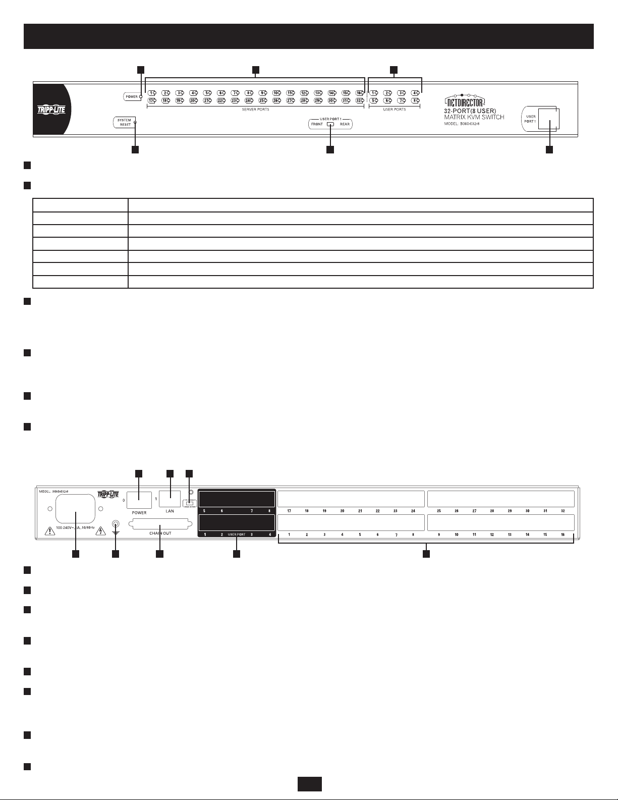
B060-032-8 Front View
1
Power LED: Lights (blue) to indicate that the unit is receiving power.
2
Server Port LEDs:
1 2 3
4 5 6
Port LED Status
Steady Amber Light KVM Port is selected and the connected computer is powered on
Flashing Amber Light KVM Port is selected and is cascaded to a powered on KVM Switch
Steady Green Light KVM Port is not selected and the connected computer is powered on
Flashing Green Light KVM Port is not selected and is cascaded to a powered on KVM Switch
Steady Red Light KVM Port is selected and the connected computer is powered off
No Light KVM Port is not selected and the connected computer is powered off; or there is no computer connected to the KVM Port
3
User Port LEDs:
• Illuminates (green) to indicate that the console module connected to the corresponding user port is online.
• Flashes when cascaded from the KVM port(s) of a parent KVM switch.
4
Reset Button: Press to perform a system reset.* When the system is reset, the B060-032-8 beeps, and the KVM port LEDs fl ash in succession until the
reset is completed. After the reset is completed you can log in again.
* This button is semi-recessed and must be pushed with a thin object such as the end of a paper clip or a ballpoint pen.
5
USER PORT 1 Switch: This switch selects which USER PORT 1 port is active (front panel or rear panel). Set to FRONT to activate the USER PORT 1
port on the front panel; set it to REAR to activate the USER PORT 1 port on the rear panel.
6
USER PORT 1 Maintenance Port: Provides convenient access when performing system maintenance. It shares the same function with the USER PORT
1 port on the rear panel. Switching the USER PORT 1 switch to FRONT deactivates the USER PORT 1 port on the rear panel and activates the USER
PORT 1 port on the front panel. (USER PORT 1 switch must be returned to the REAR position to reactivate the USER PORT 1 port on the rear panel.)
B060-032-8 Rear View
1 5 6 7 8
1
Power Socket: The unit’s AC power cord plugs in here.
2
Power Switch: Standard rocker switch powers the KVM switch on and off.
3
LAN Port: Connects the KVM Switch to the local network, providing access to the B060-032-8 Administrator Utility to confi gure the KVM installation,
2 3 4
create and manage user and group accounts, set device access permissions, upgrade fi rmware, etc.
4
Firmware Upgrade Switch: Place this switch in the NORMAL position during normal operation and while performing a fi rmware upgrade. If a fi rmware
upgrade operation does not complete successfully, this switch is used to perform a fi rmware upgrade recovery.
5
Grounding Terminal: The grounding wire used to ground the unit attaches here.
6
DAISY-CHAIN OUT Port: When daisy-chaining KVM switches, the DAISY-CHAIN OUT port is used to connect the lower-level KVM switches in the
chain.
* If this feature is not operational, your unit requires updated fi rmware. Contact your dealer for assistance or check for the latest fi rmware in the Support Section at www.tripplite.com.
7
User Ports: Cat5 cables from the console modules plug in here. USER PORT 1 shares KVM access with USER PORT 1 on the front panel. The USER
PORT 1 switch (front panel) controls which of the two ports is active.
8
Server Ports: Cat5 cables linking the Server Interface Units (SIUs) to the B060-032-8 plug in here.
5
Page 6

6. Rackmounting
Stacking and Rackmounting
• The included rackmounting kit does not contain screws or cage nuts for attaching the B060-032-8 to your rack. If you need additional screws or cage nuts,
contact your rack dealer.
• Allow at least 2 in. (5.1cm) on each side for adequate ventilation and 5 in. (12.7cm) at the rear for power cord and cable clearance.
Rackmounting Safety Instructions
• Prior to installation, ensure that stabilizers are secured to the rack, extended to the fl oor, and that the full weight of the rack rests on the fl oor. Install front
and side stabilizers on a single rack or front stabilizers for joined multiple racks before working on the rack.
• Always load the rack from the bottom up, and load the heaviest item in the rack fi rst.
• Make sure that the rack is level and stable before extending a device from the rack.
• Do not overload the AC supply branch circuit that provides power to the rack. The total rack load should not exceed 80% of the branch circuit rating.
• Make sure that all rack equipment, including power strips and other electrical connectors, is properly grounded.
• Ensure that proper airfl ow is provided to devices in the rack.
• Ensure that the operating ambient temperature of the rack environment does not exceed the maximum ambient temperature specifi ed for the equipment by
the manufacturer (0° to 50° Celsius, 32° to 122° Fahrenheit).
• Do not step on or stand on any device when servicing other devices in a rack.
Stacking
The B060-032-8 can be placed on any level surface that will safely support its weight plus the weight of attached cables. Ensure that the surface is clean and
free of materials that could block the exhaust vents or otherwise interfere with normal operation of the unit. A foot pad set is included with the unit. Peel the
protective backing off of the foot pads and affi x them to the corners of the bottom panel of the unit.
Front Rackmounting
1
Remove the screws located on each side of the front of the unit.
2
Use the Phillips head hex screws supplied with the rackmounting kit to screw the mounting brackets into the sides at the front of the unit.
3
Place the KVM switch in the rack. Position it so that the holes in the mounting brackets line up with the holes in the rack. Secure the mounting brackets to
the front of the rack.
Rear Rackmounting
1
Remove the screws located on each side of the rear of the unit.
2
Use the Phillips head hex screws supplied with the rack mounting kit to screw the rack mounting brackets into the sides at the rear of the unit.
3
Place the KVM switch in the rack. Position it so that the holes in the mounting brackets line up with those in the rack. Secure the mounting brackets to the
rear of the rack.
Grounding
To prevent damage to your KVM switch, it is important to ensure that all devices are properly grounded. Use a grounding wire to ground the B060-032-8 by
connecting one end of the wire to the grounding terminal and the other end to a suitable grounded object.
6
Page 7

7. Single-Level Installation
Note: Prior to installation, ensure that all devices being connected to the B060-032-8 are powered off.
In a single-level installation, there are no additional KVM switches cascaded or daisy-chained from the B060-032-8. To set up a single-level installation,
refer to the following steps:
1
Connect the console to the Console Interface Unit (CIU). Select the appropriate CIU for the console you are installing. (See chart on page 4 for more
information.) Plug your keyboard, mouse, and monitor into their respective ports on the CIU. Each port is identifi ed with an icon.
2
Connect the CIU to the B060-032-8. Use Cat5 cable to connect the Link port of the CIU to one of the user ports on the B060-032-8 rear panel. (Repeat
1 2
and for all KVM consoles that you wish to connect. Up to eight KVM consoles may be connected in this manner.) The distance between the
B060-032-8 and the CIU must not exceed 500 ft. (150m).
3
Connect the Server Interface Unit (SIU) to the computer. Select the appropriate SIU for the computer/server you are installing. (See chart on page 4 for
more information.) Plug the connectors on the SIU into the appropriate ports of the computer/server you are installing.
4
Connect the SIU to the B060-032-8. Use Cat5 cable to connect any available CPU port on the B060-032-8 to the SIU. (Repeat and for all computers
to be connected. Up to 32 computers may be connected in this fashion.) The distance between the B060-032-8 and the SIU must not exceed 500 ft.
(150m).
5
After all computers have been connected, plug the female end of the power cord into the B060-032-8’s power socket, and plug the male end into a
Tripp Lite Surge Suppressor, PDU or UPS System.
6
For each CIU, plug the power adapter cable into the unit’s power jack, and plug the power adapter into a Tripp Lite Surge Suppressor, PDU or UPS
System.
7
Turn on power to the B060-032-8.
8
Turn on power to all connected devices.
3 4
7
Page 8

8. Multilevel Installation
You can greatly expand the number of computers connected to the B060-032-8 by performing a multilevel installation. The B060-032-8 supports two types
of multilevel installation:
Cascading
Cascading involves using the KVM port(s) of a parent KVM switch (the fi rst B060-032-8 KVM Switch that you are cascading from) to connect to the user
ports of a child KVM switch (any KVM Switch that is cascaded off the parent switch).
Daisy-Chaining
Daisy-chaining involves adding a KVM switch via a dedicated daisy-chain port. Only the B060-032 and B060-016-2 can be daisy-chained from the
B060-032-8. Daisy-chaining will render KVM Ports 1 through 4 on the parent B060-032-8 unusable. Neither computers nor cascaded KVM switches can be
connected to these KVM ports.*
* If the daisy-chaining feature is not operational, your unit requires updated fi rmware. Contact your dealer for assistance or check for the latest fi rmware in the Support Section at www.tripplite.com.
8.1 Cascading
The B060-032-8 supports cascading up to three levels of B060-032-8 and one level of B007-008 KVM Switches. Regardless of how many levels of
B060-032-8 are cascaded, you can only cascade one level of B007-008 KVM switches. Once a level of B007-008 KVM switches is cascaded off of
the B060-032-8, you cannot cascade additional levels of B060-032-8 KVM switches from the B007-008 switch. All computer/servers attached to the
B060-032-8 and its cascaded KVM switches will be displayed in the parent B060-032-8’s OSD.
In cascaded installations, the number of bus connections between a parent and child KVM switch determines the number of users that can simultaneously
access the KVM ports of a child KVM switch. A bus connection is established by connecting a KVM port on the parent KVM switch to a user port on the
child KVM switch. The B060-032-8 supports a maximum of eight bus connections for each cascaded B060-032-8. The B007-008 can only accept one bus
connection from the B060-032-8, limiting simultaneous access of cascaded B007-008s to one user at a time.
In order for all eight KVM consoles on the fi rst-level B060-032-8 to be able to access the KVM ports of a cascaded B060-032-8 at the same time, you
must create eight bus connections between the fi rst-level KVM switch and the child KVM switch. For all eight users on the fi rst-level KVM switch to
simultaneously access the last KVM switch in a cascade chain, all KVM switches in the chain must be connected to each other with eight bus connections.
KVM consoles connected to the user ports of a cascaded KVM switch can access KVM ports on the same level, or those of cascaded child switches, but
cannot access KVM ports of upper-level switches.
8
Page 9

8. Multilevel Installation
Cascading B060-032-8 Matrix KVM Switches
Cascading B060-032-8 KVM switches off of B060-032-8 KVM switches is the preferred method of expanding the number of connected computers/servers,
as it is the method that provides the most functionality. Cascaded B060-032-8 KVM Switches can support eight simultaneous users, whereas a daisy-chained
B060-032 supports only four, a daisy-chained B060-016-2 supports only two and a cascaded B007-008 supports only one. To cascade off of the B060-032-8
Matrix KVM Switch, Follow these steps:
Before cascading additional B060-032-8 KVM switches, ensure that the fi rmware version of the B060-032-8 to be installed matches that of the fi rst-
level B060-032-8. B060-032-8 KVM switches with different fi rmware version numbers may be incompatible. See page 30 for more information on
verifying the fi rmware version number.
1
Use Cat5 cable to connect up to eight KVM ports on the fi rst-level B060-032-8 KVM switch to the eight user ports on the second-level B060-032-8 KVM
switch. The number of KVM consoles on the fi rst-level B060-032-8 that can simultaneously access the ports of cascaded KVM switches is limited by the
number of connections between the parent and child KVM switches. If you only have one bus connection, only one of the consoles attached to the master
B060-032-8 will be able to access the cascaded B060-032-8 at any given time. Without multiple bus connections, a console connected to the master
B060-032-8 Switch cannot access the cascaded switch unless there are no other consoles accessing the cascaded B060-032-8 at the same time. Repeat
for each second-level and third-level B060-032-8 KVM switch that you wish to cascade. The distance between the fi rst-level and last-level KVM switch
cannot exceed 1,000 ft. (300m). The maximum distance between any two B060-032-8 cannot exceed 500 ft. (150m).
2
Use Cat5 cable to connect Server Interface Units (SIUs) to any available KVM ports and plug the connectors on the SIUs into the keyboard, video, and
mouse ports of the computers/servers you wish to install.
3
Plug the power cable into the power socket of the fi rst level B060-032-8, connect the power cable to a Tripp Lite Surge Suppressor, PDU or UPS System,
then turn on the B060-032-8.
4
Wait one minute and repeat for each second-level B060-032-8.
Wait one minute and repeat for each third-level B060-032-8.
5
Plug the power adapter cables supplied with the Console Interface Units (CIUs) into the power jacks on the rear of the CIUs, and plug the power adapter
6
into a Tripp Lite Surge Suppressor, PDU or UPS System.
7
Turn on the power to all connected computers/servers.
3
3
9
Page 10

8. Multilevel Installation
Cascading B007-008 KVM Switches
To cascade B007-008 KVM switches, a B054-001-PS2 Server Interface Unit (SIU) is required. The SIU converts the KVM port connector used by the
B060-032-8 to connectors appropriate for the KVM switch that you are installing. Note: Only one B007-008 KVM switch can be cascaded from each KVM
port, regardless of its position in the installation. After cascading a B007-008 KVM switch you cannot cascade any more KVM switches from it.
To cascade a B007-008 KVM switch:
1
Use a Cat5 cable to connect a KVM port on the B060-032-8 to B054-001-PS2 SIU.
2
Connect the SIU cables to the console ports of the B007-008 KVM switch to be cascaded.
3
Using appropriate cables, connect computers/servers to the cascaded B007-008 KVM switch.
4
Attach the AC power adapter cable to the back of the cascaded B007-008 KVM switch and plug the AC Power Adapter into a Tripp Lite Surge
Suppressor, PDU or UPS System.
10
Page 11

8. Multilevel Installation
8.2 Daisy-Chaining*
Up to seven B060-032 or B060-016-2 Matrix KVM Switches can be daisy-chained to the fi rst-level B060-032-8. When daisy chained with the B060-032 or
B060-016-2, the B060-032-8 must occupy the master (fi rst-level) position, while the B060-032 or B060-016-2 must be used as the slave KVM switch(es)
(those KVM switches daisy-chained from the master KVM switch).
When daisy-chaining B060-032 or B060-016-2 KVM switches, KVM Ports 1–4 on the fi rst-level B060-032-8 will be unusable. Neither computers nor
cascaded KVM switches can be connected to these KVM ports.
The B060-032-8 is capable of supporting eight independent KVM consoles, while each B060-032 or B060-016-2 is capable of supporting four or two
independent KVM consoles. In a complete daisy-chained installation, the eight KVM consoles that belong to the B060-032-8 can access and control all
of the computers on the installation; however, only four users can access the B060-032 simultaneously and only two users can access the B060-016-2
simultaneously. Any local KVM consoles connected to a daisy-chained B060-032 or B060-016-2 KVM switch control only the computers connected to their
respective KVM switches.
* If the daisy-chaining feature is not operational, your unit requires updated fi rmware. Contact your dealer for assistance or check for the latest fi rmware in the Support Section at www.tripplite.com.
To set up a daisy-chained installation:
1
Use a daisy-chain cable* to connect the CHAIN OUT port of the master B060-032-8 to the CHAIN IN port of the slave B060-032 or B060-016-2. The
maximum distance between any two B060-032 or B060-016-2 KVM switches cannot exceed 33 ft. (10m). The maximum distance between the fi rst-level
(master) B060-032-8 and the last B060-032 or B060-016-2 in the daisy-chain cannot exceed 66 ft. (20m).
2
Use Cat5 cables to connect Console Interface Units (CIUs) to the consoles to be attached to the daisy-chained B060-032 or B060-016-2 KVM Switch.
3
Use Cat5 cables to connect a Server Interface Unit (SIU) to each computer/server to be attached to the daisy-chained B060-032 or B060-016-2 KVM
Switch. Repeat through for any additional B060-032 or B060-016-2 KVM Switches to be added to the chain.
4
Plug the power cords into a Tripp Lite Surge Suppressor, PDU or UPS
System, and into the power sockets on the B060-032-8 and daisy-chained
B060-032 or B060-016-2 KVM Switches.
5
Power on the master B060-032-8 KVM Switch and wait one minute for
the switch to ascertain its position. (The B060-032-8 has no station ID
since it always occupies the fi rst station position.)
6
Power on each KVM switch in the installation in sequence (second
station, third station, etc.). In each case, wait one minute for the position
to be determined and displayed on the current station ID before powering
on the next station. (The ID for the second-level KVM switch is 02, the
ID for the third-level KVM switch is 03, etc.)
7
After all the KVM switches are powered on, power on the computers.
Note: If you experience mouse interference problems after attaching a
local Console Interface Unit (CIU) to a daisy-chained KVM Switch, the
daisy-chained switches’ Broadcast mode may be enabled; if so it must
be turned off. You can do this inside the daisy-chained KVM switches’
OSD by pressing F6. After pressing F6, switch to another port. (Broadcast
Mode On/Off will not take effect until ports are switched.)
* If the daisy-chain cable included with the B060-016-2 or B060-032 is not long enough, use an
appropriate Tripp Lite P770-series cable.
1
3
11
Page 12

9. Basic Operation
Hot Plugging
The B060-032-8 supports hot plugging—components can be removed and added by unplugging their cables from the ports with no need to shut down the
KVM switch. In order for hot plugging to work properly, the procedures described below must be followed.
Switching Daisy-Chained KVM Switch Positions
You can switch the position of daisy-chained B060-032 or B060-016-2 KVM switches by unplugging them from the old master KVM switch and plugging
them into a new one.
Switching Cascaded KVM Switch Positions
You can switch the position of cascaded B060-032-8 KVM switches by unplugging them from the old parent KVM switch and plugging into a new one.
Station names and port notes are automatically synchronized with the new position in the installation.
Cascaded non-B060-032-8 also can be hot plugged; however, port notes are not automatically synchronized. You must manually update port notes after
changing the position of cascaded B007-008 KVM switches. (See page 26 for more information on changing port notes)
Hot Plugging User Ports
The keyboard, monitor, and mouse all can be hot plugged. If you experience a problem after you plug in a new mouse, do a system reset by pressing the
reset button on the B060-032-8 front panel. If this doesn’t resolve the problem, restart the computers that are experiencing mouse problems.
Powering Off and Restarting
Powering off the B060-032-8 does not affect computers attached to it. When the B060-032-8 is restarted, you will regain control immediately. To replace a
B060-032-8, power it down, unplug the cables, plug them into the new KVM switch, and power the new KVM switch on. If any of the computers/servers
behave strangely after powering off /restarting or changing a KVM switch, restart the computer.
Port Selection
Port selection can be accomplished via the B060-032-8 OSD or by entering Hotkey combinations from the keyboard. OSD operation is discussed in detail in
Section 11; hotkey port selection is discussed in Section 12. Although hotkeys are handy for a single level installation, it is strongly recommended that you
use the more powerful and versatile OSD, especially for cascaded and daisy-chained installations.
10. Administrator Utility
The B060-032-8 Administrator Utility enables network administrators to securely manage the B060-032-8 Matrix KVM Switch from anywhere in the world
at any time. Super administrators can manage users and groups, control port access, upgrade fi rmware versions, and perform many other administrative
functions using the intuitive and easy-to-use menus and icons. The B060-032-8 Administrator Utility is browser-based and does not require any software to
be installed on either client computers or servers.
The B060-032-8 Administrator Utility offers simultaneous access for up to sixteen administrators and users. Up to seven users at a time can confi gure
settings in the B060-032-8, while one user at a time can confi gure super administrator settings and one user at a time can confi gure settings in daisy-chained
B060-032 or B060-016-2 KVM switches. Security is maintained by a powerful combination of user password authentication, three-level user access control
and port restrictions to ensure that unauthorized users cannot gain control of your mission-critical servers.
The B060-032-8 Administrator Utility’s integrated tree view provides seamless navigation of daisy-chained and cascaded KVM switches. Root station
confi gurations are automatically synchronized with all cascaded B060-032-8 Matrix KVM Switches.
Most features of the B060-032-8 Administrator Utility are also available from the text-based OSD. Changes made in the B060-032-8 Administrator Utility
are refl ected in the text-based OSD and vice-versa.
This section describes how to confi gure the B060-032-8, set up user and group accounts, confi gure KVM ports, upgrade fi rmware, and perform other
administrative functions.
10.1 Network Installation
You can confi gure most B060-032-8 settings from a Web browser. To do so, you need to install the B060-032-8 on a local network. To install the
B060-032-8 on a local network:
Connect one end of a Cat5 cable to a network access port and the other end to the CONFIGURATION port on the rear panel of the B060-032-8. Note:
It is not necessary to connect cascaded/daisy-chained KVM switches to the network. Cascaded/Daisy-Chained KVM switches are managed through the
B060-032-8 Administrator Utility of the fi rst-level KVM switch.
12
Page 13

10. Administrator Utility
10.2 Topology Considerations
The use of RJ45 KVM port connectors, combined with Auto Signal Compensation (ASC), allows signals to travel up to 1000 ft. (300m) while maintaining
reliability and high video resolution. This enables the B060-032-8 installation to take advantage of the internal Cat5e and Cat6 wiring built-in to most
modern commercial buildings. Since the data signals are not transmitted in packets, the transmission cannot go through network hubs or switches. Passive
components such as patch panels, keystone jacks, patch cables, etc. can be used to channel the traffi c instead.
10.3 Setting the IP Address
You can use a Web browser, the IP Installer, or the OSD to confi gure the B060-032-8 for deployment on your local network. You can also assign an IP
address from the command line. To use a Web browser to confi gure the B060-032-8 you will need:
(1) A computer equipped with a Web browser
(2) An Ethernet hub with at least 2 ports
(3) Two Cat5 cables
To confi gure the network settings via a Web browser:
1
Plug one end of a Cat 5 cable into the Ethernet hub and the other end into the CONFIGURATION port on the rear panel of the B060-032-8.
2
Plug one end of a Cat 5 cable into the Ethernet hub and the other end into the network adapter of a computer equipped with a Web browser.
3
Make sure that the computer’s IP address lies within the same subunit as that of the B060-032-8. (The default IP address for the B060-032-8 is
192.168.0.10.) Set the IP address for the computer’s network adapter to 192.168.0.XXX, where XXX represents any value from 1–254 (except 10 and
254, which are reserved for the B060-032-8). (See “Factory Default Settings,” page 49, for a list of B060-032-8 default network settings.) Note: If you are
using a proxy server, your computer’s proxy server settings may need to be modifi ed before accessing the B060-032-8.
4
Enter 192.168.0.10 in your Web browser’s address bar and hit the ENTER key. The B060-032-8 Login page appears. Login using the default username
and password: Username—ADMIN; Password—ADMIN.
5
After logging in, assign an IP address that is appropriate for your local network to the B060-032-8. (See “Network Confi guration,” page 18).
6
After logging out, restore your computer’s network adapter settings to their original values.
To confi gure the network settings via the IP Installer, go to the Support
Section on www.tripplite.com and download the IP Installer. Using IP
Installer:
1
Execute IPInstaller.exe; the IP Installer Main Window will be displayed
(Figure 1).
2
Click the Enumerate button to refresh the device list.
3
Obtain an IP using one of two methods:
(a) Use dynamic IP: Click on the option to “Obtain IP address
automatically (DHCP).” When selected, the DHCP server will pull an
IP Address for you. Contact your network administrator to fi nd out
what this IP Address is.
(b) Use static IP: Click on the option to “Specify an IP address,” and enter
in the IP Address, Subnet Mask and Gateway as given by your
Network Administrator.
4
After choosing a dynamic or static IP address, click on the Set IP button.
This will freeze the screen until it is done setting the IP address.
13
Figure 1: IP Installer Main Window
Page 14

10. Administrator Utility
To confi gure the network settings from within the OSD (only Super Administrators are allowed to perform this confi guration):
From a KVM console, open the OSD using the Hotkey command (SCROLL LOCK + SCROLL LOCK). In the F4 ADM Screen navigate to SADM
CONFIGURATION > SET NETWORK to pull up a submenu with the following choices: DHCP, MANUAL IP ADDRESS, HTTP PORT, HTTPS PORT
and IP INSTALLER SETTING.
1
DHCP:
(a) From the list, select DHCP.
(b) Press [Y] to enable; or, press [N] to disable.
Note: The default is disabled. When enabled the DHCP server will automatically pull an IP Address; contact your network administrator to fi nd out what
this IP Address is. If you disable this feature, then you should manually confi gure the IP settings.
2
MANUAL IP ADDRESS:
(a) From the list, select MANUAL IP ADDRESS. A list appears with the following choices: IP ADDRESS, SUBNET MASK, GATEWAY, PRIMARY
DNS SERVER, and ALTERNATE DNS SERVER.
(b) Select each choice and enter the numerical address (dotted quad address) as given to you by your Network Administrator, and then press ENTER.
Note: These settings do not apply if you enable DHCP.
3
HTTP PORT:
(a) From the list, select HTTP PORT.
(b) Key in the port (typically port 80), and press ENTER.
4
HTTPS PORT:
(a) From the list, select HTTPS PORT.
(b) Key in the port (typically port 443), and press ENTER.
5
IP INSTALLER SETTING:
This option allows you to enable the IP Installer with access to the B060-032-8, Disable IP Installer access or give View Only access to the IP Installer.
To assign an IP address from the command line:
1
Power off the B060-032-8.
2
At the command line, enter the following command: arp -s <IP address> <MAC address>. <IP address> is an IP address suitable for the network segment
that the B060-032-8 resides on. <MAC address> is the MAC address found on the bottom panel of the B060-032-8.
3
Power on the B060-032-8.
4
Within 30 seconds of powering on the B060-032-8, enter the following command at the command line: ping <IP address>. <IP address> is the IP address
that you entered in Step 2. If you receive a reply, then the B060-032-8 accepted the IP address. You may now login.
10.4 Logging In
The B060-032-8 Administrator Utility provides secure, password-protected access to the B060-032-8. A default super administrator account is provided to
login and confi gure the initial settings:
Username: ADMIN
Password: ADMIN
It is recommend that you change the password for the default super administrator account after establishing initial User Settings. Failure to do this may
put your matrix KVM switch installation at risk for unauthorized access. To change the password, see “OSD Main Screen,” page 36. After other user
accounts have been added to the B060-032-8, it is no longer necessary to use the default super administrator account to login. This account cannot be
deleted; however, it will not appear in the list of usernames.
14
Page 15

10. Administrator Utility
To login to the B060-032-8 Administrator Utility:
1
Enter the IP address that you have just set up (http://192.168.1.xxx) for the
B060-032-8 in the address bar of a Web browser and press ENTER. Note:
If you do not know the IP address of the B060-032-8, ask your network
administrator.
2
When you try to login to the B060-032-8 from your Web browser, a
Security Alert message appears to inform you that the device’s certifi cate
is not trusted, and asks if you want to proceed (Figure 2). The certifi cate
can be trusted, but the alert is triggered because the certifi cate’s name is
not found on Microsoft’s list of Trusted Authorities. You have two options:
(a) Ignore the warning and click Yes to go on. If you are working on a
computer at another location, accept the certifi cate for just this session
by clicking Yes.
(b) Install the certifi cate and have it be recognized as trusted. If you
are working at your own computer, install the certifi cate on your
computer (see next section). After the certifi cate is installed, it will be
recognized as trusted.
To install the Security Certifi cate:
1
In the Security Alert dialog box, click View Certifi cate. The Certifi cate
dialog box appears. Note: Upon opening the certifi cate, you will notice
there is a red and white X logo over the certifi cate to indicate that it is not
trusted.
2
Click Install Certifi cate.
Follow the Installation Wizard to complete the installation. Unless you
have a specifi c reason to choose otherwise, accept the default options.
The Wizard presents a caution screen to inform you that you are about to
install a certifi cate from an outside authority.
3
Click Ye s .
Click Finish to complete the installation.
4
Click OK to close the dialog box.
The certifi cate is now trusted (Figure 3).
When you click View Certifi cate, the red and white X logo will no longer
be present—further indication that the certifi cate is trusted.
Enter your username and password (default is ADMIN, ADMIN). The
B060-032-8 Administrator Utility Main Web Page appears.
Figure 2: Security Alert
Figure 3: Trusted Security Certifi cate
Figure 4: Login Web Page Figure 5: Administrator Utility Main Web Page
15
Page 16

10. Administrator Utility
10.5 Menus & Icons
Menus
The menus at the top of the B060-032-8 Administrator Utility are described in the table below:
Menu Description
View Open the View menu to confi gure your personal OSD screen display settings
Settings Open the Settings menu to confi gure your personal settings, such as Username and Password. The user can also set the OSD
activation keys, time to logout, screen blanker, idle timeout, turn beeper On/Off and turn hotkey commands On/Off
Administration Moving your mouse over the Administration menu will open up a sub-menu where Super Administrators and Administrators
can manage users, KVM ports and stations. Super Administrators can also manage groups, confi gure the network settings, set
the date and time and view the system information for the B060-032-8
Search Clicking on the Search menu opens up a screen where users can search for computers/servers connected to the B060-032-8
installation
Icons
The icons at the top of the B060-032-8 Administrator Utility are described in the table below:
Icon Description
Upgrade Super Administrators only are allowed to use the Upgrade icon. Clicking on the Upgrade Icon will open up the screen where
the Super Administrator can update the B060-032-8 fi rmware.
Backup Clicking the Backup icon opens the Backup and Restore Settings Web page, where Super Administrators and Administrators
can backup the system confi guration to a local computer or restore the system confi guration to the station
Session Super Administrators only are allowed to use the Session Icon. Clicking on the Session icon allows Super Administrators to
see information about all the users who are currently logged into the B060-032-8 and provides information about each of
their sessions. It also gives Super Administrators the ability to end a user’s session.
Log Super Administrators and Administrators can click on the Log icon to open the Event Log Web page, where they can view all
events that took place on the B060-032-8 system
Logout Clicking the Logout icon Logs the user out of the Administrator Utility
Help Clicking the Help icon opens the B060-032-8 Help fi le
Tree View Icons
A tree view at the left side of the Main Web Page displays stations and ports. The B060-032-8 root station icon (at the top of the tree) represents the root
node. Under the root station icon are computer icons, chain connector icons, and station icons, which represent the child nodes arranged in descending order.
B060-032-8 KVMs are labeled by the last six digits of their Mac address. Ports of a B060-032-8 that are bus connected to another B060-032-8 will display
the last 6 digits of that units Mac address. Each port that is bus connected to the same B060-032-8 will have the same Station Name, which can be manually
changed (See page xx for Station Naming instructions).
• Double-clicking on a computer icon opens the Port Management Web Page for that KVM port.
• Clicking on the daisy-chain connection icon opens the Station Status Web Page for the daisy-chained station(s) connected to the B060-032-8
• Clicking on a station icon opens the Port Status Web Page, which displays all ports on the cascaded/daisy-chained station
• Clicking the plus (+) sign next to a chain connector icon expands the chain connector icon to show the KVM ports connected to that station. The port ID
is displayed in brackets.
16
Page 17

10. Administrator Utility
10.6 Port Status
After logging in to the B060-032-8 Administrator Utility, the Port Status
Web Page displays by default. (You can display the Port Status Web Page
at any time by clicking on the B060-032-8 station icon in the tree view. You
can view the Port Status Web Page for cascaded stations by clicking the
switch icon for the station.) Users see only those KVM ports for which they
have full access and view only privileges. Clicking on the arrow at the top of
a column sorts the Port Status page by ascending or descending order using
the information in the selected column.
Figure 6: Port Status Web Page
Column Description
Port ID Lists the KVM port number
Port Note Displays the Port Note that is assigned to the Port, if any. See page 26 for details on how to set the Port Note
Online Indicates whether the device attached to the KVM port is powered on
Computer/Station Type Displays information about the cascaded station or Server Interface Unit (SIU) used to attach the computer to the KVM port
10.7 Naming Stations
To help distinguish one KVM switch from another in cascaded installations, Super Administrators and Administrators can assign unique names to each
cascaded B060-032-8 KVM switch. Daisy-Chained B060-032 and B060-016-2 cannot have their Station Names changed; cascaded B007-008 KVM
switches names are changed in the same way as ordinary ports. Note: Assigning a name to a station makes it possible to fi nd it later using the search
function.
To assign a station name to the B060-032-8:
1
Click on the target station in the tree view to select it.
2
From the Administration menu, choose Station Management. The Station Management Web Page appears (Figure 7).
Type a name in the Station Name fi eld. Station names may be up to 15 characters long. Legal characters include: a–z, A–Z, 0–9, space, and hyphen.
3
Enter a unique name for the station in the KVM installation.
4
Click Save.
17
Page 18

10. Administrator Utility
10.8 Setting the Web Page Session Timeout
If the length of time that a user is idle in the B060-032-8 Administrator Utility exceeds the Web Page Session Timeout setting, the user’s session in the
Administrator Utility is ended. The valid range for the Web Page Session Timeout is 1–240 minutes. The default is 3 minutes.
To set the Web Page Session Timeout for the B060-032-8 Administrator
Utility:
1
From the Administration menu, choose Station Management. The
Station Management Web Page appears (Figure 7).
2
In the Webpage Session Timeout fi eld, type the number of minutes
to elapse before an inactive user is timed out of the B060-032-8
Administrator Utility.
3
Click Save.
Figure 7: Station Management Web Page
10.9 Network Confi guration
Network confi guration is a Super Administrator function. After logging into the B060-032-8 Administrator Utility, you should confi gure the network
settings. Network settings are confi gured through the Network Settings Web Page.
To open the Network Settings Web Page: from the Administration menu,
choose Super Adm Confi guration > Set Network. The Network Settings
Web Page appears (Figure 8).
18
Figure 8: Network Settings Web Page
Page 19

10. Administrator Utility
10.10 IP Installer Setting
You can use the IP Installer to view and change network settings for the B060-032-8. The IP Installer can be downloaded from our Website. Follow these
instructions to confi gure the IP installer as desired:
1
Click Enabled to allow the IP Installer to be used to change the IP address, subnet mask, and gateway for the B060-032-8.
2
Click View Only to allow the IP Installer to be used to view the IP address, subnet mask, and gateway for the B060-032-8, but not change it.
3
Click Disabled to restrict the IP Installer from being used to view or change the network settings for the B060-032-8.
IP Address
You can either manually enter a static IP address or use a DHCP server to dynamically assign one. If you enable a DHCP server to assign an IP address to
the B060-032-8, we recommend that you confi gure the B060-032-8 to send an e-mail notifi cation if the IP address changes, which is explained later in this
section.
To use a DHCP server to assign an IP address:
1
Under DHCP Enabled, click Yes . Obtain the IP Address pulled by the DHCP server from your network administrator. To manually assign an IP address:
(a) Under DHCP Enabled, click No.
(b) Under Manual IP Address, enter the IP address, subnet mask, default gateway, and primary DNS server as given to you by your Network
Administrator. You can also enter an alternate DNS server; however, it is not required.
2
Port Settings: Enter the network ports that the B060-032-8 will use to transfer WebPages and communicate with client programs. Typically, port 80 is
used for Hyper Text Transfer Protocol (HTTP) communications, while port 443 is used for HTTP over Secure Socket Layer (HTTPS). Failure to assign a
port for each fi eld will cause the B060-032-8 Administrator Utility to function incorrectly.
System Event Reports: The B060-032-8 can be confi gured to send an e-mail notifi cation whenever the DHCP server assigns a new IP address to the
3
B060-032-8. Enable the Mail Notifi cation feature and specify the Simple Mail Transfer Protocol (SMTP) server address, information for a valid e-mail
account on the server, and the e-mail address of the person to whom the message should be sent. To enable system event reports:
(a) Under System Event Report Settings, click Ye s to enable Mail Notifi cation.
(b) Enter the address of the SMTP server.
(c) If the SMTP server requires authentication, click Yes to enable SMTP Authentication. Skip to step (f) if not.
(d) In the Account Name fi eld, enter the username for a valid e-mail account on the SMTP server you entered in step (b).
(e) In the Password fi eld, enter the password for the e-mail account you entered in step (d).
(f) In the From fi eld, enter the e-mail address for the e-mail account you entered in step (d).
(g) In the To fi eld, enter the e-mail address of the person to whom the notifi cation message should be sent.
(h) Click Save and Restart. The B060-032-8 will save the changes, restart and return to the login page. If the B060-032-8 stalls during the Save and
Restart for more than 5 minutes, simply close out of the Internet and login using the IP Address you just set up. If this IP Address does not work, try
using the previous IP, or have your network administrator check for an automatically pulled IP Address on the DHCP server.
19
Page 20

10. Administrator Utility
10.11 Setting Date and Time
Super administrators can set the date and time of the B060-032-8, which enables the System Log, Active Sessions, and System Information WebPages to
maintain accurate time-sensitive data.
To set the date and time:
1
From the Administration Menu, choose Super Adm Confi guration
> Date & Time. The Date & Time Web Page appears (Figure 9). The
current date and time of the B060-032-8 are shown at the top of the page.
2
Under Change Settings, select one of the following three options to set
the date and time.
(a) Synchronize with my computer: Select this option to synchronize
the date and time of the B060-032-8 with that of the computer that
you are using to access it.
(b) Set manually: Select this option to manually enter the date and time.
(c) Automatically synchronize with an NTP server on the Internet:
Select this option to synchronize the date and time of the B060-032-8
with that of a Network Time Protocol (NTP) server on the Internet. To
use this feature you must open UDP port 123 in your fi rewall.
3
From the Time Zone drop-down list, select the time zone in which the
B060-032-8 is located.
4
Select Daylight Saving Time (Summer Time) if it is used in the region
in which the B060-032-8 is located.
5
Click Save. Your settings are saved and the system date and time are
updated.
Figure 9: Date & Time Web Page
10.12 Group Management
Super administrators can create, modify, and delete up to 255 additional groups in the B060-032-8. (The default group cannot be modifi ed or deleted.)
Grouping users together simplifi es KVM port management by enabling actions to be performed that affect an entire group of users. (The User Management
Web Page can still be used to change individual user account settings. See “User Management,” page 22)
To add groups:
1
From the Administration menu, choose Account Management > Group
Management. If no groups have been created, the No Local Groups
Webpage appears. If at least one group has been created already the
Group Management Webpage appears.
2
Click New (In the No Local Groups Web Page) or Add (In the Group
Management Web Page). The Group Information Web Page appears
(Figure 10).
Type a name in the Group Name fi eld. Group names may be up to 15
3
characters long. Legal characters include: a–z, A–Z, 0–9, space, hyphen,
square brackets, parentheses, and period.
4
If you want to assign KVM port access rights to the group, follow the
steps below. If not, skip ahead to .
6
Note: You do not need to assign access rights for a group to any KVM
port that cascades a B060-032-8. However, you must assign access rights
to KVM ports that cascade B007-008 KVM switches. When you assign
access rights to a KVM port that cascades a B007-008 KVM switch, the
access rights apply to all computers/servers connected to it. This also
applies to daisy-chained B060-016-2 and B060-032 switches.
Figure 10: Group Information Web Page
20
Page 21

10. Administrator Utility
5
The Group Information Web Page lists all KVM ports in the installation. KVM ports, whether on the root station, daisy-chained, or cascaded, are listed
in order of position in the installation. Click to apply the type of access rights you wish to assign for the group to each KVM port.
Note: Groups granted access to a daisy-chained B060-032 / B060-016-2 or a cascaded B007-008 will have access to all of the ports on that KVM. Groups
granted access to daisy-chained B060-032 or B060-016-2 KVMs will also have access to all lower-level KVMs in the daisy chain, as well as to their
corresponding ports.
6
Click Save. The new group is added to the Group Management Web Page and given the selected access rights.
7
To exit without saving changes, click any other menu or icon.
To modify groups:
1
Open the Group Management Web Page (Figure 11).
2
Select a group name and click Modify. The Group Information Web
Page appears.
3
Edit the group account settings, and then click Save. The Group
Management Web Page refl ects the changes you made to the group
name.
To delete groups:
1
Open the Group Management Web Page (Figure 12).
Select a group name and click Delete. The following dialog box appears
2
(Figure 13):
3
Click OK to delete the group. The group name is removed from the
Group Management Web Page and all users in the group are deleted.
Note: When you delete a group, all users that are members of the group
are also deleted. If you do not wish to delete some users in the group, fi rst
change the group membership of those users, and then delete the group.
Figure 11: Group Management Web Page (Modify Group)
Figure 12: Group Management Web Page (Delete Group) Figure 13: Delete Group Confi rmation Dialog Box
21
Page 22

10. Administrator Utility
10.13 User Management
The B060-032-8 requires each user to be added to a group; therefore, we suggest that you create groups before users. If you do not wish to create groups,
you may add users to the default group account (Group); however, the default group account cannot be used to grant KVM port access to group members.
You must individually grant users access to the KVM ports.
Up to 1023 user accounts can be added to the B060-032-8 with no restrictions on the number of any user type. Each user requires a unique user account to
access the B060-032-8 through a KVM console or to use the Administrator Utility. Super Administrators can add, modify, and delete all user types, while
Administrators can add, modify, and delete only other Administrators and Users. (The additional default Super Administrator account (ADMIN) cannot be
modifi ed or deleted, except for the password.) Super Administrators also can log in to the B060-032-8 Administrator Utility and end the session of any user.
The User Management Web Page is similar to the Group Management Web Page. It shows all users that have been created on the B060-032-8 and their
individual group memberships. It also provides options for creating new users and modifying or deleting existing users.
To add users:
1
From the Administration menu, choose Account Management > User
Management. If no users have been created the No Local Users Web
Page appears. If at least one user has been created the User Management
Web Page appears (Figure 14).
2
Click New (When in the No Local Users page) or Add (When in the User
Management Page). The User Information Web Page appears
(Figure 15).
3
Type a name in the Username fi eld. Usernames may be up to 15
characters long. Legal characters include: a–z, A–Z, 0–9, space, hyphen,
square brackets, parentheses, and period.
4
Enter a password and then reenter the password to confi rm it. Passwords
may be up to 15 characters long. Legal characters include: a–z, A–Z, 0–9,
space, hyphen, square brackets, parentheses, and period.
5
Select an account type for the user. The following table shows the
permissions for each account type. Note: Only one Super Administrator
at a time can edit Super Administrator settings. If a Super Administrator
attempts to edit settings (in the Administrator Utility or the OSD) while
another Super Administrator is already editing settings, a prompt will
appear notifying them that Super Administrator settings are currently
being accessed.
Figure 14: User Management Web Page
Figure 15: User Information Web Page
User type Permissions
User Log In and Out of Administrator Utility and OSD
Access to port(s) for which the User has been granted access rights to
Access View and Settings pages to confi gure personal account settings
Use the Search function
Open the B060-032-8 Help File
Administrator All User permissions
Full access to all ports, including those in cascaded or daisy-chained stations
Create, modify and delete User and Administrator account types*
Manage stations and ports*
View and clear the log fi le*
Back up and restore system confi gurations*
Super Administrator All User and Administrator permissions
Create, modify and delete all user account types*
Create, modify and delete Group accounts*
Confi gure network settings, set date and time, and view system information*
Upgrade fi rmware*
View and end sessions of user account types*
Invoke Broadcast Mode (OSD)*
*These permissions only apply to the station in which the user was originally created (usually the fi rst station).
22
Page 23

10. Administrator Utility
6
Select a group membership for the user. If you do not wish to create a
group membership for the user, then select the default group account
(Group). Note: Each user account can have only one group membership.
7
If you want to assign KVM port access rights to the user, follow the steps
below. If not, skip ahead to . Note: There is no need assign port access
rights for Super Administrators and Administrators; they have access to all
KVM ports in the B060-032-8 installation, including those in cascaded/
daisy-chained KVM switches. There is also no need to assign access
rights for a user to any KVM port that cascades a B060-032-8. However,
you must assign access rights to KVM ports that cascade B007-008 KVM
switches. When you assign access rights to a KVM port that cascades a
B007-008 KVM switch, the access rights apply to all computers/servers
connected to it. There will only be one port available to assign access to
for daisy-chained KVM switches. Access assigned to this port will grant
identical access to every daisy-chained KVM switch in the installation, as
well as all ports on the daisy-chained KVM switches.
8
The User Information Web Page lists all KVM ports in the installation.
KVM ports, whether on the root station, daisy-chained, or cascaded, are
listed in order of position in the installation. Click to apply the type of
access rights you wish to assign for the user to each KVM port. Note:
Users granted access to a daisy-chained B060-032/B060-016-2 or a
cascaded B007-008 will have access to all of the ports on that KVM.
Users granted access to daisy-chained B060-032 or B060-016-2 KVMs
will also have access to all lower-level KVMs in the daisy chain, as well
as their corresponding ports.
9
Click Save. The new user is added to the User Management Web Page
with the access rights you have assigned.
10
To exit without saving changes, click any other menu or icon.
9
To modify users:
1
Open the User Management Web Page (Figure 16).
2
Select a username and click Modify. The User Information Web Page
appears (Figure 17).
3
Edit the user account settings. (Leave the password fi elds blank to keep
the same password.) Note: Modifying the user’s password, account type,
or group membership will automatically end the user’s session if they are
currently logged onto the B060-032-8 OSD or Administrator Utility.
4
Click Save. The user account is updated.
5
To exit without saving changes, click any other menu or icon.
Figure 16: User Management Web Page (Modify User)
Figure 17: User Information Web Page (Access Rights Assigned)
23
Page 24

10. Administrator Utility
To delete users:
1
Open the User Management Web Page (Figure 18).
2
Select a username and click Delete. The following dialog box appears
(Figure 19):
3
Click OK to delete the user. The user is removed from the User
Management Web Page.
Figure 18: User Management Web Page (Delete User)
Figure 19: Delete User Confi rmation Dialog Box
24
Page 25

10. Administrator Utility
10.14 Port Management
B060-032-8 port access rights for users and groups can also be set on a port-by-port basis, giving Super Administrators and Administrators a high degree
of control over which KVM ports users can access and how they can access the KVM ports. If you have already assigned group/user access rights using
the Group Management or User Management instructions, you can use the following procedures to modify access on a port-by-port basis. Note: Access
assigned to individual users supercedes their group access rights.
This section covers:
• Assignment of Group/User access to individual ports
• Confi guring KVM port settings and assigning names to KVM ports
• Restoring KVM port defaults
Accessing Ports
All KVM ports in the station are listed on the Port Select Webpage.
To open the Port Select Webpage:
1
In the tree view, click on a station to select it.
2
From the Administration menu, choose Port Management. The Port
Select Web Page for that station appears (Figure 20).
3
The Port Select Web Page is divided into two columns. Port IDs are
listed in the left-hand column, in ascending order. Click the port ID to
access the Port Management Web Page for a specifi c KVM port. If a
KVM port has been named, the name appears to the right of the port ID in
the Port Note column.
Managing Port Access
Each KVM port has an individual Port Management Web Page that is used to set port access rights, assign port names and confi gure other port settings.
(To add users to ports directly from the User Information page, see “User Management,” page 22. To add groups to ports directly from the Group
Information page, see “Group Management,” page 20.) By default, a user who has access to a port that is cascaded to another KVM will have access to all
ports on that KVM. In cascaded B060-032-8 installations, the administrator can assign access on a port-by-port basis. Additionally, cascaded B060-032-8
installations will display a separate Chain Connection Icon in the Tree View for every bus connection (the connection between the upper-level server port
and the lower-level user port) to the cascaded B060-032-8. This gives administrators the ability to create up to eight sets of access rights (one for each busconnected port to a cascaded B060-032-8) enabling them to manage access to the cascaded B060-032-8 more effectively.
While ports of a cascaded B060-032-8 have their own port management page, ports of daisy-chained B060-032s or B060-016-2s and cascaded B007-008s
do not. Access to a daisy-chained B060-032 or B060-016-2 must be given using the User Information Web Page or the Group Information Web Page.
Access to a cascaded B007-008 is given by assigning access to the port that is used to cascade to it. Users/Groups given Port Access for cascaded B007-008s
or Daisy-Chained B060-032s and B060-016-2s will have access to all computers/servers connected to them. Those who have access to daisy-chained B060032s or B060-016-2s will also have access to all lower-level KVMs in a daisy chain, as well as to their corresponding ports. Individual port access cannot be
set for computers connected to a cascaded B007-008 or a Daisy-Chained B060-032 or B060-016-2.
Figure 20: Port Select Web Page
25
Page 26

10. Administrator Utility
To open the Port Management Web Page for a KVM port:
In the B060-032-8 tree (on the left side of the Main Web Page), doubleclick on a computer icon. Each computer icon corresponds to a KVM port.
You can also double-click on the Port ID of the desired port in the Port
Select Web Page. The Port Management Web Page for that KVM port
appears (Figure 20). Note: For ports of daisy-chained B060-016-2 and
B060-032 and cascaded B007-008 KVM switches, only the Port Settings
area of the Web page displays.
The Port Access area of the Port Management Web Page is used to
manage port access rights for users and groups. The boxes on the left side
of the page show all users and groups that have been created. The boxes
on the right side of the page govern port access rights. In the middle of the
page are fi ve sets of arrows. Each set contains two arrows, one facing to the
left (<) and the other facing to the right (>), which correspond to the boxes
immediately to the left and right. Arrows are used to move users and groups
from the boxes on the left into the boxes on the right and vice versa. These
boxes are discussed in the following table. Note: You cannot add more than
32 users and 32 groups to a KVM port. To add more than 32 users to a KVM
port, fi rst add the users to groups and then add those groups to the KVM
port. If a user is granted both user and group access rights to the same KVM
port, the user access rights will be applied, not those of the group.
To grant port access rights to users or groups:
1
Open the Port Management Web Page for the KVM port you wish to
grant access rights for.
2
In the Available Users box, click on a username to highlight it; or, in the
Available Groups box, click on a group name to highlight it.
3
Click the appropriate rightward facing arrow (>) to move the selected user
(or group) to the box on the right that corresponds to the access rights that
you wish to grant to the user (or group). The user (or group) appears in the
2
access rights box. Repeat and until you have assigned port access
rights (or restrictions) for all users and groups. If you make a mistake
by adding a user or group to the wrong access rights box, highlight the
username or group name again and click the corresponding leftward
facing arrow. The selected user or group will be removed from the box
and replaced in its former position.
4
Click Save. The selected users (or groups) are given the assigned
permissions.
5
To exit without saving changes, click any other menu or icon.
Confi guring Port Settings
Before confi guring port settings, verify that the Server Interface Unit (SIU) for the KVM port to be confi gured is connected to the correct KVM port on the
back panel of the B060-032-8. The fi elds in the lower section of the Port Management Webpage are described in the following table. Note: The only Port
Setting you will be able to change for a cascaded B007-008 or daisy-chained B060-032s and B060-016-2s is the Port Note.
3
Figure 21: Port Management Web Page
Field Description
Port Note Type a name in the Port Note fi eld. Port notes may be up to 15 characters long. Legal characters include: a-z, A-Z, 0-9, space
and hyphen. Enter a unique note for the port that will differentiate it from all other ports in the KVM installation. The port note
will appear on the Port Status and Port Select WebPages, as well as in the B060-032-8 tree view and in the OSD. When
searching, Port Note is the fi eld that will be searched.
Note: Adding spaces to the port note will cause it to display on multiple lines in the tree in some Web browsers.
• If the KVM port cascades a B060-032-8, the port note is replaced by the station name of the cascaded B060-032-8, which will
always be the last 6 digits of the cascaded B060-032-8’s MAC address. To modify station names, see “Naming Stations,” page 17.
• For B007-008 KVMs and Computers/Servers connected to the B060-032-8 via Server Interface Unit (SIU), the Port Note
will be stored in the SIU. If moved to another port on the B060-032-8, the Port Note for the new KVM Port will automatically
change to the Port Note stored in the SIU. The Port Note on the old KVM Port will remain unchanged, requiring you to
manually erase or change it.
26
Page 27

10. Administrator Utility
Field Description
OS Language Set the layout of the keyboard that will be used to access the computer attached to this selected port. The B060-032-8
supports three keyboard layouts; U.S. English, Japanese and French. Confi guring this setting correctly will ensure that characters
are entered correctly and that the special keys on Japanese keyboards work correctly (if applicable).
Port OS Select the OS that the attached keyboard is designed to work with. The B060-032-8 supports three keyboard models; IBM
PC (101/104 keys), Apple and Sun. Confi guring this setting correctly will ensure that the special keys on Apple and Sun
keyboards work correctly (if applicable).
Restoring KVM Port Defaults
Clicking the Restore Defaults button at the bottom of the Port Select Web Page restores KVM port defaults. When restoring KVM port defaults, port access
rights are revoked for users and groups, port notes and personal view shortcuts are removed, and the Port Operating System and Port Language settings are
restored to the original factory default settings (“Factory Default Settings,” page 49). In cascaded installations, you can restore KVM port defaults for up
to 2 levels of KVM switches at a time. If you want to restore KVM port defaults for more than two levels of KVM switches, repeat this procedure for each
third-level KVM switch for which you wish to restore KVM port defaults. KVM port defaults will be restored for any fourth-level KVM switches at the
same time. In daisy-chained installations, you can restore KVM port defaults one station at a time.
To restore KVM port defaults:
1
In the tree view, click on the station for which you want to restore KVM port defaults to select it.
2
From the Administration menu, choose Port Management. The Port Select Web Page for that station appears.
3
Click Restore Defaults. The KVM port defaults are restored for the selected station (and one additional level of cascaded KVM switches, if applicable).
10.15 Setting the OSD View
Once accounts for users have been created, they can login to the B060-032-8
Administrator Utility. From there, they can set OSD view settings for their
accounts. This includes selecting the KVM ports that will appear in the OSD
port list; the type, position and duration of the port ID display; and the scan
mode and scan duration. Clicking on the View link accesses the OSD View
screen (Figure 22).
27
Figure 22: OSD View Screen
Page 28

10. Administrator Utility
View Mode
Many OSD functions only operate on the computers that are currently listed (displayed) on the OSD main screen. Use this function to broaden or narrow the
scope of KVM ports that are listed. The submenu choices and their meanings are given in the table below:
Option Description
Personal Check this option to have the OSD display only the KVM ports that have been set as personal.
Accessible Check this option to have the OSD display only the KVM ports to which you have been granted access.
Accessible & Powered Check this option to have the OSD display only the KVM ports to which you have been granted access, and are powered on.
Set Port ID
When a user switches KVM ports from the OSD, a port ID is shown. The table below explains the options you have in how this information is displayed:
Option Description
Tag Mode There are three options for displaying the Port ID: Display the Port Number only (ID), Display the Port Note only (Port
Name) or Display both the Port Number and Port Note (ID + Port Name). The default is ID + Port Name.
ID Position This positions the port ID on the monitor. The default is the Upper Left Corner. The setting ‘Other’ has no functionality at
this time. It is included for possible future functionality.
Display Duration
Display duration determines the length of time that the port ID displays on the screen after a KVM port change. The table below explains the choices:
Option Description
Always On Displays the Port ID at all times.
User Defi ned Specifi es length of display duration (from 1-240 seconds). The default is 3 seconds. Enter a value of zero to disable this
function.
Set Scan
Selects the KVM ports that are viewed under Auto Scan mode and the duration of time that they receive KVM focus.
Option Description
Scan Timer Determines the amount of time spent on each connected computer/server during Auto Scan. Enter a value from 0-240
seconds. The default is 5 seconds. Entering zero will cause the B060-032-8 to automatically enter Skip mode when Auto
Scan mode is invoked.
Scan Mode Selects which computers will be accessed when Auto Scanning. Personal; only those KVM ports that the user has set as
personal. Accessible; only those KVM ports that the user has been given access to. Accessible & Powered; only those
KVM ports that the user has been given access to and that are powered on. The default is Accessible & Powered.
28
Page 29

10. Administrator Utility
Confi guring OSD User Settings
This function allows the user to change the account password and set up a
unique working environment. A separate profi le for each user is stored by
the OSD and is activated according to the username that is provided during
login. Open the Settings Web Page by clicking on the Settings link
(Figure 23).
Figure 23: Settings Web Page
Option Description
Change Password Enter the old account password. Enter a new password and then re-enter it to confi rm it. Blank passwords are permitted.
Don’t enter anything if you wish to leave the password as is.
OSD Activation Allows you to choose between 2 different Hotkeys, (SCROLL LOCK, SCROLL LOCK) or (CTRL, CTRL). The default is
(SCROLL LOCK, SCROLL LOCK).
Set Logout Timeout Sets the amount of time without activity before the user is logged out of the OSD. If there is no input from the user for the
specifi ed amount of time, the user will be logged out and required to enter their username and password to regain access.
Choose a value from 1-180 minutes. A value of zero disables this option. Default is zero (disabled).
Screen Blanker If there is no input from the KVM console for the amount of time set here, the screen is blanked. Enter a value from 1-30
minutes. A value of zero disables this option. Default is zero (disabled).
Hotkey Command Enables/Disables the Hotkey Command. Default is Enabled.
Set Beeper Turns the beeper On/Off. The beeper sounds whenever the KVM port is switched and when activating Auto Scan mode.
Default is On.
Set Idle Timeout If there is no input from the KVM console accessing a particular port within the set amount of time, the KVM port is
released to be used by other users. Enter a value from 0-240 seconds. A value of zero disables this option. Default is
5 seconds.
Restore User Default Restores the original factory default settings for View Mode (OSD), Set Port ID, Display Duration, Set Scan, OSD
Activation, Set Logout Timeout, Screen Blanker, Hotkey Command, Set Beeper and Set Idle Timeout. Note: Password is
not affected.
29
Page 30

10. Administrator Utility
10.16 Searching for Ports & Stations
You can search for KVM ports and cascaded/daisy-chained stations in the KVM installation by typing all or part of the port or station name.
To search for a KVM port:
1
Click the Search menu. The Search Web Page opens Figure 24).
2
Type a port note or station name in the Port Note/Station Name fi eld.
Legal characters include: a–z, A–Z, 0–9, space, and hyphen. If no
characters are entered, all KVM ports in the installation will be returned.
3
Click Search. All entries that match or contain the search term(s) appear
in a list.
Figure 24: Search Web Page
10.17 Upgrading Firmware
Super administrators can upgrade fi rmware for B060-032-8 Matrix KVM Switches, attached Console Interface Units (CIUs) and Server Interface Units
(SIUs). As new versions of the B060-032-8 fi rmware become available, they can be downloaded from the support section of www.tripplite.com. Check the
Website regularly to fi nd the latest information and fi rmware upgrade packages. If there is nothing posted on Tripp Lite’s website, there are no fi rmware
upgrades currently available.
To download the fi rmware upgrade package:
1
From a computer that is not part of your KVM installation go to the Software Downloads section on www.tripplite.com and choose from the options
provided. A list of available fi rmware upgrade packages appears.
2
Choose the fi rmware upgrade package that you wish to install (usually the most recent) and download it to your computer. There may be two different
fi rmware upgrade packages available for each fi rmware version:
(a) To upgrade the fi rmware for all possible devices in the installation, choose a fi rmware upgrade package with an FW extension. Note: Only
B060-032-8 switches and their attached Console Interface Units (CIUs) and Server Interface Units (SIUs) can be upgraded using a fi rmware upgrade
package with an FW extension. Any other KVM switch, its attached CIUs and SIUs, regardless of their type, cannot be upgraded from the
B060-032-8. To upgrade fi rmware for KVM switches and console modules not mentioned above, refer to the user manuals for those devices.
(b) To upgrade the fi rmware for the fi rst-level (root) B060-032-8 only, choose a fi rmware upgrade package with an EXE extension (the Firmware
Upgrade Utility). Use this fi rmware upgrade package in single-level installations and when recovering from a failed fi rmware upgrade.
Preparing to Upgrade Firmware
1
Notify all users to logout of the OSD and the B060-032-8 Administrator Utility.
2
Ensure that all computers are powered on; otherwise, some Server Interface Units (SIUs) may not be upgraded. (Disregard this if you are using the
Firmware Upgrade Utility to upgrade the fi rmware.)
3
Ensure that the B060-032-8 and all B062-002-PS2s and B062-002-USBs have the Firmware Upgrade switch set to Normal.
4
Disconnect all Daisy-Chained KVM Switches before performing the Firmware Upgrade.
Upgrading Firmware via the B060-032-8 Administrator Utility
To upgrade fi rmware for all possible devices in the KVM installation:
1
From the computer that was used to download the fi rmware upgrade package, open a Web browser and login to the B060-032-8 Administrator Utility.
2
Click the Upgrade icon. The following dialog box appears (Figure 25):
Figure 25: Firmware Upgrade Dialog Box
30
Page 31

10. Administrator Utility
3
Click OK to enter Firmware Upgrade mode. This may take a few minutes
as the system prepares to upgrade fi rmware. Users with active sessions in
the OSD will be informed that they should logout. (Some KVM consoles
may be automatically logged out.) The Firmware Upgrade Web Page
will appear (Figure 26). It displays the current fi rmware versions for the
B060-032-8 and other modules.
Select the check box for each module that you wish to upgrade. Or, click
4
to clear the check box for each module that you do not wish to upgrade.
5
Click Browse. The Choose fi le dialog box appears.
6
Navigate to the directory where the new fi rmware upgrade package fi le
was saved, select the fi le, and click Open. The path and fi lename appear
in the Firmware Image File fi eld. (If you have not yet downloaded the
fi rmware upgrade package, see “Downloading the Firmware Upgrade
Package,” page 30).
7
Decide whether to check the fi rmware version level.
(a) If you select Check Firmware Version, the B060-032-8 Administrator Utility compares the fi rmware level of the B060-032-8 with that of the upgrade
fi les. If it fi nds that the current fi rmware version of the B060-032-8 is equal or higher, the fi rmware upgrade is aborted and the B060-032-8
automatically resets and returns to the login screen.
(b) If you do not select Check Firmware Version, the Utility installs the upgrade fi les without comparing the version levels.
Click Upgrade to begin upgrading the fi rmware or click Abort to cancel the fi rmware upgrade. If fi rmware upgrade is aborted, the B060-032-8 will
8
automatically reboot, requiring you to login again. Note: It takes approximately seven minutes to upgrade fi rmware for a single level installation, and 17
minutes for a cascaded installation. Please be patient while fi rmware upgrade is in progress.
After the fi rmware upgrade completes, the B060-032-8 automatically resets and returns to the login screen.
9
Figure 26: Firmware Upgrade Web Page
Upgrading Firmware via the Firmware Upgrade Utility
Before starting the Firmware Upgrade Utility, ensure that both the host computer and fi rst-level B060-032-8 lie within the same subnet and are not
physically separated by a router, gateway, or fi rewall. If you have not yet downloaded the Firmware Upgrade Utility and fi rmware upgrade package, you
can obtain them via the Support section at www.tripplite.com. Note: This procedure will not upgrade fi rmware for cascaded B060-032-8, Console Interface
Units (CIUs) or Server Interface Units (SIUs).
To upgrade fi rmware using the Firmware Upgrade Utility:
1
Double-click the B060-032-8 Firmware Upgrade Utility icon that
you’ve downloaded from the Support section at www.tripplite.com.
If multiple master (fi rst-level) stations lie within the subnet, the
Select
Master Device dialog box appears (Figure 27).
Figure 27: Select Master Device Dialog Box
31
Page 32

10. Administrator Utility
2
Select the B060-032-8 for which you wish to upgrade the fi rmware, and
then click OK. The Firmware Upgrade Utility main screen appears. The
utility will inspect your installation. All devices capable of being upgraded
by the package are listed in the Device List box (Figure 28).
3
Select a device in the Device List box to display information about it in
the Device Description panel (Figure 29).
4
Select the Check Firmware Version check box to compare the current
fi rmware version level of the B060-032-8 to that of the Firmware Upgrade
Utility installation fi le. Click Next to begin the Check Firmware Version
process. If the B060-032-8’s fi rmware version level is equal to or higher
than that of the installation fi les, a prompt appears asking if you wish to
continue with the fi rmware upgrade. Click Ye s to continue.
Click Upgrade to continue with the fi rmware installation or Abort to
5
cancel the operation. If you chose not to check the fi rmware version, the
Firmware Upgrade Utility installs the upgrade fi les without comparing the
fi rmware version levels.
Figure 28: Firmware Upgrade Utility Main Screen
Figure 29: Firmware Upgrade Utility Main Screen (Device Selected)
32
Page 33

10. Administrator Utility
6
As the upgrade proceeds, status messages appear in the Status Messages
box, and the progress toward completion is shown on the Progress bar
(Figure 30).
7
When the upgrade is complete, a screen appears to inform you that the
procedure was successful (Figure 31).
8
Click Finish to close the Firmware Upgrade Utility. After a successful
fi rmware upgrade, the KVM switch exits Firmware Upgrade mode.
Upgrade Failed
If a device fails to complete the upgrade successfully, start the fi rmware
upgrade procedure again. If the B060-032-8 becomes inoperable after a
failed fi rmware upgrade, follow this procedure to recover from a failed
fi rmware upgrade:
1
Power off the fi rst-level B060-032-8. Do not power off the cascaded and
daisy-chained KVM switches (if applicable).
2
Locate the F/W UPGRADE switch on the back panel of the B060-032-8.
Place the switch in the RECOVER position.
3
Power on the fi rst-level B060-032-8.
4
Upgrade fi rmware using the Firmware Upgrade Utility.
5
When the fi rmware upgrade recovery completes, the B060-032-8 will
emit a single continuous beep.
6
Place the F/W UPGRADE switch in the NORMAL position. The beep
will stop.
7
Power off the fi rst-level B060-032-8, wait 5 seconds, and then power it on
again.
8
Upgrade the fi rmware to the latest fi rmware version. If you have already
upgraded to the latest fi rmware version in , you do not need to upgrade
the fi rmware again.
4
Figure 30: Firmware Upgrade Utility Main Screen (Update in Progress)
Figure 31: Firmware Upgrade Utility Main Screen (Update Complete)
10.18 Replacing the Root B060-032-8
If you replace the root (fi rst-level) B060-032-8 with a child (lower-level) B060-032-8, the new root B060-032-8 will ask you to confi rm that you want to
keep the system settings of the previous root B060-032-8. If you choose to keep the settings, all groups, users, and port notes will be retained. However,
some system settings such as date, time, station name, and Web Page Session Timeout may be lost. If you choose to discard the settings, the B060-032-8 will
return to its factory default settings. The B060-032-8 cannot be accessed until you have completed this procedure.
To replace the root B060-032-8:
1
Disconnect and remove the root B060-032-8 from the installation and replace it with the new root B060-032-8.
2
Login to the Administrator Utility. A Web page appears that asks you to confi rm whether you want to keep the system settings.
3
Click Ye s to keep the system settings of the previous root B060-032-8; or, click No to discard the system settings and return to the original factory default
settings.
4
The B060-032-8 automatically resets and returns to the login screen. Now you may access the B060-032-8.
33
Page 34

10. Administrator Utility
10.19 Backing Up & Restoring Settings
Super administrators and administrators can back up B060-032-8 system settings to a fi le and later restore them to the system. Systems settings should be
backed up:
• Before making changes.
• If multiple B060-032-8 are installed in separate installations and you want to use the same settings.
• If the B060-032-8 has a problem and needs to be replaced.
• Before upgrading to a newer version of the B060-032-8.
Routine backups can speed recovery in the event of a complete system failure that requires reinstallation of the fi rmware
Action Description
Backup Backs up root station settings, user and group accounts, user profi les, port access rights and shortcuts.
Restore Deletes current root station settings, user and group accounts, user profi les, port access rights and shortcuts, and restores to
those saved in the confi guration backup fi le.
To back up system settings:
1
Click the Backup icon. The Backup and Restore Settings Web Page
appears (Figure 32).
2
Under Backup Confi guration, enter a password for the backup
confi guration fi le if you want to password protect it; otherwise, leave this
fi eld blank. There are no restrictions on characters that can be used in
passwords.
3
Click Save. The File Download dialog box appears.
4
Click Save. The Save As dialog box appears.
5
Navigate to the directory where you want to save the fi le and click Save.
The backup confi guration fi le is saved in the directory.
To restore system confi gurations:
1
Click the Backup icon. The Backup and Restore Settings Web Page
appears.
2
Under Restore Confi guration, enter the password that you used to
password protect the backup confi guration fi le. If you did not password
Figure 32: Backup and Restore Settings Web Page
protect the fi le, leave this fi eld blank.
3
Click Browse. The Choose File dialog box appears.
4
Navigate to the directory where the confi guration backup fi le was saved
and select the fi le. The path and fi lename will appear in the fi eld.
5
Click Restore. The backup confi guration fi le settings replace all current
settings. When the confi gurations are fi nished restoring, the B060-032-8
will reboot. A message will be sent to OSD users with active sessions
notifying them that confi gurations are being restored and that the system
will reboot.
10.20 Viewing & Ending User Sessions
The B060-032-8 lists all users who are currently logged in to the B060-032-8 via the Administrator Utility or the OSD and shows details about their
sessions. If a user account is misused or if another user needs to login to the B060-032-8 Administrator Utility, Super Administrators can view and end the
sessions of other Super Administrators, Administrators and Users. Super Administrators can also login to the B060-032-8 Administrator Utility when all
sessions are in use and close the session of another user. The fi rst seven users to login to the B060-032-8 Administrator Utility have normal access; that is,
they may use all features permitted by their account settings. Once seven users are logged in, Super Administrators have provisional access in order to close
the sessions of other users. (Provisional access expires after 10 min.) The maximum number of users that can login to the B060-032-8 Administrator Utility
at the same time is 16.
34
Page 35

10. Administrator Utility
To view current user sessions click the Session icon. The Active Sessions
Web Page will appear. It displays information about the users who have
active sessions in the B060-032-8 Administrator Utility or OSD (Figure 33).
To end a user session:
1
Click the Session icon. The Active Sessions Web Page appears.
2
Select the user whose session you wish to end and click End Session. The
user is logged out of the B060-032-8 and the username no longer appears
on the Active Sessions Web Page. Repeat for each user that you want to
logout of the B060-032-8 (Figure 34).
Viewing and Clearing the Log File
The log fi le is a record of events that happen in the B060-032-8
Administrator Utility. It records events such as system boot up and important
administrative changes. Each entry is recorded with the date and time
that the event happened. User logins and logouts are also recorded; and,
in addition to the date and time, also include the user’s username and IP
address. Only Super Administrators and Administrators can view and clear
the log fi le.
To view the log fi le:
1
Click the Log icon. The Event Log Web Page will appear (Figure 35).
2
Select one of the following three ways to view log fi le events:
• Today: Select this option to view only events that happened today.
• All: Select this option to view all events in the log fi le.
• Range: Select this option to view events that happened over a period
of one or more days. Enter the beginning date in the From fi eld and the
ending date in the To fi eld.
3
Click OK. The System Log Web Page will appear (Figure 36). The
log fi le displays events occurring in the B060-032-8 system within the
date range entered into the Event Log Webpage. Up to 4096 events can
be stored in the Event Log’s memory. Once memory is full the oldest
events are discarded as new events are recorded. Note: If the B060-032-8
suddenly loses power, e.g. during a power outage, and the log fi le is full
at the time, only the 2048 most recent events can be displayed when the
B060-032-8 is restarted.
Click Back to return to the Event Log Webpage.
Figure 33: Active Sessions Web Page
Figure 34: Active Sessions Web Page (End User Session)
Figure 35: Event Log Web Page
To clear the contents of the log fi le:
1
View the log fi le.
2
At the bottom of the System Log Webpage, click Clear All Log. All
events in the log fi le will be deleted, not just the log fi les you selected to
display. If you delete the contents of the log fi le you cannot recover them;
however, this will not affect future log events.
Figure 36: System Log Web Page
35
Page 36

10. Administrator Utility
10.21 Viewing System Information & Help
Super Administrators can view information about the B060-032-8 through the System Information Webpage. It displays the current fi rmware version(s) of
the B060-032-8 and attached modules, the system time, the network settings, and the fi le system.
To view system information:
From the Administration menu, choose Super Adm Confi guration >
System Information. The System Information Web Page (Figure 37) will
appear. If you are not able to view some of the information, use the scroll
bar to scroll down until you can view it.
Viewing Help
Most B060-032-8 Administrator Utility functions are described in Help. To
open the Help fi le click the Help icon. The B060-032-8 Help appears.
Figure 37: System Information Web Page
10.22 Logging Out
Click the Logout icon to end sessions in the B060-032-8 Administrator Utility. If a user closes the browser without fi rst logging out, the user’s session
will remain active for fi ve minutes, after which time it will be ended automatically. For security reasons it is recommended that you either close your Web
browser or clear the browser cache after logging out.
11. OSD Operation
This section describes OSD control of the B060-032-8 when accessed by a B062-002-PS2 or B062-002-USB console module. The B060-032-8 OSD
provides a visual, menu-driven, mouse-enabled, interface that offers quick and convenient computer access and control, as well as effi cient system
administration, including user management (access rights, passwords, etc.). Changes made in the OSD are refl ected in the B060-032-8 Administrator Utility
and vice-versa. Each OSD menu option activates a function that confi gures and controls the operation of the KVM installation. All procedures start from the
OSD main screen.
11.1 OSD Main Screen
To open the OSD main screen:
1
Tap the SCROLL LOCK key twice. Note: SCROLL LOCK is the default
OSD hotkey. You have the option of changing the Hotkey to the CTRL
key. The Login Screen appears (Figure 38):
2
Key in a valid username and password, then press ENTER.
Note: The fi rst time that you log into the B060-032-8 OSD, you must use
the default Super Administrator account. The default username is ADMIN
and the default password is also ADMIN. This account cannot be deleted
and it does not appear in the username list. The default username cannot
be changed. The default password can be changed and should be changed
immediately. If the default password is not changed, your KVM switch
and all connected servers will be vulnerable to access by unauthorized
users. After other user accounts have been added to the B060-032-8, it is
no longer necessary to use the default Super Administrator account to login.
Figure 38: Login Screen
36
Page 37

11. OSD Operation
After you login, the Welcome Screen will appear (Figure 39).
3
Press ENTER. A screen similar to the one below will appear (Figure 40).
Note: Figure 38 depicts the Super Administrator Main Screen. The User
Main Screen does not depict the F4 function, since this is reserved for
Super Administrators and Administrators. The OSD always starts in List
view, with the highlight bar at the same position it was in the last time the
OSD was closed. Only the KVM ports that have been set as accessible by
a Super Administrator or Administrator for the currently logged in user
are visible. Any switches or computers added to, disconnected from or
rearranged in the installation will be auto-detected and the port list will be
automatically updated.
Figure 39: Welcome Screen
Figure 40: Super Administrator Main Screen
OSD Main Screen Headings
Heading Description
PN This column lists the port numbers for all the KVM ports on the B060-032-8.
TYPE This column lists the SIU connecting a computer/server to the B060-032-8. The designation MXCHAIN identifi es
daisy-chained KVMs; the designation MXKVM identifi es cascaded KVMs.
NOTE This column lists the Port Note assigned to it or the model name of the KVM Switch Daisy-Chained to it.
11.2 OSD Navigation
Use the following procedures to navigate through OSD menus:
1
To close the main screen and deactivate the OSD, click the X at the upper right corner of the OSD window or press ESC on the keyboard.
2
To log out of the B060-032-8 click F8 at the top of the main screen, or press F8 on the keyboard.
3
To move up or down through the list one line at a time, click the up and down triangle symbols (▲▼) or use the [↑] and [↓] keys on the keyboard.
4
To move up or down through the list one screen at a time, click the Up and Down Arrow Symbols (↑↓) or use the PAGE UP and PAGE DOWN keys on
the keyboard.
5
After executing any action, you automatically go back to the menu one level above.
37
Page 38

11. OSD Operation
11.3 Accessing Switches & Computers
To access a computer, cascaded switch, or daisy-chained switch, double-click it; or, move the highlight bar to it and press ENTER. If more than one user
tries to access a KVM port at the same time, the fi rst user to gain access controls the KVM port, while the other users can only view it. If the controlling user
exits the KVM port, the second user gains control. Control of the port can also be taken over once the controlling user’s Idle Timeout time is up.
Single-Level Installation OSD Access
In a single level installation there are no additional switches cascaded or daisy-chained from the B060-032-8. The port list will show all the ports of the
B060-032-8.
Cascaded Installation OSD Access
In a cascaded installation the default port list will show MXKVM in the
TYPE column next to its port number, and station note in the NOTE
column next to the model number (Figure 41).
Daisy-Chained Installation OSD Access
In a daisy-chained installation the default port list will show MXCHAIN
in the TYPE column and MXCHAIN in the NOTE column (Figure 40).
Double-click port 01, or move the highlight bar to it, and then press ENTER
to view a list of the daisy-chained switches in the installation (Figure 42).
A maximum of seven additional B060-032 or B060-016-2 switches can be
daisy-chained from the fi rst level B060-032-8. Note: In a daisy-chained
installation, KVM ports 1–4 on the fi rst-level B060-032-8 cannot be used.
Do not connect any switches or server interface units to these ports.
Port ID Numbering Convention
Each KVM port in the KVM installation has a unique port ID. The port ID
is composed of up to three port numbers separated by hyphens. These port
numbers describe a path from the fi rst-level KVM switch through the KVM
installation to the target device. In Hotkey mode (page 44) you can type a
port ID to switch directly to any KVM port in the installation.
Cascaded Installation Port IDs
The port numbers that comprise the port ID in cascaded installations are
displayed in the following order from left to right:
1. The port number of the fi rst-level B060-032-8.
2. The port number of the second-level KVM switch (if applicable).
3. The port number of the third-level KVM switch (if applicable).
For example, a computer attached to Port 3 of a third-level KVM switch,
which is cascaded from Port 6 of a second-level B060-032-8, which is
cascaded from Port 15 of the fi rst-level B060-032-8, would have a port ID of
15-6-3. (This can also be typed 15-06-03.)
Daisy-Chained Installation Port IDs
The port numbers that comprise the port ID in daisy-chained installations are
displayed in the following order from left to right:
1. “1” will always be the fi rst number in a daisy-chained KVMs Port ID.
2. The position of the B060-032 or B060-016-2 Matrix KVM Switch
in the daisy chain. You can determine the position of the B060-032 or
B060-016-2 in the daisy-chain by subtracting 1 from its station ID.
For example, the station ID of the fi rst B060-032 or B060-016-2 in the
daisy-chain is 2. (2 - 1 = 1) The B060-032 or B060-016-2’s position in the
daisy-chain is 1. The table below lists the B060-032 or B060-016-2’s station
ID and its position in the daisy-chain.
3. The port number on the B060-032 or B060-016-2.
For example, a computer attached to Port 18 of a B060-032, which is in
Position 7 in the daisy-chain (Station ID 8), which in turn is daisy-chained
from the fi rst-level B060-032-8, would have a port ID of: 1-7-18.
Figure 41: OSD Main Screen (Cascaded Installations)
Figure 42: OSD Main Screen (Daisy-Chained Installations)
Station ID Position in the Daisy Chain
2 1
3 2
4 3
5 4
6 5
7 6
8 7
38
Page 39

11. OSD Operation
11.4 OSD Functions
OSD functions confi gure and control the OSD. Functions include: rapidly switching to any KVM port; auto scanning specifi cally selected KVM ports;
limiting the list of KVM ports you wish to view; managing port names; user management, system administration, and making OSD setting adjustments. All
setting changes are stored in temporary memory and remain in effect for the duration of your session. If you shut down the B060-032-8 without fi rst logging
out, your changes may be discarded. Setting changes in daisy-chained B060-032 or B060-016-2 only become permanent when you log out of the OSD. If
you shut down the B060-032 or B060-016-2 without fi rst logging out, your changes are discarded.
To access an OSD function:
1
Click on a function key fi eld at the top of the main screen or press a function key on the keyboard.
2
In the submenus that appear, double-click on a choice or move the highlight bar to the choice and press ENTER.
3
Click or press ESC to return to the previous menu level.
To change a setting:
1
Double-click on the setting page you’d like to open up or move the highlight bar to it and press ENTER.
2
After you select an item a submenu with further choices appears. To make a selection, repeat above. An icon will appear before the selected choice. A
complete description of the B060-032-8’s OSD operations is given in the sections that follow.
F1: HELP
Click or press F1 to access Help. It gives a brief description about each OSD function. It also displays information about the user, such as username, group
membership and the KVM console the user is operating. To return to the OSD main screen click or press ESC.
1
F2: VIEW
Many OSD functions operate only on the computers that are currently displayed on the main screen. This function lets you broaden or narrow the scope of
which KVM ports the OSD lists on the main screen. The submenu choices and their meanings are given in the table below.
Setting Description
VIEW MODE Allows you to select which computers are displayed on the OSD Main Screen.
Personal – The OSD lists only the KVM ports the user has set as personal.
Accessible – The OSD lists only the KVM ports that the user has been given access to.
Accessible & Powered – The OSD lists only the KVM ports that the user has been given access to and that are powered on.
VIEW MODE defaults at Accessible & Powered
SET PERSONAL VIEW If there are KVM switches cascaded from the KVM ports of the fi rst-level KVM switch, you can create shortcuts to the
computers of those lower-level KVM switches, which will appear in the OSD list. Shortcuts are only viewable via the OSD
Main Screen when the View Mode is set to Personal.
To add a shortcut:
1. Select Add Shortcut. A box appears.
2. Enter the port ID number of the computer for which you wish to create a shortcut (e.g. 1-1-1).
To delete a shortcut:
1. Select Delete Shortcut. A list of all of your shortcuts appears.
2. From the list, highlight the shortcut that you want to delete.
3. Press Y to confi rm or N to cancel.
SET PORT ID A sub-menu appears with the following selections:
ID POSITION – Allows you to position where the port ID appears on the monitor. The default is in the upper left corner. Use
the following keys to position the Port ID Display: Move the mouse to move the display anywhere on the screen. Use the
arrow keys to move the display up (↑), down (↓), left (←) or right (→). Use the Page Up key to move the display to the top of
the page, Page Down for the bottom of the page, Home for the upper left of the page, End for the upper right of the page and
5 for the middle. The keys on the numeric keypad can be used when Num Lock is off. When the Port ID Display is where you
want it, double-click the mouse or press the Enter key to lock the position and return to the View sub-menu.
DISPLAY DURATION – Determines how long a port ID displays on the monitor after a KVM port change has taken place.
- USER DEFINED – Lets you select the amount of time (1-240 seconds). Key in the desired time and press the Enter key. A
setting of zero disables the Port ID. It defaults at 3 seconds.
- ALWAYS ON – Displays the Port ID at all times.
DISPLAY MODE – Selects how the Port ID is displayed. PORT NUMBER + PC NAME displays both Port Number
and Port Name, PORT NUMBER displays only the Port Number and PC NAME displays only the Port Name. The default
is PORT NUMBER + PC NAME.
39
Page 40

11. OSD Operation
Setting Description
SET SCAN SCAN INTERVAL – Determines how long a KVM port is displayed for while in Auto Scan mode. Enter a value from 0-240
seconds and press the Enter key. The default is 5 seconds. A value of zero will automatically enter the B060-032-8 into Skip
Mode when Auto Scan is initiated.
SCAN MODE – Selects which computers will be accessed during an Auto Scan.
- PERSONAL – Scans only those KVM ports the user has set as personal.
- ACCESSIBLE – Scans only those KVM ports that the user has been given access to.
- ACCESSIBLE & POWERED – Scans only those KVM ports that the user has been given access to and that are powered on.
The default is ACCESSIBLE & POWERED.
F3: SET
This function allows users to change their account passwords and set up and adjust their personal settings. A separate profi le for each user is stored by the
OSD and is activated according to the username that is provided during log in. The settings are explained in the following table:
Setting Description
CHANGE PASSWORD Enables the user to change their account password. When changing their password, the user will be required to type in the old
password, and then type in the new password twice. To confi rm the changes press the Enter key, which will bring you back to
the previous screen. Blank passwords are acceptable.
OSD ACTIVATION The user can select which Hotkey they wish to use, SCROLL LOCK or CTRL. This setting defaults at Scroll Lock.
SET LOGOUT This setting allows the user to determine how much inactive time must pass before they are logged out of the B060-032-8,
TIMEOUT requiring them to enter their password to regain access to the KVM switch. The user can enter a time from 1-180 minutes,
with zero deactivating this setting. This setting defaults at zero (disabled).
SCREEN BLANKER This setting allows the user to determine how much inactive time must pass before the users screen goes blank, requiring
mouse activity to display the screen again. The user can key in a time from 1-30 minutes, with zero disabling this setting. This
setting defaults at zero (disabled).
HOTKEY COMMAND This setting allows the user to enable/disable the Hotkey command mode. When disabled the user will need to access KVM
MODE ports or perform functions solely via the OSD. This setting defaults at enabled.
SET BEEPER This setting allows the user to turn the beeper On/Off. This setting defaults at On.
IDLE TIMEOUT This setting allows the user to determine the amount of inactive time before the KVM port they are accessing is released for
use by other users. The user can set a time from 1-240 seconds, with zero disabling this setting. This setting defaults at 5
seconds.
RESTORE USER This allows the user to restore the original factory default settings for the View and Set menus of their user profi le.
DEFAULT Note: Password is not affected.
F4: ADM
F4 is accessible only by Super Administrators and Administrators. It allows confi guration and control of the overall operation of the OSD. Note: When
creating user accounts, each user must be added to a group. It is recommended that groups be created before user accounts. If you do not wish to create
groups you may add users to the default group account; however, the default group account cannot be used to grant port access to group members. In this
case, you must individually add users to the KVM port(s).
40
Page 41

11. OSD Operation
11.5 Management Menus
Group Management
Setting Description
CREATE GROUP Selecting this setting opens up a page where all of the Groups are listed. To create a new Group simply hit the ENTER key,
(Super Admin Only) regardless of what Group is currently highlighted. The New Group Name Field will appear, allowing the user to type in the
desired Group name. The group name may be up to 15 characters long, and can consist of any combination of letters and
numbers (A-Z, 0-9).
MODIFY GROUP Selecting this setting opens up a page where all of the Groups are listed. To modify a Group name, highlight the desired group
(Super Admin Only) and hit the ENTER key. The modify name fi eld appears, allowing the user to type in the desired Group name. The group
name may be up to 15 characters long, and can consist of any combination of letters and numbers (A-Z, 0-9).
DELETE GROUP Selecting this setting opens up a page where all of the Groups are listed. Highlight the group you wish to delete and hit the
(Super Admin Only) ENTER key. You will be prompted to confi rm Y (to delete) or N (to cancel). Note: Deleting a group deletes all users in that group.
GROUP ACCESS Selecting this setting opens up a page where all of the Groups are listed. Highlight the group you wish to assign access to and
SETTING hit the enter key. A list of all of the KVM ports appears. Highlight the KVM port you want to assign access to and hit enter.
(Super Admin Only) To access ports of a cascaded B060-032-8, highlight the port that is connected to the cascaded KVM and hit the L key (For
lower level). To get back to the upper level KVM, hit the U key. A list of 3 options appears; None (No Access), View (View Only Access) and Full (Full Access). Select the access you wish to assign and hit the ENTER key. Repeat these steps for all
KVM ports.
CREATE USER Selecting this setting opens up a screen where all of the Groups are listed. Select the group you want to add the new user
ACCOUNT to and hit the ENTER key. A screen will appear asking you to type in the username and password, as well as confi rm the
(Super Admin & password. The username and password may be up to 15 characters long, and can consist of any combination of letters and
Admin Accessible) numbers (A-Z, 0-9). Press the ENTER key to add the new user. Note: User names and passwords created in the OSD will
appear in ALL CAPS and must be entered in ALL CAPS when logging in to the Administrator Utility.
MODIFY USER Selecting this setting opens up a screen that gives you 3 options; RESET USER PASSWORD, CHANGE USER TYPE and
ACCOUNT CHANGE USER GROUP.
(Super Admin & To change a user’s account password:
Admin Accessible) 1. Highlight RESET USER PASSWORD and press the ENTER key. A list of users appears.
2. Highlight the user you wish to modify the password of and hit the ENTER key.
3. Enter in the new password, then re-enter it to confi rm. Press the ENTER key.
To change a user’s User Type:
1. Highlight CHANGE USER TYPE and hit the ENTER key. A list of users appears.
2. Highlight the user who’s User Type you wish to change and hit the ENTER key.
3. Highlight the User Type (Normal User, Administrator, Super Administrator) you want to change to and hit the ENTER key.
To change a user’s Group Membership:
1. Highlight CHANGE USER GROUP and hit the ENTER key. A list of users appears.
2. Highlight the user who’s Group you wish to change and hit the ENTER key. A list of groups appears.
3. Highlight the group you want the user assigned to and hit the ENTER key.
DELETE USER Selecting this setting opens up a page where all of the users are listed. Highlight the user you want to delete and hit the
ACCOUNT ENTER key. Press Y to confi rm or N to cancel the deletion.
(Super Admin &
Admin Accessible)
USER ACCESS Selecting this setting opens up a page where all of the users are listed. If you want the user’s access rights to be determined
SETTING by the group they’re in, you do not have to assign individual user access. Highlight the user you wish to assign access to
(Super Admin & and hit the enter key. A list of all of the KVM ports appears. Highlight the KVM port you want to assign access to and hit
Admin Accessible) ENTER. To access ports of a cascaded B060-032-8, highlight the port that is connected to the cascaded KVM and hit the L
key (For lower level). To get back to the upper level KVM, hit the U key. A list of 4 options appears; None (No Access), View
(View-Only Access), Full (Full Access) and Group (Group Access). Select the access you wish to assign and hit the ENTER
key. Repeat these steps for all KVM ports. Note: When both are set, User Access Settings supercede Group Access Settings.
41
Page 42

11. OSD Operation
Port Management
This menu is accessible to both Super Administrators and Administrators
Setting Description
PORT ACCESS This function allows the Super Administrator or Administrator to defi ne group and user access to individual KVM ports.
Opening the PORT ACCESS page brings you to a page where all KVM ports are displayed. Highlight the KVM port you
want to modify access to and hit the ENTER key. A page with the following options is displayed; ADD GROUP, SET GROUP
ACCESS TYPE, DELETE ACCESS GROUP, ADD USER, SET USER ACCESS TYPE and DELETE ACCESS USER.
To grant port access to a group:
1. After selecting the desired port, highlight the ADD GROUP option and hit the ENTER key. A list of groups appears.
2. Highlight the group you want to give port access to and hit the ENTER key.
3. Press Y to confi rm the addition or N to cancel it.
To set the Group Access Type:
1. After selecting the desired port, highlight the SET GROUP ACCESS TYPE option and hit the ENTER key. A list of all
groups that have been given access to the selected KVM port is displayed.
2. Select the Group you want to set the Access Type for. A screen appears with the different access types available; Full or View.
3. Highlight the access type you want assigned to the group and hit the ENTER key.
To revoke group access for a port:
1. After selecting the desired port, highlight the DELETE ACCESS GROUP option and hit the ENTER key. A list of all
groups with access to the selected port is displayed.
2. Highlight the group you want to revoke port access from and hit the ENTER key.
3. Press Y to confi rm or N to cancel.
To grant port access to a user:
1. After selecting the desired port, highlight the ADD USER option and hit the ENTER key. A list of users appears.
2. Highlight the user you want to grant port access to and hit the ENTER key.
3. Press Y to confi rm or N to cancel port access.
To set the User Access Type:
1. After selecting the desired port, highlight the SET USER ACCESS TYPE option and hit the ENTER key. A list of all users
with access to the selected port is displayed.
2. Highlight the user you want to set the Access Type for and hit the ENTER key. A screen appears with the different access
types available; Full or View.
3. Highlight the level of access you want to give the user and hit the ENTER key.
To revoke user access for a port:
1. After selecting the desired port, highlight the DELETE ACCESS USER option and hit the ENTER key. A list of all users
with access to the selected port appears.
2. Highlight the user you want to revoke access from and hit the ENTER key.
3. Press Y to confi rm or N to cancel.
SET PC NOTE This setting allows the Super Administrator or Administrator to create a unique name for each computer/server connected
to a KVM port. To edit a port note:
1. Highlight the SET PC NOTE option and hit the ENTER key. A list of all KVM ports will be displayed.
2. Highlight the KVM port you want to set a Port Note for and hit the ENTER key.
3. Type in the Port Note. Port Notes may be up to 15 characters long and can consist of any combination of letters and
numbers (A-Z, 0-9). Press the ENTER key to confi rm the change or press the ESC key to abort.
SET PORT LANGUAGE This setting allows the Super Administrator or Administrator to defi ne the keyboard language layout for each KVM port.
They can choose between U.S. English, Japanese and French. The default keyboard language layout is U.S. English. To set
the port language:
1. Highlight the SET PORT LANGUAGE option and hit the ENTER key. A list of KVM ports is displayed.
2. Highlight the KVM port you want to set the language for and hit the ENTER key.
3. Choose the desired language and hit the ENTER key. Press the ESC key to go back to the previous screen.
SET PORT OPERATING This setting allows the Super Administrator or Administrator to defi ne the operating system of the computer/server attached
SYSTEM to a KVM port. They can choose between Windows, Mac and Sun operating systems. The default is Windows (PC
Compatible). To set the port operating system:
1. Highlight the SET PORT OPERATING SYSTEM option and hit the ENTER key. A list of KVM ports is displayed.
2. Highlight the KVM port you want to set the operating system for and hit the ENTER key.
3. Choose the desired operating system and hit the ENTER key. Press the ESC key to go back to the previous screen.
RESTORE PORT This setting revokes port access for users and groups, removes the station name and port notes, and restores the original
DEFAULT factory default settings for the Port Operating System and Port Language fi elds. See “Factory Default Settings” on page 49.
42
Page 43

11. OSD Operation
Station Management
This menu is accessible to both Super Administrators and Administrators.
Setting Description
CREATE STATION This setting allows Super Administrators and Administrators to create a unique name to the B060-032-8 station. To create a
NOTE station note:
1. Highlight the CREATE STATION NOTE option and hit the enter key.
2. Type in the desired Station Note. Port Notes may be up to 15 characters long and can consist of any combination of letters
and numbers (A-Z, 0-9). Hit the ENTER key to save the port note or hit the ESC key to abort.
DELETE STATION This setting allows the Super Administrator or Administrator to delete the Station Port Note. To delete the Station Note:
NOTE 1. Highlight the DELETE STATION NOTE option and hit the ENTER key.
2. Press Y to confi rm the delete or N to abort.
System Information
This setting is accessible to both Super Administrators and Administrators.
Setting Description
SYSTEM This setting differs from the System Information screen in the B060-032-8 Administrator Utility. It displays a list of all
INFORMATION B060-032-8 KVM switches, as well as connected Console Interface Units (CIUs) and Server Interface Units (SIUs).
Important information about each device is displayed, such as the KVM console or port number to which the device is
attached, the device type, the original fi rmware version and the most recent fi rmware upgrade version.
SADM Confi guration
This menu is only accessible to Super Administrators.
Setting Description
SET NETWORK This function allows Super Administrators to confi gure the network settings for the B060-032-8 on the Local Area Network
(LAN). A submenu appears with the following settings; DHCP, MANUAL IP ADDRESS, HTTP PORT, HTTPS PORT and
IP INSTALLER SETTING.
To enable dynamic IP addressing with a DHCP server:
1. Highlight DHCP and hit the ENTER key.
2. Press Y for enable or N for disable.
Note: The default is disabled. When enabled, a DHCP server will automatically pull an IP address.
To manually confi gure the IP Settings:
1. Highlight MANUAL IP ADDRESS and hit the Enter key. A page opens up displaying the following settings; IP
ADDRESS, SUBNET MASK, GATEWAY, PRIMARY DNS SERVER and ALTERNATE DNS SERVER.
2. Select each choice and enter the corresponding numerical address as given to you by your network administrator.
Note: These settings do not need to be confi gured if DHCP is enabled.
SET CLOCK This function allows Super Administrators to set the date and time for the B060-032-8. When selected a sub-menu is
displayed that includes the following settings; SET DATE and SET TIME.
To set Date and Time:
1. Highlight SET DATE and hit the ENTER key. Enter the date in YYYY-MM-DD format and press the ENTER key.
2. Highlight SET TIME and hit the ENTER key. Enter the time in HH:MM:SS format and hit the ENTER key.
BROADCAST Selecting BROADCAST invokes Broadcast mode. When invoked, commands sent from the KVM console keyboard are
broadcast to all available computers in the installation. This is particularly useful for operations that need to be performed on
multiple computers, such as performing a system wide shutdown, installing/upgrading software, etc.
• While Broadcast mode is in effect, a speaker symbol appears before the port ID display of the KVM port that currently has
the KVM console focus.
• While Broadcast mode is in effect, other KVM consoles will not be able to control the computers; however, they will be
able to access the KVM ports in View-Only mode.
• While Broadcast mode is in effect, a message indicating such displays across the bottom of the Super Administrator’s
OSD screen.
• Mouse commands will not be broadcast.
• If the Super Administrator that invoked Broadcast mode is idle for longer than the period of time set for Idle Timeout,
Broadcast mode is canceled. (See Idle Timeout on page 40 for details).
• If the Super Administrator that invoked Broadcast mode opens their OSD for longer than 30 seconds while in Broadcast
mode, Broadcast mode will be canceled.
• To exit Broadcast mode, enter the OSD, highlight the Broadcast option and hit the ENTER key.
43
Page 44

11. OSD Operation
F5: SCH
The Search function provides a convenient method for locating KVM ports and cascaded stations by their port notes. To search for a KVM port:
1. From the OSD main screen, press or click F5.
2. In the fi eld that appears, enter a Search Term that will be included in the Port Note of the KVM port for which you are searching. All port notes that match
or contain the search term(s) appear in a list.
F6: BCK
When accessing daisy-chained or cascaded KVMs in the B060-032-8 system, the Back function allows you to step back, or “up” to a higher level switch in
the installation when in the OSD. This function is not available when the OSD port list is at the root station.
F7: SCAN
This function allows you to automatically switch among the available computers at regular intervals so that you can monitor their activity without having to
take the trouble of switching yourself.
• The KVM ports that are included in Auto Scanning are set in the SCAN MODE setting under the F2 SET function (see “SET SCAN,” page xx).
• The amount of time that an Auto Scan spends on each KVM Port is set in the SCAN INTERVAL setting under the F2 SET function (see “SET SCAN,”
page xx). When you want to stop the Auto Scan at a particular location, press the SPACEBAR or ESC key.
• If the SCAN INTERVAL is set to 0, the user manually moves to the next computer by pressing one of the arrow keys. This can be used as a fast way to
move through ports without using the OSD or Hotkey Commands.
• If the scanning stops on an empty KVM port, or one where the computer is attached but is powered off, the monitor screen will be blank and the mouse
and keyboard will have no effect. After the Scan Interval is up, Auto Scan mode will switch to the next KVM port.
• As each KVM port is accessed, an S appears in front of the port ID display to indicate that it is being accessed under Auto Scan mode.
• While Auto Scan mode is in effect, the console goes into View-Only mode. To regain keyboard and mouse functionality you must exit Auto Scan mode.
• While you are in Auto Scan mode, you can pause the scanning in order to keep the focus on a particular KVM port by pressing [P] or with a left-click of
the mouse.
• While in Auto Scan mode, you can press the arrow keys to skip through the OSD list. When you skip, you only skip to the previous or next available
KVM port in the Auto Scan mode selection.
• To exit Auto Scan mode, press the SPACEBAR or ESC.
• [←] Switches to the previous KVM port in the OSD list.
• [→] Switches to the next KVM port in the OSD list.
• [↑] Switches to the fi rst KVM port in the OSD list.
• [↓] Switches to the last KVM port in the OSD list.
F8: LOUT
LOUT (logout) logs a user out of the B060-032-8, requiring the user to login to regain access to the OSD. When logged out, users are logged out of all
connected computers. When logged out, users must access the OSD and enter their user name and password to regain access to the B060-032-8.
12. Hotkey Mode
Hotkey Mode allows the user to access a particular KVM port directly from the keyboard. Note: Hotkeys work best in single-level and basic cascaded or
daisy-chained installations. For installations that combine daisy-chaining and cascading, it is simpler, more convenient, and more effi cient to use the OSD.
The B060-032-8 provides the following hotkey port control features:
• Port switching
• Auto scanning
• Skip mode switching
44
Page 45

12. Hotkey Mode
12.1 Invoking Hotkey Mode
All hotkey operations begin by invoking Hotkey mode. You must be viewing a port in the B060-032-8 KVM installation to invoke Hotkey mode.
To invoke Hotkey mode:
1
Press and hold down the NUM LOCK key.
2
Press and release the minus [-] key or the asterisk [*] key.
3
Release the NUM LOCK key.
Note: To ensure Hot Key mode is successfully invoked, hold down the NUM LOCK key until you’ve pressed and released the minus [-] or asterisk
[*] key.
When Hotkey mode is active:
• The CAPS LOCK and SCROLL LOCK LEDs fl ash in succession. They stop fl ashing and revert to normal status when you exit Hotkey mode
• An on-screen command line appears. The command line prompt is the word HOTKEY: in white text on a blue background. Text you key in while in
Hotkey mode displays here.
• Ordinary keyboard and mouse functions are suspended—only Hotkey mode compliant keystrokes and mouse clicks (described in the sections that
follow), can be input.
• Pressing ESC or SPACEBAR exits Hotkey mode.
12.2 Hotkey Port Switching
Each KVM port is assigned a port ID based on its position in the KVM installation (see “Port ID Numbering” on page xx). After invoking Hotkey mode,
you can type a port ID to switch directly to any KVM port in the installation. Depending on the position of the KVM port in the installation, the port ID is
composed of up to four port numbers separated by hyphens.
To switch to a KVM port in Hotkey mode:
1
Invoke Hotkey mode.
2
Type the desired KVM Port’s Port ID in the Hotkey Command Line. (See “Port ID Numbering” on page xx for a description of the port ID). You can type
the port ID with or without zeros. (e.g. 1-1-1 or 01-01-01). The port ID numbers display on the command line as you type them. If you make a mistake,
use BACKSPACE to erase the wrong number.
3
Press ENTER. After you press ENTER the designated KVM port is accessed and you automatically exit Hotkey mode.
Auto Scanning
Auto Scan mode switches among all the accessible KVM ports at regular time intervals (see “SCAN MODE” on page xx for information regarding
accessible KVM ports). This function is convenient for automatically monitoring the activity of the computers on the installation.
To set the Scan Interval in Hotkey mode:
1
Invoke Hotkey mode.
2
Key in [T] [n]. (No space is required between [T] and [n].) [T] is the letter T, and [n] is a number from 0–240 that represents the number of seconds spent
on each KVM Port. The letter T and the numbers display on the command line as you key them in. If you make a mistake, use BACKSPACE to erase the
wrong number.
3
Press ENTER. After pressing ENTER, you automatically exit Hotkey mode.
To start auto scanning in Hotkey mode:
1
Invoke Hotkey mode.
Press [A]. After pressing [A], you automatically exit Hotkey mode and enter Auto Scan mode.
2
While in Auto Scan mode, you can pause the scanning and focus on a particular KVM port by pressing P or with a left-click of the mouse. During the time
that Auto Scanning is paused, the command line displays: AUTOSCAN PAUSED. Pausing and exiting are the two ways to stop scanning and keep the
focus on a particular KVM port. If you intend to continue scanning after a brief stop, pausing is more convenient than exiting Auto Scan mode because you
resume scanning from where you left off. If you exit and then restart Auto Scan mode, you start over from the very fi rst KVM port on the installation. To
resume Auto Scanning after you pause, press any key or left-click.
45
Page 46

12. Hotkey Mode
Press the arrow keys to skip through the OSD list. When you skip, you only skip to the previous or next available KVM port that is in the Auto Scan mode
selection (see page xx).
• [←] Switches to the previous KVM port in the OSD list.
• [→] Switches to the next KVM port in the OSD list.
• [↑] Switches to the fi rst KVM port in the OSD list.
• [↓] Switches to the last KVM port in the OSD list.
While Auto Scan mode is in effect, ordinary keyboard and mouse functions are suspended—only Auto Scan mode compliant keystrokes and mouse clicks
can be input. You must exit Auto Scan mode in order to regain normal control of the KVM console. To exit Auto Scan mode press ESC or SPACEBAR.
12. 3 Hotkey Beeper Control
The beeper can be toggled on and off by means of a hotkey. To toggle the beeper, enter the following hotkey combination:
1
Invoke Hotkey mode.
Press [B].
2
Pressing [B] toggles the beeper on or off. The command line displays BEEPER ON or BEEPER OFF for one second; then the message disappears and you
automatically exit Hotkey mode.
12.4 Keyboard Emulation
Mac Keyboard
The PC compatible (101/104 key) keyboard can emulate the functions of the
Mac keyboard. The emulation mappings are listed in the table below. Note:
When using key combinations, press and release the fi rst key (CTRL), then
press and release the activation key.
PC Keyboard Mac Keyboard
SHIFT SHIFT
CTRL CTRL
Get Windows Image Get Mac Image
CTRL [1] Get Mac Image
CTRL [2] Get Mac Image
CTRL [3] Get Mac Image
CTRL [4] Get Mac Image
ALT ALT
PRINT SCREEN F13
SCROLL LOCK F14
Get Windows Image =
ENTER RETURN
BACKSPACE DELETE
INSERT HELP
CTRL Get Windows Image F15
Sun Keyboard
The PC compatible (101/104 key) keyboard can emulate the functions of the
Sun keyboard when the CTRL key is used in conjunction with other keys.
The corresponding functions are shown in the table below. Note: When using
key combinations, press and release the fi rst key (CTRL), then press and
release the activation key.
PC Keyboard Sun Keyboard
CTRL [T] Stop
CTRL F2 Again
CTRL F3 Props
CTRL F4 Undo
CTRL F5 Front
CTRL F6 Copy
CTRL F7 Open
CTRL F8 Paste
CTRL F9 Find
CTRL F10 Cut
CTRL [1] Get Sun Image
CTRL [2] Get Sun Image
CTRL [3] Get Sun Image
CTRL [4] Get Sun Image
CTRL [H] Help
Get Windows Image Compose
Get Windows Image Get Sun Image
46
Page 47

13. Troubleshooting
Operation problems can arise from a variety of causes. The fi rst step in solving them is to make sure that all cables are securely attached and fully seated
in their sockets. Updating the product’s fi rmware may solve problems that have been discovered and resolved since the prior version was released. If your
product is not running the latest fi rmware version, we strongly recommend that you upgrade. See “Upgrading Firmware,” page 30 for details.
General Troubleshooting
Problem Solution
I can’t use the B062-001-PS2 or These are older console modules that work with the B060-032 & B060-016-2 only; the B060-032-8 does
B062-001-USB Console Interface Units with not support them. Use the B062-002-PS2 or B062-002-USB Console Interface Units instead.
the B060-032-8.
The KVM console monitor does not display 1. Verify that all cables are securely connected and in good condition, including those of the Console
and there is no response to keyboard and Interface Units (CIUs), Server Interface Units (SIUs) and Cat5 cables.
mouse input. 2. Upgrade the fi rmware for the Server Interface Units (SIUs)
I can’t use the B062-002-PS2 and 1. Verify that the username and password are correct.
B062-002-USB Console Interface Units to 2. Upgrade the fi rmware of the Console Interface Units (CIUs)
log into the B060-032-8.
I can’t use an Ethernet hub to connect the Although Cat5 cable is used to connect the CIUs and SIUs to the B060-032-8, it does not support the
CIUs and SIUs to the B060-032-8. Ethernet protocol; therefore, you cannot use an Ethernet hub to connect them.
Some of the modules were not upgraded See “Upgrade Failed,” page 33.
successfully during a fi rmware upgrade.
The fi rmware upgrade process was See “Recovering from a Failed Firmware Upgrade,” page 33.
prematurely aborted and now some of the
modules are inoperable.
I can’t upgrade the fi rmware version. Make sure that you have selected the correct fi rmware upgrade package and try again. When upgrading
the fi rmware through the B060-032-8 Administrator Utility, use a fi rmware upgrade package with an FW
extension. When the system is unavailable due to a system failure, use a fi rmware upgrade package with
an EXE extension to reinstall the fi rmware. (See “Upgrading Firmware,” page 30)
I can’t access the B060-032-8 through either 1. Perform a system reset. (See “B060-032-8 Front View” on page 5)
the OSD or the B060-032-8 Administrator 2. Reinstall the fi rmware (see “Upgrading Firmware via the Firmware Upgrade Utility on page 30).
Utility.
When I login, the browser generates a CA The certifi cate can be trusted. (See “Logging Into the Administrator Utility,” page 14)
Root certifi cate is not trusted, or a Certifi cate
Error response.
Some characters I enter from the keyboard do Change the keyboard layout setting (OS Language) for the port to match the layout of the keyboard that
not display correctly. you are using. See “Confi guring Port Settings” on page 26 for details.
If the computer attached to the port is a Sun server or iMac, or if changing the keyboard layout setting
doesn’t immediately resolve the problem, reboot the computer. After rebooting, the characters you enter
from the keyboard should display properly.
I can’t use the special keys on my Apple Change the keyboard setting (Port OS) for the port to match the keyboard that you are using. See
(Sun) keyboard to control Mac (Sun) “Confi guring Port Settings” on page 26 for details. After setting the Port OS, reboot the computer
computers. attached to the port. After rebooting you should be able to use the special keys on your keyboard to
control the computer.
47
Page 48

13. Troubleshooting
Troubleshooting for Sun Systems
Problem Solution
Video display problems with HDB-15 The display resolution should be set to 1024x768@60Hz. Under text mode:
interface systems 1. Enter the OK prompt (see page xx) and issue the following fi rmware commands.
(e.g. Sun Blade 1000 Servers). setenv output-device screen:r1024x768x60 reset-all
Under XWindow:
1. Open a console and issue the following command:
M64confi g –res 1024x768x60
2. Log out.
3. Log in.
Video display problems with 13W3 interface The display resolution should be set to 1024x768@60Hz. Under text mode:
systems (e.g. Sun Ultra Servers).* 1. Enter the OK prompt (see page xx) and issue the following fi rmware command.
setenv output-device screen:r1024x768x60 reset-all
Under XWindow:
1. Open a console and issue the following command.
ffbconfi g –res 1024x768x60
2. Log out.
3. Log in.
*These solutions work for most common Sun VGA cards. If these procedures fail to resolve the problem, consult the manual for the Sun VGA card.
Entering the ok Prompt (Sun Solaris)
If you are using a PC keyboard to control a Sun Solaris server and want to use Stop-A keys to enter the OK prompt, do the following:
Press and release CTRL, press and hold down [T], and then press [A].
Note: Before entering the OK prompt, consult the server’s documentation for any precautionary steps that you should take.
14. Specifi cations
Product Specifi cations
Computer Connections – Direct 32
Computer Connections – Maximum 8,000+
Console Connections 8
Port Selection OSD & Hotkeys
Console Port Connectors (8) RJ45 Female
Computer/Server Connectors (32) RJ45 Female
Daisy-Chain Connectors (1) HPDB-15 Female
LAN Connectors (1) RJ45 Female
Power Connectors (1) IEC-320-C13
Reset Switch Yes
Power On/Off Switch Yes
Firmware Upgrade Recovery Switch Yes
Extra User Port 1 Yes, on Front Panel
User Port LEDs 8 (Green)
Server Port LEDs – Online/Selected 32 dual-colored
(Green/Red/Amber)
Power LED 1 (Blue)
I/P Rating 100-240V, 50/60Hz, 1A
Power Consumption 120V/19W, 230V/20W
Keyboard/Mouse Emulation PS/2, USB (PC, Mac, Sun), Serial
Auto Scan Interval 1-240 Seconds (User-Defi ned)
Video 1024x768@60Hz
(300m Max.), DDC2B
Operating Temperature 0-50° C, 32-122° F
Storage Temperature -20-60° C, -4-140° F
Humidity 0-80% RH, Non-Condensing
Housing Type Metal
Weight 13.6 lbs
Dimensions (H x W x D) 1.8” x 17” x 10”
48
Page 49

14. Specifi cations
Factory Default Settings
Setting Default
View Mode Accessible & Powered
Port ID Display Mode Port Number + Port Name
Port ID Display Position Upper Left Corner
Port ID Display Duration 3 Seconds
Scan Duration 5 Seconds
Scan Mode Accessible & Powered
OSD Hotkey Scroll Lock, Scroll Lock
Logout Timeout 0 (Disabled)
Screen Blanker 0 (Disabled)
Hotkey Command Mode On
Beeper On
Idle Timeout 5 Seconds
Port Note None
Setting Default
Port Operating System Windows (PC Compatible)
Port Language U.S. English
Port Access None for Users; Super Admins &
Admins have full access
Webpage Session Timeout 3 minutes
IP Address 192.168.0.10
Subnet Mask 255.255.255.0
Default Gateway 192.168.0.254
HTTP Port 80
HTTPS Port 443
DHCP Enabled No
SMTP Server Mail Notifi cation No
Date & Time Synchronize with my computer
Daylight Savings Time Enabled
15. Storage & Service
Storage
The KVM Switch must be stored in a clean, secure environment at a temperature of less than 40° C (104° F) and a relative humidity of less than 90% (noncondensing). If possible, store the KVM switch in its original shipping container.
Service
The KVM Switch is covered by the limited warranty described in this manual. For more information, call Tripp Lite Customer Service at (773) 869-1234.
16. Warranty & Warranty Registration
Limited Warranty
Seller warrants this product, if used in accordance with all applicable instructions, to be free from original
defects in material and workmanship for a period of 2 years (except U.S., Canada and Mexico: 1 year)
from the date of initial purchase. If the product should prove defective in material or workmanship within
that period, Seller will repair or replace the product, in its sole discretion. Service under this Warranty
includes parts and Tr ipp Lite service center labor. On-site service plans are available from Tripp Lite
through authorized service partners (in most areas). Contact Tripp Lite Customer Ser vice at (773)
869-1234 for details. International customers should contact Tripp Lite support at intlservice@tripplite.
com.
THIS WARRANTY DOES NOT APPLY TO NORMAL WEAR OR TO DAMAGE RESULTING FROM
ACCIDENT, MISUSE, ABUSE OR NEGLECT. SELLER MAKES NO EXPRESS WARRANTIES OTHER
THAN THE WARRANTY EXPRESSLY SET FORTH HEREIN. EXCEPT TO THE EXTENT
PROHIBITED BY APPLICABLE LAW, ALL IMPLIED WARRANTIES, INCLUDING ALL WARRANTIES
OF MERCHANTABILITY OR FITNESS, ARE LIMITED IN DURATION TO THE WARRANTY PERIOD
SET FORTH ABOVE; AND THIS WARRANTY EXPRESSLY EXCLUDES ALL INCIDENTAL AND CONSEQUENTIAL DAMAGES. (Some states do not allow limitations on how long an implied warranty lasts,
and some states do not allow the exclusion or limitation of incidental or consequential damages, so the
above limitations or exclusions may not apply to you. This Warranty gives you specifi c legal rights, and
you may have other rights which vary from jurisdiction to jurisdiction).
Tripp Lite, 1111 W. 35th Street, Chicago IL 60609 USA
WARNING: The individual user should take care to determine prior to use whether this device is
suitable, adequate or safe for the use intended. Since individual applications are subject to great
variation, the manufacturer makes no representation or warranty as to the suitability or fi tness of
these devices for any specifi c application.
Warranty Registration
Visit www.tripplite.com/warranty today to register the warranty for your new Tripp Lite product. You’ll be
automatically entered into a drawing for a chance to win a FREE Tripp Lite product!*
* No purchase necessary. Void where prohibited. Some restrictions apply. See website for details.
FCC Specifi cations for Models with FCC Approval
This equipment has been tested and found to comply with the limits for a Class A digital device,
pursuant to part 15 of the FCC Rules. These limits are designed to provide reasonable protection
against harmful interference when the equipment is operated in a commercial environment. This
equipment generates, uses, and can radiate radio frequency energy and, if not installed and used in
accordance with the instruction manual, may cause harmful interference to radio communications.
Operation of this equipment in a residential area is likely to cause harmful interference in which case the
user will be required to correct the interference at his own expense. The user must use shielded cables
and connectors with this product. Any changes or modifi cations to this product not expressly approved
by the party responsible for compliance could void the user’s authority to operate the equipment.
WEEE Compliance Information for Tripp Lite Customers and Recyclers
Under the Waste Electrical and Electronic Equipment (WEEE) Directive and implementing regulations,
when customers buy new electrical and electronic equipment from Tripp Lite they are entitled to:
• Send old equipment for recycling on a one-for-one, like-for-like basis (this varies depending on the
country)
• Send the new equipment back for recycling when this ultimately becomes waste
Tripp Lite has a policy of continuous improvement. Specifi cations are subject to change without notice.
Made in China.
1111 W. 35th Street, Chicago, IL 60609 USA
(773) 869-1234 • www.tripplite.com
49
200803068 93-2792
 Loading...