

Page 1

Owner’s Manual
APS 612 PowerVerter
Inverter/Charger (120V, 60 Hz)
• Voltage- and Frequency-Controlled • Peak Power • High Efficiency
Introduction
Important Safety Instructions
Configuration & Connection
Features
Maintenance and Service
Warranty
®
2
4
5
9
11
11
Troubleshooting
Specifications
Español
1111 W. 35th Street Chicago, IL 60609 USA
Customer Support: (773) 869-1234 • www.tripplite.com
Copyright © 2002 Tripp Lite. PowerVerter®is a registered trademark of Tripp Lite. All rights reserved.
12
13
14
Page 2
Introduction
Congratulations! You’ve purchased the most advanced, feature-rich integrated
inverter/charger on the market. Your APS powers connected equipment, switching
manually or automatically from utility power to power inverted from an external battery or
batteries. In addition to reliable APS performance,your model provides:
High Efficiency Output
Your APS’s advanced circuitry produces a more efficient DC-to-AC conversion,minimizing
energy loss.This allows you to run connected equipment longer between battery charges.
The APS will maintain this highly-efficient output even as the battery charge decreases.
Automatic Overload Protection
If you overload your APS, it will automatically protect itself and your valuable batteries
from damage.
Multi-Function Indicator Lights
Several sets of multi-function indicator lights keep you constantly informed of battery
charge levels,fault conditions and APS operation.
Multi-Operation Switches
An array of user-configurable switches gives you convenient options when operating your
APS.You can select the voltage level at which your APS’s inverter will turn on to maximize
equipment protection and minimize battery drain; set your APS for maximum charging
efficiency with your battery type; even set up your APS for remote control operation.
2
Page 3

Introduction
15
14
13
12
Stage 2
Absorption
Stage 3
Float
Stage 1
Bulk
continued
3-Stage Battery Charger
Your APS recharges your battery faster than
conventional chargers because its three-stage
charger profile (Bulk,Absorption and Float) is
optimized for the type of battery you use
(Wet or Gel).* In addition, the advanced
charging system protects against over-charge
and over-discharge to ensure a longer service
life from your battery.
* The Absorption and Float levels vary according to
battery type, which can be set to either “Wet”or
“Gel”cell.
Frequency-Controlled
Inverter Output
Your APS has frequency-controlled inverter
output, which allows devices dependent on
AC line frequency (such as computers,VCRs,
CD players, tape recorders, clocks and
turntables) to operate properly.
Circuit Board Protection
A silicone conformal coating safeguards the
circuit boards against moisture.
3
Page 4

Important Safety Instructions
SAVE THESE INSTRUCTIONS
TThhiiss mmaannuuaall ccoonnttaaiinnss iimmppoorrttaanntt iinnssttrruuccttiioonnss aanndd wwaarrnniinnggss tthhaatt sshhoouulldd bbee ffoolllloowweedd dduurriinngg
tthhee iinnssttaallllaattiioonn,, ooppeerraattiioonn aanndd ssttoorraaggee ooff aallll TTrriipppp LLiittee AAPPSS SSyysstteemmss..
APS Location Warnings
• Install your APS indoors, away from excess moisture or heat,dust or direct sunlight.
• Your APS is NOT waterproof.Contact with water can cause the unit to short circuit
and could cause personal injury due to electric shock. Never immerse your APS.
Mount it in the driest location available.
• Leave adequate space around all sides of the APS for proper ventilation.The heavier
the load of connected equipment, the more heat will be generated by the APS.
• Do not install the APS near magnetic storage media, as this may result in data corruption.
Battery Connection Warnings
• Your APS will not operate with or without utility power until batteries are connected.
• Multiple battery systems must be made up of batteries of the same voltage, age, amp
hour capacity and type.
• Keep battery location well ventilated. Explosive hydrogen gas can accumulate near
batteries if they are not kept well ventilated.
• Sparks may result during final battery connection.Always observe proper polarity as
batteries are connected.
• Do not allow objects to contact the two DC input terminals. Do not short or bridge
these terminals together. Serious injury to property or person could result.
Equipment Connection Warnings
• Do not use Tripp Lite APS Systems in life support applications where a malfunction
or failure of a Tripp Lite APS System could cause failure or significantly alter the
performance of a life support device.
• Do not alter the cord of your APS in a way that would eliminate its connection to
ground. Do not use adapters that would eliminate the APS’s connection to ground.
Connect the input cord of your APS to a properly grounded,3-wire, 120V 60 Hz
power receptacle.Do not plug your APS into itself; this may damage the unit and will
void your warranty.
• Do not connect a surge suppressor, line conditioner or UPS to the output of the APS.
Operation Warnings
• Your APS does not require routine maintenance.Do not open your APS for any reason.There are no user-serviceable parts inside.
• Potentially lethal voltages exist within this unit as long as the battery supply and/or
AC input are connected.During any service work, the battery supply and AC input
cord should therefore be disconnected.
• Do not connect or disconnect batteries while the APS is operating from the battery
supply. Dangerous arcing may result.
4
Page 5
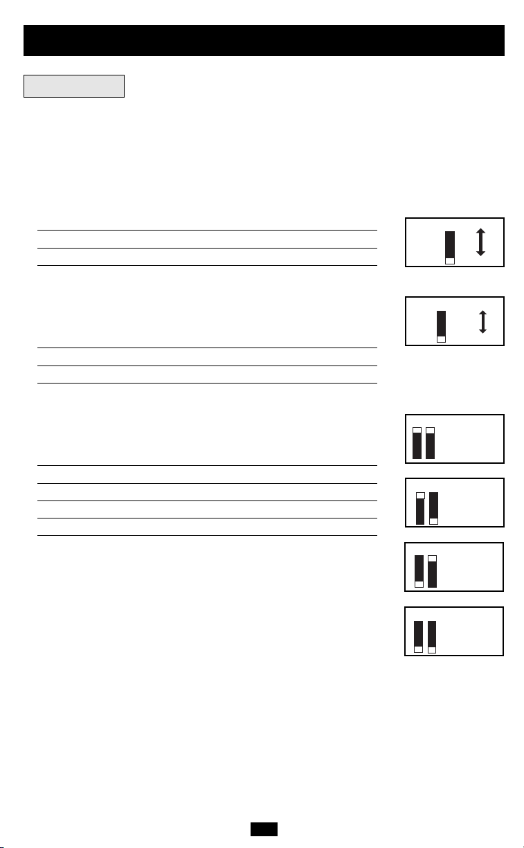
Configuration
4321
Gel Cell
Wet Cell*
4321
145V
135V*
4321
105V
4321
95V
4321
85V
4321
75V*
DIP Switches
Using a small tool, set the four “Battery Type / Voltage Point” Configuration DIP Switches
(located on the front panel of your APS); see Diagram 4, p. 28.
• Select Battery Type
CAUTION:The Battery Type DIP Switch setting must match the type of batteries you connect or your batteries may
be degraded or damaged over an extended period of time. See “Battery Selection,” page 6 for more information.
(DIP Switch #1)
BBaatttteerryy TTyyppee SSwwiittcchh PPoossiittiioonn
Gel Cell (Sealed) Battery Up
Wet Cell (Vented) Battery Down*
• Select High AC Voltage Switch To
Battery Point
VVoollttaaggee SSwwiittcchh PPoossiittiioonn
145V Up
135V Down*
(DIP Switch #2)
• Select Low AC Voltage Switch To
Battery Point
VVoollttaaggee SSwwiittcchh PPoossttiioonn
105V #4 Up & #3 Up
95V #4 Up & #3 Down
85V #4 Down & #3 Up
75V #4 Down & #3 Down*
Most loads will perform adequately when your APS’s High AC
Voltage Point DIP Switch #2 is set to 135V and its Low AC Voltage
Point DIP Switches #3 and #4 are set to 95V. However, if your APS
frequently switches to battery power due to momentary high/low
line voltage swings that would have little effect on equipment
operation, you may wish to adjust these settings. Your APS will
switch to battery due to voltage swings the least if the High AC
Voltage Switch to Battery Point is on its highest setting and the
Low AC Voltage Switch to Battery Point is on its lowest setting.
(DIP Switches #4 & #3)
* Factory default settings.
5
Page 6

Battery Selection
Selecting Battery Type
Select a battery or system of batteries that will provide your APS with proper DC voltage
and an adequate amp hour capacity.* Select ‘Deep-Cycle’ batteries to enjoy optimum
performance from your APS. Batteries of either Wet-Cell (vented) or Gel-Cell/Absorbed Glass
Mat (sealed) construction are ideal. 6 Volt “golf-cart,” Marine Deep-Cycle or 8D Deep-Cycle
batteries are also acceptable.**
* Even though APS models are high-efficiency converters of DC voltage, their rated output capacities are limited
by the amp-hour size of the external batteries. ** You must set Configuration DIP Switch #1, Group A (Battery
Type) to match the type of batteries you connect or your batteries may be degraded or damaged over an
extended period of time. See “Configuration,” page 5 for more information.)
Selecting Battery Amp Hour Capacity
1. Add the Wattage Ratings of your connected equipment to determine the Total Wattage
Required.*
2. Divide the Total Wattage Required (from Step 1) by the battery voltage to determine the
DC Amperes Required.
3. Multiply the DC Amperes Required (from Step 2) by the number of hours you estimate
will pass without AC power before your battery can be recharged to determine a Battery
Amp-Hours Required Rough Estimate.**
4. Compensate for inefficiency by multiplying your Battery Amp-Hour Required Rough
Estimate (from Step 3) by 1.2 to determine how many amp-hours of battery backup (from
one or several batteries) you should connect to your APS.Note that the Amp-Hour ratings
of batteries are usually given for a 20 hour discharge rate.Actual Amp-Hour capacities are
less when batteries are discharged at faster rates: batteries discharged in 55 minutes
provide only about 50% of their listed Amp-Hour ratings, while batteries discharged in 9
minutes provide as little as 30% of their Amp-Hour ratings.
* The wattage rating is usually stated in the equipment’s manuals or on their nameplates. If your equipment is rated in
amperes, convert to watts by multiplying the ampere rating by your nominal AC line voltage (120). ** Your charging
amps multiplied by the charging hours must exceed the discharge amp-hours taken from the batteries between charges or
you will eventually run down your battery bank.
6
Page 7
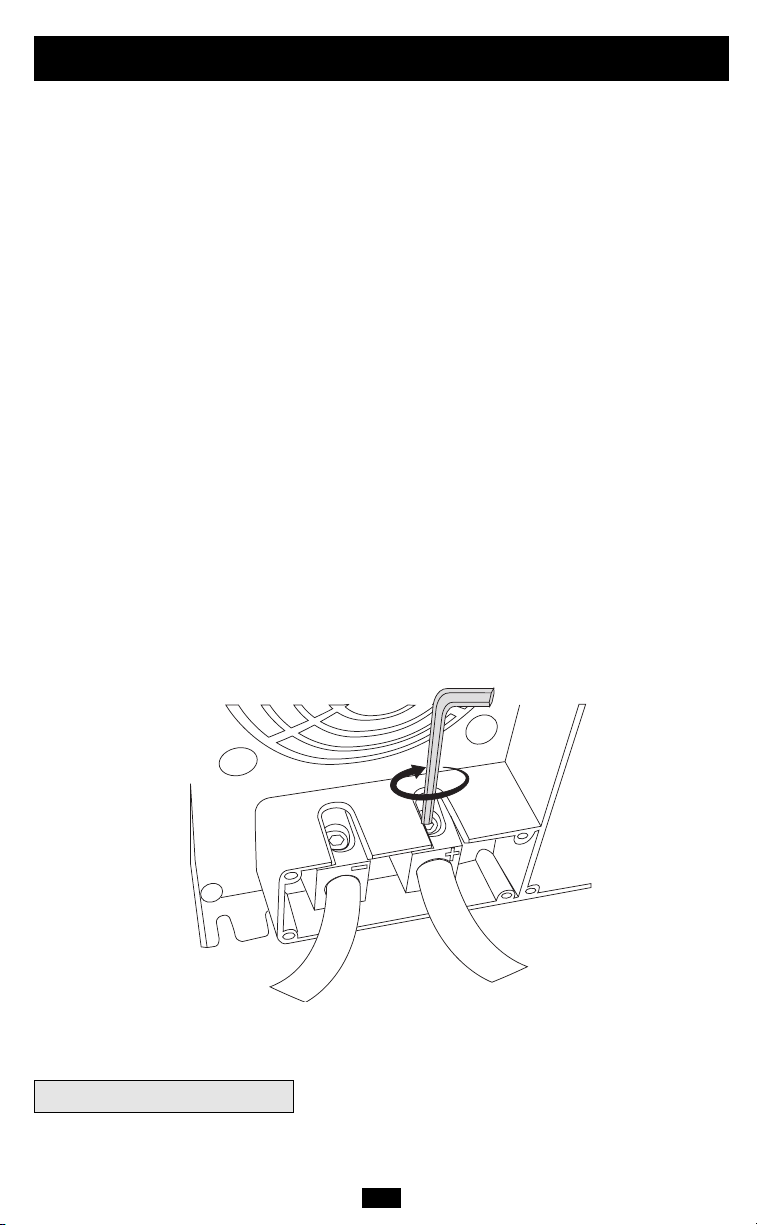
Battery Connection
1. Make sure that your APS batteries have proper overcurrent protection.
NEC article 551 requires that you install a recognized UL component fuse block and UL
listed fuse within 18 inches of the battery. The fuse’s rating must equal or exceed the
Minimum DC Fuse Rating listed in your APS model’s specifications on page 13.
2. Choose a battery configuration appropriate to your batteries.
• Single Battery Connection:Refer to Diagram 1,page 27.When using a single battery,
its voltage must be equal to the voltage of your APS's Inverter Nominal Input Voltage
(see specs).
• Parallel Battery Connection: Refer to Diagram 2, page 27. When using multiple
batteries in parallel, each battery's voltage must be equal to the voltage of your APS’s
Inverter Nominal Input Voltage (see specs).
• Series Battery Connection: Refer to Diagram 3, page 27. When using multiple
batteries in series, all batteries must be equal in voltage and amp hour capacity, and
the sum of their voltages must be equal to the voltage of your APS's Inverter Nominal
Input Voltage (see specs).
3. Securely fasten the APS’s DC connector to the battery connection cables.
For best results, use 1/0 gauge cable for battery connection. Battery connection cable
lengths should be as short as possible,and never greater than 20 feet.Using longer cables,
or cables of too small a gauge, could result in dangerous overheating or fire.*
You must tighten your battery terminals to approximately 4 Newton-meters (36 Inch
Pounds) of torque to create an efficient connection and prevent excessive heating.
Insufficiently tightening terminals could void your PowerVerter's warranty.
* APS models are capable of delivering a much higher wattage output for brief periods of time.Wiring should be
configured to handle this brief high-current draw.Though your APS is a high-efficiency converter of DC voltage,
its rated output capacity is limited by the length and gauge of the wires running from the battery to the APS.
DC Ground Connection
APS systems must be connected to a grounded,permanent wiring system. For most installations,
the negative battery conductor must be bonded to the grounding system at one (and only one)
point in the system.All installations must comply with national and local codes and ordinances.
7
Page 8

AC Connection
Before AC connection, match the power requirements of your
equipment with the power output of your APS to avoid overload.
When figuring the power requirements of your equipment, do not confuse “continuous”
power ratings with “peak” power ratings. Electric motors require more power to turn on
(“peak power”) than they require to run continuously.“Peak”power ratings are usually 2 to
5 times “continuous” ratings. Most electric motors require “peak power” only when they are
first turned on. The electric motors in equipment such as refrigerators and sump pumps,
however, constantly turn on and off according to demand. These motors require “peak
power”at multiple, unpredictable times during their operation.
You must use 15A branch circuit protection (user-supplied) on the input circuit.
AC Input Electrical Connection
Plug the line cord into an outlet providing 120V AC,60 Hz. power.Make sure that the circuit
you connect your APS to has adequate overload protection,such as a circuit breaker or a fuse.
AC Output Electrical Connection
Simply plug your equipment into the unit’s AC receptacles.
Set Operating Mode Switch
••
Switch to “AUTO/REMOTE” when you are using your connected equipment.ADVANTAGE:APS will automatically switch from providing connected equipment with utility
power to providing connected equipment with power inverted from external
batteries when utility power is unavailable.
Note: when the switch is in the "AUTO/REMOTE" position, you can remotely monitor and control your APS by
connecting a Tripp Lite Remote Control Module (sold separately) to the APS's RJ45 Remote Module Connector.
••
Switch to “CHARGE ONLY” when you are not using your connected equipment.
(WARNING! APS will not provide battery backup!) ADVANTAGES:A) Continues to
charge battery when power is present, and B) Turns OFF the APS’s inverter,
preventing battery drain during blackouts or brownouts.
• Switch to “OFF”to completely turn off the APS and connected equipment or to reset
the APS after it has shut down due to overload or overheating.
8
Page 9

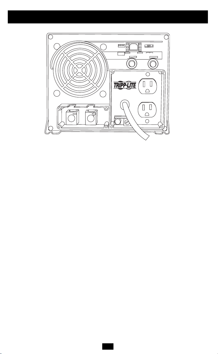
Switches, Indicator Lights & Other Features
(See Diagram 4, p. 28, to locate the following switches, indicator lights and other features.)
Switches
11.. OOppeerraattiinngg MMooddee SSwwiittcchh::
“AUTO/REMOTE”,“OFF” or “CHARGE ONLY”). See “Set Operating Mode Switch”, p. 8 to
select the appropriate setting for this switch.
This switch selects the APS operating mode (either
22.. ““CCOONNFFIIGGUURRAATTIIOONN SSWWIITTCCHHEESS””——DDIIPP SSwwiittcchheess::
These four switches must be set for the
type of battery your APS will be connected to and the voltage points at which your APS
will switch to battery power. See “Configuration”, p. 5 to select the optimum settings for
these switches.
Indicator Lights
33.. ““LLIINNEE””::
receiving utility-supplied AC power and your APS is set to “AUTO/REMOTE”,meaning that
it will automatically switch to battery power if AC power becomes unavailable. It will
flash intermittently when connected equipment is receiving utility power and your APS’s
Operating Mode Switch is set to “CHARGE ONLY” to indicate that the APS’s inverter is
OFF and that the APS will not supply power from its batteries.
44.. ““IINNVV””::
receiving battery-supplied AC power. It will flash if the APS does not detect the minimum
load necessary to activate the inverter.
55.. ““LLOOAADD””::
continuously ON when the APS’s load is between 80% and 110% of capacity, to alert you
that the inverter might not be able to support the load.The light will flash intermittently
after the APS’s inverter shuts down due to a severe overload or overheating. If this happens, turn Operating Mode Switch OFF. Remove the overload and let the unit cool.You
may then turn the APS ON after it cools.
66.. ““BBAATTTTEERRYY HHII//MMEEDD//LLOO””::
the approximate charge level and voltage of your connected battery bank and alert you
to several fault conditions:
BATTERY CHARGE INDICATION (Approximate)
**
Approximately 1/2 second on, 1/2 second off. See Troubleshooting section.
** Approximately 1/4 second on, 1/4 second off.See Troubleshooting section.
This green light will turn continuously ON whenever connected equipment is
This yellow light will turn continuously ON whenever connected equipment is
When your UPS is receiving utility-supplied AC power, this red light will turn
These THREE lights will turn ON in several sequences to show
IInnddiiccaattoorr CChhaarrggeerr FFuunnccttiioonn BBaatttteerryy LLeevveell
((LLIINNEE OONN)) ((IINNVV OONN))
Green Float High Charge State
Green & yellow Absorption (50% Done) High/Medium Charge State
Yellow Absorption Medium Charge State
Yellow & red Bulk (50% Done) Medium/Low Charge State
Red Bulk Low Charge State
All three lights off Charger Inhibited Very Low Charge State
Flashing green Equalizing Charge N/A
Flashing red N/A Low Battery Shutdown
All three lights flash slowly* Excessive discharge;check batteries
All three lights flash quickly** Overcharge;check charger
9
Page 10

Switches, Indicator Lights & Other Features
Other Features
77.. DDCC PPoowweerr TTeerrmmiinnaallss::
“Battery Connection”, p. 7 for instructions.
These terminals should be wired to your battery terminals. See
continued
88.. AACC IInnppuutt LLiinnee CCoorrdd:: NNEEMMAA 55--1155PP ffiixxeedd::
dedicated 15 Amp AC utility outlet. DO NOT plug the cord into the APS’s AC receptacles.
99.. AACC RReecceeppttaacclleess:: NNEEMMAA 55--1155RR::
would normally be plugged into a utility outlet.
1100.. RReesseettttaabbllee CCiirrccuuiitt BBrreeaakkeerrss::
due to input or output overload.The Input (Charge) Breaker helps protect the charge
input only. The Output (Load) Breaker helps prevent output overload. If a circuit
breaker trips, wait 1 minute to allow components to cool before resetting it. If the
Output Breaker trips, remove overload by plugging in equipment with a lower total
wattage draw before resetting.
1111.. RReemmoottee MMoodduullee CCoonnnneeccttoorr::
optional remote module.See the installation instructions packed with the remote module.
1122.. MMoouunnttiinngg FFllaannggeess::
slots (located on the bottom rear of the unit) to permanently mount your APS. Mount
to a sturdy, horizontal surface using user-supplied screws.
Use mounting flanges (located on the front of unit) and mounting
These receptacles allow you to connect equipment that
These circuit breakers protect your APS against damage
The front panel has an RJ45 receptacle for use with the
This cord should be plugged into a 120V, 60 Hz,
10
Page 11

Maintenance & Service
Maintenance
Your APS model requires no maintenance but should be kept dry at all times. Periodically
check all connections both at the unit and at the battery. Clean and tighten connections as
necessary.
Service
If returning your APS to Tripp Lite,please pack the APS carefully,using the ORIGINAL PACKING
MATERIAL that came with the unit. Enclose a letter describing the symptoms of the
problem. If the APS is within the warranty period,enclose a copy of your sales receipt.
Limited Warranty
Tripp Lite warrants its products to be free from defects in materials and workmanship for a period of one year
(domestic) or 120 days (export) from the date of initial purchase. Tripp Lite’s obligation under this warranty is
limited to repairing or replacing (at its sole option) any such defective products.To obtain service under this warranty
you must obtain a Returned Material Authorization (RMA) number from Tripp Lite or an authorized Tripp Lite
service center. Products must be returned to Tripp Lite or an authorized Tripp Lite service center with transportation
charges prepaid and must be accompanied by a brief description of the problem encountered and proof of date
and place of purchase. This warranty does not apply to equipment which has been damaged by accident, negligence
or misapplication or has been altered or modified in any way. This warranty applies only to the original purchaser
who must have properly registered the product within 10 days of purchase.
EXCEPT AS PROVIDED HEREIN, TRIPP LITE MAKES NO WARRANTIES, EXPRESS OR IMPLIED, INCLUDING
WARRANTIES OF MERCHANTABILITY AND FITNESS FOR A PARTICULAR PURPOSE. Some states do not
permit limitation or exclusion of implied warranties; therefore, the aforesaid limitation(s) or exclusion(s) may not
apply to the purchaser.
EXCEPT AS PROVIDED ABOVE, IN NO EVENT WILL TRIPP LITE BE LIABLE FOR DIRECT, INDIRECT, SPECIAL,
INCIDENTAL OR CONSEQUENTIAL DAMAGES ARISING OUT OF THE USE OF THIS PRODUCT, EVEN IF
ADVISED OF THE POSSIBILITY OF SUCH DAMAGE. Specifically, Tripp Lite is not liable for any costs, such as
lost profits or revenue, loss of equipment, loss of use of equipment, loss of software, loss of data, costs of
substitutes, claims by third parties, or otherwise.
Tripp Lite has a policy of continuous improvement. Specifications are subject to change without notice.
11
Page 12

Troubleshooting
Try these remedies for common APS problems before calling for help. Call Tripp Lite Customer Service at
(773) 869-1234 before returning your APS for service.
SYMPTOM PROBLEMS CORRECTIONS
APS does not provide APS not properly connected to Connect APS to utility power.
AC output (AC input present) utility power.
Circuit breaker is tripped. Reset circuit breaker.
APS shutdown due to excessive Turn APS “OFF”. Wait 1 minute and
battery voltage, indicating possible switch to “AUTO/REMOTE”.
charger failure. Line disconnected
to prevent permanent battery
damage.
APS is overheated. Check air circulation near vents.
APS is set to “OFF” Set APS to “AUTO/REMOTE” or
APS does not provide Operating Mode Switch is set Set Operating Mode Switch to “AUTO/
AC output (AC input absent) to “CHARGE ONLY”. REMOTE.”
Load or High Temperature fault. Turn APS “OFF”. Wait 1 minute.
Excessive battery discharge. Check battery condition.
APS will not charge the Connected batteries are dead. Check and replace old batteries.
battery (AC input present) (All Battery Indicator lights will be
flashing slowly.)
Battery fuse* is blown. Check and replace fuse.
Battery cabling* is loose or degraded. Check and tighten or replace cabling.
APS charger failure. Turn APS “OFF”.Wait 1 minute and
All APS Indicator Lights are This is normal if the APS is set —
OFF (AC input absent) to “CHARGE-ONLY”
All APS Indicator Lights are Excessive battery discharge. Use an auxiliary charger* to raise
OFF (AC input is present or battery voltage. Check external battery
absent) connections and fuse. Automatically
All APS Battery Indicator Excessive battery discharge. Use an auxiliary charger* to raise
Lights are slowly flashing. battery voltage. Automatically resets
APS “LOAD” Battery Light Inverter shutdown because load Turn APS “OFF”. Wait 1 minute.
flashing is too high or temperature is too Remove overload. Check that vents
high. are clear for air circulation. Switch
All APS Battery Lights are High battery voltage shutdown Check all charging sources. Reset by
rapidly flashing during battery charging. cycling control switch to "OFF" then to
APS red “BATTERY HI/MED/LO” Inverter shutting down due to low Prepare for loss of power to
light is flashing battery charge. connected equipment.
*User supplied
“CHARGE-ONLY”.
Remove overload. Check that vents
are clear for air circulation. Switch
to
“AUTO/REMOTE”.
switch to “AUTO/REMOTE”. If
automatic shutdown occurs, call
Tripp Lite Customer Service.
resets when condition is cleared.
when condition is cleared.
to
“AUTO/REMOTE”.
“AUTO/REMOTE” or “CHARGE-ONLY”.
12
Page 13

Specifications
MODEL: APS612
SERIES: AGAP60012MVJ
Weight: 38.0 lbs.
INVERTER
Continuous power (@ 20° C): 600 W
Surge power: 1200 W
Efficiency (Full Load): 90%
Minimum/Maximum DC Fuse Rating: 100A/200A
DC Input Current @ Nominal V DC
Full Load 56 A
Nominal Input Volts: 12 VDC
DC Input Voltage Range: 10-15 VDC
Nominal Output Volts: 120 VAC ±5%
Nominal Output Frequency: 60 Hz ±.3%
BATTERY CHARGER
Charging Capacity DC: 20A
Maximum Cable Length 20 ft.
Absorption Volts VDC: Selectable
Float Volts VDC (wet/gel): 13.3 V (13.6 V)
Input Voltage AC: 120 V
Input Current AC: 4.2 A
LINE VAC OPERATION
Minimum Input AC Volts: Selectable 75*,85, 95, or 105 VAC
Maximum Input AC Volts
(Continuous, Charger at Maximum): Selectable 135* or 145 VAC
Maximum Input Current
(Continuous, Charger at Maximum): 9.5 A
Input Frequency: 60 Hz ±3%
Maximum Output AC (Continuous) 5 A
Automatic Transfer Time: <25 ms
* Factory default setting.
14.4 V*/14.2 V Wet*/Gel
Note on Labelling
Two symbols are used on the APS labels.
: AC Voltage
V~
V
: DC Voltage
13
Page 14

Manual de Operación
APS 612 PowerVerter
Inversores / Cargadores de Energía (120V, 60 Hz)
• Con Voltaje y Frecuencia Controlada • Energía de Cresta • Alta Eficiencia
Introducción
Seguridad
Configuración y Conexión
Características
Mantenimiento y Servicio
Garantía
®
15
17
18
22
24
24
Resolución de Problemas
Especificaciones
English
1111 W. 35th Street Chicago, IL 60609 USA
Servicios a Clientes: (773) 869-1234 • www.tripplite.com
Copyright © 2002 Tripp Lite. Propiedad Literaria de Tripp Lite 2002. Reservados todos los derechos.
141414
25
26
1
Page 15

Introducción
¡Felicitaciones! Usted ha adquirido el inversor / cargador de batería integrado más
avanzado y con más características en el mercado. Este modelo APS suministrará a sus
equipos energía de CA mientras ésta esté presente. Durante un apagón, caída o subida de
voltaje,esta unidad cambia automáticamente a la batería externa para suministrar energía de
CA de voltaje y frecuencia controlada.
Salida de Alta Eficiencia
La circuitería avanzada de este sistema APS produce una conversión de alta eficiencia de
CD a CA, minimizando así la pérdida de energía. Esto le permite a usted operar los equipos
conectados por períodos prolongados entre carga y carga de las baterías. Este sistema
mantendrá la salida de alta eficiencia aún mientras disminuye la carga de las baterías.
Protección Automática contra Sobrecargas
Si usted sobrecarga este APS, la unidad protegerá automáticamente sus baterías y a sí
misma contra daños.
Luces Indicadoras de Funciones Múltiples
Varios juegos de luces indicadoras de funciones múltiples le mantienen constantemente
informado acerca de los niveles de carga de la batería,fallas y operación del sistema APS.
Interruptores de Operaciones Múltiples
Una variedad de interruptores ajustables por el usuario le ofrecen convenientes opciones
para operar el sistema APS. Usted puede seleccionar el nivel de voltaje de activación del
inversor del APS para maximizar la protección de sus equipos y minimizar el desgaste de
las baterías; regular el APS para incrementar la eficiencia de recarga de acuerdo al tipo de
baterías utilizadas; y hasta activar la operación de su APS por control remoto.
15
Page 16

Introducción
15
14
13
12
Etapa 2
Absorción
Etapa 3
Allmentación
por Flotador
Estapa 1 Alimentación en Mass
VOLTAJE DE BATERÍA
TIEMPO
Perfil de Carga
continua
Cargador Avanzado
de 3 Etapas para Baterías
Este sistema APS recargará sus baterías más
rápido que otros cargadores convencionales
debido a que su perfil de recarga de 3 etapas
(Alimentación en Masa, Absorción y
Alimentación por Flotador) provee óptimo
rendimiento independientemente del tipo de
baterías que usted utilice (Húmeda o de Gel).*
Además, el sistema avanzado de recarga
protege contra exceso de carga y descarga
para prolongar la vida útil de sus baterías.
* Los niveles de Absorción y Alimentación por Flotador
varían de acuerdo al tipo de baterías conectadas. Esta
unidad puede ser regulada para operar con Baterías
Húmedas o de Gel.
Inversor con Salida de
Frecuencia Controlada
Todos los modelos APS incluyen Inversores
con Salida de Frecuencia Controlada para
permitir que los equipos que dependen de la
frecuencia de la línea de CA (como c
omputadoras, grabadoras de video, lectores de
CD, grabadoras de audio, relojes eléctricos y
tocadiscos) operen correctamente.
Tarjetas de Circuitos Protegidas
Tarjetas de circuitos son protegidas por
revestimiento de conformación de silicona
transparente.
16
Page 17

Seguridad
GUARDE ESTAS INSTRUCCIONES
EEssttee mmaannuuaall ccoonnttiieennee aaddvveerrtteenncciiaass ee iinnssttrruucccciioonneess iimmppoorrttaanntteess qquuee ddeebbeenn sseegguuiirrssee dduurraannttee
llaa iinnssttaallaacciióónn,, ooppeerraacciióónn yy aallmmaacceennaajjee ddee ttooddooss llooss SSiisstteemmaass AAPPSS ddee TTrriipppp LLiittee..
Precauciones Sobre la Ubicación del APS
• Instale este sistema bajo techo, lejos de calor o humedad excesivos,polvo o luz solar directa.
• Deje suficiente espacio alrededor del APS para permitir ventilación adecuada.
• No instale este sistema APS cerca de dispositivos magnéticos de memoria ya que esto
puede producir la corrupción de los datos grabados.
• Los modelos APS no son impermeables o resistentes al agua. El contacto con agua
puede causar cortocircuitos y lesiones corporales debido a choques eléctricos. No
sumerja este APS. Instálelo en el lugar más seco posible.
Precauciones Sobre la Conexión de Baterías
• El APS no funcionará, con alimentación de la red o sin ella, hasta que se conecten las pilas.
• Los sistemas múltiples de baterías deben estar formados por baterías del mismo tipo,
voltaje, edad y capacidad en amperios/hora.
• Mantenga ventilación adecuada. Gases hidrógenos explosivos pueden acumularse
cerca de las baterías si el área no está bien ventilada.
• Durante la conexión final de las baterias pueden producirse chispas.
• No permita que ningún objeto foráneo entre en contacto con las terminales de
entrada de CD.No conecte estas terminales entre sí con ningún objeto. Esto puede
producir serias lesiones corporales o daños a objetos.
Precauciones Sobre la Conexión de Equipos
• No utilice los Sistemas APS de Tripp Lite en aplicaciones para el soporte de la vida
humana donde una falla del APS pueda causar anomalías o alterar significativamente
el rendimiento del dispositivo de soporte de vida.
• No conecte supresores de sobretensiones transitorias, reguladores de voltaje,
acondicionadores de línea o no-breaks / sistemas UPS a los receptáculos de salida de
esta unidad.
• No modifique el enchufe del APS de forma tal que se elimine la conexión a tierra.No
use adaptadores de potencia que eliminen la conexión a tierra del enchufe.Conecte el
APS exclusivamente a tomas de corriente alterna debidamente conectadas a tierra. No
conecte el APS a sí mismo; con ello se dañaría el APS y quedaría sin efecto la garantía.
Precauciones de Operación
• Este sistema APS no requiere mantenimiento rutinario alguno. No abra este sistema APS
por ninguna razón. No existen partes interiores que puedan ser reparadas por el usuario.
• Existen voltajes potencialmente letales dentro de esta unidad mientras las baterías
estén conectadas. Durante cualquier procedimiento de servicio, siempre deben
desconectarse las baterías y la entrada de CA (cuando sea necesario).
• No conecte o desconecte baterías mientras el sistema APS esté operando con la
energía de las baterías.
17
Page 18

Configuración
4321
Bateria
de Gel
Bateria*
Húmeda
4321
145V
135V*
4321
105V
4321
95V
4321
85V
4321
75V*
Interruptores DIP
Usando una herramienta pequeña, ajuste los 4 Interruptores DIP de Configuración, Grupo
A: “Battery Type / Voltage Point” (tipo de baterías / punto de voltaje) ubicados en el panel
frontal del sistema APS (vea el Diagrama 4, página 28) para seleccionar el tipo de baterías
que desea utilizar y programar el rango de voltaje para el cambio automático del sistema APS a
energía de batería.
• Seleccione el Tipo de Baterías (Interruptor DIP No. 1)
PRECAUCION: El Interruptor DIP “Battery Type”(tipo de baterías), para seleccionar el tipo de baterías, debe
ser colocado en la posición correcta y de acuerdo al tipo de baterías utilizadas para evitar daños o desgaste
durante un período extendido de tiempo.Refiérase a la sección “Selección de Baterías” en la página 19 para
obtener más información.
TTiippoo ddee BBaatteerrííaa PPoossiicciióónn ddeell IInntteerrrruuppttoorr
Batería de Gel (Sellada) Arriba
Batería Húmeda (Ventilada) Abajo*
• Seleccione el Punto Alto de Voltaje de CA
para el Cambio a Batería
VVoollttaajjee PPoossiicciióónn ddeell IInntteerrrruuppttoorr
145V Arriba
135V Abajo*
• Seleccione el Punto Bajo de Voltaje de CA
para el Cambio a Batería
VVoollttaajjee PPoossiicciióónn ddeell IInntteerrrruuppttoorr
105V #4 Arriba & #3 Arriba
95V #4 Arriba & #3 Abajo
85V #4 Abajo & #3 Arriba
75V #4 Abajo & #3 Abajo*
(
Interruptor DIP No. 2)
(Interruptores DIP No. 4 y No. 3)
La mayoría de las cargas funcionarán correctamente cuando el
Interruptor DIP No. 2 para el ajuste del Punto Alto de Voltaje de CA
está regulado a 135 V y los Interruptores DIP No. 3 y No. 4 para el
ajuste del Punto Bajo de Voltaje de CA están regulados a 95 V. No
obstante,si su sistema APS cambia frecuentemente a batería debido
a las fluctuaciones de alto / bajo voltaje que no interfieren con la
operación de sus equipos, usted pude cambiar estos ajustes.
Incrementando el Punto Alto de Voltaje de CA para el Cambio a
Batería y/o disminuyendo el Punto Bajo de Voltaje de CA para el
Cambio a Batería, usted puede reducir el número de veces que su
sistema APS cambia a batería debido a fluctuaciones de voltaje.
* Regulación de fábrica
18
Page 19

Selección de Baterías
Seleccione el Tipo de Batería(s)
Seleccione una batería o sistema de baterías que suministre voltaje apropiado de CD y
capacidad adecuada en amperios / hora al sistema APS.* Seleccione baterías de ciclo
profundo para obtener el máximo rendimiento de su sistema APS. Las baterías húmedas
(ventiladas) o de gel / fibra de vidrio absorbido (selladas) son ideales. Las baterías de 6
voltios (“golf-cart”), ciclo profundo marino o ciclo profundo 8D también son aceptables.**
* Aún cuando los sistemas APS son inversores de energía de alta eficiencia, su capacidad de salida será
limitada por el tamaño en amperios/hora de sus baterías externas. ** Usted debe ajustar el Interruptor DIP
No. 1, Grupo A (tipo de batería) de acuerdo con el tipo de baterías que desea conectar.De lo contrario, las
baterías pueden sufrir daños o desgaste excesivo durante un prolongado periodo de tiempo. Refiérase a la
sección “Configuarción” en la página 18 para obtener más información.
Seleccione la Capacidad en Amperios/Hora de las Baterías
1. Sume los índices de demanda eléctrica de los equipos que desea conectar para
determinar el Total Requerido en Vatios.*
2. Divida el Total Requerido en Vatios (obtenido en el paso 1) entre el voltaje de entrada del
sistema APS para determinar el Indice de Amperios de CD Requerido.
3. Multiplique el Indice de Amperios de CD Requerido (obtenido en el paso 2) por el
número de horas (estimado) que pasará sin energía de CA antes de que las baterías puedan
recargarse, para determinar un Estimado Aproximado de Capacidad en Amperios-Hora.**
4. La capacidad de baterías en Amperios/Hora se indica usualmente para una intensidad de
descarga de 20 horas. La capacidad actual en Amperios/Hora es menor cuando la batería
se descarga a mayor intensidad. Compense por la ineficacia multiplicando el Estimado
Aproximado en Amperios-Hora de su Batería (obtenido en el Paso 3) por 1.2 para
determinar cuantos amperios-hora de respaldo de batería (suministrados por una o varias
baterías) debe conectar al APS.Tenga en cuenta que las capacidades en Amperios-Hora de las
baterías usualmente se expresan para un índice de descarga de 20 horas. Las capacidades
verdaderas en Amperios-Hora disminuyen cuando las baterías se descargan a mayor
velocidad: las baterías que se descargan en 55 minutos proporcionan solamente un 50%
de la capacidad nominal, mientras que las baterías que se descargan en 9 minutos
proporcionan solamente 30% de su capacidad nominal en Amperios-Hora.
* La demanda eléctrica de los equipos electrónicos normalmente se encuentra en el manual de operación o
en la placa de identificación. Si este índice está expresado en amperios, conviértalos a vatios multiplicando
los amperios por el voltaje nominal de línea (120). ** El resultado de la multiplicación de los amperios de
carga y las horas de carga debe exceder los amperios/hora de descarga tomados de las baterías entre carga
y carga. De lo contrario, eventualmente se desgastará totalmente su banco de baterías.
19
Page 20

Conexión de Baterías
1. Confirme que las baterías del APS cuenten con adecuada protección para sobrecargas
de corriente.
El artículo NEC 551 requiere que usted instale un bloque de fusibles de componente UL
reconocido y un fusible UL listado a 18 pulgadas de la batería. La capacidad en amperios
del fusible debe ser igual o superior a la capacidad mínima de amperios de CC del fusible
que se muestra en la ficha técnica del modelo del APS en la página 26.
2. Elija una configuración de batería apropiada para las baterías.
• Conexión de una sola batería:Refiérase al Diagrama 1,página 27.Cuando se use
una sola batería, el voltaje deberá ser igual al voltaje nominal de entrada del
inversor del APS (refiérase a la ficha técnica).
• Conexión de la batería paralela: Refiérase al Diagrama 2, página 27. Cuando se
use baterías múltiples en paralelo, el voltaje de cada batería deberá ser igual al
voltaje del voltaje nominal de entrada del inversor del APS (refiérase a la ficha
técnica).
• Conexión de baterías en serie:Refiérase al Diagrama 3,página 27. Cuando se use
baterías múltiples en serie, todas la baterías deben ser iguales en voltaje y
capacidad en amperios hora, y la suma de los voltajes deberá ser igual al
voltaje del voltaje nominal del inversor del APS (refiérase a la ficha técnica).
3.Ajuste adecuadamente el conector de CC del APS a los cables de conexión de la batería.
Para mejores resultados,use un cable de calibre 1/0 AWG para la conexión de la batería.
Las longitudes de los cables de batería deben ser tan cortas como sea posible, y jamás
deben ser mayores que 6 metros.El uso de cables más largos, o cables de un calibre más
pequeño, puede provocar un peligroso sobrecalentamiento o fuego.*
Debe ajustar los terminales de su batería aproximadamente con un torque de 4
Newton-metros (36 libras-pulgada) para crear una conexión eficaz y evitar el excesivo
calentamiento. Un ajuste insuficiente de los terminales podría anular la garantía de su
PowerVerter.
* Los modelos del APS tienen la capacidad de producir un vataje de salida mucho más alto por breves periodos
de tiempo. El cableado debe configurarse para manejar estos breves episodios de corriente alta.A pesar de que el
APS es un conversor de electricidad de alta eficacia, la capacidad nominal de salida está limitada por la longitud y medida de los cables que van desde la batería hasta el APS.
Conexión de CD a Tierra
Los sistemas APS deben conectarse a una instalación eléctrica permanente y con conexión a
tierra. En la mayoría de las instalaciones, el conductor negro de la batería debe estar
soldado al sistema de conexión a tierra en un punto (y solamente uno) del sistema.Todas
las instalaciones deben cumplir con los códigos y regulaciones nacionales y locales.
20
Page 21

Conexión de CA
Antes de la conexión de CA, cerciórese de que la demanda
de energía de sus equipos coincida con la capacidad de salida
del APS para evitar sobrecargas.
Cuando calcule la demanda de energía de sus equipos, no confunda el índice de energía
“continua” con el índice de energía “de cresta”. Ciertos motores eléctricos necesitan más
energía para arrancar (“energía de cresta”) de lo que requieren para su operación continua.
Los índices de energía “de cresta”son normalmente de 2 a 5 veces mayores que los índices
de energía “continua”. La mayoría de los motores eléctricos demandan “energía de cresta”
solamente para su arranque. No obstante, otros motores eléctricos, como los incluidos con
refrigeradores y bombas de agua, se encienden y se apagan continuamente de acuerdo con
la demanda impuesta. Estos motores pueden requerir “energía de cresta” a intervalos
múltiples e imprevisibles durante su operación.
Usted debe utilizar la protección del circuito de rama 15A (proporcionado por el usuario)
en el circuito de entrada.
Conexión de la Entrada Eléctrica de CA
Enchufe el cable a una toma que suministre energía de 120V de CA y 60 Hz.Cerciórese de
que el circuito al cual desea conectar el sistema APS posea protección adecuada contra
sobrecargas, como un interruptor de circuitos o un fusible.
Conexión de la Salida Eléctrica de CA
Simplemente conecte sus equipos a los receptáculos de CA de la unidad.
Regule el Interruptor “Operating Mode”
• Colóquelo en la posición “AUTO/REMOTE”(automático / remoto) cuando usted desee
utilizar los equipos conectados.VENTAJA:Suministra energía de respaldo durante caídas
de voltaje y apagones.
Nota: cuando el conmutador está en la posición "AUTO/REMOTE", puede vigilar y controlar su APS
conectando un Módulo de control remoto de Tripp Lite (vendido por separado) al conector RJ45 del módulo
remoto del APS.
• Colóquelo en la posición “CHARGE ONLY”(recarga solamente) cuando usted no
necesite utilizar los equipos conectados. (¡ADVERTENCIA! el sistema APS no
suministrará energía de respaldo) VENTAJAS:A) Continúa recargando las baterías
cuando la energía eléctrica está presente, y B) Apaga el Inversor del sistema APS para
prevenir el desgaste de las baterías durante apagones y caídas de voltaje.
• Colóquelo en la posición “OFF” (apagado) para apagar completamente el APS y los
equipos conectados o para restablecer el sistema APS después de que éste se haya
apagado debido a una sobrecarga o calor excesivo.
21
(Modo de Operación)
Page 22

Interruptores, Luces Indicadoras y
Otras Características
(Vea el Díagrama 4 en la página 28 para localizar los siguientes interruptores, luces indicadoras y
otras características.)
Interruptores
11.. IInntteerrrruuppttoorr ““OOppeerraattiinngg MMooddee”” ((MMooddoo ddee ooppeerraacciióónn))::
de operación del sistema APS: “AUTO/REMOTE” (automático/remoto);“OFF” (apagado);
“CHARGE ONLY” (recarga solamente). Vea la sección “Conexión de CA” en p. 21 para
seleccionar la regulación más favorable de este interruptor.
Este interruptor selecciona el modo
22.. IInntteerrrruuppttoorreess ddee CCoonnffiigguurraacciióónn ((““CCoonnffiigguurraattiioonn SSwwiittcchheess””)) –– IInntteerrrruuppttoorreess DDIIPP))::
cuatro interruptores deben ser regulados de acuerdo al tipo de baterías conectadas al
sistema APS y los puntos de voltaje en que el sistema APS suministrará energía de batería.
Refiérase a la sección “Configuración”en la página 18 para seleccionar la regulación más
favorable de estos interruptores.
Luces Indicadoras
33.. ““LLIINNEE”” ((LLíínneeaa))::
conectado esté recibiendo energía de CA suministrada comercialmente y su APS esté
configurado como "AUTO/REMOTE", lo que significa que automáticamente se cambiará a
energía de la batería si la energía de CA no está disponible. Parpadeará en forma intermitente cuado el equipo conectado reciba energía suministrada comercialmente y el
Interruptor del modo de funcionamiento de su APS esté configurado como "CHARGE
ONLY",para indicar que el inversor de APS está APAGADO y que el APS no suministrará
energía de sus baterías.
44.. ““IINNVV”” ((IInnvveerrssoorr))::
conectado esté recibiendo energía de CA suministrada por una batería. Parpadeará si el
APS no detecta la carga mínima necesaria para activar el inversor.
55.. ““LLOOAADD”” ((CCaarrggaa CCoonneeccttaaddaa))::
comercialmente, esta luz roja se encenderá de forma continua cuando la carga de AP se
encuentre entre el 80% y el 100% de capacidad, para advertirle de que el inversor no
podrá soportar la carga. La luz parpadeará de forma intermitente después de que el
inversor de APS se apague como consecuencia de una sobrecarga o sobrecalentamiento
severos. Si esto sucede,APAGUE el interruptor de modo de operación. Retire la sobrecarga
y deje que la unidad se enfríe. Puede ENCENDER el APS después que se haya enfriado.
Esta luz verde estará encendida continuamente siempre que el equipo
Esta luz amarilla se encenderá continuamente cuando el equipo
Cuando su UPS recibe energía de CA suministrada
Estos
22
Page 23

Interruptores, Luces Indicadoras y
Otras Características
66.. ““BBAATTTTEERRYY HHII//MMEEDD//LLOO”” ((BBAATTEERRÍÍAA HHII//MMEEDD//LLOO))::
secuencias para mostrar el nivel de carga y el voltaje aproximados del banco de baterías
conectado y advertirle sobre varias fallas:
INDICACIÓN DE LA CARGA DE LA BATERÍA (Aproximado)
IInnddiiccaaddoorr FFuunncciióónn ddeell ccaarrggaaddoorr NNiivveell ddee llaa bbaatteerrííaa
Verde Flotar Estado de carga alta
Verde y amarillo Absorción (50% listo) Estado de carga alta/media
Amarillo Absorción Estado de carga media
Amarillo y rojo Volumen (50% listo) Estado de carga media/baja
Red Bulk Estado de carga baja
Rojo Volumen Estado de carga muy baja
Parpadeo verde Igualando carga N/D
Parpadeo rojo N/D Apagado por batería baja
Las tres luces parpadean lentamente* Descarga excesiva,revisar baterías
* Aproximadamente 1/2 segundo encendida, 1/2 segundo apagada.Refiérase a la sección Solución de problemas.
**Aproximadamente 1/4 de segundo encendida, 1/4 de segundo apagada. Puede indicar la existencia de una
falla del cargador de batería.Refiérase a la sección Solución de problemas.
7.
88.. CCaabbllee ddee LLíínneeaa ddee CCAA:: NNEEMMAA 55--1155PP ffiijjoo::
99.. RReecceeppttááccuullooss ddee CCAA:: NNEEMMAA 55--1155RR ::
1100.. IInntteerrrruuppttoorreess aauuttoommááttiiccooss rreessttaauurraabblleess::
1111.. CCoonneeccttoorr ppaarraa eell MMóódduulloo ddee CCoonnttrrooll RReemmoottoo::
Las tres luces parpadean rápidamente** Sobrecarga.Revisar cargador
Otras Características
TTeerrmmiinnaalleess ddee EEnnttrraaddaa ddee CCDD ::
batería externa o sistema externo de baterías. Sus baterías o sistema de baterías deben
proporcionar voltaje adecuado de CD al sistema APS y a sus equipos, y también
capacidad adecuada en amperios/hora. Refiérase a la sección “Selección de Baterías”en
la página 19 para obtener más información.
CA dedicado de 15 amperios y 120V,60 Hz. NO CONECTE este cable a los receptáculos
de CA del sistema APS.
equipos diseñados para operar a 120V de CA y 60 Hz.
APS contra daños debidos a sobrecargas en la entrada o la salida. El interruptor de
entrada (carga de batería) ayuda a proteger solamente la entrada de la carga de batería.
El interruptor de salida (carga de consumo) ayuda a evitar una sobrecarga en la salida.
Si se dispara un interruptor automático, espere 1 minuto para permitir que los
componentes se enfríen antes de restablecerlo. Si se dispara el interruptor de salida,
elimine la sobrecarga conectando mediante la conexión de equipo con un consumo total
menor, antes de restablecer el interruptor.
incluye un conector tipo RJ45 para utilizarlo con el módulo opcional de control
remoto. (Este módulo se incluye con los modelos “VR”). Refiérase a las instrucciones
incluidas con el módulo de control remoto.
continua
Estas tres luces se encenderán en varias
((LLÍÍNNEEAA EENNCCEENNDDIIDDAA)) ((IINNVV EENNCCEENNDDIIDDOO))
Las tuercas aseguran los cables provenientes de la
Este cable debe conectarse a un enchufe de
Estos receptáculos permiten la conexión de
Estos interruptores automáticos protegen su
El panel frontal de todos los modelos
1122.. BBrriiddaass ddee mmoonnttaajjee::
ranuras de montaje (ubicadas en la parte posterior inferior de la unidad) para montar
su APS en forma permanente. Realice el montaje en una superficie horizontal robusta
usando tornillos suministrados por el usuario.
Use las bridas (ubicadas en la parte frontal de la unidad) y las
23
Page 24

Mantenimiento y Servicio
Mantenimiento
Este sistema APS no requiere mantenimiento alguno.No obstante, debe mantenerse seco en
todo momento.Verifique periódicamente todas las conexiones y cables en la unidad y sus
baterías. Apriete y limpie estas conexiones como sea necesario.
Servicio
Si necesita enviar el sistema APS a Tripp Lite,por favor empáquelo cuidadosamente usando
el MATERIAL ORIGINAL DE EMPAQUE.Adjunte una carta con la descripción de los síntomas
del problema.Si la unidad está dentro del período de garantía, adjunte una copia de su factura
o recibo original de compra.
Garantía Limitada
Tripp Lite garantiza que sus productos estarán libres de defectos en materiales y mano de obra por un período
de un año (unidades utilizadas en EE.UU.) ó 120 días (unidades utilizadas fuera de EE.UU) a partir de la fecha
inicial de compra. La obligación de Tripp Lite bajo esta garantía está limitada a reparar o reemplazar (a sola
discreción de Tripp Lite) los productos defectuosos. Para obtener servicio bajo esta garantía usted debe obtener un
número de Autorización de Devolución de Material (RMA) de Tripp Lite o de uno de sus centros autorizados de
servicio. Los productos defectuosos deben ser enviados, con los cargos de transporte pagados, a Tripp Lite o a
uno de sus centros autorizados de servicio y deben estar acompañados por una breve descripción del problema
que ha experimentado el usuario y comprobación de fecha y lugar de compra. Esta garantía no cubre equipos
que hayan sido dañados por accidente, negligencia o uso incorrecto, o que hayan sido alterados o modificados
en forma alguna. Esta garantía sólo es válida para el comprador original, quien debe registrar correctamente este
producto dentro de los primeros 10 días de la fecha de compra.
EXCEPTO COMO SE ESPECIFICA EN ESTE DOCUMENTO, TRIPP LITE NO EXTIENDE NINGUNA GARANTIA
EXPRESA O IMPLICITA, INCLUYENDO GARANTIAS DE COMERCIALIZACION Y APTITUD PARA UN PROPOSITO
PARTICULAR. Algunos estados no permiten limitaciones o exclusiones de garantías implícitas;por consiguiente,
es posible que la(s) limitación(es) o exclusión(es) mencionada(s) no sean aplicables al comprador.
EXCEPTO COMO SE ESPECIFICA EN ESTE DOCUMENTO, TRIPP LITE NO SERA RESPONSABLE, EN NINGUN
CASO, POR DAÑOS O PERJUICIOS DIRECTOS, INDIRECTOS, INCIDENTALES O CONSIGUIENTES QUE
SURJAN POR EL USO DE ESTE PRODUCTO, AUN SI EXISTEN ADVERTENCIAS PREVIAS SOBRE LA POSIBILIDAD DE DICHOS DAÑOS. Específicamente, Tripp Lite no es responsable por costo alguno, como
pérdidas de ganancias o réditos, pérdidas de equipos, pérdida de uso de equipos, pérdida de software, pérdida
de datos, costo de equipos sustitutos, reclamos por terceras u otras partes.
24
Page 25

Resolucion de Problemas
Si experimenta problemas comunes refiérase a esta guía antes de llamar al centro de servicios.Llame
al Servicios a Clientes de Tripp Lite antes de enviar el sistema APS.
SIMTOMA PROBLEMAS SOLUCION
El sistema APS no suministra APS no connecta correctamente Conecte el sistema APS a una toma
salida de CA (energía de CA a la toma de energía eléctrica. de energía eléctrica.
disponible)
El sistema APS no suministra El Interruptor de Circuitos está Reajuste el interruptor de circuitos.
salida de CA (energía de CA extendido.
ausente)
El sistema APS no recarga las Las baterías conectadas están Verifique y reemplace las baterías
baterías (energía de CA totalmente descargadas. usadas.
disponible)
Todas las Luces Indicadoras Esto es normal si el interruptor del —
del sistema APS están sistema APS está en la posición
apagadas (energía de CA “Charge Only” (recarga solamente).
ausente)
Todas las Luces Indicadoras Descarga excesiva de la batería. Utilice un cargador auxiliar* para
del sistema APS están incrementar el voltaje de las baterías. Verifique las conexiones de las
apagadas (energía de CA baterías externas y sus fusibles.
disponible o ausente)
Todas las Luces Indicadoras Descarga excesiva de la batería. Utilice un cargador auxiliar* para
de las condiciones de las incrementar el voltaje de las baterías.
baterías parpadean Se restablece automáticamente.
lentamente.
La Luz Indicadora “LOAD” El inversor ha sido desactivado debido Restablezca la unidad moviendo el
del sistema APS parpadea a que el voltaje de la batería es muy interruptor a la posición “OFF” y
Todas las Luces Indicadoras La batería ha sido desactivada Verifique todas las fuentes de recarga.
de las condiciones de las debido al alto voltaje durante el Restablezca moviendo el interruptor a
baterías parpadean modo de Recarga. “OFF” y luego a “AUTO/REMOTE”.
rápidamente
La Luz Indicadora “LOAD” Sobrecarga del inversor. Si esta Restablezca la unidad reduciendo la
carge (carga conectada) condición se mantiene por más de conectada y moviendo el interruptor a
parpadea rápidamente 5 segundos se apagará el inversor. “OFF” y luego a “AUTO/REMOTE” .
Interruptor de circuitos extendido. Restablezca el interruptor de circuitos.
El sistema APS ha sido desactivado Apague el sistema APS. Espere 1
debido al voltaje excesivo de la minuto y coloque el interruptor en la
batería, lo que indica una posible posición “AUTO/REMOTE” .
falla del cargador. Desconecte la
unidad de la línea de CA.
El sistema APS está apagado (OFF). Coloque el interruptor del sistema APS
El Interruptor “Operating Mode” (modo Coloque el Interruptor “Operating Mode”
de operación) está en la posición en la posición “AUTO/REMOTE”.
“Charge Only” (recarga solamente).
Indica temperatura excesiva o Apague el APS. Remueva la sobrecarga.
falla de la carga conectada. Espere1minuto.
Descarga excesiva de la batería. Verifique las condiciones de las
El fusible de la batería* se ha quemado. Verifique y reemplace el fusible.
El cableado de la batería* está Verifique y apriete o reemplace el
flojo o dañado. cableado.
Falla en el cargador del sistema APS. Apague el APS. Espere 1 minuto y
bajo por más de 5 segundos. Esta luego a la posición “AUTO/REMOTE”.
protege las baterías contra daños.
en “AUTO/REMOTE” o “CHARGE ONLY”.
Cambiea“AUTO/REMOTE.”
baterías.
coloque el interruptor en la posición
“AUTO/REMOTE”. Si se apaga
automáticamente, llame al Servicios
a Clientes de Tripp Lite.
*Suministrado por el usuario
25
Page 26

Especificaciones
MODELO: APS612
SERIO: AGAP60012MVJ
Peso: 11.9 Kg
INVERSOR
Energía continua a 20º C 600 Vatios
Energía de sobretensiones transitorias: 1200 Vatios
Eficiencia (Carga Completa): 90%
Indice Mínimo/Maximo de Capacidad del Fusible: 100A/200A
Corriente de Entrada de CD a Niveles Nominales
Carga Completa: 56 A
Voltios Nominales de Entrada: 12 V de CD
Gama de Voltaje de Entrada de CD: 10 a15 V de CD
Voltios Nominales de Salida: 120V de CA ±5%
Frecuencia Nominal de Salida: 60 Hz ±.3%
CARGADOR DE BATERIAS
Capacidad de Carga de CD: 20 A
Longitud Máxima del Cable: 20 pies
Aceptación de Voltios de CD: Programable 14.4*/14.2 V Húmeda*/Gel
Flotador - Voltios de CD (con batería de gel): 13.3 V (13.6 V)
Voltaje de Entrada de CA: 120 V
Corriente de Entrada de CA: 4.2 A
OPERACION EN LINEA DE CA
Entrada Mínima en Voltios de CA: Programable 75*, 85, 95 ó 105V de CA
Entrada Máxima en Voltios de CA:
(Continua, Cargador al Máximo) Programable 135* ó 145V de CA
Corriente Máxima de Entrada
(Continua, Cargador al Máximo) 9.5 A
Frecuencia de Entrada: 60 Hz ±3%
Salida Máxima de CA (Continua): 5 A
Tiempo de Transferencia Automática: <25 milisegundos
*Regulación de fábrica.
Nota sobre el etiquetado
Dos símbolos se utilizan en las etiquetas
del APS.
: Voltaje CA
V~
: Voltaje CD
V
26
Page 27

Diagrams/Esquemas
X/2 Volts X/2 Volts
APS
X Volts
APS
X Volts X Volts X Volts X Volts
APS
1.1
1
See Battery Connection, Pg. 7. 1.1 is the fuse.X= Your APS’s Inverter's Nominal Input Voltage. (See specs.)
Refiérase a la sección Conexión de baterías, Pág. 20. 1.1 representa el fusible.X= Voltaje nominal de entrada del inversor del
APS. (Refiérase a la ficha técnica).
2
X
See Battery Connection, Pg. 7. 2.1 is the fuse.
Refiérase a la sección Conexión de baterías, Pág. 20. 2.1 representa el fusible.X= Voltaje nominal de entrada del inversor del
APS. (Refiérase a la ficha técnica).
3
= Your APS’s Inverter’s Nominal Input Voltage. (See specs.)
3.1
2.1
X
See Battery Connection, Pg. 7. 3.1 is the fuse.
Refiérase a la sección Conexión de baterías, Pág. 20. 3.1 representa el fusible.
APS. (Refiérase a la ficha técnica).
= Your APS’s Inverter’s Nominal Input Voltage. (See specs.)
27
X
= El voltaje nominal de entrada del inversor del
Page 28

Diagrams/Esquemas
4
7
1. Operating Mode Switch
2. DIP Switches
3. “LINE”
4. “INV” (Inverting)
5. “LOAD”
6. “BATTERY HI/MED/LO”
7. DC Input Connectors
8. AC Input Line Cord
9. AC Output Terminals
10. Resettable Circuit Breakers
11. Remote Module Connector
12. Mounting Flanges
11 3 4 5
62
12
1. Interruptor “Operating Mode”
(Modo de operación)
2. Interruptores DIP
3. “LINE” (Línea)
4. “INV” (Inversor)
5. “LOAD” (Carga Conectada)
6. “BATTERY HI/MED/LO” (Carga de
Baterías Alta/Media/Baja)
7. Terminales de Entrada de CD
8. Cable de Línea de CA
9. Receptáculos de CA
10. Interruptores de Circuito con Restablecimiento
11. Conector para el Módulo de
Control Remoto
12. Bridas de montaje
1
10
9
8
28
93-2058 (200205002)
 Loading...