

Tripp Lite APS 612, APS 2424 INT, APS 912 INT, PV1000FC, PV500FC Owner's Manual Addendum
...Page 1
SA VE THIS OWNER’S MANUAL ADDENDUM.
It contains important instructions and warnings that should be followed
during the wallmount installation of Tripp Lite PowerVerter Systems.
Wallmount W arnings
• This wallmount procedure has not been tested by Underwriter
Laboratories and is not UL approved.
• If you install your PowerVerter in a vehicle, mount it on a horizontal
surface, not a vertical surface.
• Mount your PowerVerter indoors, away from excess moisture or
heat, dust or direct sunlight.
• Leave adequate space around all sides of the PowerVerter for
proper ventilation.The more power connected equipment draws,
the more heat will be generated by the PowerVerter.
• Do not install the PowerVerter near magnetic data storage media,
as this may result in data corruption.
Wallmount Procedure
User must supply all fasteners and brackets and verify their suitability
for use with the intended mounting surface.Turn your PowerVerter and
connected equipment OFF before mounting.
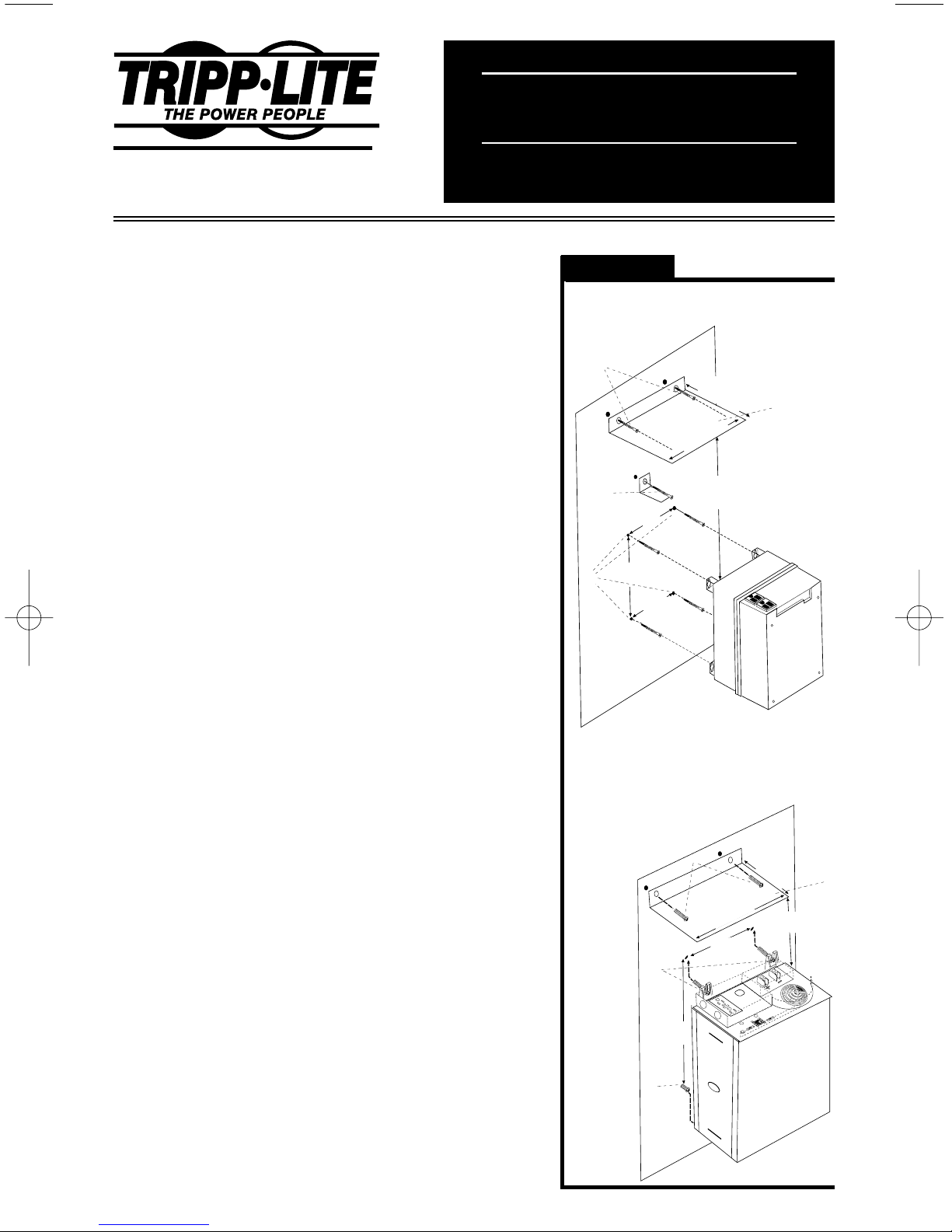
Wallmounting for the PV 500FC,PV 1000FC or APS 512
(See Diagram 1)
• Install four 5mm (#8) fasteners (A) into a rigid vertical surface using
the measurements in the diagram.Leave the heads of the fasteners
raised slightly above the surface in order to engage the keyhole
slots molded into the bottom of the PowerVerter's feet.
• Place keyhole slots in the PowerVerter's four feet over the four fasteners and slide the PowerVerter forward or down to secure it.The
control panel should face up.Install an "L"-shaped bracket (B) as
shown to secure the PowerVerter.
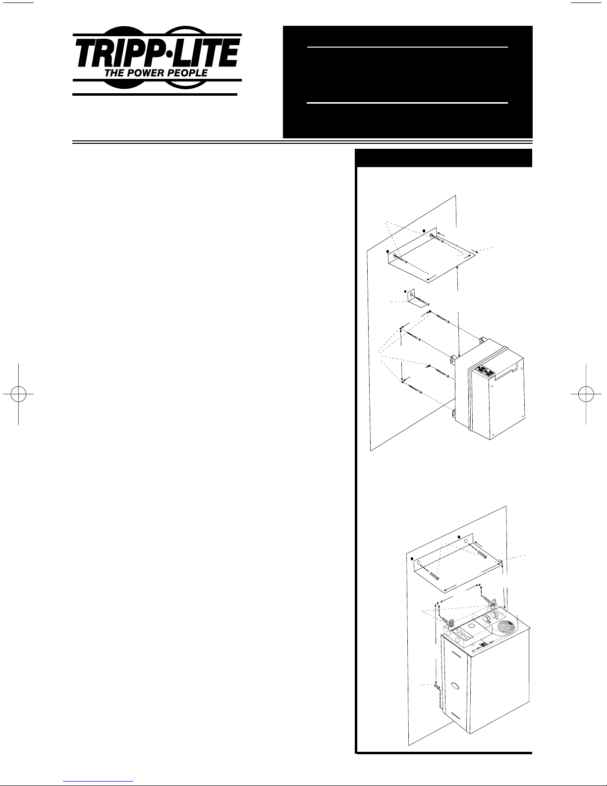
Wallmounting for the PV 2000FC,PV 2400FC, APS 1012, APS 1024,
APS 2012, APS 2424, APS 2448 or APS 3636
(See Diagram 2)
• Install two 8 mm (1/4 in.) fasteners (A) into a rigid vertical surface
using the measurements in the diagram.Leave the heads of
fasteners raised slightly above the surface in order to engage
the slots in the PowerVerter's feet.
• Slide PowerVerter up to fully engage the fasteners in the
PowerVerter's front feet.The PowerVerter’s control panel should
face up.Install two 8 mm (1/4 in.) fasteners (B) into the surface,
through the slots in the PowerVerter's two unsecured bottom feet.
Tighten the screws to permanently hold the PowerVerter in position.
Installing a Drip Guard
(See Diagram 1 or 2)
• A drip guard is recommended when wallmounting all PowerVerter
models.Leave a space between the PowerVerter and the guard to
allow for proper ventilation to the inverter.Use sheet metal screws
(C) to mount a sheet metal splash guard (D) measuring as shown
4" to 6" above the control panel of the PowerVerter.User must supply drip guard, screws and spacers.
1111 W. 35th Street • Chicago, IL 60609 USA
Customer Support: (773) 869-1234
www.tripplite.com
Owner's Manual Addendum
PowerVerter
Wallmount Instructions
For PowerVerter Plus and
PowerVer ter APS Models
Copyright © 2001 Tripp Lite. All rights reserved.
PowerVerter®is a registered trademark of Tripp Lite.
Diagram 1
Mounting for PV 500FC, PV 1000FC and APS 512
Diagram 2
Mounting for
PV 2000FC, PV 2400FC, APS 1012, APS 1024,
APS 2012, APS 2424, APS 2448, APS 3636
51/2"
(14.1 cm)
5"
(12.7 cm)
61/8"
(15.7 cm)
(20.5 cm)
8"
8"
(20.5 cm)
C
B
A
D
4 - 6"
(10 - 15 cm)
B
A
C
D
57/8"
(15cm)
151/8"
(39cm)
4-6"
(10-15cm)
9
1
/
2
"
(24.5cm)
8
1
/
2
"
(22cm)
Diagrams
Page 2
2
93-1962 200105046
CONSERVE ESTE SUPLEMENTO DEL MANUAL DE OPERACION.
Contiene instrucciones importantes que deben seguirse durante la
instalación en la pared de los Sistemas PowerVerter de Tripp Lite.
Advertencias
• Este procedimiento de montaje en la pared no ha sido probado o
certificado por Underwriter Laboratories.
• Si desea utilizar el PowerVerter en un vehículo, instálelo sobre una
superficie horizontal, no sobre una superficie vertical.
• Monte el PowerVerter bajo techo, alejado de humedad y calor
excesivo, polvo o luz solar directa.
• Conserve suficiente espacio alrededor del PowerVerter para permi
tir ventilación adecuada. Cuanto más energía demanden los
equipos conectados, más calor generará el PowerVerter.
• No instale el PowerVerter cerca de medios magnéticos de almace
namiento de datos. Esto podría resultar en la corrupción de los
datos contenidos en dicho medio de almacenamiento.
Procedimiento del Montaje en la Pared
El usuario debe suministrar todos los sujetadores y soportes y debe
verificar que todos éstos sean adecuados para su uso en la superficie
deseada. Apague el PowerVerter y todos los equipos conectados
antes de comenzar el proceso de montaje.
Montaje en la pared para los modelos PV 500FC, PV 1000FC
ó APS 512
(Vea el Diagrama 1)
• Instale cuatro sujetadores de 5mm (#8) (A) en una superficie rígida
vertical utilizando las medidas especificadas en el diagrama.
Permita que las cabezas de los sujetadores sobresalgan ligeramente de la superficie para encajarlos en las ranuras de las patas
del Pow erVerter.
• Coloque las ranuras ubicadas en las cuatro patas del PowerVerter
sobre los cuatro sujetadores y deslice el PowerVerter hacia adelante o hacia abajo para asegurarlo. El panel de control debe estar
ubicado hacia arriba. Instale un soporte en forma de “L” (B) como
se indica en el diagrama para asegurar el PowerVerter.
Montaje en la pared para los modelos PV 2000FC, PV 2400FC,
APS 1012, APS 1024, APS 2012, APS 2424, APS 2448 ó APS 3636
(Vea el Diagrama 2)
• Instale dos sujetadores de 8mm (1/4 pulgada) (A) en una superficie
rígida vertical utilizando las medidas en el diagrama. Permita que
las cabezas de los sujetadores sobresalgan ligeramente sobre la
superficie para encajar las ranuras ubicadas en las patas del
Pow erVerter .
• Deslice el PowerVerter para que las ranuras ubicadas en las patas
frontales del mismo encajen en los sujetadores correspondientes.
El panel de control del PowerVerter debe estar ubicado hacia
arriba. Instale dos sujetadores de 8mm (1/4 pulgada) (B) en la
superficie y a través de las ranuras ubicadas en las dos patas
restantes del PowerVerter. Apriete los tornillos para sujetar el
PowerVerter permanentemente en esta posición.
Instalación de un Protector contra Salpicaduras
(Vea el Diagrama 1 ó 2)
• Se recomienda la instalación de un protector contra salpicaduras
en todos los montajes de pared de los modelos PowerVerter. Deje
un espacio entre el PowerVerter y el protector para permitir ventilación adecuada. Utilice tornillos para chapas (C) para instalar un
protector contra salpicaduras (D) utilizando las medidas especificadas y a una distancia de 4 a 6 pulgadas del panel de control del
PowerVerter. El usuario debe suministrar la chapa de protección,
tornillos y separadores.
1111 W. 35th Street • Chicago, IL 60609 USA
Servicios a Clientes: (773) 869-1234
www.tripplite.com
Suplemento del Manual de Operación
PowerVerter
Instrucciones para
Montaje en la Pared
De los Modelos PowerVer ter Plus
y PowerVer ter APS
Copyright © 2001 Tripp Lite. Reservados todos los derechos.
PowerVerter®es una marca registrada de Tripp Lite.
Diagramas Esquemáticos
Diagrama 1
Montaje de los modelos PV 500FC, PV 1000FC
and APS 512
Diagrama 2
Montaje de los modelos
PV 2000FC, PV 2400FC, APS 1012, APS 1024,
APS 2012, APS 2424, APS 2448, APS 3636
51/2"
(14.1 cm)
5"
(12.7 cm)
61/8"
(15.7 cm)
(20.5 cm)
8"
8"
(20.5 cm)
C
B
A
D
4 - 6"
(10 - 15 cm)
B
A
C
D
57/8"
(15cm)
151/8"
(39cm)
4-6"
(10-15cm)
9
1
/
2
"
(24.5cm)
8
1
/
2
"
(22cm)
 Loading...