

Page 1

Warranty
Registration:
register online today for a
chance to win a FREE Tripp Lite
product—www.tripplite.com/warranty
Console Server Management Switch
Owner’s Manual
Models: B096-016 / B096-048
&
Console Server with PowerAlert
Model: B092-016
Tripp Lite World Headquarters
1111 W. 35th Street, Chicago, IL 60609 USA
(773) 869-1234 (USA) • 773.869.1212 (International)
www.tripplite.com
Copyright © 2009 Tripp Lite. All rights reserved. All trademarks are the property of their respective owners.
1
Page 2

INDEX
1. INTRODUCTION 9
2. INSTALLATION 14
2.1 Models 14
2.1.1 Kit components: B096-048 and B096-016 Console Server Management Switch 14
2.1.2 Kit components: B092-016 Console Server with PowerAlert 15
2.2 Power connection 15
2.2.1 Power: Console Server Management Switch 15
2.2.2 Power: Console Server with PowerAlert 16
2.3 Network connection 16
2.4 Serial Port connection 16
2.5 USB Port Connection 17
2.6 Rackmount Console / KVM Connection (B092-016 only) 17
3. INITIAL SYSTEM CONFIGURATION 18
3.1 Management Console Connection 18
3.1.1 Connected computer set up 18
3.1.2 Browser connection 19
3.1.3 Initial B092-016 connection 21
3.2 Administrator Password 21
3.3 Network IP address 22
3.3.1 IPv6 configuration 23
3.4 System Services 24
3.5 Communications Software 27
3.5.1 SDT Connector 27
3.5.2 PuTTY 27
3.5.3 SSHTerm 28
3.6 Management Network Configuration (B096-048/016 only) 29
3.6.1 Configure Management Switch as a Management LAN gateway 29
3.6.3 Configure Management Switch for Failover or broadband OOB 32
4. SERIAL PORT AND NETWORK HOST 33
4.1 Configuring Serial Ports 33
4.1.1 Common Settings 34
4.1.2 Console Server Mode 35
2
Page 3

4.1.3 SDT Mode 39
4.1.4 Device (RPC, UPS, EMD) Mode 39
4.1.5 Terminal Server Mode 39
4.1.6 Serial Bridging Mode 40
4.1.7 Syslog 41
4.2 Add/Edit Users 41
4.3 Authentication 44
4.4 Network Hosts 44
4.5 Trusted Networks 46
4.6 Serial Port Cascading 47
4.6.1 Automatically generate and upload SSH keys 47
4.6.2 Manually generate and upload SSH keys 48
4.6.3 Configure the Slaves and their serial ports 50
4.6.4 Managing the Slaves 51
5. FAILOVER AND OUT-OF-BAND ACCESS 52
5.1 OoB Dial-In Access 52
5.1.1 Configure dial-in PPP 52
5.1.2 Using SDT Connector client for dial-in 54
5.1.3 Set up Windows XP/ 2003/Vista client for dial-in 54
5.1.4 Set up earlier Windows clients for dial-in 55
5.1.5 Set up Linux clients for dial-in 56
5.2 OoB Broadband Access (B096-048/016 only) 56
5.3 Broadband Ethernet Failover (B096-048/016 only) 56
5.4 Dial-Out Failover 58
6. SECURE TUNNELING AND SDT CONNECTOR 60
6.1 Configuring for SDT Tunneling to Hosts 61
6.2 SDT Connector Configuration 61
6.2.1 SDT Connector client installation 62
6.2.2 Configuring a new gateway in the SDT Connector client 63
6.2.3 Auto-configure SDT Connector client with the user’s access privileges 64
6.2.4 Make an SDT connection through the gateway to a host 65
6.2.5 Manually adding hosts to the SDT Connector gateway 66
6.2.6 Manually adding new services to the new hosts 67
6.2.7 Adding a client program to be started for the new service 69
6.2.8 Dial- in configuration 70
3
Page 4

6.2.9 Choosing an alternate SSH client (e.g. PuTTY) 70
6.3 SDT Connector to Management Console 75
6.4 SDT Connector - Telnet or SSH connect to serially attached devices 76
6.5 Using SDT Connector for out-of-band connection to the gateway 77
6.6 Importing (and exporting) preferences 79
6.7 SDT Connector Public Key Authentication 79
6.8 Setting up SDT for Remote Desktop access 80
6.8.1 Enable Remote Desktop on the target Windows computer to be accessed 80
6.8.2 Configure the Remote Desktop Connection client 81
6.9 SDT SHH Tunnel for VNC 85
6.9.1 Install and configure the VNC Server on the computer to be accessed 85
6.9.2 Install, configure and connect the VNC Viewer 86
6.10 Using SDT to IP connect to hosts that are serially attached to the gateway 88
6.10.1 Establish a PPP connection between the host COM port and Console Server 88
6.10.2 Set up SDT Serial Ports on Console Server 91
6.10.3 Set up SDT Connector to ssh port forward over the Console Server Serial Port 92
7. ALERTS AND LOGGING 93
7.1 Configure SMTP/SMS/SNMP/Nagios alert service 93
7.1.1 Email alerts 93
7.1.2 SMS alerts 94
7.1.3 SNMP alerts 95
7.1.4 Nagios alerts 96
7.2 Activate Alert Events and Notifications 96
7.2.1 Add a new alert 97
7.2.2 Select general alert type 98
7.2.3 Configuring environment and power alert type 99
7.3 Remote Log Storage 100
7.4 Serial Port Logging 101
7.5 Network TCP or UDP Port Logging 102
POWER & ENVIRONMENTAL MANAGEMENT 103
8.1 Remote Power Control (RPC) 103
8.1.1 RPC connection 103
8.1.2 RPC alerts 105
8.1.3 RPC status 105
4
Page 5

8.1.4 User power management 105
8.2 Uninterruptible Power Supply Control (UPS) 106
8.2.1 Managed UPS connections 106
8.2.2 Configure UPS powering the Console Server 109
8.2.3 Configuring powered computers to monitor a Managed UPS 110
8.2.4 UPS alerts 111
8.2.5 UPS status 111
8.2.6 Overview of Network UPS Tools (NUT) 111
8.3 Environmental Monitoring 113
8.3.1 Connecting the EMD 114
8.3.2 Environmental alerts 115
8.3.3 Environmental status 115
AUTHENTICATION 117
9.1 Authentication Configuration 117
9.1.1 Local authentication 118
9.1.2 TACACS authentication 118
9.1.3 RADIUS authentication 119
9.1.4 LDAP authentication 120
9.1.5 RADIUS/TACACS user configuration 121
9.2 PAM (Pluggable Authentication Modules) 122
9.3 Secure Management Console Access 123
NAGIOS INTEGRATION 125
10.1 Nagios Overview 125
10.2 Central management 126
10.2.1 Set up central Nagios server 126
10.2.2 Set up distributed Console Servers 127
10.3 Configuring Nagios distributed monitoring 129
10.3.1 Enable Nagios on the Console Server 129
10.3.2 Enable NRPE monitoring 131
10.3.3 Enable NSCA monitoring 132
10.3.4 Configure selected Serial Ports for Nagios monitoring 132
10.3.5 Configure selected Network Hosts for Nagios monitoring 133
10.3.6 Configure the upstream Nagios monitoring host 134
10.4 Advanced Distributed Monitoring Configuration 135
10.4.1 Sample Nagios configuration 135
5
Page 6

10.4.2 Basic Nagios plug-ins 138
10.4.3 Additional plug-ins 138
11. SYSTEM MANAGEMENT 140
11.1 System Administration and Reset 140
11.2 Upgrade Firmware 141
11.3 Configure Date and Time 142
12. STATUS REPORTS 143
12.1 Port Access and Active Users 143
12.2 Statistics 143
12.3 Support Reports 144
12.4 Syslog 144
13. MANAGEMENT 146
13.1 Device Management 146
13.2 Port and Host Management 146
13.3 Power Management 147
13.4 Serial Port Terminal Connection 147
13.5 Remote Console Access (B092-016 only) 149
14. BASIC CONFIGURATION - LINUX COMMANDS 151
14.1 The Linux Command line 152
14.2 Administration Configuration 154
System Settings 154
Authentication Configuration 154
14.3 Date and Time Configuration 155
14.4 Network Configuration 156
IP Configuration 156
Dial-in Configuration 157
Services Configuration 158
14.5 Serial Port Configuration 159
Serial Port Settings 159
Supported Protocol Configuration 160
Users 160
Trusted Networks 161
14.6 Event Logging Configuration 162
Remote Serial Port Log Storage 162
6
Page 7

Alert Configuration 163
14.7 SDT Host Configuration 163
SDT Host TCP Ports 163
14.8 Configuration backup and restore 165
14.9 General Linux command usage 166
15. ADVANCED CONFIGURATION 168
15.1 Advanced Portmanager 169
15.2 External Scripts and Alerts 171
15.3 Raw Access to Serial Ports 173
15.4 IP- Filtering 174
15.5 Modifying SNMP Configuration 176
Adding more than on SNMP server 177
15.6 Secure Shell (SSH) Public Key Authentication 178
SSH Overview 178
Generating Public Keys (Linux) 179
Installing the SSH Public/Private Keys (Clustering) 180
Installing SSH Public Key Authentication (Linux) 180
Generating Public/Private keys for SSH (Windows) 182
Fingerprinting 184
SSH tunneled serial bridging 185
SDT Connector Public Key Authentication 188
15.7 Secure Sockets Layer (SSL) Support 189
15.8 HTTPS 190
15.9 Power Strip Control 192
PowerMan 192
pmpower 194
Adding new RPC devices 194
15.10 IPMItool 196
15.11 Scripts for Managing Slaves 200
16. THIN CLIENT (B092-016) 202
16.1 Local Client Service Connections 202
16.1.1 Connect- serial terminal 204
16.1.2 Connect- browser 204
16.1.3 Connect- VNC 205
7
Page 8

16.1.4 Connect- SSH 206
16.1.5 Connect- IPMI 207
16.1.6 Connect- Remote Desktop (RDP) 208
16.1.7 Connect- Citrix ICA 209
Connect- PowerAlert 209
16.1.8
16.2 Advanced Control Panel 210
16.2.1 System: Terminal 210
16.2.2 System: Shutdown / Reboot 211
16.2.3 System: Logout 211
16.2.4 Custom 211
16.2.5 Status 211
16.2.6 Logs 211
16.3 Remote control 212
Appendix A Hardware Specification 213
Appendix B Serial Port Connectivity 214
Appendix C End User License Agreement 216
Appendix D Service and Warranty 223
8
Page 9

1. INTRODUCTION
This Manual
This User Manual is provided to help you get the most from your B096-016 / B096-048 Console Server
Management Switch or B092-016 Console Server with PowerAlert product. These products are referred
to generically in this manual as Console Servers.
Once configured, you will be able to use your Console Server to securely monitor, access and control the
computers, networking devices, telecommunications equipment, power supplies and operating
environment in your data center, branch office or communications room. This manual guides you in
managing this infrastructure locally (at the rack side or across your operations or management LAN or
through the local serial console port), and remotely (across the Internet, private network or via dial up).
FCC Information
This is an FCC Class A product. In a domestic environment this product may cause radio interference in
which case the user may be required to take adequate measures. This equipment has been tested and
found to comply with the limits for a Class A digital device, pursuant to Part 15 of the FCC Rules. These
limits are designed to provide reasonable protection against harmful interference when the equipment
is operated in a commercial environment.
This equipment generates, uses and can radiate radio frequency energy and, if not installed and used in
accordance with the instruction manual, may cause harmful interference to radio communications.
Operation of this equipment in a residential area is likely to cause harmful interference, in which case
the user will be required to correct the interference at his own expense.
RoHS
This product is RoHS compliant.
User Notice
All information, documentation and specifications contained in this manual are subject to change
without prior notification by the manufacturer. The manufacturer makes no representations or
warranties, either expressed or implied, with respect to the contents hereof and specifically disclaims
any warranties as to merchantability or fitness for any particular purpose. Any of the manufacturer's
software described in this manual is sold or licensed `as is'. Should the programs prove defective
following their purchase, the buyer (and not the manufacturer, its distributor, or its dealer), assumes the
entire cost of all necessary servicing, repair and any incidental or consequential damages resulting from
any defect in the software.
The manufacturer of this system is not responsible for any radio and/or TV interference caused by
unauthorized modifications to this device. It is the responsibility of the user to correct such interference.
The manufacturer is not responsible for any damage incurred in the operation of this system if the
correct operational voltage setting was not selected prior to operation.
RODUCTION
9
Page 10
Please take care to follow the safety precautions below when installing and
operating the Console Server:
Do not remove the metal covers. There are no operator-serviceable
components inside. Opening or removing the cover may expose you to
dangerous voltage which may cause fire or electric shock. Refer all service
to Tripp Lite qualified personnel
To avoid electric shock the power cord protective grounding conductor
must be connected through to ground
Always pull on the plug, not the cable, when disconnecting the power cord
from the socket
Do not connect or disconnect the Console Server during an electrical storm
Also it is recommended you use a surge suppressor or UPS to protect the
equipment from transients
Manual Organization
This User Manual covers all aspects of installation, configuration and operation and an overview of the
information found in the manual is provided below.
1. Introduction An overview of the features of the Console Server and information on
this manual
2. Installation Details physical installation of the Console Server and the
interconnection of controlled devices
3. System Configuration Describes the initial installation and configuration using the
Management Console of the Console Server on the network and the
services that will be supported
4. Serial and Network Covers configuring serial ports and connected network hosts, and
setting up Users and Groups
5. Failover and OoB dial-in Describes setting up the high-availability access features of the Console
Server
6. Secure Tunneling (SDT) Covers secure remote access using SSH and configuring for RDP, VNC,
HTTP, HTTPS, etc. access to network and serially connected devices
7. Alerts and Logging Explains the setting up of local and remote event/ data logs and
triggering SNMP and email alerts
8. Power & Environment Management of USB, serial and network attached Power Distribution
units and UPS units including Network UPS Tool (NUT) operation and
IPMI power control. EMD environmental sensor configuration
9. Authentication All access to the Console Server requires usernames and passwords
which are locally or externally authenticated
10
Page 11

10. Nagios Integration Setting Nagios central management with SDT extensions and
configuring the Console Server as a distributed Nagios server
11. System Management Covers access to and configuration of services to be run on the Console
Server
12. Status Reports View the status and logs of serial and network connected devices (ports,
hosts, power and environment)
13. Management Includes port controls and reports that can accessed by Users
14. Basic Configuration Command line installation and configuration using the config command
15. Advanced Config More advanced command line configuration activities where you will
need to use Linux commands
16. Thin Client Configuration and use of the thin client and other applications (including
Power Alert) embedded in the Console Server with PowerAlert (B092-
016) product
Types of users
The Console Server supports two classes of users:
I. Administrative users: Those who will be authorized to configure and control the Console Server; and
to access and control all the connected devices. These administrative users will be set up as members
of the admin user group. Any user in this class is referred to generically in this manual as an
Administrator. An Administrator can access and control the Console Server using the config utility,
the Linux command line or the browser-based Management Console. By default the Administrator
has access to all services and ports to control all the serial connected devices and network connected
devices (hosts).
II. Users: Embraces those who have been set up by the Administrator with specific limits on their
access and control authority. These users are set up as members of the users user group (or some
other user groups the Administrator may have added). They are only authorized to perform specified
controls on specific connected devices and are referred to as Users. These Users (when authorized)
can access serial or network connected devices; and control these devices using the specified
services (e.g. Telnet, HHTPS, RDP, IPMI, Serial over LAN, Power Control). An authorized User can also
use the Management Console to access configured devices and review port logs.
In this manual, when the term user (lower case) is used, it is referring to both the above classes of users.
This document also uses the term remote users to describe users who are not on the same LAN segment
as the Console Server. These remote users may be Users, who are on the road connecting to managed
devices over the public Internet, or it may be an Administrator in another office connecting to the
Console Server itself over the enterprise VPN, or the remote user may be in the same room or the same
office but connected on a separate VLAN to the Console Server.
Management Console
The Console Server Management Console runs in a browser. It provides a view of your Console Server
Management Switch (B096-016/048) or Console Server with PowerAlert (B092-016) product and all the
connected equipment. Administrators can use the Management Console, either locally or from a remote
11
Page 12
location, to configure the Console Server, set up Users, configure the ports and connected hosts, and set
up logging and alerts.
An authorized User can use the Management Console to access and control configured devices, review
port logs, use the in-built java terminal to access serially attached consoles and control power to
connected devices.
The Console Server runs an embedded Linux operating system. Experienced Linux and UNIX users may
prefer to undertake configuration at the command line. As an Administrator you can get command line
access by connecting through a terminal emulator or communications program to the console serial
port; or by SSH or Telnet connecting to the Console Server over the LAN; or by connecting to the
Console Server through an SSH tunnel using the SDTConnector.
The B092-016 Console Server also has PowerAlert software and a selection of thin clients embedded
(RDP, Firefox etc). You will be able to use these consoles as well as the standard Management Console
for access and control.
Manual Conventions
This manual uses different fonts and typefaces to show specific actions:
Note Text presented like this indicates issues which need to be noted
12
Page 13
Text presented like this highlights important issues and it is essential you read
and take heed of these warnings
Text presented with an arrow head indent indicates an action you should take as part of the
procedure.
Bold text indicates text that you type, or the name of a screen object (e.g. a menu or button) on the
Management Console.
Italic text is also used to indicate a text command to be entered at the command line level.
Publishing history
Date Revision Update details
January 2009 0.9 Initial draft
February 2009 0.91 Pre-release
13
Page 14
2. INSTALLATION
Introduction
This chapter describes the physical installation of the Console Server hardware and connection to
controlled devices
2.1 Models
There are a number of Console Server models, each with a different number of network, USB and serial
ports and power supplies:
Serial
Ports
B096-048 48 2 1 1 Internal Dual AC Universal Input
B096-016 16 2 1 1 Internal Dual AC Universal Input
B092-016 16 1 1+KVM 4 - Single AC Universal Input
Network
Ports
Console
Port
USB
Port
Modem Power
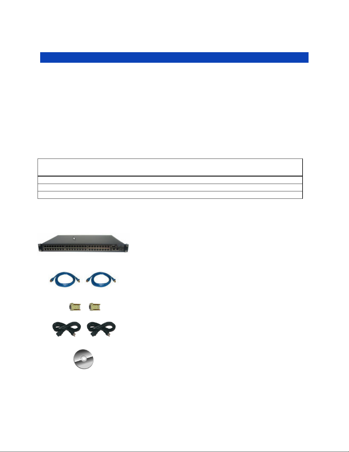
2.1.1 Kit components: B096-048 and B096-016 Console Server Management Switch
Unpack your Console Server Management Switch kit and verify you have all the parts shown
above, and that they all appear in good working order
B096-048 or B096-016
Console Server Management Switch
2 x Cable UTP Cat5 blue
Connectors
DB9F-RJ45S straight and cross-over
Dual IEC AC power cords
Quick Start Guide and CD-ROM
14
Page 15

If you are installing your Console Server Management Switch in a rack you will need to attach
the rack mounting brackets supplied with the unit, and install the unit in the rack. Take care to
head the Safety Precautions
Connect your Console Server Management Switch to the network, to the serial ports of the
controlled devices, and to power as outlined below
2.1.2 Kit components: B092-016 Console Server with PowerAlert
Unpack your Console Server and verify you have all the parts shown above, and that they all
appear in good working order
If you are installing your Console Server in a rack, you will need to attach the rack mounting
brackets supplied with the unit, and install the unit in the rack. Take care to heed the Safety
Precautions listed earlier
B092-016
Console Server with PowerAlert
2 x Cable UTP Cat5 blue
Connector DB9F-RJ45S straight and DB9FRJ45S cross-over
AC power cable
Quick Start Guide and CD-ROM
Proceed to connect your B092-016 to the network, to the serial and USB ports of the controlled
devices, to any rack side LCD console or KVM switch, and to power as outlined below
2.2 Power connection
2.2.1 Power: Console Server Management Switch
The B096-048/16 Console Server Management Switch has dual universal AC power supplies with auto
failover built in. These power supplies each accept AC input voltage between 100 and 240 VAC with a
frequency of 50 or 60 Hz and the total power consumption per Console Server is less than 30W. Two IEC
AC power sockets are located at the rear of the metal case, and these IEC power inlets use conventional
IEC AC power cords. A North American power cord is provided by default. Power cords for other regions
are available separately from Tripp Lite.
15
Page 16

2.2.2 Power: Console Server with PowerAlert
The standard B092-016 Console Server has a built-in universal auto-switching AC power supply. This
power supply accepts AC input voltage between 100 and 240 VAC with a frequency of 50 or 60 Hz and
the power consumption is less than 40W.
The AC power socket is located at the rear of the B092-016. This power inlet uses a conventional AC
power cord. A North American power cord is provided by default. Power cords for other regions are
available separately from Tripp Lite.
2.3 Network connection
The RJ45 10/100 LAN port is located on the rear of the B092-016 Console Server, and on the front of the
B096-048/016 Console Server Management Switch. All physical connections are made using industry
standard Cat5e patch cables (Tripp Lite N001 and N002 series cables). Ensure you only connect the LAN
port to an Ethernet network that supports 10Base-T/100Base-T. For the initial configuration of the
Console Server you must connect a computer to the Console Server’s principal network port.
2.4 Serial Port connection
The RJ45 serial ports are located on the rear of the B092-016 Console Server and on the front of the
B096-048/016 Console Server Management Switch. These Console Servers use the RJ45 pinout used by
Cisco. Use straight through RJ-45 cabling to connect to equipment such as Cisco, Juniper, SUN, and
more.
PIN SIGNAL DEFINITION DIRECTION
1 CTS Clear To Send Input
2 DSR Data Set Ready Input
3 RXD Receive Data Input
Conventional Cat5 cabling with RJ45 jacks are used for serial connections. Before connecting the console
port of an external device to the Console Server serial port, confirm that the device supports standard
RS-232C (EIA-232).
4 GND Signal Ground NA
5 GND Signal Ground NA
6 TXD Transmit Data Output
7 DTR Data Terminal Ready Output
8 RTS Request To Send Output
16
Page 17

The Console Server also has a DB9 LOCAL (Console/Modem) port. This DB-9 connector is on the rear
panel of the B092-016 Console Server, and on the front panel of the B096-048/016 Console Server
Management Switch.
2.5 USB Port Connection
The B096-048/016 Console Server Management Switch has one USB port on the front panel. External
USB devices can be plugged into this USB port. The B096-048/016 Console Server Management Switch
ships with a USB memory stick so that it will be installed in this port for extended log file storage.
There are four USB 2.0 ports on the rear panel of the B092-016 Console Server. These ports are used to
connect to USB consoles (of managed UPS hardware) and to other external devices (such as a USB
memory stick or keyboard).
External USB devices (including USB hubs) can be plugged into any Console Server USB port.
2.6 Rackmount Console / KVM Connection (B092-016 only)
B092-016 Console Server with PowerAlert can be connected directly to a rack mount console (such as
B021-000-17 or B021-019 by Tripp Lite) to provide direct local management right at the rack. Connect
the rack mount console’s PS/2 Keyboard/Mouse and VGA connectors directly to the PS/2 and VGA
connectors on the B092-016. The default video resolution is 1024 x768. The B092-016 Console Server
also supports the use of a USB keyboard/mouse.
Alternately, the B092-016 Console Server can also be connected locally to a KVM (or KVMoIP) switch at
the rack. The B092-016 Console Server with PowerAlert will enable you then to use this KVM
infrastructure to run PowerAlert, to manage your power devices and to run the thin clients to manage
other devices.
Note Care should be taken in handling all Console Server products. There are no operator-serviceable
components inside, so do not remove cover. Refer any service to qualified personnel
17
Page 18

3. INITIAL SYSTEM CONFIGURATION
Introduction
This chapter provides step-by-step instructions for the initial configuration of your Console Server and
connecting it to your management or operational network. This involves the Administrator:
Activating the Management Console
Changing the Administrator password
Setting the IP address for the Console Server’s principal LAN port
Selecting the network services to be supported
This chapter also discusses the communications software tools that the Administrator may use to access
the Console Server. It also covers the configuration of the additional LAN ports on the B096-016/048
Console Server Management Switch.
3.1 Management Console Connection
Your Console Server has a default IP Address 192.168.0.1 Subnet Mask 255.255.255.0
Directly connect a computer to the Console Server
Note For initial configuration it is recommended that the Console Server be connected directly to a
single computer. However, if you choose to connect your LAN before completing the initial setup
steps, it is important that:
you ensure there are no other devices on the LAN with an address of 192.168.0.1
the Console Server and the computer are on the same LAN segment, with no interposed router
3.1.1 Connected computer set up
To configure the Console Server with a browser, the connected computer should have an IP address in
the same range as the Console Server (e.g. 192.168.0.100):
appliances
To configure the IP Address of your Linux or Unix computer simply run ifconfig
For Windows computers (Win9x/Me/2000/XP/ Vista/ NT):
Click Start -> (Settings ->) Control Panel and double click Network Connections (for
95/98/Me, double click Network).
Right-click on Local Area Connection and select Properties
Select Internet Protocol (TCP/IP) and click Properties
Select Use the following IP address and enter the following details:
18
Page 19
o IP address: 192.168.0.100
o Subnet mask: 255.255.255.0
If you wish to retain your existing IP settings for this network connection, click Advanced
and Add the above as a secondary IP connection.
If it is not convenient to change your computer network address, you can use the ARP-Ping
command to reset the Console Server IP address. To do this from a Windows computer:
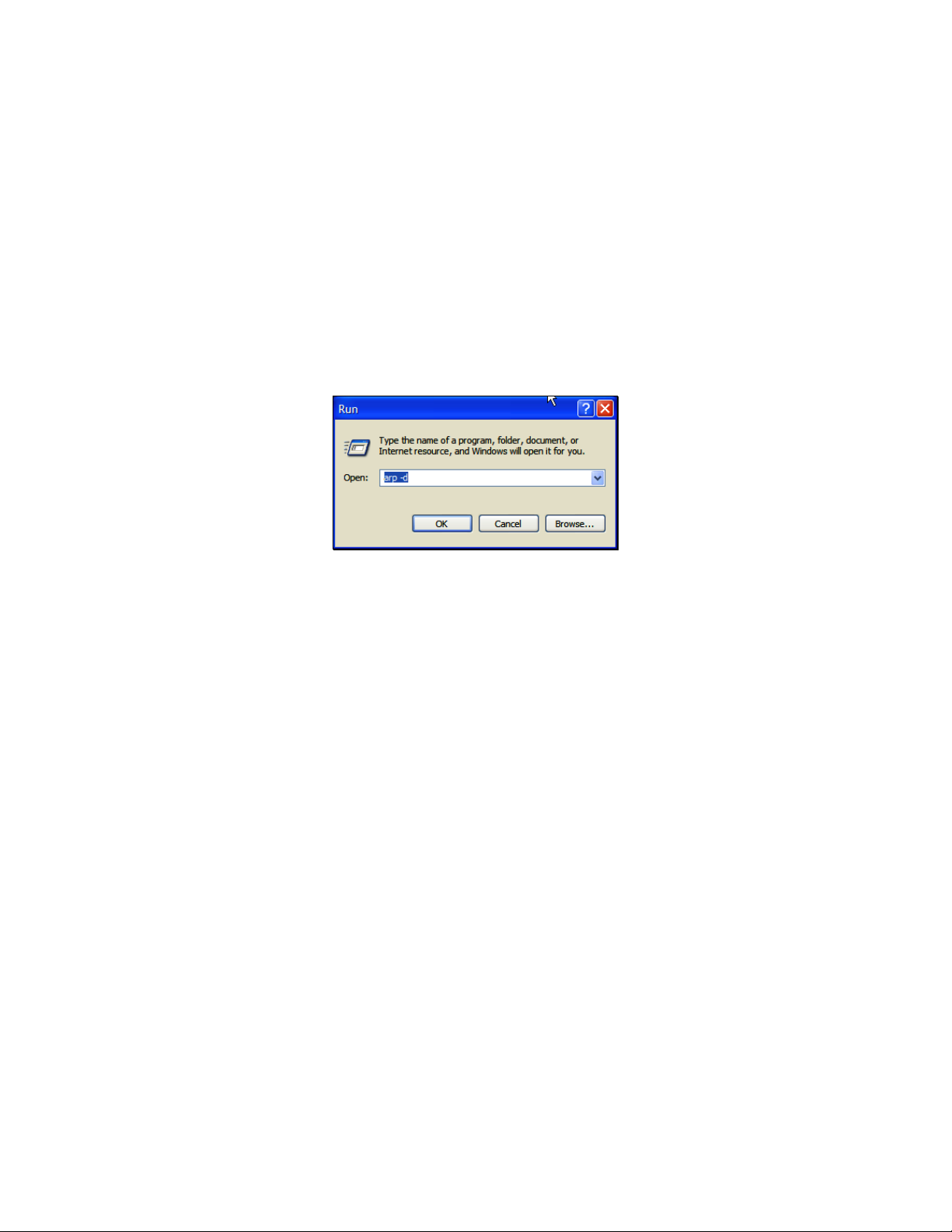
Click Start -> Run
Type cmd and click OK to bring up the command line
Type arp –d to flush the ARP cache
Type arp –a to view the current ARP cache which should be empty
Now add a static entry to the ARP table and ping the Console Server to have it get the IP
address. In the example below we have a Console Server with a MAC Address 00:13:C6:00:02:0F
(designated on the label on the bottom of the unit) and we are setting its IP address to
192.168.100.23. The computer issuing the arp command must be on the same network segment
as the Console Server (i.e. have an IP address of 192.168.100.xxx)
Type arp -s 192.168.100.23 00-13-C6-00-02-0F (Note for UNIX the syntax is: arp -s
192.168.100.23 00:13:C6:00:02:0F)
Type ping -t 192.18.100.23 to start a continuous ping to the new IP Address.
Turn on the Console Server and wait for it to configure itself with the new IP address. It will
start replying to the ping at this point
Type arp –d to flush the ARP cache again
3.1.2 Browser connection
Activate your preferred browser on the connected computer and enter https://192.168.0.1 The
Console Server supports all current versions of the popular browsers (Netscape, Internet
Explorer, Mozilla Firefox and more)
19
Page 20
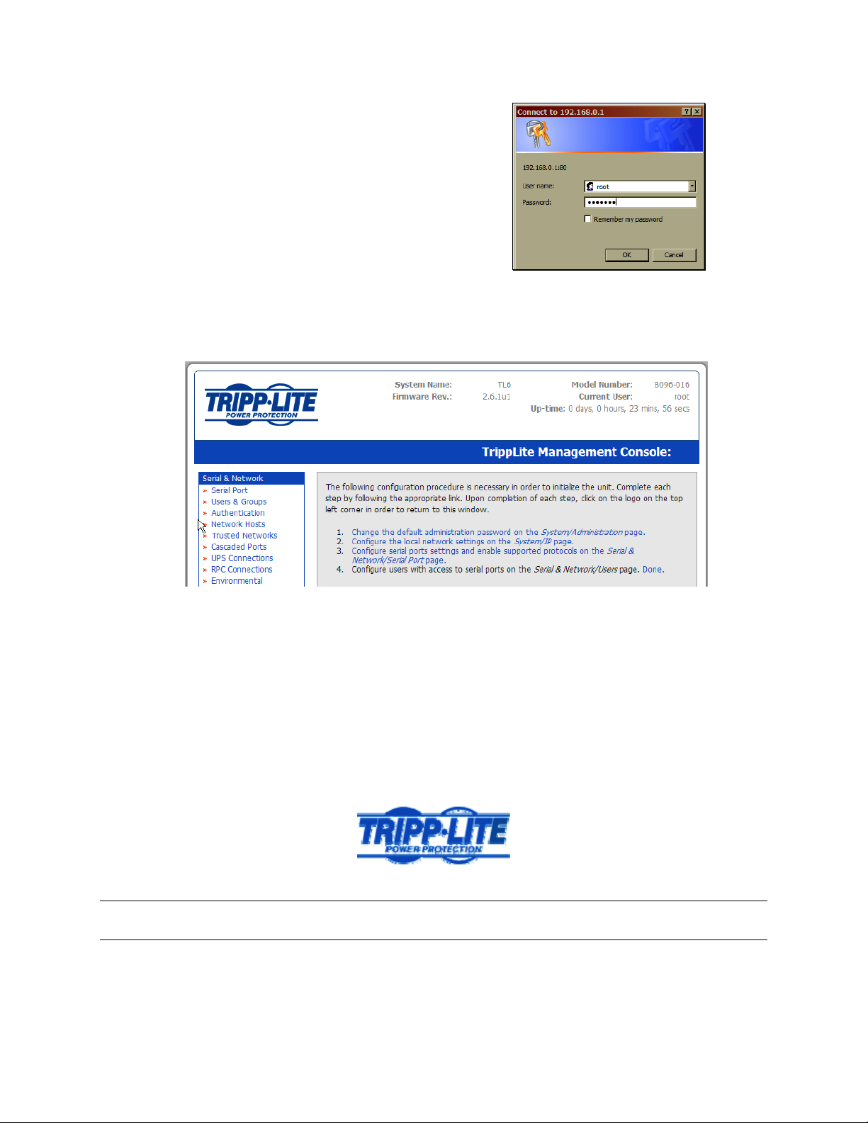
You will be prompted to log in. Enter the default
administration username and administration
password:
Username: root
Password: default
The above screen, which lists four initial installation configuration steps, will be displayed:
1. Change the default administration password on the System/Administration page (Chapter 3)
2. Configure the local network settings on the System/IP page (Chapter 3)
3. Configure port settings and enable the Serial & Network/Serial Port page (Chapter 4)
4. Configure users with access to serial ports on the Serial & Network/Users page (Chapter 3)
After completing each of the above steps, you can return to the configuration list by clicking in the top
left corner of the screen on the logo:
Note If you are not able to connect to the Management Console at 192.168.0.1 or if the default
Username / Password were not accepted then reset your Console Server (refer to Chapter 10)
20
Page 21
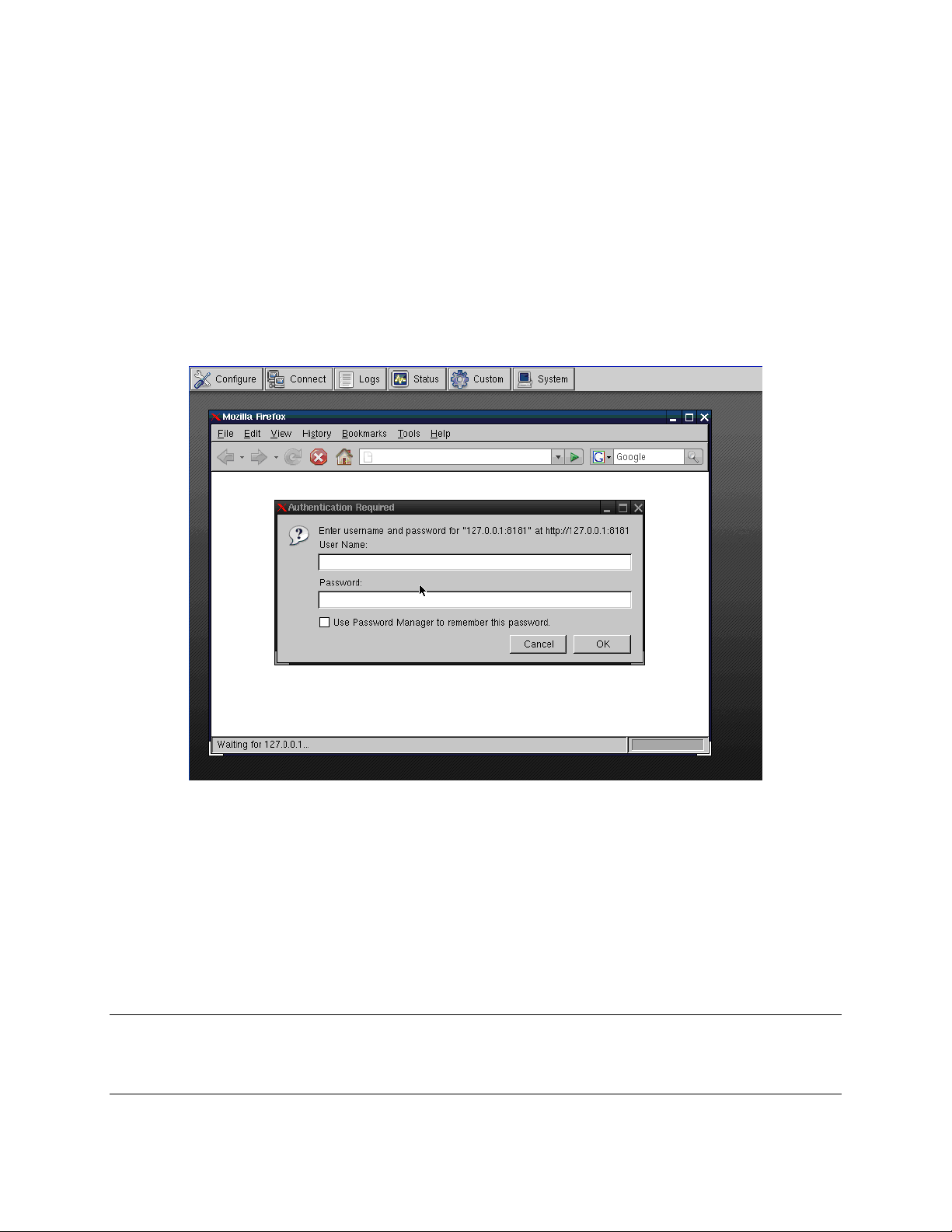
3.1.3 Initial B092-016 connection
For the initial configuration of the B092-016 Console Server, you will need to connect a console
(keyboard, mouse and display) or a KVM switch directly to its mouse, keyboard and VGA ports. When
you initially power on the B092-016, you will be prompted on your directly connected video console to
log in
Enter the default administration username and password (Username: root Password: default).
The B092-016 control panel will be displayed
Click the Configure button on the control panel. This will load the Firefox browser and open the
B092-016 Management Console
At the Management Console menu select System: Administration
3.2 Administrator Password
For security reasons, only the administration user named root can initially log into your Console Server.
Only those people who know the root password can access and reconfigure the Console Server itself.
However, anyone who correctly guesses the root password (and the default root password which is
default) could gain access. It is therefore essential that you enter and confirm a new root password
before giving the Console Server any access to, or control of, your computers and network appliances.
Note: It is also recommended that you set up a new Administrator user as soon as convenient and log-
in as this new user for all ongoing administration functions (rather than root). This Administrator can be
configured in the admin group with full access privileges through the Serial & Network: Users & Groups
menu as detailed in Chapter 4
21
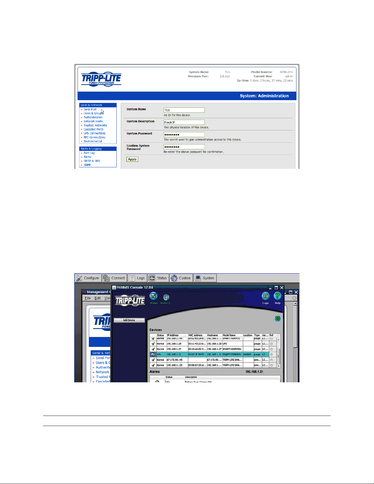
Page 22
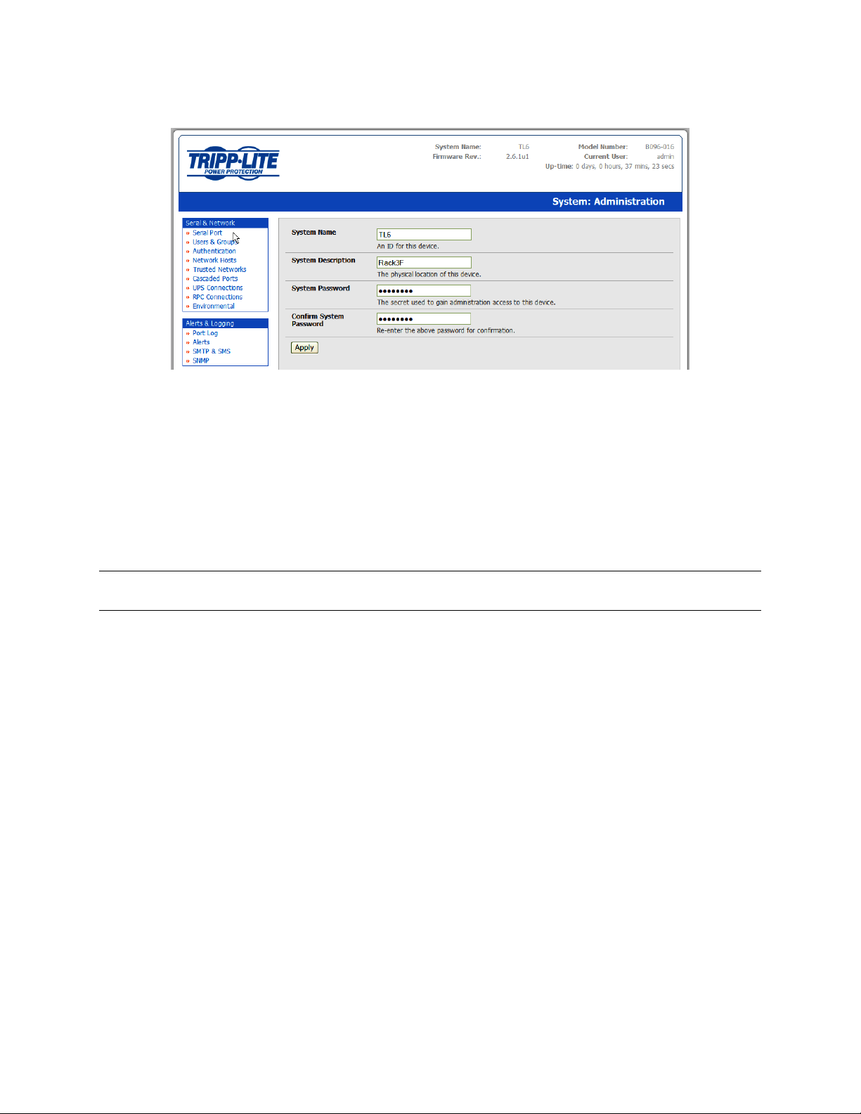
Select System: Administration
Enter a new System Password then re-enter it in Confirm System Password. This is the new
password for root, the main administrative user account, so it is important that you choose a
complex password, and keep it safe
You may now wish to enter a System Name and System Description for the Console Server to
give it a unique ID and make it simple to identify
Click Apply. As password has been changed, you will be prompted to log in again. This time use
the new password
Note If you are not confident your Console Server has been supplied with the current release of
firmware, you can upgrade. Refer to Upgrade Firmware - Chapter 10
3.3 Network IP address
It is time to enter an IP address for the principal 10/100 LAN port on the Console Server; or enable its
DHCP client so that it automatically obtains an IP address from a DHCP server on the network to which it
is to be connected.
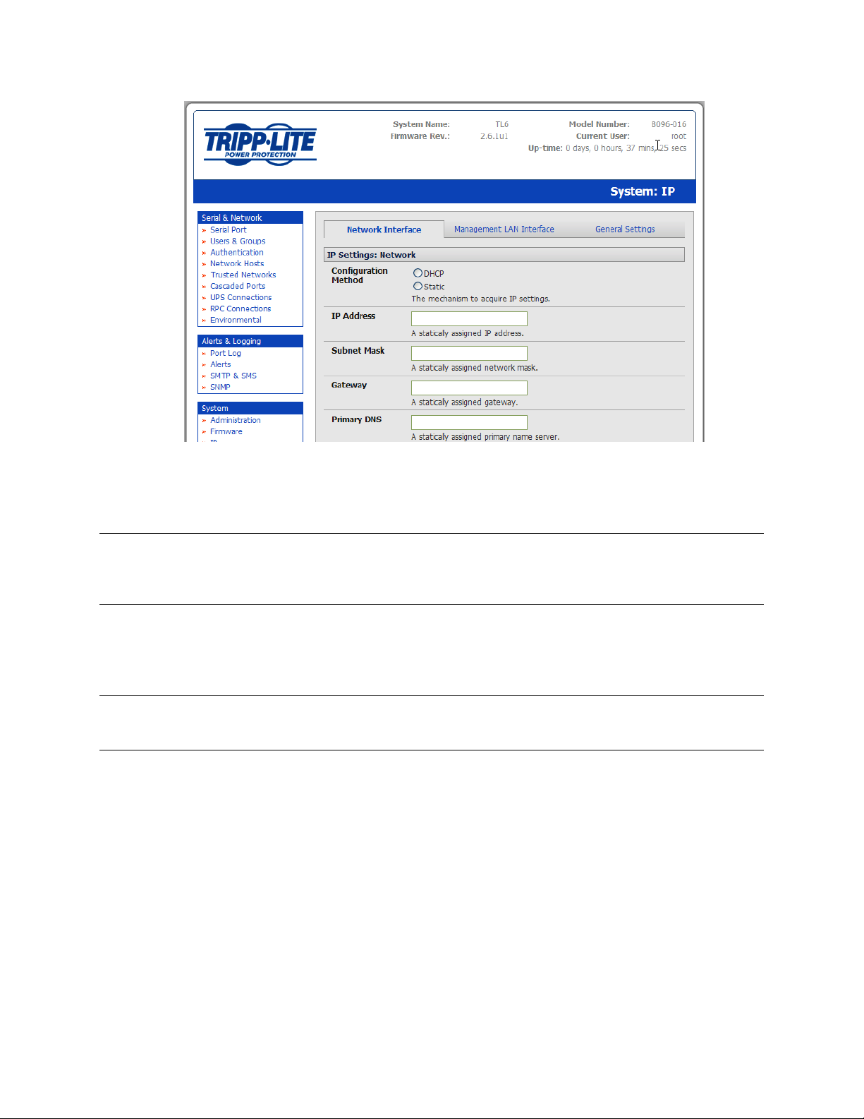
On the System: IP menu select the Network Interface page then check DHCP or static for the
Configuration Method
If you select static you must manually enter the new IP Address, Subnet Mask, Gateway and
DNS server details. This selection automatically disables the DHCP client
22
Page 23
If you select DHCP, the Console Server will look for configuration details from a DHCP server on
your management LAN. This selection automatically disables any static address. The Console
Server MAC address can be found on a label on the base plate
Note In its factory default state (with no Configuration Method selected) the Console Server has its
DHCP client enabled, so it automatically accepts any network IP address assigned by a DHCP
server on your network. In this initial state, the Console Server will then respond to both its Static
address (192.168.0.1) and its newly assigned DHCP address
By default, the Console Server 10/100 LAN port auto detects the Ethernet connection speed.
However you can use the Media menu to lock the Ethernet to 10 Mb/s or 100Mb/s and to Full
Duplex (FD) or Half Duplex (HD)
Note If you have changed the Console Server IP address, you may need to reconfigure your Computer
so it has an IP address that is in the same network range as this new address (as detailed in an
earlier note in this chapter)
Click Apply
You will need to reconnect the browser on the Computer that is connected to the Console
Server by entering http://new IP address
3.3.1 IPv6 configuration
By default, the Console Server Ethernet interfaces support IPv4, however, they can also be configured
for IPv6 operation:
On the System: IP menu select General Settings page and check Enable IPv6
23
Page 24
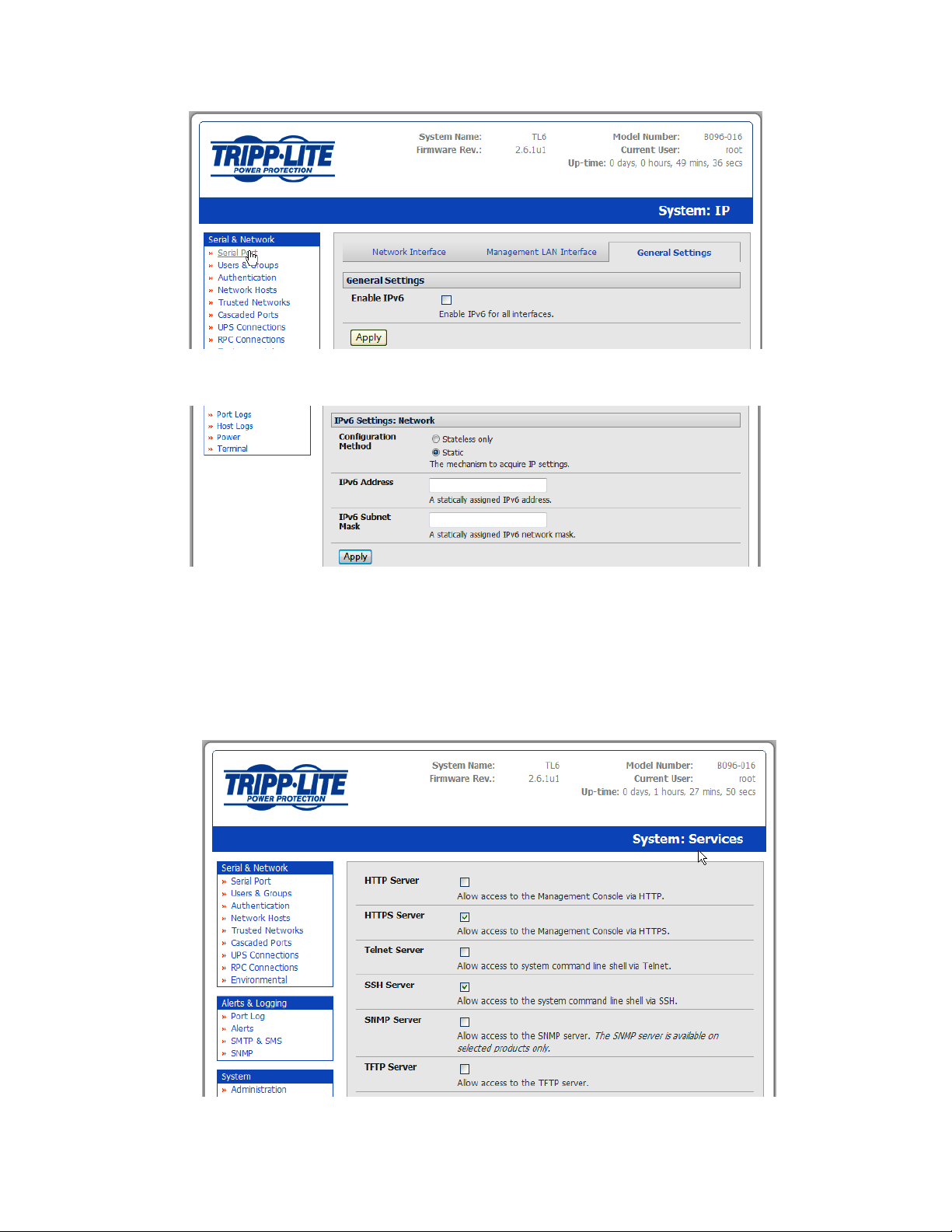
You will then need to configure the IPv6 parameters on each interface page
3.4 System Services
The Administrator has a selection of access protocols that can be used to access the Console Server. The
factory default enables HTTPS and SSH access to the Console Server and disables HTTP and Telnet. The
User can also use the nominated services for limited access to the Console Server itself. The
Administrator can configure the services to be enabled:
24
Page 25

Select System: Services. Then select /deselect the service to be enabled /disabled. The following
access protocol options are available:
HTTPS Ensures secure browser access to all the Management Console menus. It also allows
appropriately configured Users secure browser access to selected Management
Console Manage menus. If HTTPS is enabled, the Administrator will be able to use a
secure browser connection to the Console Server’s Management Console. For
information on certificate and user/client software configuration, refer to Chapter 9 -
Authentication. By default, HTTPS is enabled, and it is recommended that only HTTPS
access be used if the Console Server is to be managed over any public network (e.g.
the Internet).
HTTP Allows the Administrator basic browser access to the Management Console. It is
recommended that you disable the HTTP service if the Console Server is to be
remotely accessed over the Internet.
Telnet Gives the Administrator Telnet access to the system command line shell (Linux
commands). While this may be suitable for a local direct connection over a
management LAN, it is recommended this service be disabled if the Console Server is
to be remotely administered.
SSH Provides secure SSH access to the Linux command line shell. It is recommended you
choose SSH as the protocol when the Administrator is connecting to the Console
Server over the Internet or over any other public network. This will provide
authenticated communications between the SSH client program on the remote
Computer and the SSH sever in the Console Server. For more information on SSH
configuration, refer to Chapter 9 - Authentication.
25
Page 26

There are also a number of related service options that can be configured at this stage:
SNMP Enables netsnmp in the Console Server which will keep a remote log of all posted
information. SNMP is disabled by default. To modify the default SNMP settings, the
Administrator must make the edits at the command line as described in Chapter 15 –
Advanced Configuration
TFTP The Console Servers set up default TFTP server on the USB flash card. This server can
be used to store config files, maintain access and transaction logs, etc.
Ping Allows the Console Server to respond to incoming ICMP echo requests. Ping is
enabled by default, however, for security reasons this service should generally be
disabled post initial configuration
And there are some serial port access parameters that can be configured on this menu:
Base The Console Server uses specific default ranges for the TCP/IP ports for the various
access services that Users and Administrators can use to access devices attached to
serial ports (as covered in Chapter 4 – Configuring Serial Ports). The Administrator
can also set alternate ranges for these services, and these secondary ports will then
be used in addition to the defaults.
The default TCP/IP base port address for Telnet access is 2000, and the range for
Telnet is IP Address: Port (2000 + serial port #) i.e. 2001 – 2048. So if the
Administrator were to set 8000 as a secondary base for Telnet then serial port #2 on
the Console Server can be Telnet accessed at IP Address: 2002 and at IP Address:
8002.
The default base for SSH is 3000; for Raw TCP is 4000; for RFC2217 it is 5000 and for
Unauthenticated Telnet it is 6000.
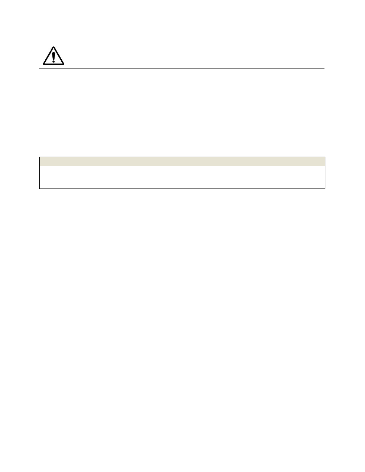
The B092-016 Console Server with PowerAlert also presents some additional service and
configuration options:
VNC The B092-016 Console Server has an internal VNC server. When enabled, it allows
remote users to connect to the Console Server and run the PowerAlert software
and any other embedded thin client programs as if they were plugged in locally to
the KVM connectors on the B092-016 (refer to Chapter 16 for more details). Users
connect using port 5900 and need to run
Secure VNC This enables a secure encrypted remote connection using VNC over SSL on port
5800 to the B092-016 Console Server (refer to Chapter 16)
PowerAlert This configuration option will automatically start the PowerAlert application on
the B092-016 and display the console as soon as you log into the local display or
VNC session (refer to Chapter 16). The complete PowerAlert manual can be
downloaded at
www.tripplite.com/EN/support/PowerAlert/Downloads.cfm
a VNC client applet
26
Page 27

Click Apply. As you apply your services selections, the screen will be updated with a
confirmation message:
Message Changes to configuration succeeded.
3.5 Communications Software
You need to configure the access protocols that the communications software on the Administrator and
User Computer will use when connecting to the Console Server (and when connecting to serial devices
and network hosts which are attached to the Console Server).
This section provides an overview of the communications software tools that can be used on the remote
computer. Tripp Lite recommends the SDT Connector software tool that is provided with the Console
Server, however, generic tools such as PuTTY and SSHTerm may also be used.
3.5.1 SDT Connector
We recommend using the SDT Connector communications software for all communications with Console
Servers. Each Console Server is supplied with an unlimited number of SDT Connector licenses to use with
that Console Server.
SDT Connector is a lightweight tool that enables Users and Administrators to securely access the Console
Server, and the various computers, network devices and appliances that may be serially or networkconnected to the Console Server.
SDT Connector can be installed on Windows 2000, XP, 2003, Vista and on most Linux, UNIX and Solaris
computers as detailed in Chapter 7.
3.5.2 PuTTY
Communications packages like PuTTY can be also used to connect to the Console Server command line
(and to connect to serially attached devices as covered in Chapter 4). PuTTY is a freeware
implementation of Telnet and SSH for Win32 and UNIX platforms. It runs as an executable application
without needing to be installed onto your system. PuTTY (the Telnet and SSH client itself) can be
downloaded at http://www.tucows.com/preview/195286.html
27
Page 28
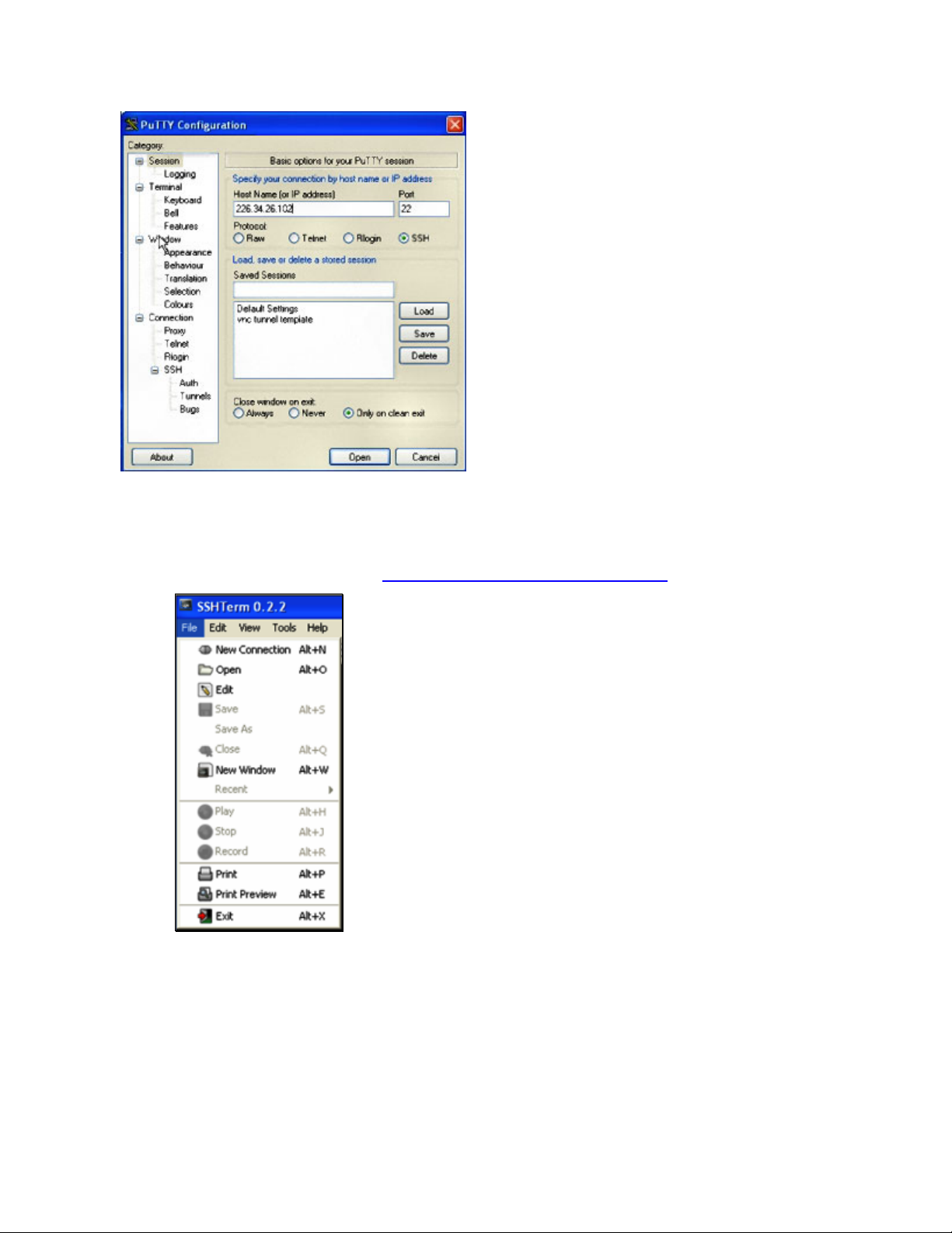
To use PuTTY for an SSH terminal session from a
Windows client, enter the Console Server’s IP
address as the ‘Host Name (or IP address)’
To access the Console Server command line,
select ‘SSH’ as the protocol and use the default
IP Port 22
Click ‘Open’ and the Console Server login
prompt will appear. (You may also receive a
‘Security Alert’ that the host’s key is not cached.
Choose ‘yes’ to continue.)
Using the Telnet protocol is similarly simple, but
you need to use the default port 23
3.5.3 SSHTerm
Another common communications package that may be useful is SSHTerm. This is an open source
package that can be downloaded from http://sourceforge.net/projects/sshtools
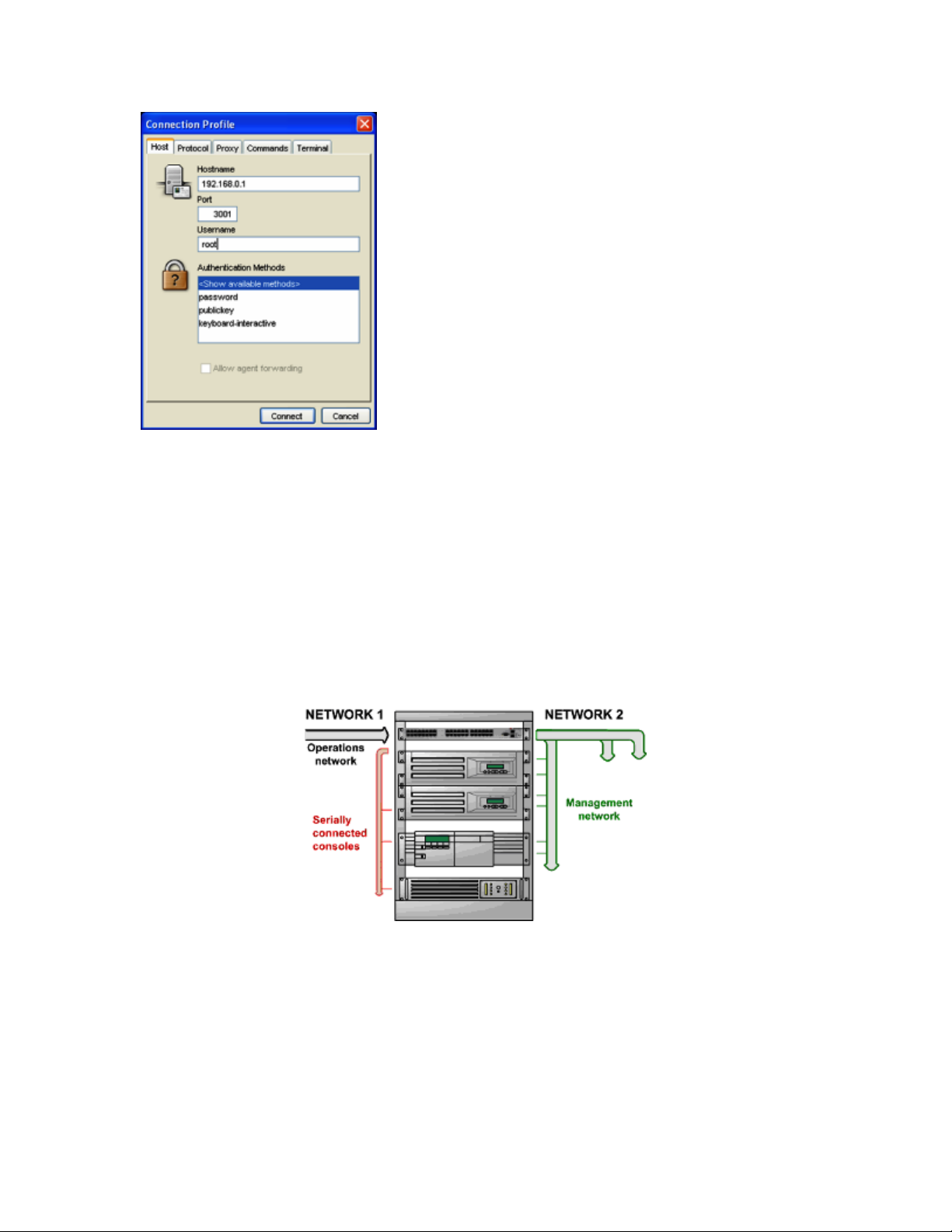
To use SSHTerm for an SSH terminal session from a
Windows Client, simply Select the ‘File’ option and click
on ‘New Connection’.
A new dialog box will appear for your ‘Connection Profile’.
Type in the host name or IP address (for the Console
Server unit) and the TCP port that the SSH session will use
(port 22). Then type in your username and choose
password authentication and click Connect.
28
Page 29
A message may appear about the host key fingerprint.
You will need to select ‘Yes’ or ‘Always’ to continue.
The next step is password authentication. You will be
prompted for your username and password from the
remote system. You will then be logged on to the Console
Server
3.6 Management Network Configuration (B096-048/016 only)
The B096-048/016 Console Server Management Switches have a second Ethernet network port that can
be configured as a management Console Server/LAN port or as a failover/OoB access port.
3.6.1 Configure Management Switch as a Management LAN gateway
The Management Switch in the B096-048/016 Console Servers can be configured to provide a
management LAN gateway. With this configuration, the B096-048/016 provides firewall, router and
DHCP server features and you can connect managed hosts to this management LAN.
These features are all disabled by default. To configure the Management LAN gateway:
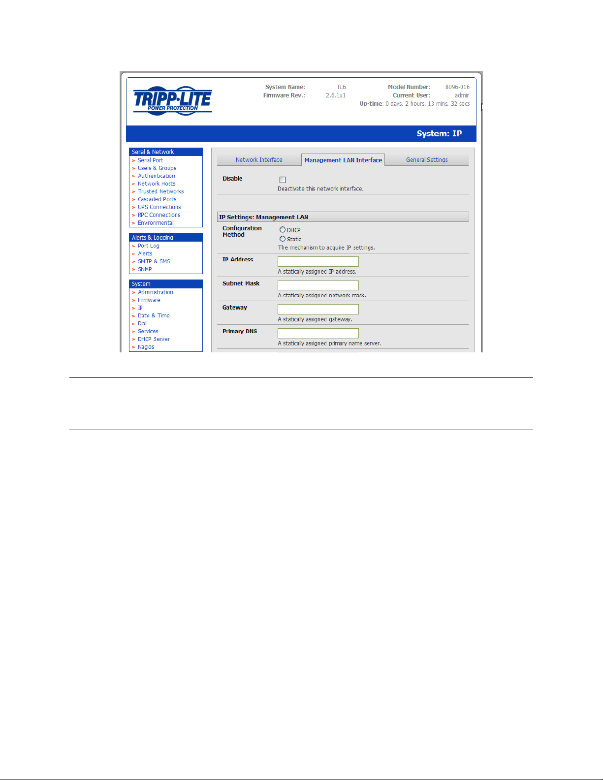
Select the Management LAN page on the System: IP menu and uncheck Disable
Configure the IP Address and Subnet Mask for the Management LAN (leaving the Gateway and
DNS fields blank) then click Apply
The management LAN gateway function is now enabled with default firewall and router rules.
These rules can be reconfigured at the command line.
29
Page 30
Note The second Ethernet port on the B096-048/016 can be configured as either a Management LAN
gateway port or it can be configured as an OoB/Failover port - but not both. So be sure that you
did not allocate Management LAN as the Failover Interface when you configured the principal
The B096-048/016 Console Server Management Switches also host a DHCP server which by default is set
at disabled. The DHCP server enables the automatic distribution of IP addresses to hosts running DHCP
clients on the Management LAN. To enable the DHCP server:
Network connection on the System: IP menu
On the System: IP menu select the Management LAN page and click the Disabled label in the
DHCP Server field; or go to the System: DHCP Server menu and check Enable DHCP Server
30
Page 31

To configure the DHCP server for the Management LAN:
Enter the Gateway address that is to be issued to the DHCP clients. If this field is left blank, the
IP address of the B096-048/016 will be used
Enter the Primary DNS and Secondary DNS address to issue the DHCP clients. Again if this field
is left blank, the IP address of the B096-048/016 is used, so leave this field blank for automatic
DNS server assignment
Optionally enter a Domain Name suffix to issue DHCP clients
Enter the Default Lease time and Maximum Lease time in seconds. The lease time is the time
that a dynamically assigned IP address is valid before the client must request it again
Click Apply
The DHCP server will sequentially issue IP addresses from a specified address pool(s):
Click Add in the Dynamic Address Allocation Pools field
Enter the DHCP Pool Start Address and End Address and click Apply
The DHCP server also supports pre-assigning IP addresses to be allocated only to specific MAC addresses
and reserving IP addresses to be used by connected hosts with fixed IP addresses. To reserve an IP
addresses for a particular host:
Click Add in the Reserved Addresses field
Enter the Hostname, the Hardware Address (MAC) and the Statically Reserved IP address for
the DHCP client and click Apply
31
Page 32

Once DHCP has initially allocated hosts addresses, it is recommended to copy these into the preassigned list so the same IP address will be reallocated in the event of a reboot.
3.6.3 Configure Management Switch for Failover or Broadband OoB
The Management Switch in the B096-048/016 Console Server can be configured to provide a failover
option. In the event of a problem using the main LAN connection for accessing the Console Server, an
alternate access path is used.
By default, the failover is not enabled. To enable, select the Network page on the System: IP
menu
Now select the Failover Interface to be used in the event of an outage on the main network.
This can be:
o an alternate broadband Ethernet connection or
o the B096-048/016 internal modem or
o an external serial modem/ISDN device connected to the B096-048/016 console port (for
out-dialing to an ISP or the remote management office)
Click Apply. You have selected the failover method. However, it is not active until you have
specified the external sites to be probed to trigger failover and set up the failover ports
themselves. This is covered in Chapter 5.
Note The second Ethernet port on the B096-048/016 can be configured as either a Management LAN
gateway port or it can be configured as an OoB/Failover port - but not both. So ensure you did
not configure this port as the Management LAN
on the System: IP menu
32
Page 33

4. SERIAL PORT AND NETWORK HOST
Introduction
The Console Server enables access and control of serially-attached devices and network-attached
devices (hosts). The Administrator must configure access privileges for each of these devices, and specify
the services that can be used to control the devices. The Administrator can also set up new users and
specify each user’s individual access and control privileges.
This chapter covers each of the steps in configuring hosts and serially attached devices:
Configure Serial Ports – setting up the protocols to be used in accessing serially-connected devices
Users & Groups – setting up users and defining the access permissions for each of these users
Authentication – covered in Chapter 9
Network Hosts – configuring access to local network connected computers or appliances (referred to as
hosts)
Configuring Trusted Networks
Cascading and Redirection of Serial Console Ports
Connecting to Power (UPS, PDU and IPMI) and Environmetal Monitoring (EMD) devices
4.1 Configuring Serial Ports
To configure a serial port you must first set the Common Settings (Chapter 4.1.1) that are to be used for
the data connection to that port (e.g. baud rate) and the mode the port is to operate in. Each port can
be set to support one of five operating modes:
i. Console Server Mode (Chapter 4.1.2) is the default setting and enables general access to the serial
console port on serially attached devices
ii. Device Mode (Chapter 4.1.3) sets the serial port up to communicate with an intelligent serial
controlled PDU, UPS or Environmental Monitor Devices (EMD)
iii. SDT Mode (Chapter 4.1.4) enables graphical console access (with RDP, VNC, HTTPS etc) to hosts that
are serially connected
iv. Terminal Server Mode (Chapter 4.1.5) sets the serial port to await an incoming terminal login
session
v. Serial Bridge Mode (Chapter 4.1.6) enables the transparent interconnection of two serial port
devices over a network
To select the serial port to configure:
Select Serial & Network: Serial Port and click Edit on the port to be reconfigured
Note If you wish to set the same protocol options for multiple serial ports at once, click Edit Multiple
Ports and select which ports you wish to configure as a group
33
Page 34

When you have configured the common settings and the mode for each port, set up any remote
syslog (Chapter 4.1.7), then click Apply
If the Console Server has been configured with distributed Nagios monitoring enabled then you
will also be presented with Nagios Settings options to enable nominated services on the Host to
be monitored (refer to Chapter 10 – Nagios Integration)
4.1.1 Common Settings
There are a number of common settings available for each serial port. These are independent of the
mode in which the port is being used. These serial port parameters must be set so they match the serial
port parameters on the device which is attached to that port:
Specify a label for the port
Select the appropriate Baud Rate, Parity, Data Bits, Stop Bits and Flow Control for each port
(and ensure they match the settings for serial device that is connected). The Signaling Protocol is
hard configured to be RS232
Note The serial ports are all set at the factory to RS232 9600 baud, no parity, 8 data bits, 1 stop bit and
Console Server Mode. The baud rate can be changed to 2400 – 230400 baud using the
management console. Lower baud rates (50, 75, 110, 134, 150, 200, 300, 600, 1200, 1800 baud)
can be configured from the command line as detailed in Chapter 14
34
Page 35

4.1.2 Console Server Mode
Select Console Server Mode to enable remote management access to the serial console that is attached
to the serial port:
Logging Level This specifies the level of information to be logged and monitored (refer to Chapter 7 -
Alerts and Logging)
35
Page 36

Telnet Check to enable Telnet access to the serial port. When enabled, a Telnet client on a User or
Administrator’s computer can connect to a serial device attached to this serial port on the
Console Server. The default port address is IP Address _ Port (2000 + serial port #) i.e. 2001 –
2048
Telnet communications are unencrypted, so this protocol is generally recommended for local
connections only. However, if the remote communications are being tunneled with SDT
Connector, then Telnet can be used to securely access these attached devices (see Note below).
With Win2000/XP/NT you can run Telnet from the command prompt (cmd.exe). Vista comes
with a Telnet client and server but they are not enabled by default. To enable Telnet, simply:
Log in as Admin and go to Start/ Control Panel/Programs and Features
Select Turn Windows Features On or Off, check the Telnet Client and click OK
Note In Console Server mode, Users and Administrators can use SDT Connector to set up secure
Telnet connections that are SSH tunneled from their client computers to the serial port on the
Console Server with a simple point-and-click.
To use SDT Connector to access consoles on the Console Server serial ports, configure the SDT
Connector with the Console Server as a gateway, then as a host. Now enable Telnet service on
Port (2000 + serial port #) i.e. 2001–2048. Refer to Chapter 6 for more details on using SDT
Connector for Telnet and SSH access to devices attached to the Console Server serial ports.
You can also use standard communications packages like PuTTY to set a direct Telnet (or SSH)
connection to the serial ports (refer Note below):
Note PuTTY also supports Telnet (and SSH). The procedure to set up a Telnet session is simple: Enter
the Console Server’s IP address as the ‘Host Name (or IP address)’. Select ‘Telnet’ as the
protocol and set the ‘TCP port’ to 2000 plus the physical serial port number (i.e. 2001 to 2048).
Click the ‘Open’ button. You may then receive a ‘Security Alert’ that the host’s key is not cached.
Choose ‘yes’ to continue. You will then be presented with the login prompt of the remote system
connected to the serial port chosen on the Console Server. You can login as normal and use the
host serial console screen.
36
Page 37

PuTTY can be downloaded at http://www.tucows.com/preview/195286.html
SSH It is recommended that the User or Administrator uses SSH as the protocol for connecting to
serial consoles attached to the Console Server when communicating over the Internet or any
other public network. This will provide an authenticated, encrypted connection between the
SSH client program on the remote user’s computer and the Console Server. The user’s
communication with the serial device attached to the Console Server is therefore secure.
It is recommended for Users and Administrators to use SDT Connector when making an SSH
connection to the consoles on devices attached to the Console Server’s serial ports.
Configure the SDT Connector with the Console Server as a gateway, then as a host, and
enable SSH service on Port (3000 + serial port #) i.e. 3001-3048 (refer to Chapter 6).
You can also use common communications packages, like PuTTY or SSHTerm to SSH connect
directly to port address IP Address _ Port (3000 + serial port #) i.e. 3001–3048.
Alternately SSH connections can be configured using the standard SSH port 22. The serial
port being accessed is then identified by appending a descriptor to the username. This syntax
supports any of:
<username>:<portXX>
<username>:<port label>
<username>:<ttySX>
<username>:<serial>
So for a user named 'fred' to access serial port 2, when setting up the SSHTerm or the PuTTY
SSH client, instead of typing username = fred and ssh port = 3002, the alternate is to type
username = fred:port02 (or username = fred:ttyS1) and ssh port = 22.
Or, by typing username=fred:serial and ssh port = 22, the user is presented with a port
selection option:
37
Page 38

This syntax enables users to set up SSH tunnels to all serial ports with only a single IP port 22
having to be opened in their firewall/gateway.
TCP RAW TCP allows connections directly to a TCP socket. Communications programs such as
PuTTY also support RAW TCP, however, this protocol would usually be used by a custom
application. For RAW TCP, the default port address is IP Address _ Port (4000 + serial port #)
i.e. 4001 – 4048.
RAW TCP also enables the serial port to be tunneled to a remote Console Server, so two
serial port devices can be transparently interconnected over a network (see Chapter 4.1.6 –
Serial Bridging).
RFC2217 Selecting RFC2217 enables serial port redirection on that port. For RFC2217, the default port
address is IP Address _ Port (5000 + serial port #) i.e. 5001 – 5048.
You will also need to run serial port redirector software on your desktop computer. This
software, which supports RFC2217 virtual com ports, is available commercially and as
freeware, for Windows UNIX and Linux, and it allows you to use a serial device connected to
the remote Console Server as if it were connected to your local serial port.
Unauthenticated Telnet Selecting Unauthenticated Telnet enables Telnet access to the serial port
without requiring the user to provide credentials. When a user accesses the Console Server
to Telnet to a serial port they are normally given a login prompt. However, with
unauthenticated Telnet, they connect directly through to port with any Console Server login
at all. This mode is mainly used when you have an external system (such as conserver)
managing user authentication and access privileges at the serial device level.
For Unauthenticated Telnet, the default port address is IP Address _ Port (6000 + serial port
#) i.e. 6001 – 6048.
Accumulation Period By default, once a connection has been established for a particular serial port
(such as a RFC2217 redirection or Telnet connection to a remote computer), then any
incoming characters on that port are forwarded over the network on a character by
character basis. The accumulation period changes this by specifying a period of time that
incoming characters will be collected before being sent as a packet over the network
Escape Character This enables you to change the character used for sending escape characters. The
default is ~.
Single Connection This setting limits the port to a single connection, so if multiple users have access
privileges for a particular port, only one user at a time can be accessing that port (i.e. port
“snooping” is not permitted).
38
Page 39

4.1.3 SDT Mode
This setting allows port forwarding of LAN protocols such as RDP, VNC, HTPP, HTTPS, SSH and Telnet
through to computers which are connected locally to the Console Server by their serial COM port.
However such port forwarding requires a PPP link to be set up over this serial port.
Refer to Chapter 6.6 - Using SDT Connector to Telnet or SSH connect to devices that are serially attached
to the Console Server for configuration details
4.1.4 Device (RPC, UPS, EMD) Mode
This mode configures the selected serial port to communicate with a serial controlled Uninterruptible
Power Supply (UPS), serial Remote Power Controller/ Power Distribution Unit (RPC) or Environmental
Monitoring Device (EMD)
Select the desired Device Type (UPS, RPC or EMD)
Proceed to the appropriate device configuration page (Serial & Network: UPS Connections, RPC
Connection or Environmental) as detailed in Chapter 8 - Power & Environmental Management)
The B092-016 Console Server also allows you to configure ports as UPS devices that PowerAlert
will manage. PowerAlert will discover the attached UPS device and auto-configure. See
www.tripplite.com/EN/support/PowerAlert/Downloads.cfm for a complete PowerAlert manual.
4.1.5 Terminal Server Mode
Select Terminal Server Mode and the Terminal Type (vt220, vt102, vt100, Linux or ANSI) to
enable a getty on the selected serial port.
39
Page 40

The getty will then configure the port and wait for a connection to be made. An active connection on a
serial device is usually indicated by the Data Carrier Detect (DCD) pin on the serial device being raised.
When a connection is detected, the getty program issues a login: prompt, and then invokes the login
program to handle the actual system login.
Note Selecting Terminal Server mode will disable Port Manager for that serial port, so data is no longer
logged for alerts etc.
4.1.6 Serial Bridging Mode
With serial bridging, the serial data on a nominated serial port on one Console Server is encapsulated
into network packets and then transported over a network to a second Console Server, where it is then
represented as serial data. So the two Console Servers effectively act as a virtual serial cable over an IP
network.
One Console Server is configured to be the Server. The Server serial port to be bridged is set in Console
Server mode with either RFC2217 or RAW enabled (as described in Chapter 4.1.2 – Console Server
Mode).
For the Client Console Server, the serial port to be bridged must be set in Bridging Mode:
Select Serial Bridging Mode and specify the IP address of the Server Console Server and the TCP
port address of the remote serial port (for RFC2217 bridging this will be 5001-5048)
By default, the bridging client will use RAW TCP so you must select RFC2217 if this is the Console
Server mode you have specified on the server Console Server
40
Page 41

You may secure the communications over the local Ethernet by enabling SSH however you will
need to generate and upload keys (refer to Chapter 14 – Advanced Configuration)
4.1.7 Syslog
In addition to built-in logging and monitoring (which can be applied to serial-attached and networkattached management accesses, as covered in Chapter 7 - Alerts and Logging), the Console Server can
also be configured to support the remote syslog protocol on a per serial port basis:
Select the Syslog Facility/Priority fields to enable logging of traffic on the selected serial port to
a syslog server; and to appropriately sort and action those logged messages (i.e. redirect them/
send alert email etc.)
For example if the computer attached to serial port 3 should never send anything out on its serial
console port, the Administrator can set the Facility for that port to local0 (local0 .. local7 are meant for
site local values), and the Priority to critical. At this priority, if the Console Server syslog server does
receive a message, it will automatically raise an alert. Refer to Chapter 7.
4.2 Add/Edit Users
The Administrator uses this menu selection to set up, edit and delete users and to define the access
permissions for each of these users.
41
Page 42

Users can be authorized to access specified Console Server serial ports and specified network-attached
hosts. These users can also be given full Administrator status (with full configuration and management
and access privileges).
To simplify user setup, they can be configured as members of Groups. There are two Groups set up by
default (admin and user).
1. Membership of the admin group provides the user with full Administrator privileges. The admin
user (referred to in this manual as Administrator) can access the Console Server using any of the
services which have been enabled in System: Services e.g. if only HTTPS has been enabled then
the Administrator can only access the Console Server using HTTPS. However, once logged in,
they can reconfigure the Console Server settings (e.g. to enabled HTTP/Telnet for future access).
They can also access any of the connected Hosts or serial port devices using any of the services
that have been enabled for these connections. However, since the Administrator can
reconfigure the access services for any Host or serial port, only trusted users should have
Administrator access.
Note: For convenience the SDT Connector “Retrieve Hosts” function retrieves and auto-configures
checked serial ports and checked hosts only, even for admin group users.
2. Membership of the user group provides the user with limited access to the Console Server and
connected Hosts and serial devices. These Users can access only the Management section of the
Management Console menu and they have no command line access to the Console Server. They
also can only access those Hosts and serial devices that have been checked for them, using
services that have been enabled.
3. The Administrator can also set up additional Groups with specific serial port and host access
permissions (same as Users). However users in these additional groups don’t have any access to
the Management Console menu nor to any command line access to the Console Server itself.
Lastly the Administrator can also set up users who are not a member of any Groups and they will
have the same access as users in the additional groups.
To set up new users and classify them as members of particular Groups:
42
Page 43

Select Serial & Network: Users & Groups to display the configured Groups and Users
Click Add Group to add a new Group
Add a Group name and Description for each new Group, then nominate Accessible Hosts and
Accessible Ports to specify the serial ports and hosts you wish any users in this new Group to be
able to access
Click Apply
Select Serial & Network: Users to display the configured users
Click Add User to add a new user
43
Page 44

Add a Username and a confirmed Password for each new User. You may also include
information related to the user (e.g. contact details) in the Description field
Nominate Accessible Hosts and Accessible Ports to specify which serial ports and which LAN
connected hosts you wish the user to have access to
Specify which Group (or Groups) you wish the user to be a member of.
Click Apply
Your new user will now be able to access the nominated network devices and the devices attached to
the nominated serial ports.
Note There are no specific limits on the number of users you can set up; nor on the number of users
per serial port or host. Multiple users (Users and Administrators) can control/monitor one port or
host. Similarly there are no specific limits on the number of Groups and each user can be a
member of a number of Groups (in which case they take on the cumulative access privileges of
each of those Groups). A user does not have to be a member of any Groups (but if the User is
not even a member of the default user group then they will not be able to use the Management
Console to manage ports).
Note that while there are no specific limits, the time to re-configure does increase as the number
and complexity increases so we recommend the aggregate number if users and groups be kept
under 250 (or 1000 for B092-016)
The Administrator can also edit the access settings for any existing users:
Select Serial & Network: Users & Groups and click Edit for the User to be modified
4.3 Authentication
Refer to Chapter 9.1 - Remote Authentication Configuration for authentication configuration details
4.4 Network Hosts
To access a locally networked computer or appliances (referred to as a Host), you must identify the
network connected Host; and then specify the TCP or UDP ports/services that are permitted to be used
for communicating to that Host:
44
Page 45

Selecting Serial & Network: Network Hosts presents all the network connected Hosts that have
been enabled for access, and the related access TCP ports/services
Click Add Host to enable access to a new Host (or select Edit to update the settings for existing
Host)
Enter the IP Address or DNS Name of the new network connected Host (and optionally enter a
Description)
Add or edit the Permitted Services (or TCP/UDP port numbers) that are authorized to be used in
controlling this host. Only these permitted services will be port forwarded through to the Host.
All other services (TCP/UDP ports) will be blocked.
If the Console Server has been configured with distributed Nagios monitoring enabled then you
will also be presented with Nagios Settings options to enable nominated services on the Host to
be monitored (refer to Chapter 10 – Nagios Integration)
The Logging Level specifies the level of information to be logged and monitored for each Host
access (refer to Chapter 7 - Alerts and Logging)
If the Host is a networked server with IPMI power control, then the Administrator can enable
users (Users and Administrators) to remotely cycle power and reboot (refer to Chapter 8.2 -
Configuring IPMI Power Management)
Click Apply
45
Page 46

4.5 Trusted Networks
The Trusted Networks facility gives you the option to nominate specific IP addresses that users
(Administrators and Users) must be located at in order to have access to Console Server serial ports:
Select Serial & Network: Trusted Networks
To add a new trusted network, select Add Rule
Select the Accessible Port(s) that the new rule is to be applied to
Then enter the Network Address of the subnet to be permitted access
Then specify the range of addresses that are to be permitted by entering a Network Mask for
that permitted IP range e.g.
To permit all the users located with a particular Class C network (204.15.5.0 say) connection
to the nominated port, add the following Trusted Network New Rule:
Network IP Address 204.15.5.0
Subnet Mask 255.255.255.0
If you want to permit only the one user who is located at a specific IP address (204.15.5.13
say) to connect:
46
Page 47

Network IP Address 204.15.5.0
Subnet Mask 255.255.255.255
If however you want to allow all the users operating from within a specific range of IP
addresses (say any of the thirty addresses from 204.15.5.129 to 204.15.5.158) to be
permitted connection to the nominated port:
Host /Subnet Address 204.15.5.128
Subnet Mask 255.255.255.224
Click Apply
Note The above Trusted Networks will limit access by Users and the Administrator to the console serial
ports. However they do not restrict access by the Administrator to the Console Server itself or to
attached hosts. To change the default settings for this access, you will to need to edit the IPtables
rules as described in the Chapter 14 - Advanced.
4.6 Serial Port Cascading
Cascaded Ports enables you to cluster distributed Console Servers so that a large number of serial ports
(up to 1000) can be configured and accessed through one IP address and managed through the one
Management Console. One Console Server, the Master, controls other Console Servers as Slave units
and all the serial ports on the Slave units appear as if they are part of the Master.
Each Slave connects to the Master with an SSH connection using public key authentication. So the
Master accesses each Slave using an SSH key pair, rather than using passwords, ensuring secure
authenticated communications. So the Slave Console Server units can be distributed locally on a LAN or
remotely over public networks around the world.
4.6.1 Automatically generate and upload SSH keys
To set up public key authentication, you must first generate an RSA or DSA key pair and upload them
into the Master and Slave Console Servers. This can all be done automatically from the Master:
Select System: Administration on Master’s Management Console
Check Generate SSH keys automatically and click Apply
47
Page 48

Now select whether to generate the keys using RSA and/or DSA (if unsure, select only RSA). Generating
each set of keys will require approximately two minutes and the new keys will destroy any old keys of
that type that may previously been uploaded. Also while the new generation is under way on the
master, functions relying on SSH keys (e.g. cascading) may stop functioning until they are updated with
the new set of keys. To generate keys:
Select RSA Keys and/or DSA Keys
Click Apply
Once the new keys have been successfully generated simply Click here to return and the
keys will automatically be uploaded to the Master and connected Salves
4.6.2 Manually generate and upload SSH keys
Alternately if you have a RSA or DSA key pair, you can manually upload them to the Master and Slave
Console Servers.
Note If you do not already have an RSA or DSA key pair and you do not wish to use it, you will need to
create a key pair using ssh-keygen, PuTTYgen or a similar tool as detailed in Chapter 15.6
To manually upload the key public and private key pair to the Master Console Server:
Select System: Administration on Master’s Management Console
Browse to the location you have stored RSA (or DSA) Public Key and upload it to SSH RSA (DSA)
Public Key
Browse to the stored RSA (or DSA) Private Key and upload it to SSH RSA (DSA) Private Key
Click Apply
48
Page 49

Next, you must register the Public Key as an Authorized Key on the Slave. In the simple case with only
one Master with multiple Slaves, you need only upload the one RSA or DSA public key for each Slave.
Note The use of key pairs can be confusing because in many cases one file (Public Key) fulfills two
roles – Public Key and Authorized Key. For a more detailed explanation, refer to the Authorized
Keys section of Chapter 15. Also refer to this chapter if you need to use more than one set of
Authorized Keys in the Slave
Select System: Administration on the Slave’s Management Console
Browse again to the stored RSA (or DSA) Public Key and upload it to Slave’s SSH Authorized Key
Click Apply
The next step is to Fingerprint each new Slave-Master connection. This once-off step will validate that
you are establishing an SSH session with the correct target. On the first connection the Slave will receive
a fingerprint from the Master which will be used on all future connections:
To establish the fingerprint, first log in the Master server as root and establish an SSH
connection to the Slave remote host:
# ssh remhost
Once the SSH connection has been established, you will be asked to accept the key. Answer yes and the
fingerprint will be added to the list of known hosts. For more details on Fingerprinting, refer to Chapter
15.6
If you are asked to supply a password, then there has been a problem with uploading keys. The
keys should remove any need to supply a password.
49
Page 50

4.6.3 Configure the Slaves and their serial ports
You can now begin setting up the Slaves and configuring Slave serial ports from the Master Console
Server:
Select Serial & Network: Cascaded Ports on the Master’s Management Console
To add clustering support select Add Slave
Note You will be prevented from adding any Slaves until you have automatically or manually generated
SSH keys:
To define and configure a Slave:
Enter the remote IP Address (or DNS Name) for the Slave Console Server
Enter a brief Description and a short Label for the Slave (use a convention that enables effective
management of large networks of clustered Console Servers and the connected devices)
Enter the full number of serial ports on the Slave unit in Number of Ports
Click Apply. This will establish the SSH tunnel between the Master and the new Slave
The Serial & Network: Cascaded Ports menu displays all the Slaves and the port numbers that have
been allocated on the Master. If the Master Console Server has 16 ports of its own, then ports 1-16 are
pre-allocated to the Master. So the first Slave added will be assigned port number 17 and onwards.
Once you have added all the Slave Console Servers, the Slave serial ports and the connected devices are
configurable and accessible from the Master’s Management Console menu, and accessible through the
Master’s IP address.
Select the appropriate Serial & Network: Serial Port and Edit to configure the serial ports on the
Slave
Select the appropriate Serial & Network: Users & Groups to add new users with access
privileges to the Slave serial ports (or to extend existing users access privileges)
Select the appropriate Serial & Network: Trusted Networks to specify network addresses that
can access nominated Slave serial ports
Select the appropriate Alerts & Logging: Alerts to configure Slave port Connection, State Change
or Pattern Match alerts
The configuration changes made on the Master are propagated out to all the Slaves when you
click Apply.
50
Page 51

4.6.4 Managing the Slaves
The Master is in control of the Slave serial ports. So, for example, if you change a User’s access privileges
or edit any serial port setting on the Master, the updated configuration files will be sent out to each
Slave in parallel. Each Slave will then automatically make changes to their local configurations (and only
make those changes that relate to its particular serial ports).
You can still use the local Slave Management Console to change the settings on any Slave serial port
(such as to alter the baud rates). However these changes will be overwritten next time the Master sends
out a configuration file update.
Also while the Master is in control of all Slave serial port related functions, it is not master over the Slave
network host connections or over the Slave Console Server system itself.
So Slave functions such as IP, SMTP & SNMP Settings, Date &Time, DHCP server must be managed by
accessing each Slave directly and these functions are not overwritten when configuration changes are
propagated from the Master. Similarly, the Slave’s Network Host and IPMI settings have to be
configured at each Slave.
Also, the Master’s Management Console provides a consolidated view of the settings for its own and all
the Slave’s serial ports. However, the Master does not provide a fully consolidated view. For example, if
you want to find out who is logged in to cascaded serial ports from the Master, you’ll see that Status:
Active Users only displays those users active on the Master’s ports, so you may need to write custom
scripts to provide this view. This is covered in Chapter 11.
51
Page 52

5. FAILOVER AND OUT-OF-BAND ACCESS
Introduction
The Console Server has a number of failover and out-of-band access capabilities to ensure availability in
the event there are difficulties in accessing the Console Server through the principal network path. This
chapter covers:
Out-of-band (OoB) access from a remote location using dial-up modem
Out-dial failover
OoB access using an alternate broadband link (B096-048/016 models only)
Broadband failover
5.1 OoB Dial-In Access
To enable OoB dial-in access, first set up the Console Server configuration for dial-in PPP access. Once
the Console Server is so configured, it will wait for an incoming connection from a dial-in at a remote
site.
Then remote Administrator’s must be configured to dial-in and must establish a network connection to
the Console Server.
Note The B096-048/016 Console Servers have an internal modem for dial-up OoB access. The B092-
016 Console Servers need an external modem to be attached via a serial cable to their DB9 port.
5.1.1 Configure dial-in PPP
To enable dial-in PPP access on the Console Server modem port/ internal modem:
52
Page 53

Select the System: Dial menu option and the port to be configured (Serial DB9 Port or Internal
Modem Port)
Note The Console Server’s console/modem serial port is set by default to 115200 baud, No parity, 8
data bits and 1 stop bit, with software (Xon-Xoff) flow control enabled. You can modify the baud
rate and flow control using the Management Console. You can further configure the
console/modem port settings by editing /etc/mgetty.config files as described in Chapter 14.
Select the Baud Rate and Flow Control that will communicate with the modem
Check the Enable Dial-In Access box
Enter the User name and Password to be used for the dial-in PPP link
In the Remote Address field, enter the IP address to be assigned to the dial-in client. You can
select any address for the Remote IP Address. However, it and the Local IP Address must both
be in the same network range (e.g. 200.100.1.12 and 200.100.1.67)
In the Local Address field, enter the IP address for the Dial-In PPP Server. This is the IP address
that will be used by the remote client to access Console Server once the modem connection is
53
Page 54

established. Again, you can select any address for the Local IP Address but both must be in the
same network range as the Remote IP Address
The Default Route option enables the dialed PPP connection to become the default route for
the Console Server
The Custom Modem Initialization option allows a custom AT string modem initialization string
to be entered (e.g. AT&C1&D3&K3)
Then select the Authentication Type to be applied to the dial-in connection. The Console Server
uses authentication to challenge Administrators who dial-in to the Console Server. (For dial-in
access, the username and password received from the dial-in client are verified against the local
authentication database stored on the Console Server). The Administrator must also have their
client computer configured to use the selected authentication scheme. Select PAP CHAP
MSCHAPv2 or None and click Apply
None With this selection, no username or password authentication is required for
dial-in access. This is not recommended.
PAP Password Authentication Protocol (PAP) is the usual method of user
authentication used on the internet: sending a username and password to a
server where they are compared with a table of authorized users. Whilst most
common, PAP is the least secure of the authentication options.
CHAP Challenge-Handshake Authentication Protocol (CHAP) is used to verify a user's
name and password for PPP Internet connections. It is more secure than PAP,
the other main authentication protocol.
MSCHAPv2 Microsoft Challenge Handshake Authentication Protocol (MSCHAP) is
authentication for PPP connections between a computer using a Microsoft
Windows operating system and a network access server. It is more secure than
PAP or CHAP, and is the only option that also supports data encryption
Console Servers all support dial-back for additional security. Check the Enable Dial-Back box and
enter the phone number to be called to re-establish an OoB link once a dial-in connection has
been logged
5.1.2 Using SDT Connector client for dial-in
Administrators can use their SDT Connector client to set up secure OoB dial-in access to all their remote
Console Servers. With a point and click you can initiate a dial-up connection. Refer to Chapter 6.5.
5.1.3 Set up Windows XP/ 2003/Vista client for dial-in
Open Network Connections in Control Panel and click the
New Connection Wizard
54
Page 55

Select Connect to the Internet and click Next
On the Getting Ready screen select Set Up My Connection Manually and click Next
On the Internet Connection screen select Connect Using a Dial-Up Modem and click Next
Enter a Connection Name (any name you choose) and the dial-up Phone Number that will
connect thru to the Console Server modem
Enter the PPP User Name and Password for have set up for the Console Server
5.1.4 Set up earlier Windows clients for dial-in
For Windows 2000, the PPP client set up procedure is the same as above, except you get to the
Dial-Up Networking Folder by clicking the Start button and selecting Settings. Then click
Network and Dial-up Connections and click Make New Connection
Similarly, for Windows 98, you double-click My Computer on the Desktop, then open Dial-Up
Networking and double click Make New Connection and proceed as above
55
Page 56

5.1.5 Set up Linux clients for dial-in
The online tutorial http://www.yolinux.com/TUTORIALS/LinuxTutorialPPP.html
presents a selection of
methods for establishing a dial up PPP connection:
- Command line PPP and manual configuration (which works with any Linux distribution)
- Using the Linuxconf configuration tool
(for Red Hat compatible distributions). This configures
the scripts ifup/ifdown to start and stop a PPP connection
- Using the Gnome control panel configuration tool
- WVDIAL and the Redhat "Dialup configuration tool"
- GUI dial program X-isp. Download/Installation/Configuration
For all PPP clients:
Note
Set the PPP link up with TCP/IP as the only protocol enabled
Specify that the Server will assign IP address and do DNS
Do not set up the Console Server PPP link as the default for Internet connection
-
5.2 OoB Broadband Access (B096-048/016 only)
The B096-048/016 Console Server Management Switch has a second Ethernet network port that can be
configured for alternate and OoB (out-of-band) broadband access. With two active broadband access
paths to the Console Server, in the event you are unable to access through the primary management
network, you may still have access through the alternate broadband path (e.g. a T1 link):
On the System: IP menu, select Management LAN Interface and configure the IP Address,
Subnet Mask, Gateway and DNS with the access settings that relate to the alternate link
Ensure that when configuring the principal Network Interface connection, you set the Failover
Interface to None
5.3 Broadband Ethernet Failover (B096-048/016 only)
The second Ethernet port on the B096-048/016 Console Server Management Switch can also be
configured for failover to ensure transparent high availability.
56
Page 57

When configuring the principal network connection on the System: IP Network Interface menu,
select Management LAN (eth1) as the Failover Interface to be used when a fault has been detected
with main Network Interface (eth0)
Specify the Probe Addresses of two sites (the Primary and Secondary) that the B096-048/016 is to
ping to determine if Network (eth0) is still operational
57
Page 58

Then configure Management LAN Interface (eth1) with the same IP setting that you used for the
main Network Interface (eth0) to ensure transparent redundancy
In this mode, Network 2 (eth1) is available as the transparent back-up port to Network 1 (eth0) for
accessing the management network. Network 2 will automatically and transparently take over the work
of Network 1 if for any reason Network 1 becomes unavailable. And when Network 1 becomes available
again, it takes over the work again.
5.4 Dial-Out Failover
The Console Servers can be configured so a dial-out PPP connection is automatically set up in the event
of a disruption in the principal management network:
When configuring the principal network connection in System: IP, specify Internal Modem (or the
Dial Serial DB9 if using an external modem on the Console port) as the Failover Interface to be used
when a fault has been detected with Network1 (eth0)
Specify the Probe Addresses of two sites (the Primary and Secondary) that the Console Server is to
ping to determine if Network1 is still operational
Select the System: Dial menu option and the port to be configured (Serial DB9 Port or Internal
Modem Port)
Select the Baud Rate and Flow Control that will communicate with the modem
Note You can further configure the console/modem port (e.g. to include modem init strings) by editing
/etc/mgetty.config files as described in Chapter 13.
Check the Enable Dial-Out Access box and enter the access details for the remote PPP
server to be called
58
Page 59

59
Page 60

6. SECURE TUNNELING AND SDT CONNECTOR
Introduction
Each Console Server has an embedded SSH server and uses SSH tunneling. This enables one Console
Server to securely manage all the systems and network devices in the data center, using text-based
console tools (such as SSH, Telnet, SoL) or graphical desktop tools (VNC, RDP, HTTPS, HTTP, X11,
VMware, DRAC, iLO etc).
To set up Secure Tunnel access, the computer being accessed can be located on the same local network
as the Console Server, or attached to the Console Server via its serial COM port. The remote
User/Administrator then connects to the Console Server through an SSH tunnel (via dial-up, wireless or
ISDN modem); a broadband Internet connection; an enterprise VPN network or a local network.
-
To set up the secure SSH tunnel from the Client computer to the Console Server, you must install and
launch SSH client software on the User/Administrator’s computer. It is recommended that you use the
SDT Connector client software supplied with the Console Server to do this. SDT Connector is simple to
install and it auto-configures. It provides all your users with point-and-click access to all the systems and
devices in the secure network. With one click, SDT Connector sets up a secure SSH tunnel from the client
to the selected Console Server and then establishes a port forward connection to the target network
connected host or serial connected device. It will then execute the client application that will be used in
communicating with the host.
This chapter details the basic SDT Connector operations:
Configuring the Console Server for SSH tunneled access to network attached hosts and setting
up permitted Services and Users access (Section 6.1)
Setting up the SDT Connector client with gateway, host, service and client application details
and making connections between the Client computer and hosts connected to the Console
Server (Section 6.2)
Using SDT Connector to browser access the Management Console (Section 6.3)
60
Page 61

Using SDT Connector to Telnet or SSH connect to devices that are serially attached to the
Console Server (Section 6.4)
The chapter then covers more advanced SDT Connector and SDT tunneling topics:
Using SDT Connector for out of band access (Section 6.5)
Automatic importing and exporting of configurations (Section 6.6)
Configuring Public Key Authentication (Section 6.7)
Setting up a SDT Secure Tunnel for Remote Desktop (Section 6.8)
Setting up a SDT Secure Tunnel for VNC (Section 6.9)
Using SDT to IP connect to hosts that are serially attached to the Console Server (Section 6.10)
6.1 Configuring for SDT Tunneling to Hosts
To set up the Console Server to SDT access a network attached host, the host and the permitted services
that are to be used in accessing that host need to be configured on the gateway, and User access
privileges need to be specified:
Add the new host and the permitted services using the Serial & Network: Network Hosts menu
as detailed in Network Hosts (Chapter 4.4). Only these permitted services will be forwarded by
SDT to the host. All other services (TCP/UDP ports) will be blocked.
Note Following are some of the TCP Ports used by SDT in the Console Server:
22 SSH (All SDT Tunneled connections)
23 Telnet on local LAN (forwarded inside tunnel)
80 HTTP on local LAN (forwarded inside tunnel)
3389 RDP on local LAN (forwarded inside tunnel)
5900 VNC on local LAN (forwarded inside tunnel)
73XX RDP over serial from local LAN – where XX is the serial port number (i.e. 7301to 7348)
79XX VNC over serial from local LAN – where XX is the serial port number
Add the new Users using Serial & Network: Users & Groups menu as detailed in
Network Hosts (Chapter 4.4). Users can be authorized to access the Console Server ports
and specified network-attached hosts. To simplify configuration, the Administrator can
first set up Groups with group access permissions, then Users can be classified as
members of particular Groups.
6.2 SDT Connector Configuration
The SDT Connector client works with all Console Servers. Each of these remote Console Servers has an
embedded OpenSSH based server. This server can be configured to port forward connections from the
SDT Connector client to hosts on their local network, as detailed in the previous chapter. The SDT
Connector can also be pre-configured with the access tools and applications that will be available when
access to a particular host has been established.
61
Page 62

SDT Connector can connect to the Console Server using an alternate OoB access. It can also be
configured to access the Console Server itself and to access devices connected to serial ports on the
Console Server.
6.2.1 SDT Connector client installation
The SDT Connector set up program (SDTConnector Setup-1.n.exe or sdtcon-1.n.tar.gz) is
included on the CD supplied with your Console Server
Run the set-up program:
Note For Windows clients, the SDTConnectorSetup-1.n.exe application will install the SDT Connector
1.n.exe and the config file defaults.xml. If a config file already exists on the Windows computer,
then it will not be overwritten. To remove an earlier config file, run the regedit command, search
for “SDT Connector” and then remove the directory with this name.
For Linux and other Unix clients, SDTConnector.tar.gz application will install the sdtcon-1.n.jar
and the config file defaults.xml
Once the installer completes, you will have a working SDT Connector client installed on your machine
and an icon on your desktop:
Click the SDT Connector icon on your desktop to start the client
Note SDT Connector is a Java application so it must have a Java Runtime Environment (JRE)
installed. This can be freely downloaded from http://java.sun.com/j2se/ . It will install on
Windows 2000, XP, 2003, Vista computers and on most Linux platforms. Solaris platforms are
also supported however they must have Firefox installed. SDT Connector can run on any
system with Java 1.4.2 and above installed, but it assumes the web browser is Firefox, and that
xterm -e Telnet opens a Telnet window
62
Page 63

To operate SDT Connector, add the new gateways to the client software by entering the access details
for each Console Server (refer to Section 6.2.2). Then let the client auto-configure with all host and serial
port connections from each Console Server (refer Section 6.2.3). Now point-and-click to connect to the
Hosts and serial devices (refer to Section 6.2.4)
Alternately you can manually add network connected hosts (refer Section 6.2.5) as well as manually
configure new services to be used when accessing the Console Server and the hosts (refer Section 6.2.6).
Manually configure clients to run on the computer that will use the service to connect to the hosts and
serial port devices (refer to Section 6.2.7 and 6.2.9). SDT Connector can also be set up to make an out-of-
band connection to the Console Server (refer to Section 6.2.9)
6.2.2 Configuring a new gateway in the SDT Connector client
To create a secure SSH tunnel to a new Console Server:
Click the New Gateway
icon or select the File: New Gateway menu option
Enter the IP or DNS Address of the Console Server and the SSH port that will be used (typically
22)
Note If SDT Connector is connecting to a remote Console Server through the public Internet or routed
network, you will need to:
Determine the public IP address of the Console Server (or of the router/ firewall that connects
the Console Server to the Internet) as assigned by the ISP. One way to find the public IP
address is to access http://checkip.dyndns.org/
computer on the same network as the Console Server and note the reported IP address
or http://www.whatismyip.com/ from a
Set port forwarding for TCP port 22 through any firewall/NAT/router that is located between
SDT Connector and the Console Server so that it points to the Console Server.
http://www.portforward.com
can use the Open Port Check tool from http://www.canyouseeme.org
forwarding through local firewall/NAT/router devices has been properly configured
has port forwarding instructions for a range of routers. Also you
to check if port
Enter the Username and Password of a user on the gateway that has been enabled to connect
via SSH and/or create SSH port redirections
63
Page 64

Optionally, you can enter a Descriptive Name to display instead of the IP or DNS address, and
any Notes or a Description of this gateway (such as its firmware version, site location or
anything special about its network configuration).
Click OK and an icon for the new gateway will now appear in the SDT Connector home page
Note
For an SDT Connector user to access a Console Server (and then access specific hosts or serial
devices connected to that Console Server), that user must first be set up on the Console Server,
and must be authorized to access the specific ports / hosts (refer to Chapter 5). Only these
permitted services will be forwarded through by SDT to the Host. All other services (TCP/UDP
ports) will be blocked.
6.2.3 Auto-configure SDT Connector client with the user’s access privileges
Each user on the Console Server has an access profile. This has been configured with the specific
connected hosts and serial port devices the user has authority to access, and a specific set of the
enabled services for each of them. This configuration can be auto-uploaded into the SDT Connector
client:
Click on the new gateway icon and select Retrieve Hosts. This will:
64
Page 65

configure access to network-connected Hosts that the user is authorized to access
and set up (for each of these Hosts) the services (e.g. HTTPS, IPMI2.0) and the
related IP ports being redirected
configure access to the Console Server itself (this is shown as a Local Services host)
configure access with the enabled services for the serial port devices connected to
the Console Server
Note The Retrieve Hosts function will auto-configure all classes of user (i.e. they can be members of
user or admin or some other group or no group). SDT Connector will, however, not autoconfigure the root (and it is recommended that this account is only used for initial config and for
adding an initial admin account to the Console Server)
6.2.4 Make an SDT connection through the gateway to a host
Simply point at the host to be accessed and click on the service to be used in accessing that
host. The SSH tunnel to the gateway is then automatically established, the appropriate ports
redirected through to the host, and the appropriate local client application is launched pointing
at the local endpoint of the redirection:
65
Page 66

Note The SDT Connector client can be configured with an unlimited number of Gateways. Each
Gateway can be configured to port forward to an unlimited number of locally networked Hosts.
Similarly there is no limit on the number of SDT Connector clients who can be configured to
access the one Gateway. There are also no limits on the number of Host connections that an
SDT Connector client can concurrently have open through the one Gateway tunnel.
However, there is a limit on the number of SDT Connector SSH tunnels that can be open at one
time on a particular Gateway. The B096-016 / B096-048 Console Server Management Switch
and B092-016 Console Server with PowerAlert each support at least 50 such concurrent
connections. So for a site with a B096-016 gateway you can have, at any time, up to 50 users
securely controlling an unlimited number of network attached computers, power devices and
other appliances (routers, etc) at that site.
6.2.5 Manually adding hosts to the SDT Connector gateway
For each gateway, you can manually specify the network connected hosts that will be accessed through
that Console Server; and for each host, specify the services that will used in communicating with the
host
Select the newly added gateway and click the Host icon
to create a host that will be
accessible via this gateway. (Alternatively select File: New Host)
Enter the IP or DNS Host Address of the host (if this is a DNS address, it must be resolvable by
the gateway)
Select which Services are to be used when accessing the new host. A range of service options
are pre-configured in the default SDT Connector client (RDP, VNC, HTTP, HTTPS, Dell RAC,
VMWare etc). However if you wish to add new services to the range then proceed to the next
section (Adding a new service) then return here
Optionally, you can enter a Descriptive Name for the host to be displayed instead of the IP or
DNS address, as well as any Notes or a Description of this host (such as its operating
system/release, or anything special about its configuration)
Click OK
66
Page 67

6.2.6 Manually adding new services to the new hosts
To extend the range of services that can be used when accessing hosts with SDT Connector:
Select Edit: Preferences and click the Services tab. Click Add
Enter a Service Name and click Add
Under the General tab, enter the TCP Port that this service runs on (e.g. 80 for HTTP).
Optionally, select the client to be used to access the local endpoint of the redirection
Select which Client application is associated with the new service. A range of client application
options are pre-configured in the default SDT Connector (RDP client, VNC client, HTTP browser,
HTTPS browser, Telnet client etc). However if you wish to add new client applications to this
range, then proceed to the next section (Adding a new client) and then return here
Click OK, then Close
A service typically consists of a single SSH port redirection and a local client to access it. However it may
consist of several redirections; some or all of which may have clients associated with them.
An example is the Dell RAC service. The first redirection is for the HTTPS connection to the RAC server: it
has a client associated with it (web browser) that is launched immediately upon clicking the button for
this service.
67
Page 68

The second redirection is for the VNC service that the user may choose to launch later from the RAC web
console. It automatically loads in a Java client served through the web browser, so it does not need a
local client associated with it.
On the Add Service screen, you can click Add as many times as needed to add multiple new port
redirections and associated clients
You may also specify Advanced port redirection options:
Enter the local address to bind to when creating the local endpoint of the redirection. It is not
usually necessary to change this from "localhost".
Enter a local TCP port to bind to when creating the local endpoint of the redirection. If this is left
blank, a random port will be selected.
Note SDT Connector can also tunnel UDP services. SDT Connector tunnels the UDP traffic through
the TCP SSH redirection, so in effect it is a tunnel within a tunnel.
Enter the UDP port on which the service is running on the host. This will also be the local UDP
port that SDT Connector binds as the local endpoint of the tunnel.
Note that for UDP services, you still need to specify a TCP port under General. This will be an
arbitrary TCP port that is not in use on the gateway. An example of this is the SOL Proxy service.
It redirects local UDP port 623 to remote UDP port 623 over the arbitrary TCP port 6667
68
Page 69

6.2.7 Adding a client program to be started for the new service
Clients are local applications that may be launched when a related service is clicked. To add to the pool
of client programs:
Select Edit: Preferences and click the Client tab. Click Add
Enter a Name for the client. Enter the Path to the executable file for the client (or click Browse
to locate the executable)
Enter a Command Line associated with launching the client application. SDT Connector typically
launches a client using command line arguments to point it to the local endpoint of the
redirection. There are three special keywords for specifying the command line format. When
launching the client, SDT Connector substitutes these keywords with the appropriate values:
%path% is path to the executable file, i.e. the previous field.
%host% is the local address to which the local endpoint of the redirection is bound, i.e. the Local
Address field for the Service redirection Advanced options.
%port% is the local port to which the local endpoint of the redirection is bound, i.e. the Local
TCP Port field for the Service redirection Advanced options. If this port is unspecified (i.e. "Any"),
the appropriate randomly selected port will be substituted.
For example, SDT Connector is preconfigured for Windows installations with a HTTP service client that
will connect with whichever local browser the local Windows user has configured as the default.
Otherwise the default browser used is Firefox:
69
Page 70

Also some clients are launched in a command line or terminal window. The Telnet client is an
example of this:
Click OK
6.2.8 Dial-in configuration
If the client computer is dialing into Local/Console port on the Console Server, you will need to set up a
dial-in PPP link:
Configure the Console Server for dial-in access (following the steps in the Configuring for Dial-In
PPP Access section in Chapter 5, Configuring Dial In Access)
Set up the PPP client software at the remote User computer (following the Set up the remote
Client section in Chapter 5)
Once you have a dial-in PPP connection established, you can then set up the secure SSH tunnel from the
remote Client computer to the Console Server.
6.2.9 Choosing an alternate SSH client (e.g. PuTTY)
To set up the secure SSH tunnel from the Client computer to the Console Server, you must install and
launch SSH client software on the Client computer. As described above it is recommended you use the
70
Page 71

SDT Connector client software that is supplied with the gateway. However there is also a wide selection
of commercial and free SSH client programs that are supported:
- PuTTY
is a complete (though not very user-friendly:) freeware implementation of SSH for Win32 and
UNIX platforms
- SSHTerm
- SSH Tectia
- Reflection for Secure IT
is a useful open source SSH communications package
is a leading end-to-end commercial communications security solution for the enterprise
(formerly F-Secure SSH) is another good commercial SSH-based security
solution
By way of example, the steps below show the establishment of an SSH connection and then forwarding
the RDP port over this SSH connection, using the PuTTY client software:
Under the Session tab, enter the IP address of the Console Server in the Host Name or IP
address field.
For dial-in connections, this IP address will be the Local Address that you assigned to the
Console Server when you set it up as the Dial-In PPP Server
For Internet (or local/VPN connections) connections this will be the public IP address of the
Console Server
Select the SSH Protocol, and the Port will be set as 22
Under the SSH -> Tunnels tab, Add new forwarded port specifying the Source port as 1234 (or
any number you choose)
Set the Destination:
If your destination computer is network-connected to the Console Server, set the Destination
as <SDT Host IP address/DNS Name>:3389. For example, if the SDT Host IP Address you
71
Page 72

specified when setting up the SDT Hosts on the Console Server was
accounts.myco.intranet.com, then specify the Destination as
accounts.myco.intranet.com:3389
If your destination computer is serially connected to the Console Server, set the Destination
as <port label>:3389. For example, if the Label you specified on the SDT enabled serial port
on the Console Server is win2k3, then specify the remote host as win2k3:3389. Alternately,
you can set the Destination as portXX:3389 where XX is the SDT enabled serial port number.
So for example, if port 4 is on the Console Server is to carry the RDP traffic then specify
port04:3389
Note http://www.jfitz.com/tips/putty_config.html has examples on configuring PuTTY for SSH tunneling
72
Page 73

Select Local and click the Add button
Click Open to SSH connect the Client computer to the Console Server. You will now be prompted
for the Username/Password for the Console Server User you SDT enabled
Note You can also secure the SDT communications from local and enterprise VPN-connected Client
computers using SSH as above. This will protect against the risk of the “man in the middle”
attacks to which RDP has a vulnerability
http://www.securiteam.com/windowsntfocus/5EP010KG0G.html
To set up the secure SSH tunnel from the Client (Viewer) computer to the Console Server for VNC, follow
the steps above. However, when configuring the VNC port redirection specify port 5900 (rather than
port 3389 as was used for RDP) e.g. if using PuTTY:
73
Page 74

Note How secure is VNC? VNC access generally allows access to your whole computer, so security is
very important. VNC uses a random challenge-response system to provide the basic
authentication that allows you to connect to a VNC server. This is reasonably secure and the
password is not sent over the network.
However, once connected, all subsequent VNC traffic is unencrypted. So a malicious user could
snoop your VNC session. Also there are VNC scanning programs available, which will scan a
subnet looking for computers which are listening on one of the ports which VNC uses.
Tunneling VNC over a SSH connection ensures all traffic is strongly encrypted. Also no VNC port
is ever open to the internet, so anyone scanning for open VNC ports will not be able to find your
computers. When tunneling VNC over a SSH connection, the only port which you're opening on
your Console Server is the SDT port 22.
So sometimes it may be prudent to tunnel VNC through SSH even when the Viewer computer
and the Console Server are both on the same local network.
To set up the secure SSH tunnel for an HTTP browser connection from the client computer, follow the
steps above. However when configuring the port redirection, specify port 80 (rather than port 3389 as
was used for RDP) e.g. if using PuTTY:
74
Page 75

6.3 SDT Connector to Management Console
SDT Connector can also be configured for browser access to the gateway’s Management Console – and
for Telnet or SSH access to the gateway command line. For these connections to the gateway itself, you
must configure SDT Connector to access the gateway (itself) by setting the Console Server up as a host,
and then configuring the appropriate services:
Launch SDT Connector on your computer. Assuming you have already set up the Console Server
as a Gateway in your SDT Connector client (with username/ password etc), select this newly
added Gateway and click the Host icon to create a host. Alternatively, select File -> New Host
Enter 127.0.0.1 as the Host Address and give some details in Descriptive Name/Notes. Click OK
Click the HTTP or HTTPS Services icon to access the gateway's Management Console, and/or
click SSH or Telnet to access the gateway command line console
Note: To enable SDT access to the gateway console, you must now configure the Console Server to
allow port forwarded network access to itself:
Browse to the Console Server and select Network Hosts from Serial & Network. Click Add
Host and in the IP Address/DNS Name field enter 127.0.0.1 (this is the Console Server's
network loopback address). Then enter Loopback in Description
Remove all entries under Permitted Services except for those that will be used in accessing
the Management Console (80/http or 443/https) or the command line (22/ssh or 23/Telnet).
Scroll to the bottom and click Apply
Administrators by default have gateway access privileges. However for Users to access the
gateway Management Console, you will need to give those Users the required access
privileges. Select Users & Groups from Serial & Network. Click Add User. Enter a
Username, Description and Password/Confirm. Select 127.0.0.1 from Accessible Host(s)
and click Apply
75
Page 76

6.4 SDT Connector - Telnet or SSH connect to serially attached devices
SDT Connector can also be used to access text consoles on devices that are attached to the Console
Server’s serial ports. For these connections, you must configure the SDT Connector client software with a
Service that will access the target gateway serial port, and then set the gateway up as a host:
Launch SDT Connector on your computer. Select Edit -> Preferences and click the Services tab.
Click Add
Enter "Serial Port 2" in Service Name and click Add
Select Telnet client as the Client. Enter 2002 in TCP Port. Click OK, then Close and Close again
Assuming you have already set up the target Console Server as a gateway in your SDT Connector
client (with username/ password etc), select this gateway and click the Host icon to create a
host. Alternatively, select File -> New Host.
Enter 127.0.0.1 as the Host Address and select Serial Port 2 for Service. In Descriptive Name,
enter something along the lines of Loopback ports, or Local serial ports. Click OK.
Click Serial Port 2 icon for Telnet access to the serial console on the device attached to serial
port #2 on the gateway
To enable SDT Connector to access to devices connected to the gateway’s serial ports, you must also
configure the Console Server itself to allow port forwarded network access to itself, and enable access
to the nominated serial port:
Browse to the Console Server and select Serial Port from Serial & Network
Click Edit to selected Port # (e.g. Port 2 if the target device is attached to the second serial port).
Ensure the port's serial configuration is appropriate for the attached device
Scroll down to Console Server Setting and select Console Server Mode. Check Telnet (or SSH)
and scroll to the bottom and click Apply
Select Network Hosts from Serial & Network and click Add Host
In the IP Address/DNS Name field, enter 127.0.0.1 (this is the Console Server's network
loopback address) and enter Loopback in Description
Remove all entries under Permitted Services and select TCP and enter 200n in Port. (This
configures the Telnet port enabled in the previous step, so for Port 2 you would enter 2002)
76
Page 77

Click Add then scroll to the bottom and click Apply
Administrators by default have gateway and serial port access privileges; however for Users to
access the gateway and the serial port, you will need to give those Users the required access
privileges. Select Users & Groups from Serial & Network. Click Add User. Enter a Username,
Description and Password/Confirm. Select 127.0.0.1 from Accessible Host(s) and select Port 2
from Accessible Port(s). Click Apply.
6.5 Using SDT Connector for out-of-band connection to the gateway
SDT Connector can also be set up to connect to the Console Server (gateway) via out-of-band (OoB). OoB
access uses an alternate path for connecting to the gateway (i.e. not the one used for regular data
traffic). OoB access is useful when the primary link into the gateway is unavailable or unreliable.
Typically a gateway's primary link is a broadband Internet connection or Internet connection via a LAN
or VPN, and the secondary out-of-band connectivity is provided by a dial-up or wireless modem directly
attached to the gateway. So out-of-band access enables you to access the hosts and serial devices on
the network, diagnose any connectivity issues, and restore the gateway's primary link.
In SDT Connector, OoB access is configured by providing the secondary IP address of the gateway, and
telling SDT Connector how to start and stop the OoB connection. Starting an OoB connection may be
achieved by initiating a dial-up connection, or adding an alternate route to the gateway. SDT Connector
allows for maximum flexibility by allowing you to provide your own scripts or commands for starting and
stopping the OoB connection.
To configure SDT Connector for OoB access:
When adding a new gateway or editing an existing gateway, select the Out Of Band tab
Enter the secondary OoB IP address for the gateway (e.g. the IP address to be used when dialing
in directly). You may also modify the gateway's SSH port if it's not using the default of 22
Enter the command or path to a script to start the OoB connection in Start Command
To initiate a pre-configured dial-up connection under Windows, use the following Start
Command:
77
Page 78

cmd /c start "Starting Out of Band Connection" /wait /min rasdial network_connection login
password
The network_connection in the above is the name of the network connection as displayed in
Control Panel -> Network Connections. Login is the dial-in username, and password is the
dial-in password for the connection.
To initiate a pre-configured dial-up connection under Linux, use the following Start
Command:
pon network_connection
The network_connection in the above is the name of the connection.
Enter the command or path to a script to stop the OoB connection in Stop Command
To stop a pre-configured dial-up connection under Windows, use the following Stop
Command:
cmd /c start "Stopping Out of Band Connection" /wait /min rasdial network_connection
/disconnect
The network_connection in the above is the name of the network connection as displayed
in Control Panel -> Network Connections.
To stop a pre-configured dial-up connection under Linux, use the following Stop Command:
poff network_connection
To make the OoB connection using SDT Connector:
Select the gateway and click Out Of Band. The status bar will change color to indicate this
gateway is now being access using the OoB link rather than the primary link
When you connect to a service on a host behind the gateway, or to the Console Server gateway itself,
SDT Connector will initiate the OoB connection using the provided Start Command. The OoB connection
isn't stopped (using the provided Stop Command) until Out Of Band under Gateway Actions is clicked
off, at which point the status bar will return to its normal color.
78
Page 79

6.6 Importing (and exporting) preferences
To enable the distribution of pre-configured client config files, SDT Connector has an Export/Import
facility:
To save a configuration .xml file (for backup or for importing into other SDT Connector clients),
select File -> Export Preferences and select the location to save the configuration file
To import a configuration, select File -> Import Preferences and select the .xml configuration file to
be installed
6.7 SDT Connector Public Key Authentication
SDT Connector can authenticate against an SSH gateway using your SSH key pair rather than requiring
your to enter your password. This is known as public key authentication.
To use public key authentication with SDT Connector, you must first add the public part of your SSH key
pair to your SSH gateway:
Ensure the SSH gateway allows public key authentication. This is typically the default behavior
If you do not already have a public/private key pair for your client computer (the one which the
SDT Connector is running) generate them now using ssh-keygen, PuTTYgen or a similar tool. You
may use RSA or DSA, however it is important that you leave the passphrase field blank:
- PuTTYgen: http://www.chiark.greenend.org.uk/~sgtatham/putty/download.html
- OpenSSH: http://www.openssh.org/
- OpenSSH (Windows): http://sshwindows.sourceforge.net/download/
Upload the public part of your SSH key pair (this file is typically named id_rsa.pub or id_dsa.pub)
to the SSH gateway, or add it to the .ssh/authorized keys in your home directory on the SSH
gateway
Next, add the private part of your SSH key pair (this file is typically named id_rsa or id_dsa) to
SDT Connector. Click Edit -> Preferences -> Private Keys -> Add, locate the private key file and
click OK
You do not have to add the public part of your SSH key pair; it is calculated using the private key.
SDT Connector will now use public key authentication when connecting through the SSH gateway
(Console Server). You may have to restart SDT Connector to shut down any existing tunnels that were
established using password authentication.
If you have a host behind the Console Server that you connect to by clicking the SSH button in SDT
Connector, you may also wish to configure access to it for public key authentication as well. This
configuration is entirely independent of SDT Connector and the SSH gateway. You must configure the
79
Page 80

SSH client that SDT Connector launches (e.g. Putty, OpenSSH) and the host's SSH server for public key
authentication. Essentially, what you are using is SSH over SSH, and the two SSH connections are entirely
separate.
6.8 Setting up SDT for Remote Desktop Access
Microsoft’s Remote Desktop Protocol (RDP) enables the system manager securely to access and manage
remote Windows computers: to reconfigure applications and user profiles, upgrade the server’s
operating system, reboot the machine, etc. Secure Tunneling uses SSH tunneling, so this RDP traffic is
securely transferred through an authenticated and encrypted tunnel.
SDT with RDP also allows remote Users to connect to Windows XP, Vista, Windows 2003 computers and
to Windows 2000 Terminal Servers, and to have access to all of the applications, files, and network
resources (with full graphical interface just as though they were in front of the computer screen itself).
To set up a secure Remote Desktop connection, you must enable Remote Desktop on the target
Windows computer that is to be accessed and configure the RPD client software on the client computer.
6.8.1 Enable Remote Desktop on the target Windows computer to be accessed
To enable Remote Desktop on the Windows computer being accessed:
Open System in the Control Panel and click the Remote tab
Check Allow users to connect remotely to this computer
Click Select Remote Users
80
Page 81

To set the user(s) who can remotely access the system with RDP, click Add on the Remote
Desktop Users dialog box
Note If you need to set up new users for Remote Desktop access, open User Accounts in the Control
Panel and proceed through the steps to nominate the new user’s name, password and account
type (Administrator or Limited)
Note With Windows XP Professional and Vista, you have only one Remote Desktop session and it
connects directly to the Windows root console. With Windows Server 2008 you can have
multiple sessions, and with Server 2003 you have three sessions (the console session and
two other general sessions). Therefore, more than one user can have an active session on a
single computer.
When the remote user connects to the accessed computer on the console session, Remote
Desktop automatically locks that computer (so no other user can access the applications
and files). When you come back to the computer, you can unlock it by typing
CTRL+ALT+DEL.
6.8.2 Configure the Remote Desktop Connection client
Now that you have the Client computer securely connected to the Console Server (either locally, or
remotely, thru the enterprise VPN, or a secure SSH internet tunnel or a dial-in SSH tunnel), you are ready
to establish the Remote Desktop connection from the Client. To do this you simply enable the Remote
Desktop Connection on the remote client computer then point it to the SDT Secure Tunnel port in the
Console Server:
A. On a Windows client computer
Click Start. Point to Programs, then to Accessories, then Communications, and click Remote
Desktop Connection
81
Page 82

In Computer, enter the appropriate IP Address and Port Number:
Where there is a direct local or enterprise VPN connection, enter the IP Address of the
Console Server, and the Port Number of the SDT Secure Tunnel for the Console Server’s
serial port (the one that is attached to the Windows computer to be controlled). For
example, if the Windows computer is connected to serial Port 3 on a Console Server
located at 192.168.0.50 then you would enter 192.168.0.50:7303.
Where there is an SSH tunnel (over a dial-up PPP connection or over a public internet
connection or private network connection), simply enter the localhost as the IP address, i.e.
127.0.0.1. For Port Number, enter the source port you created when setting SSH
tunneling/port forwarding (in Section 6.1.6) e.g. :1234.
Click Option. In the Display section, specify an appropriate color depth (e.g. for a modem
connection it is recommended you not use over 256 colors). In Local Resources, specify the
peripherals on the remote Windows computer that are to be controlled (printer, serial port,
etc.)
Click Connect
82
Page 83

Note The Remote Desktop Connection software is pre-installed on Windows XP. However, for earlier
Windows computers, you will need to download the RDP client:
Go to the Microsoft Download Center site
http://www.microsoft.com/downloads/details.aspx?familyid=80111F21-D48D-426E-96C208AA2BD23A49&displaylang=en and click the Download button
This software package will install the client portion of Remote Desktop on Windows 95, Windows
98 and 98 Second Edition, Windows Me, Windows NT 4.0, Windows 2000, and Windows 2003.
When run, this software allows these older Windows platforms to remotely connect to a computer
running Windows XP Professional or Windows 2003 Server
B. On a Linux or UNIX client computer:
Launch the open source rdesktop client:
rdesktop -u windows-user-id -p windows-password -g 1200x950 ms-windows-terminalserver-host-name
option description
-a Color depth: 8, 16, 24
-r
Device redirection. i.e. Redirect sound on remote machine to local device i.e. -0 -r sound
(MS/Windows 2003)
-g Geometry: widthxheight or 70% screen percentage.
-p Use -p - to receive password prompt.
You can use GUI front end tools like the GNOME Terminal Services Client
and launch the rdesktop client. (Using tsclient also enables you to store multiple configurations
of rdesktop for connection to many servers.)
tsclient to configure
83
Page 84

Note The rdesktop client is supplied with Red Hat 9.0:
rpm -ivh rdesktop-1.2.0-1.i386.rpm
For Red Hat 8.0 or other distributions of Linux; download source, untar, configure, make, make
then install.
rdesktop currently runs on most UNIX based platforms with the X Window System and can be
downloaded from http://www.rdesktop.org/
C. On a Macintosh client:
Download Microsoft's free Remote Desktop Connection client for Mac OS X
http://www.microsoft.com/mac/otherproducts/otherproducts.aspx?pid=remotedesktopclient
84
Page 85

6.9 SDT SHH Tunnel for VNC
Alternately, with SDT and Virtual Network Computing (VNC), Users and Administrators can securely
access and control Windows 98/NT/2000/XP/2003, Linux, Macintosh, Solaris and UNIX computers.
There’s a range of popular VNC software available (UltraVNC, RealVNC, TightVNC) freely and
commercially. To set up a secure VNC connection, install and configure the VNC Server software on the
computer to be accessed. Then install and configure the VNC Viewer software on the Viewer computer.
6.9.1 Install and configure the VNC Server on the computer to be accessed
Virtual Network Computing (VNC) software enables users to remotely access computers running Linux,
Macintosh, Solaris, UNIX, all versions of Windows and most other operating systems.
A. For Microsoft Windows servers (and clients):
Windows does not include VNC software, so you will need to download, install and activate a third
party VNC Server software package:
RealVNC http://www.realvnc.com
running on a Linux machine may be displayed on a Windows computer, on a
Solaris machine, or on any number of other architectures. There is a
Windows server, allowing you to view the desktop of a remote Windows
machine on any of these platforms using exactly the same viewer. RealVNC
was founded by members of the AT&T team who originally developed VNC.
TightVNC http://www.tightvnc.com
added features such as file transfer, performance improvements and readonly password support. They have just recently included a video drive much
like UltraVNC. TightVNC is still free, cross-platform (Windows Unix and Linux)
and compatible with the standard (Real) VNC.
UltraVNC http://ultravnc.com
has pioneered and perfected features that the other flavors have
consistently refused or been very slow to implement for cross platform and
minimalist reasons. UltraVNC runs under Windows operating systems (95,
98, Me, NT4, 2000, XP, 2003) Download UltraVNC from Sourceforge's
UltraVNC file list
B. For Linux servers (and clients):
is fully cross-platform, so a desktop
is an enhanced version of VNC. It has
is easy to use, fast and free VNC software that
Most Linux distributions now include VNC Servers and Viewers. They are generally launched from
the (Gnome/KDE etc) front end. For example, there’s VNC Server software with Red Hat
Enterprise Linux 4 and a choice of Viewer client software. To launch:
Select the Remote Desktop entry in the Main Menu -> Preferences menu
Click the Allow other users checkbox to allow remote users to view and control your desktop
85
Page 86

To set up a persistent VNC server on Red Hat Enterprise Linux 4:
o Set a password using vncpasswd
o Edit /etc/sysconfig/vncservers
o Enable the service with chkconfig vncserver on
o Start the service with service vncserver start
o Edit /home/username/.vnc/xstartup if you want a more advanced session than just twm
and an xterm
C. For Macintosh servers (and clients):
OSXvnc http://www.redstonesoftware.com/vnc.html
is a robust, full-featured VNC server for Mac
OS X that allows any VNC client to remotely view and/or control Mac OS X machine. OSXvnc is
supported by Redstone Software
D. Most other operating systems (Solaris, HPUX, PalmOS etc) either come with VNC bundled, or have
third-party VNC software that you can download
6.9.2 Install, configure and connect the VNC Viewer
VNC is truly platform-independent, so a VNC Viewer on any operating system can connect to a VNC
Server on any other operating system. There are Viewers (and Servers) from a wide selection of sources
(e.g. UltraVNC
TightVNC or RealVNC) for most operating systems. There are also a wealth of Java
viewers available so that any desktop can be viewed with any Java-capable browser
(http://en.wikipedia.org/wiki/VNC
lists many of the VNC Viewers sources).
Install the VNC Viewer software and set it up for the appropriate speed connection
Note To make VNC faster, when you set up the Viewer:
Set encoding to ZRLE (if you have a fast enough CPU)
Decrease color level (e.g. 64 bit)
Disable the background transmission on the Server or use a plain wallpaper
(Refer to http://doc.uvnc.com
for detailed configuration instructions)
To establish the VNC connection, first configure the VNC Viewer, entering the VNC Server IP
address
86
Page 87

A. When the Viewer computer is connected to the Console Server through an SSH tunnel (over the
public Internet, or a dial-in connection, or private network connection), enter localhost (or
127.0.0.1) as the IP VNC Server IP address and the source port you entered when setting SSH
tunneling/port forwarding (in Section 6.2.6) e.g. :1234
B. When the Viewer computer is connected directly to the Console Server (either locally or remotely
through a VPN or dial-in connection) and the VNC Host computer is serially connected to the
Console Server, then enter the IP address of the Console Server unit with the TCP port that the SDT
tunnel will use. The TCP port will be 7900 plus the physical serial port number (i.e. 7901 to 7948, so
all traffic directed to port 79xx on the Console Server is tunneled through to port 5900 on the PPP
connection on serial Port xx). For example, for a Windows Viewer computer using UltraVNC
connecting to a VNC Server which is attached to Port 1 on a Console Server, enter 192.168.0.1
You can then establish the VNC connection by simply activating the VNC Viewer software on the
Viewer computer and entering the password
87
Page 88

Note For general background reading on Remote Desktop and VNC access, we recommend the
following:
The Microsoft Remote Desktop How-To
http://www.microsoft.com/windowsxp/using/mobility/getstarted/remoteintro.mspx
The Illustrated Network Remote Desktop help page
http://theillustratednetwork.mvps.org/RemoteDesktop/RemoteDesktopSetupandTroubleshooting.ht
ml
What is Remote Desktop in Windows XP and Windows Server 2003? by Daniel Petri
http://www.petri.co.il/what's_remote_desktop.htm
Frequently Asked Questions about Remote Desktop
http://www.microsoft.com/windowsxp/using/mobility/rdfaq.mspx
Secure remote access of a home network using SSH, Remote Desktop and VNC for the home user
http://theillustratednetwork.mvps.org/RemoteDesktop/SSH-RDPVNC/RemoteDesktopVNCandSSH.html
Taking your desktop virtual with VNC, Red Hat magazine
http://www.redhat.com/magazine/006apr05/features/vnc/
http://www.redhat.com/magazine/007may05/features/vnc/
Wikipedia general background on VNC http://en.wikipedia.org/wiki/VNC
and
6.10 Using SDT to IP connect to hosts that are serially attached to the gateway
Network (IP) protocols like RDP, VNC and HTTP can also be used to connect to host devices that are
serially connected through their COM port to the Console Server. To do this you must:
● establish a PPP connection (Section 6.7.1) between the host and the gateway, then
● set up Secure Tunneling - Ports on the Console Server (Section 6.7.2), then
● configure SDT Connector to use the appropriate network protocol to access IP consoles on the host
devices that are attached to the Console Server serial ports (Section 6.7.3)
6.10.1 Establish a PPP connection between the host COM port and Console Server
(This step is only necessary for serially connected computers)
Firstly, physically connect the COM port on the host computer that is to be accessed to the serial port on
the Console Server. Then:
A. For non-Wndows computers (Linux, UNIX, Solaris etc), establish a PPP connection over the serial
port. The online tutorial http://www.yolinux.com/TUTORIALS/LinuxTutorialPPP.html
selection of methods for establishing a PPP connection for Linux
B. For Windows XP and 2003 computers, follow the steps below to set up an advanced network
connection between the Windows computer, through its COM port, to the Console Server. Both
presents a
88
Page 89

Windows 2003 and Windows XP Professional allow you to create a simple dial-in service which can
be used for the Remote Desktop/VNC/HTTP/X connection to the Console Server:
Open Network Connections in Control Panel and click the New Connection Wizard
Select Set up an advanced connection and click Next
On the Advanced Connection Options screen, select Accept Incoming Connections and click
Next
Select the Connection Device (i.e. the serial COM port on the Windows computer that you
cabled through to the Console Server). By default, select COM1. The COM port on the Windows
computer should be configured to its maximum baud rate. Click Next
On the Incoming VPN Connection Options screen, select Do not allow virtual private
connections and click Next
89
Page 90

Specify which Users will be allowed to use this connection. This should be the same Users who
were given Remote Desktop access privileges in the earlier step. Click Next
On the Network Connection screen, select TCP/IP and click Properties
Select Specify TCP/IP addresses on the Incoming TCP/IP Properties screen. Nominate a From:
and a To: TCP/IP address and click Next
Note You can choose any TCP/IP addresses as long as they are addresses which are not used
anywhere else on your network. The From: address will be assigned to the Windows XP/2003
computer and the To: address will be used by the Console Server. For simplicity, use the IP
address as shown in the illustration above:
From: 169.134.13.1
To: 169.134.13.2
Alternately you can set the advanced connection and access on the Windows computer to use
the Console Server defaults:
Specify 10.233.111.254 as the From: address
Select Allow calling computer to specify its own address
Also you could use the Console Server default username and password when you set up the
new Remote Desktop User and give this User permission to use the advance connection to
access the Windows computer:
The Console Server default Username is portXX where XX is the serial port number on the
Console Server.
The default Password is portXX
So to use the defaults for an RDP connection to the serial port 2 on the Console Server, you
would have set up a Windows user named port02
When the PPP connection has been set up, a network icon will appear in the Windows task bar
90
Page 91

Note The above notes describe setting up an incoming connection for Windows XP. The steps are the
same for Windows 2003, except that the setup screens present slightly differently:
Put a check in the box for Always allow directly connected devices such as palmtop…..
Also, the option to Set up an advanced connection is not available in Windows 2003 if RRAS is
configured. If RRAS has been configured, it is a simple task to enable the null modem connection
for the dial-in configuration
.
C. For earlier version Windows computers, follow the steps in Section B, above. To get to the Make
New Connection button:
For Windows 2000, click Start and select Settings. At the Dial-Up Networking Folder, click
Network and Dial-up Connections and click Make New Connection. Note: you first may need
to set up a connection over the COM port using Connect directly to another computer before
proceeding to Set up an advanced connection
For Windows 98, you double-click My Computer on the Desktop, then open Dial-Up
Networking and double-click
6.10.2 Set up SDT Serial Ports on Console Server
To set up RDP (and VNC) forwarding on the Console Server’s Serial Port that is connected to the
Windows computer COM port:
Select the Serial & Network: Serial Port menu option and click Edit (for the particular Serial Port
that is connected to the Windows computer COM port)
91
Page 92

On the SDT Settings menu, select SDT Mode (which will enable port forwarding and SSH
tunneling) and enter a Username and User Password.
Note When you enable SDT, this will override all other Configuration protocols on that port
Note If you leave the Username and User Password fields blank, they default to portXX and portXX
where XX is the serial port number. So the default username and password for Secure RDP over
Port 2 is port02
Ensure the Console Server Common Settings (Baud Rate, Flow Control) are the same as were set
up on the Windows computer COM port and click Apply
RDP and VNC forwarding over serial ports is enabled on a Port basis. You can add Users who can
have access to these ports (or reconfigure User profiles) by selecting Serial & Network :User &
Groups menu tag - as described earlier in Chapter 4 Configuring Serial Ports
6.10.3 Set up SDT Connector to SSH port forward over the Console Server Serial Port
In the SDT Connector software running on your remote computer, specify the gateway IP address of
your Console Server and a username/password for a user you have setup on the Console Server that has
access to the desired port.
Next, add a New SDT Host. In the Host address you need to put portxx where xx = the port to which you
are connecting. Example, for port 3 you would have a Host Address of: port03 and then select the RDP
Service check box.
92
Page 93

7. ALERTS AND LOGGING
Introduction
This chapter describes the alert generation and logging features of the Console Server. The alert facility
monitors the serial ports, all logins, the power status and environmental monitors and probes. It sends
emails, SMS, Nagios or SNMP alerts when specified trigger events occurs.
First, enable and configure the service that will be used to carry the alert (Section 7.1)
Then specify the alert trigger condition and the actual destination to which that particular alert
is to be sent (Section 7.2)
The Console Servers can also be configured selectively to maintain log records of all access and
communications with the Console Server and with the attached serial devices, all system activity and a
history of the status of any attached environmental monitors, UPS and PDU devices. The Console
Servers can also log access and communications with network attached hosts.
If port logs are to be maintained on a remote server, then the access path to this location needs
to be configured (Section 7.3)
Then you need to activate and set the desired levels of logging for each serial (Section 7.4)
and/or network port (Section 7.5) and/or power and environment devices (refer to Chapter 8)
7.1 Configure SMTP/SMS/SNMP/Nagios alert service
The Alerts facility monitors nominated serial ports/hosts/UPSs/PDUs/EMDs, etc. for trigger conditions
and, when triggered, sends an alert notification over the nominated alert service. Before setting up the
alert trigger, you must configure these alert services:
7.1.1 Email alerts
The Console Server uses SMTP (Simple Mail Transfer Protocol) for sending the email alert notifications.
To use SMTP, the Administrator must configure a valid SMTP server for sending the email:
Select Alerts & Logging: SMTP &SMS
93
Page 94

In the SMTP Server field, enter the IP address of the outgoing mail Server
You may enter a Sender email address which will appear as the “from” address in all email
notifications sent from this Console Server. Many SMTP servers check the sender’s email
address with the host domain name to verify the address as authentic. So it may be useful to
assign an email address for the Console Server such as consoleserver2@mydomian.com
You may also enter a Username and Password if the SMTP server requires authentication
Similarly you can specify the Subject Line that will be sent with the email
Click Apply to activate SMTP
7.1.2 SMS alerts
The Console Server uses email-to-SMS services to send SMS alert notifications to mobile devices.
Sending SMS via email using SMTP (Simple Mail Transfer Protocol) is much faster than sending text
pages via a modem using the TAP Protocol. Almost all mobile phone carriers provide an SMS gateway
service that forwards email to mobile phones on their networks. There is also a wide selection of SMS
gateway aggregators who provide email to SMS forwarding to phones on any carriers. To use SMTP SMS,
the Administrator must configure a valid SMTP server for sending the email:
94
Page 95

In the SMTP SMS Server field in the Alerts & Logging: SMTP &SMS menu, enter the IP address
of the outgoing mail Server
You may enter a Sender email address which will appear as the “from” address in all email
notifications sent from this Console Server. Some SMS gateway service providers only forward
email to SMS when the email has been received from authorized senders. So you may need to
assign a specific authorized email address for the Console Server
You may also enter a Username and Password as some SMS gateway service providers use
SMTP servers which require authentication
Similarly, you can specify the Subject Line that will be sent with the email. Generally the email
subject will contain a truncated version of the alert notification message (which is contained in
full in the body of the email). However, some SMS gateway service providers require blank
subjects or require specific authentication headers to be included in the subject line
Click Apply to activate SMTP
7.1.3 SNMP alerts
The Administrator can configure the Simple Network Management Protocol (SNMP) agent that resides
on the Console Server to send Alerts to an SNMP management application:
Select Alerts & Logging: SNMP
Enter the SNMP transport protocol. SNMP is generally a UDP-based protocol though it
infrequently uses TCP instead.
Enter the IP address of the SNMP Manager and the Port to be used for connecting
Select the version being used. The Console Server SNMP agent supports SNMP v1, v2 and v3
Enter the Community name for SNMP v1 or 2c
To configure for SNMP v3 you will need to enter an ID and authentication password and contact
information for the local Administrator (in the Security Name)
Click Apply to activate SNMP
95
Page 96

Note The Console Servers have an snmptrap daemon to send traps/notifications to remote SNMP
servers on defined trigger events, as detailed above. The Console Servers also embed the net-
snmpd daemon which accept SNMP requests from remote SNMP management servers and
provides information on network interface, running processes, disk usage, etc. (refer to Chapter
15.5 Modifying SNMP Configuration for more details)
7.1.4 Nagios Alerts
To notify the central Nagios server of Alerts, NSCA must be enabled under System: Nagios and Nagios
must be enabled for each applicable host or port under Serial & Network: Network Hosts or Serial &
Network: Serial Ports (refer to Chapter 10)
7.2 Activate Alert Events and Notifications
The Alert facility monitors the status of the Console Server and connected devices. When an alert event
is triggered, a notification is emailed to a nominated email address or SMS gateway, or the configured
SNMP or Nagios server is notified.
A wide selection of events can be used as the trigger for an alert. These events include:
a user establishing a remote Telnet connecting to a serial port or Host
reaching a nominated low-battery level on a particular UPS or current load levels on a PDU
power outlet
exceeding a specified temperature or humidity level on an environmental sensor
sensing a particular data pattern on a serial port (e.g. the data stream on a particular serial
console may be monitored for nominated messages coming from the device such as "warning"
or "IO error" and send out an alarm when they occur)
96
Page 97

Select Alerts & Logging: Alerts which will display all the alerts currently configured. Click Add
Alert
7.2.1 Add a new alert
The first step is to specify the alert service that will be used to send notification for this event, who to
notify, and what port/host/device is to be monitored:
At Add a New Alert. enter a Description for this new alert
Nominate the email address for the Email Recipient and/or the SMS Recipient to be notified of
the alert
Activate SNMP notification if it is to used for this event
97
Page 98

Activate Nagios notification if it is to be used for this event. In an SDT Nagios centrally managed
environment, you can check the Nagios alert option. On the trigger condition (for matched
patterns, logins, power events and signal changes), an NSCA check "warning" result will be sent
to the central Nagios server. This condition is displayed on the Nagios status screen and triggers
a notification. This can cause the Nagios central server itself to send out an email or an SMS,
page, etc.
Select from the list of all configured serial ports, hosts, power units, monitors and probes which
devices this new alert is to be applied to. Select Applicable Port(s) (serial) and/or Applicable
Host(s) and/or Applicable UPS(es) and/or Applicable RPC(s) and/or Applicable EMD(s) and/or
Applicable Alarm Sensor(s) that are to be monitored for this alert trigger
7.2.2 Select general alert type
Select the Alert Type (Connection, Signal, Pattern Match, UPS Status or Environment and Power) that is
to be monitored. You can configure a selection of different Alert types and any number of specific
triggers
Connection Alert - This alert will be triggered when a user connects or disconnects from the
applicable Host or Serial Port, or when a Slave connects or disconnects from the applicable UPS
Serial Port Signal Alert - This alert will be triggered when the specified signal changes state and
is applicable to serial ports only. You must specify the particular Signal Type (DSR, DCD or CTS)
trigger condition that will send a new alert
98
Page 99

Serial Port Pattern Match Alert – This alert will be triggered if a regular expression is found in
the serial ports character stream that matches the regular expression you enter in the Pattern
field. This alert type will only be applied serial ports
UPS Power Status Alert - This alert will be triggered when the UPS power status changes
between On Line, On Battery, and Low Battery. This alert type will only be applied to UPS’s.
Environment and power alert - Refer to next section for details on selecting and configuring this
alert type
7.2.3 Configuring environment and power alert type
This alert type will be applied to any UPS’s, RPC’s and EMD temperature and humidity sensors you have
nominated.
Select Sensor Alert to activate
Specify which Sensor Type to alert on (Temperature, Humidity, Power Load and Battery
Charge)
Set the levels at which Critical and/or Warning alerts are to be sent. You can also specify
High and/or Low Set Points for sending alerts and the Hysteresis to be applied before
resetting off the alerts
Note Specify the Set Point values are in:
Degrees Centigrade for Temperature
Amps (Current) for Power Load
% (Percentage) for Humidity and Battery Charge
99
Page 100

If you have selected Applicable Alarm Sensor(s) that are to be monitored for this alert event, then you
can also set time windows when these sensors will not be monitored (e.g. for a door-open sensor, you
may not wish to activate the sensor alert monitoring during the working day)
Click Apply
7.3 Remote Log Storage
Before activating Serial or Network Port Logging on any port or UPS logging, you must specify where
those logs are to be saved:
Select the Alerts & Logging: Port Log menu option and specify the Server Type to be used, and
the details to enable log server access
100
 Loading...