

Page 1
Smart CAT5 Switch - 108
and 116
To take advantage of the full range of features, we recommend you read the softcopy
User Guide after performing the Quick Start procedure. It’s in PDF format on the
upport section.
platform computers from one Keyboard Video
Mouse (KVM) console with the Smart CAT5 Switch (Smart CAT5) system. The Smart
CAT5 comes in 108 and 116 models. Connect up to 8 computers to the 108 model, and
1111 W. 35th Street, Chicago, IL 60609 USA
www.tripplite.com/support
©2012 Tripp Lite. All rights reserved.
Quick Start Guide
1. Introduction
supplied CD or on our website www.minicom.comin the S
Access and control multiple multi-
up to 16 to the 116 model.
2. System components
The Smart CAT5 system consists of:
Smart CAT5 Switch 108 or 116
RICC on Cable (ROCS) - PS/2, USB
CAT5 cables (1.5m provided)
RS232 Serial cable
Rack mounts for the Smart CAT5
Copyright
Page 2
SMART CAT5 SWITCH – 108/116
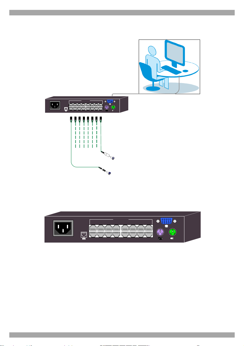
3. The Smart CAT5 system configuration
Figure 1 illustrates the basic configuration of the Smart CAT5 system.
Workstation
SMART CAT5SWITCH 116
www.minicom.com
POWER
100-240VAC 50/60 Hz
COMPUTER
10 11 12 13 14 15 169
1 2 3 4 5 6 7 8
To servers
M
O
C
I
N
I
M
RoC/RICCs
to servers
Figure 1 Smart CAT5 system configuration
4. The Smart CAT5 models
The figure below illustrates the rear panel of the Smart CAT5 116. The 108 model is
the same but with only 8 Computer ports.
www.minicom.com
POWER
100-240 VAC 50/60Hz
1 2 3 4 5 6 7 8
Figure 2 Smart CAT5 116 rear panel
COMPUTER
10 11 12 13 14 15 169
5. Pre-installation guidelines
Switch off all computers
Place cables away from fluorescent lights, air conditioners, and machines that are
likely to generate electrical noise
Ensure that the maximum distance between each computer and the Smart CAT5,
does not exceed 10m/33ft
1
Page 3

QUICK START GUIDE
6. Connecting the Smart CAT5 system
Each computer / server is directly connected to the Smart CAT5 via the appropriate
ROC using CAT5 cable in a star configuration. No external power is needed at the
remote ROCs. The ROCs draw their power from the computer’s keyboard port (ROC
PS/2) or from the USB port (ROC USB). The figures below illustrate the ROC PS/2
and ROC USB.
To computer’s
Video Card
To computer’s
Video card
To computer’s
keyboard port
To computer’s
mouse port
Figure 3 ROC PS/2
To computer’s
USB Port
Figure 4 ROC USB
Connecting the KVM console
Connect a KVMconsole to the Smart CAT5 as illustrated in Figure 1 above.
Connecting a ROC to each computer
Connect the ROCs as detailed in the figures above.
Connecting the CAT5 cables
1. Connect one connector to the ROC’s RJ45 port.
2. Connect the other connector to one of the Smart CAT5’s Computer ports.
3. Follow the above 2 steps for each computer.
7. Connecting the power supply
1. Connect the Smart CAT5 to the power supply using the Power cable provided. Use
only power cord supplied with the unit.
2. Switch on the computers.
8. Operating the Smart CAT5 system
Below is a brief outline of how to switch between computers. See the softcopy User
Guide for the full operating details.
2
Page 4

SMART CAT5 SWITCH – 108/116
Switch between the connected computers by either
The front panel Select buttons
Keyboard hotkeys - To switch to the next computer forwards press Shift then,
+. Release Shift, before pressing +. To switch to the next computer backwards
press Shift then, -. Release Shift, before pressing -.
Control software (See softcopy User Guide)
The OSD
The OSD is also the place to adjust various settings as explained in the softcopy User
Guide.
When switching computers the illuminated LED of the top row indicates which
computer is currently selected.
9. The OSD
To display the OSD:
Press Shift twice. The OSD Main window appears.
Navigating the OSD
To navigate up and down use the Up and Down arrow keys.
To exit the OSD press Esc.
10. Selecting a computer
To select a computer:
1. Navigate to the desired computer line.
Or, type the port number of the desired computer.
2. Press Enter. The selected computer is accessed. An OSD label appears showing
which computer is accessed.
Note! When the OSD is displayed you cannot select computers using the front panel
Select buttons or the keyboard hotkeys.
11. Resetting the switch
To reset the switch press the 2 front panel Select buttons simultaneously. The ROCs
are unaffected by this reset.
For the rest of the configuration and operating instructions please see the softcopy User
Guide on the supplied CD or on our website
http://www.minicom.com/supportuserguides.htm
3
201204197 •933194_EN
 Loading...