

Page 1
Quick Start Guide
NetCommander® IP
Cat5 KVM Switch
Model: B070-016-19-IP2
(Series Number: AG-00C3)
Note: Please visit www.tripplite.com/support for the full product manual.
Legal Notice 2
1. Product Overview 2
2. Web Configuration Interface 11
3. Conducting a Remote Session 12
4. Local Console 13
5. Warranty and Product Registration 14
PROTECT YOUR INVESTMENT!
Register your product for quicker service and ultimate peace of mind.
You could also win an ISOBAR6ULTRA surge protector—a $100 value!
www.tripplite.com/warranty
1111 W. 35th Street, Chicago, IL 60609 USA • www.tripplite.com/support
Copyright © 2017 Tripp Lite. All rights reserved. All trademarks are the property of their respective owners.
1
Page 2

Legal Notice
This guide and the software described in it are furnished under license, and may be used or copied only in accordance with the terms of
such license. The content of this guide is provided for informational use only, and is subject to change without notice. It should not in and of
itself be construed as a commitment by Tripp Lite, which assumes no responsibility of liability for any errors or inaccuracies that may appear
in this guide.
The software that accompanies this guide is licensed for use by the Licensee only, in strict accordance with the software license agreement,
which the Licensee should read carefully before commencing use of the software. Except as permitted by the license, no part of this
publication may be reproduced, stored in retrieval system, or transmitted in any form or by any means, electronic, mechanical, recording, or
otherwise, without the prior written permission of Tripp Lite.
1. Product Overview
1.1 Features and Benefits
• Directly connect up to 16 computers/servers.
• Up to 3 users (1 local, 2 remote) can simultaneously access the KVM.
• Up to 5 users can share a single remote session.
• Multi-level account access: Administrator and User account types.
• Remote authentication support; RADIUS and LDAP/S.
• Supports both IPv4 and IPv6.
• PDU Control - Add IP PDUs as devices that can be controlled by the KVM. Assign individual ports on the KVM to a PDU port to power cycle
or power off/on the computer/server connected to that port.
• BIOS level control to any server’s brand and model, regardless of the server condition and network connectivity. Covers the entire spectrum
of crash scenarios.
• Compatible with Windows® and Linux® operating systems.
• Connect computer/servers up to 100 ft. (30 m) away from the KVM using inexpensive Cat5e/6 cabling* and B078-101-USB2,
B078-101-USB-1 and B078-101-PS2 SIUs.
• Java-based application allows control of a target server via web browser from any location over a secured IP connection.
• Features two 10/100 Mbps LAN ports, so that if one fails, the other takes over.
• Supports the highest security standards for encryption (128-bit AES and HTTPS).
• Virtual Media allows an .iso file located in a Shared folder of a SAMBA or NFS server to be mounted to a Target Server and accessed as if
it were directly stored on it.
• Supports Virtual Media data transfer rates up to 12Mbps (B078-101-USB2 required). A B078-101-USB-1 can be used to provide Virtual
Media support, but only at speeds up to 1Mbps.
• Event log records events that take place on the installation, such as logins, reboots, network settings changes, etc..
• Features two RJ45 serial ports for connecting serial manageable devices, such as PDUs, firewalls, and routers.
• Allows for system sent messages to SNMP server to notify of LAN failures.
• Allows for the installation of a SSL certificate to ensure secure transactions between the Web servers and browsers.
• Graphical OSD and toolbars provide convenient, user-friendly remote operation.
• Text based OSD provides convenient, user-friendly local operation.
• Supports video resolutions up to 1920 x 1080 @ 60Hz. (B070-console KVMs are limited to video resolutions up to 1366 x 768 at the
local console.)
• Flash upgradeable firmware over the network.
* To ensure proper functionality, shielded Cat5e/6 cable must be used with the B078-101-USB2, and is recommended for all other SIUs for best performance.
2
Page 3

1. Product Overview
1.2 Terminology
The following table describes terms used in this guide.
Term Definition
Target Server
Client Computer
Remote Session
RICCs/ROCs/SIUs
1.3 Target Server Compatibility
• PS/2 and USB computers/servers.
• Computer/servers with an HD15 (VGA) port.
• Computer/servers running Windows or Linux operating systems.
1.4 Client Computer Compatibility
• Pentium 4 with 2 GB memory
• Supports Windows and Linux operating systems.
• Windows operating systems can use Internet Explorer®, Firefox®, or Chrome™ browsers.
• Linux operating systems can use Firefox or Chrome browsers.
The computer/server connected directly to the KVM, and which is accessed via the local console or by a Client
Computer running a remote session.
A computer running a remote session, which is used to access computer/servers or devices connected to the KVM.
The process of remotely accessing the KVM via Client Computer, and controlling Target Servers and other
connected devices.
RICC, ROC, and SIU refer to the dongles used to connect the KVM switch to a computer/server via Cat5e/6 cable.
RICCs are the earliest versions of these dongles, and stand for Remote Interface Connection Cable. ROCs are the
second generation of these dongles, and stand for RICC on Cable. SIUs are the current versions of these dongles,
and stand for Server Interface Units. Functionally, they all serve the same purpose. The B078-101-PS2, B078101-USB-1, and B078-101-USB2 are the SIUs that will be used with the NetCommander UP KVM Switches.
1.5 Safety
• Read all of these instructions. Save them for future reference.
• Follow all warnings and instructions marked on the device.
• Use of this equipment in life support applications where failure of this equipment can reasonably be expected to cause the failure of the
life support equipment or to significantly affect its safety or effectiveness is not recommended.
• This device is designed for IT power distribution systems with up to 230V phase-to-neutral voltage.
• Do not place the device on any unstable surface (cart, stand, table, etc.). If the device falls, serious damage will result.
• Do not use the device near water.
• Do not place the device near, or over, radiators or heat registers.
• The device cabinet is provided with slots and openings to permit adequate ventilation. To ensure reliable operation and protect against
overheating, these openings must never be blocked or covered.
• The device should not be placed on a soft surface (bed, sofa, rug, etc.), as this will block its ventilation openings. Likewise, the device
should not be placed in a built-in enclosure unless adequate ventilation has been provided.
• Never spill liquid of any kind on the device.
• Unplug the device from the wall outlet before cleaning. Use a damp cloth for cleaning. Do not use liquid or aerosol cleaners.
• The device should be operated from the type of power source indicated on the marking label. If you are not sure of the type of power
available, consult your dealer or local power company.
• To prevent damage to your installation, ensure that all devices are properly grounded.
• The device is equipped with a 3-wire grounding type plug. This is a safety feature. If you are unable to insert the plug into the outlet,
contact your electrician to replace your obsolete outlet. Do not attempt to defeat the purpose of the grounding-type plug. Always follow
your local/national wiring codes.
• Position system cables and power cables carefully to ensure that nothing rests on any cable. Route the power cord and cables so that
they cannot be stepped on or tripped over.
• If an extension cord is used with this device, make sure that the total ampere rating of all products used on the cord does not exceed the
extension cord ampere rating. Make sure that the total of all products plugged into the wall outlet does not exceed 15 amperes.
3
Page 4

1. Product Overview
• To help protect your system from sudden transient increases and decreases in electrical power, it is recommended that you plug your
devices into a Tripp Lite surge protector, line conditioner, or uninterruptible power supply (UPS).
• When connecting or disconnecting power to hot-pluggable power supplies, observe the following precautions:
o Install the power supply before connecting the power cable to the power supply.
o Unplug the power cable before removing the power supply.
o If the system has multiple sources of power, disconnect power from the system by unplugging all power cables from the power supplies.
o Never push objects of any kind into or through cabinet slots. They may touch dangerous voltage points or short out parts, resulting in a
risk of fire or electrical shock.
o Do not attempt to service the device yourself. Refer all servicing to qualified service personnel.
• If the following conditions occur, unplug the device from the wall outlet and bring it to qualified service personnel for repair:
o The power cord or plug has become damaged or frayed.
o Liquid has been spilled into the device.
o The device has been exposed to rain or water.
o The device has been dropped or the cabinet has been damaged.
o The device exhibits a distinct change in performance, indicating a need for service.
o The device does not operate normally when the operating instructions are followed.
• Adjust only those controls that are covered in the operating instructions. Improper adjustment of other controls may result in damage that
will require extensive repair work by a qualified technician.
1.6 System Components
Before installing the NetCommander IP KVM, verify that you have all the components on the following list, as well as any other items
required for installation.
• B070-016-19-IP2 NetCommander IP KVM.
• A B078-101-PS2, B078-101-USB-1 or B078-101-USB2 (ordered separately) for each computer/server you will be connecting.
• Cat5e/6 cable* (ordered separately) for each computer/server you will be connecting, as well as for network and serial connections.
• Rackmount hardware (included).
• Power cord (included).
* To ensure proper functionality, shielded Cat5e/6 cable must be used with the B078-101-USB2, and is recommended for all other SIUs for best performance.
4
Page 5
1. Product Overview
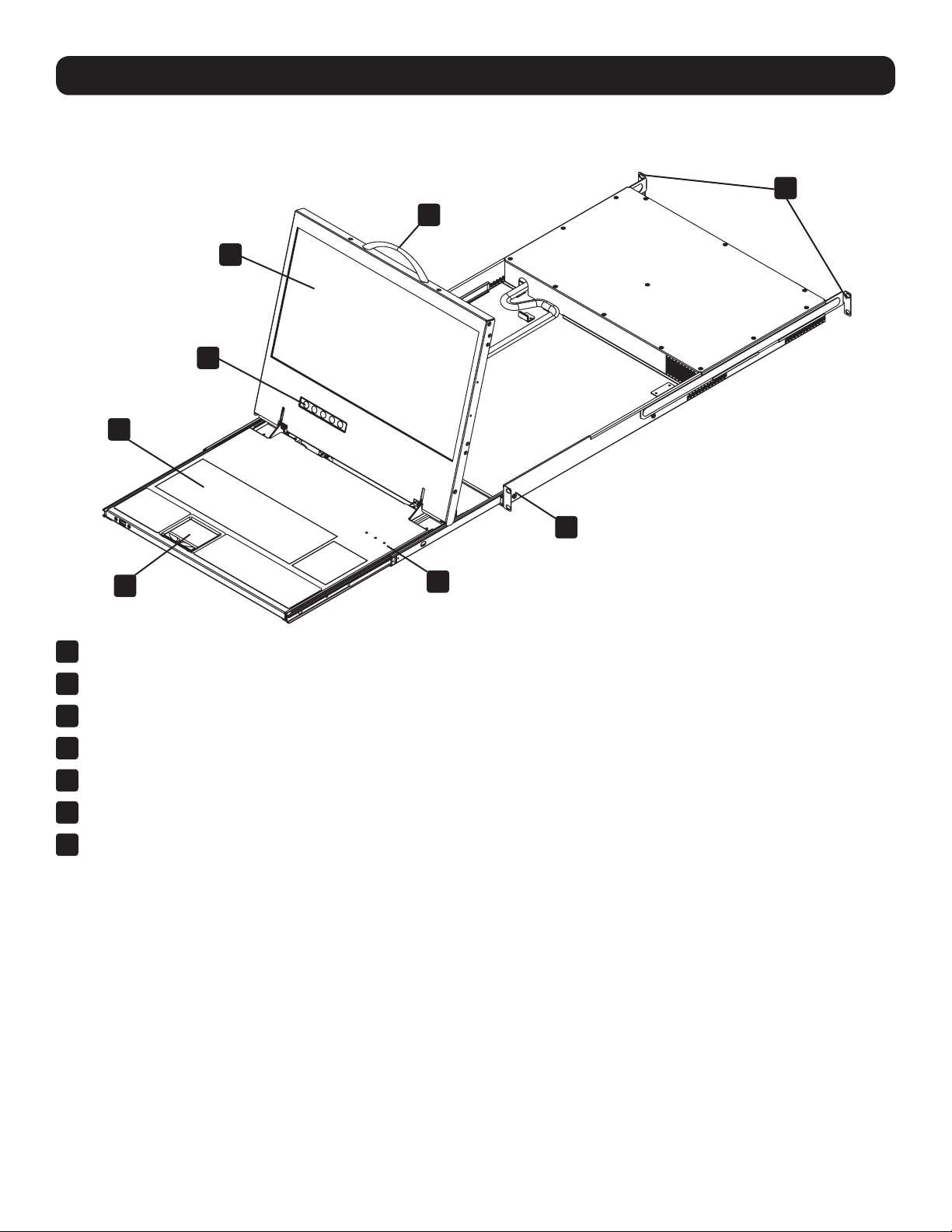
1.7 The NetCommander IP Unit
Console KVM Switch Front View
2
3
4
6
1
6
5
1
Upper Handle – Pull to slide the console out; push to slide the console in.
2
19” LCD Screen – After sliding the console out, flip up the cover to access the LCD screen, keyboard and touchpad.
3
LCD Controls – The LCD On/Off button is located here, as well as buttons to control the position and picture settings of the LCD screen.
4
Keyboard
5
2-Button Touchpad
6
Rackmounting Brackets – Secure the chassis to a system rack located at each corner of the unit.
7
Lock LEDs – The Num Lock, Caps Lock, and Scroll Lock LEDs are located here.
7
5
Page 6

1. Product Overview
Console KVM Switch Rear View
3 4 6
1 2
1
Power Outlet – The power cord included with the console connects to the unit here.
2
Reset Button – Pressing this button for 10 seconds restores the system to its factory default settings.
3
Serial Ports 1 and 2 – The KVM features two RJ45 serial ports for connecting serial manageable devices, such as PDUs, firewalls, and
routers (see the Serial Pinout section in the Owner’s Manual for the pinout information).
4
LAN Ports 1 and 2 – The KVM features two RJ45 LAN ports for connecting to 10/100 Mbps networks. If LAN 1 goes down, LAN 2
takes over. When LAN 1 becomes operational again, the KVM will need to be rebooted to make it the default LAN port again.
Note: Only one LAN port can be turned on at a time; they cannot both be turned on. If you don’t wish to use network redundancy, connect a single
network cable to the LAN 2 Port.
5
USB Port – This port currently serves no functional purpose. It is included for future functionality upgrades.
6
Server Ports – When connecting a computer/server, Cat5e/6* cabling connects from an available server port to a B078-101-PS2,
B078-101-USB-1 or B078-101-USB2 SIU which in turn connects to the computer/server.
* To ensure proper functionality, shielded Cat5e/6 cable must be used with the B078-101-USB2, and is recommended for all other SIUs for best performance.
5
1.8 Rackmounting the NetCommander IP
Follow all instructions in section 1.5 Safety of this guide before rackmounting. Make sure to write down the MAC Address and Device Number
located on the bottom of the unit before rackmounting, as they will be useful when finding the IP address assigned by the DHCP server. The
KVM comes with removable rackmount brackets, allowing the unit to be installed by a single person.
1.8.1 Standard Console KVM Switch Instructions
1
Remove the rackmount brackets from the unit and mount them to the back of the rack using user-supplied screws.
2
Take the Console KVM switch and gently slide it into the rack so that it inserts into the rackmount brackets you just mounted.
3
Mount the rackmount brackets on the front of the unit to the rack using user-supplied screws.
1 2-3
1.8.2 2-Post Rack Console KVM Switch Instructions
The B070-Series Console KVM Switches can be mounted to a 2-Post Rack using Tripp Lite’s B019-000 2-Post Rackmount Kit (sold
separately). See the B019-000 Owner’s Manual for installation instructions.
6
Page 7

1. Product Overview
1.9 Connecting the System
The figure below illustrates the NetCommander IP system overview.
1. Make sure that power to all the devices you will be connecting has been turned off.
2. Connect a Cat5e/6* cable from an available server port on the back of the KVM to an SIU (B078-101-PS2, B078-101-USB-1 or B078-
101-USB2) appropriate for the computer you are adding.
3. Connect the SIU’s connectors to the corresponding ports on the computer/server.
4. Repeat steps 2 and 3 for each computer/server you are adding.
5. Connect a Cat5e/6 cable from your network to the LAN 1 port on the back of the KVM.
6. Connect a second Cat5e/6 cable from your network into the KVM’s LAN 2 port.
7. Optional: Connect up to two serial devices to the RJ45 Serial Ports 1 and 2 on the back of the KVM switch (See the Configuring Serial
Port Settings section of the Owner’s Manual for details on configuration. See the Serial Pinout section in the Owner’s Manual for the
pinout information).
8. Connect the included power cord between the C14 outlet on the back of the unit and a Tripp Lite Surge Protector, Power Distribution Unit
(PDU), or Uninterruptible Power Supply (UPS). There is no Power On/Off switch, so plugging in the power cord will power
on the KVM.
9. Turn on the power to all of the connected devices.
* To ensure proper functionality, shielded Cat5e/6 cable must be used with the B078-101-USB2, and is recommended for all other SIUs for best performance.
1.10 Initial Settings (Default IP Address)
By default, the NetCommander IP is set to have the network’s DHCP server pull an IPv4 address. Referencing the unit’s MAC address (found
on the bottom panel of the KVM), have your network administrator provide you with the IP address assigned by the DHCP server. You can
also obtain the IP address by logging into the KVM’s OSD via the local console and navigating to the F2 Settings menu.
On networks that do not have a DHCP server, the KVM boots with the default static IPv4 address of 192.168.0.254.
Note: There is no default IPv6 address for the KVM switch. An IPv6 address can be automatically assigned via DHCP server, a Stateless address can be
assigned, or a static address can be manually entered.
To configure an IP address for the KVM, you can use the local console OSD or the Web Configuration Interface. Both methods are described
in the following sections.
7
Page 8

1. Product Overview
To set the IPv4 address via the local console OSD:
1. From the local console, press the left [Shift] key twice to open
the OSD.
2. Press the [F2] key to open the Settings menu.
3. In the Settings menu, press the [Tab] key until the DHCP field is
highlighted. Press the [Spacebar] key to toggle the DHCP field
from Enabled to Disabled.
4. Pressing the [Tab] key to navigate to the additional fields, type
in the desired IP Address, Subnet Mask, Gateway and DNS
Server Address (optional).
5. Once the IP address is satisfactory, press the [Esc] key to save
your changes. This will require that the KVM be rebooted to
save the new settings.
To set the IPv6 address via the local console OSD:
1. From the local console, press the left [Shift] key twice to open the OSD.
2. Press the [F2] key to open the Settings menu, and then press the
[F2] key again to open the IPv6 Settings menu.
3. In the IPv6 Settings menu, with the Mode field at the top of the screen
highlighted, press the [Spacebar] key to toggle between DHCP,
Stateless, and Static. DHCP is selected by default, and automatically
assigns an IP address via the IPv6 DHCP server. Stateless is an
option for networks with a compliant router that performs Stateless IPv6
configuration. Static allows you to manually assign an IP address.
4. Pressing the [Tab] key to navigate to the additional fields, type in the
desired IP Address, Gateway, and DNS Server Address (optional).
Note: DNS IP should be set to 0.0.0.0 to indicate no DNS.
5. Once the IP address is satisfactory, press the [Esc] key twice to exit
and save your changes. This will require that the KVM be rebooted to
save the new settings.
To set the IP address via the Web Configuration Interface:
Note:
• Before logging on the first time, verify that you have the latest Java installed on your computer (Java 1.6 or higher is required). If not, you
can download and install Java from http://www.java.com/en/download/index.jsp.
• Only SSL connections are allowed, so you must start the IP address with HTTPS, not HTTP.
1. Open your web browser (see section 1.4 Client Computer Compatibility in this guide for browser support) and enter the IP address of the
KVM.
2. When logging into the KVM from your web browser, a Security Alert message appears to inform you that the device’s certificate is not
trusted, and asks if you want to proceed. You have two options:
• If you are working on a computer other than your own, accept the certificate for just this session by clicking to proceed.
• If you are working at your own computer, install the certificate. Reference the instructions in section 6. Security Certificate Installation
in the Owner’s Manual.
8
Page 9

1. Product Overview
3. Upon installing the certificate or accepting the unrecognized certificate for the current session, the initial web page appears and the
Java application is launched. Before the installation completes, a security warning may appear stating that the connection to this
website is untrustworthy. This is a security issue similar to one you get from your web browser. You can choose to continue anyway,
or install the certificate in the Java control panel. Refer to section 6. Security Certificate Installation in the Owner’s Manual for further
instructions.
4. After the Java application is launched, the login page appears. If the login page does not appear on its own, click the Log On button in
the center of the web page to bring it up. If clicking on the Log On button does not bring up the login page, add /targets.jnlp to the end
of your IP address.
5. Enter in your username and password, and press Enter. If this is the first time you are accessing the KVM, enter in the default
username (admin) and password (access). The My Targets page of the Web Configuration Interface opens, showing the state of your
unit and displaying all your available Target Servers.
6. Click on the Configuration icon at the top of the screen to pull up the KVM’s Configuration screen. It opens with the Device tab
displayed.
9
Page 10

1. Product Overview
7. There are two LAN sections in the Device tab, one for IPv4 and one for IPv6. For IPv4, you have the options of automatically assigning
an address via DHCP server (default) and manually assigning an address. For IPv6, you have the options of automatically assigning an
address via DHCP server (default), automatically assigning a stateless address, manually assigning an address, or disabling IPv6
altogether. Make the desired selections, depending on how you wish the IP address to be assigned.
8. Populate the fields in the IPv4 or IPv6 sections with the desired network information.
9. Click the Save icon in the toolbar above the Configuration menu tabs to save the network settings. Upon clicking Save, you will be
prompted to reboot the KVM to finish the implementation of the new Device settings. Click Yes to proceed.
10
Page 11

2. Web Configuration Interface
The NetCommander IP can be accessed in two ways: locally via the local console OSD, or remotely via the Web Configuration Interface. This
section details the Web Configuration Interface, which can be used to access the computer/servers and other devices connected to the KVM,
as well as to configure the KVM’s settings and accounts.
2.1 Logging Into the Web Configuration Interface
Note:
• Before logging on the first time, verify that you have the latest Java installed on your computer (Java 1.6 or higher is required). If not, you
can download and install Java from http://www.java.com/en/download/index.jsp.
• Only SSL connections are allowed, so you must start the IP address with HTTPS, not HTTP.
1. Open your web browser (see section 1.4 Client Computer Compatibility in this guide for browser support) and enter the IP address of the KVM.
2. When logging into the KVM from your web browser, a Security Alert message appears to inform you that the device’s certificate is not
trusted, and asks if you want to proceed. You have two options:
• If you are working on a computer other than your own, accept the certificate for just this session by clicking to proceed.
• If you are working at your own computer, install the certificate. Reference the instructions in section 6. Security Certificate Installation
in the Owner’s Manual.
3. Upon installing the certificate or accepting the unrecognized certificate for the current session, the Java application begins to install.
Before the installation completes, a security warning may appear stating that the connection to this website is untrustworthy. This is
a security issue similar to one you get from your web browser. You can choose to continue anyway, or install the certificate in the Java
control panel. Refer to section 6. Security Certificate Installation in the Owner’s Manual for further instructions.
4. After installation has completed, the login page appears. If the login page does not appear on its own, click the Log On button in the
center of the web page to bring it up. If clicking on the Log On button does not bring up the login page, add /targets.jnlp to the end of
your IP address.
5. Enter in your username and password, and press Enter. If this is the first time you are accessing the KVM, enter in the default
username (admin) and password (access). The My Targets page of the Web Configuration Interface opens, showing the state of your
unit, and displaying all your available Target Servers.
11
Page 12

3. Conducting a Remote Session
A remote session allows accounts IP access to computer/servers and serial devices connected to the KVM. In a remote session, accounts
can access computers/servers, power cycle or turn power to a Target Server Off/On, virtually mount an .iso file, and configure the remote
session settings. The sections that follow explain the features of a remote session, and how to use them.
3.1 Starting a Remote Session
To start a remote session:
1. Open the Web Configuration Interface, and click on the
only those ports that the logged-in account is permitted to use. For administrator accounts, a graphic of the KVM’s back panel is
displayed in between the Toolbar and Data Pane.
icon in the menu bar. The My Targets screen appears, displaying
2. A remote session can be initiated in one of four ways:
• Select a port from the Data Pane of the My Targets screen, and click on the Display icon in the toolbar.
• Select a port from the Data Pane of the My Targets screen, and press the [Enter] key.
• Double-click on a port in the Data Pane of the My Targets screen.
• Administrator’s Only – Double-click on a port in the graphic of the KVM’s rear panel.
Note: A Target Server with a Remote Exclusive Session or Local Exclusive Session status is being accessed by another account in
Exclusive Mode (see section 3.4 Exclusive Session in the Owner’s Manual for details), and cannot be accessed. A Target Server with a
Remote Session status is being accessed by another account in Share Mode, which allows for up to 5 users to access the port at the
same time (see section 3.3 Shared Session in the Owner’s Manual for details).
3. Upon initiating a remote session in one of these four ways, the screen of the selected Target Server appears inside a remote console
window with the remote session toolbar displayed.
12
Page 13

4. Local Console
This section explains how to operate the NetCommander IP via the local console. The local console allows you to access connected
computer/servers, configure the KVM’s network settings, and to configure some more basic settings specific to local access.
To display the OSD:
1. From the local keyboard, press the left Shift key twice. The
OSD Main window appears.
Lines with sun icons in the PM column show active computers/
servers. A computer that is connected, but is powered-off, does
not have a sun icon. When a server is busy (when an account is
accessing it in an Exclusive Session), the entire line appears in red
characters.
Navigating the OSD:
• To move the highlight bar throughout the list, press the [h] and [i] arrow keys.
• To jump from one column to the next (when relevant), press the [Tab] key.
• To exit the OSD or return to a previous window within the OSD, press the [Esc] key.
To select a computer:
1. Navigate to the desired port using the [h] and [i] arrow keys, or type the two-digit port number of the desired computer.
2. Press the [Enter] key. The selected computer is accessed.
13
Page 14

5. Warranty and Product Registration
1-Year Limited Warranty
TRIPP LITE warrants its products to be free from defects in materials and workmanship for a period of one (1) year from the date of initial purchase. TRIPP LITE’s obligation under this
warranty is limited to repairing or replacing (at its sole option) any such defective products. To obtain service under this warranty, you must obtain a Returned Material Authorization
(RMA) number from TRIPP LITE or an authorized TRIPP LITE service center. Products must be returned to TRIPP LITE or an authorized TRIPP LITE service center with transportation
charges prepaid and must be accompanied by a brief description of the problem encountered and proof of date and place of purchase. This warranty does not apply to equipment
which has been damaged by accident, negligence or misapplication or has been altered or modified in any way.
EXCEPT AS PROVIDED HEREIN, TRIPP LITE MAKES NO WARRANTIES, EXPRESS OR IMPLIED, INCLUDING WARRANTIES OF MERCHANTABILITY AND FITNESS FOR A PARTICULAR
PURPOSE. Some states do not permit limitation or exclusion of implied warranties; therefore, the aforesaid limitation(s) or exclusion(s) may not apply to the purchaser.
EXCEPT AS PROVIDED ABOVE, IN NO EVENT WILL TRIPP LITE BE LIABLE FOR DIRECT, INDIRECT, SPECIAL, INCIDENTAL OR CONSEQUENTIAL DAMAGES ARISING OUT OF THE USE OF
THIS PRODUCT, EVEN IF ADVISED OF THE POSSIBILITY OF SUCH DAMAGE. Specifically, TRIPP LITE is not liable for any costs, such as lost profits or revenue, loss of equipment, loss
of use of equipment, loss of software, loss of data, costs of substitutes, claims by third parties, or otherwise.
PRODUCT REGISTRATION
Visit www.tripplite.com/warranty today to register your new Tripp Lite product. You’ll be automatically entered into a drawing for a chance to win a FREE Tripp Lite product!*
* No purchase necessary. Void where prohibited. Some restrictions apply. Open to U.S. residents only. See www.tripplite.com for details.
FCC Notice, Class A
This device complies with part 15 of the FCC Rules. Operation is subject to the following two conditions: (1) This device may not cause harmful interference, and (2) this device must
accept any interference received, including interference that may cause undesired operation.
Note: This equipment has been tested and found to comply with the limits for a Class A digital device, pursuant to part 15 of the FCC Rules. These limits are designed to provide
reasonable protection against harmful interference when the equipment is operated in a commercial environment. This equipment generates, uses, and can radiate radio frequency
energy and, if not installed and used in accordance with the instruction manual, may cause harmful interference to radio communications. Operation of this equipment in a
residential area is likely to cause harmful interference in which case the user will be required to correct the interference at his own expense. The user must use shielded cables and
connectors with this equipment. Any changes or modifications to this equipment not expressly approved by Tripp Lite could void the user’s authority to operate this equipment.
WEEE Compliance Information for Tripp Lite Customers and Recyclers (European Union)
Tripp Lite follows a policy of continuous improvement. Specifications are subject to change without notice.
Under the Waste Electrical and Electronic Equipment (WEEE) Directive and implementing regulations, when customers buy new electrical and electronic equipment
from Tripp Lite they are entitled to:
• Send old equipment for recycling on a one-for-one, like-for-like basis (this varies depending on the country)
• Send the new equipment back for recycling when this ultimately becomes waste
1111 W. 35th Street, Chicago, IL 60609 USA • www.tripplite.com/support
14
17-01-245 93-3678_revB
 Loading...