


Owner’s Manual
NetDirector Console KVM Switch
(8- or 16-Port) or
Rackmount KVM Switch (8-Port)
Models: B020-U08-19-K, B020-U08-19KTAA, B020-U16-19-K or
B022-U08
PROTECT YOUR INVESTMENT!
Register your product for quicker service and ultimate peace of mind.
You could also win an ISOBAR6ULTRA surge protector—a $100 value!
www.tripplite.com/warranty
1111 W. 35th Street, Chicago, IL 60609 USA • www.tripplite.com/support
Copyright © 2016 Tripp Lite. All rights reserved.
1

Table of Contents
1. Package Contents 2
2. Features 2
3. System Requirements 3
3.1 Computer 3
3.2 Console 3
3.3 Cables 3
4. Introduction 4
4.1 Front View of Console KVM Switch 4
4.2 Front View of B022-U08 5
4.3 Rear View of Console KVM Switch 5
4.4 Rear View for B022-U08 6
5. Installation 6
5.1 Pre-Installation Safety Instructions 6
5.2 Rackmounting Instructions for Console KVMs 7
5.3 Rackmounting for B022-U08 8
5.4 Grounding 8
5.5 Single-Station Installation 8
5.6 Multiple-Station (Daisy-Chained) Installation 8
5.7 Multiple Station (Cascaded) Installation 8
5.8 Hot Plugging 9
6. Basic Operation 9
6.1 Opening the NetDirector Console KVM 9
6.2 Closing the NetDirector Console KVM 9
6.3 LCD OSD (On-Screen Display) Configuration 10
6.4 Sharing USB Peripheral Devices 10
6.5 Powering Off and Restarting 10
7. Hotkeys 11
7.1 Invoking the Hotkey Mode 11
7.2 Port ID Numbering 11
7.3 Selecting the Active Port 11
7.4 Auto Scanning 12
7.5 Starting Auto Scan 12
7.6 Pausing in Auto Scan 12
7.7 Skip Mode 12
7.8 Hotkey Beeper Control 12
7.9 Computer Keyboard/Mouse Reset 12
7.10 Quick Hotkey Control 13
7.11 OSD Hotkey Comtrol 13
7.12 Port OS Control 13
7.13 Restore Default Values 13
7.14 Hotkey Summary Table 13
8. OSD (On-Screen Display) Operation 14
8.1 OSD Overview 14
8.2 Logging-In for the First Time 14
8.3 OSD Invocation Sequence 14
8.4 OSD Navigation 14
8.5 OSD Main Screen Headings 14
8.6 OSD Functions 15
9. Firmware Upgrade Utility 18
9.1 Before You Begin 18
9.2 Starting the Upgrade 19
9.3 Upgrade Succeeded 19
9.4 Upgrade Failed 19
9.5 Firmware Upgrade Recovery 20
10. Appendix A 20
10.1 Specifications 20
10.2 OSD Factory Default Settings 21
10.3 Keyboard Emulation 21
11. Appendix B 22
11.1 FCC Radio/TV Interference Notice 22
12. Warranty and Product Registration 22
1. Package Contents
• (1) B020-U08-19-K, B020-U08-19KTAA, B020-U16-19-K or B022-U08 KVM Switch
• (8) P778-006 USB/PS2 Combo KVM Cable Kits*
• (1) USB/PS2 Combo Console Cable Kit
• (1) RJ45 to DB9 Firmware Upgrade Cable
• (1) C13 to 5-15P Power Cord*
• (1) AC Power Adapter (Input: 100-240V, 50/60 Hz, 0.5A/Output: 5.3V, 2.4A)**
• (1) CD with Owner’s Manual
• (1) Quick Start Guide
• (1) Grounding Wire
• (1) Rackmount Hardware Kit
• (1) Set of Rubber Feet**
*B020-U08-19-K, B020-U08-19KTAA and B020-U16-19-K only
**B022-U08 only
Check to see that the unit arrived undamaged and with all of its contents. Contact your dealer if there is a problem.
2. Features
• Integrated KVM console with 19” LCD for the B020-U08-19-K, B020-U08-19KTAA and B020-U16-19-K.
• B020-U08-19-K, B020-U08-19KTAA and B020-U16-19-K come with (8) P778-Series USB/PS2 Combo KVM Cable Kits.
2
2. Features
• B020-U08-19-K, B020-U08-19KTAA and B020-U16-19-K come with an external console port, allowing an external local console (PS/2 or USB) to
be connected. An additional USB port is included on the front panel of the B020-U08-19-K, B020-U08-19KTAA and B020-U16-19-K for use with
an external mouse.
• Dual Interface supports computers with PS/2 or USB keyboards and mice.
• Keyboard and mouse emulation (PS/2 and USB) allows for simultaneous booting of computers even when the console focus is elsewhere.
• External USB port allows for sharing of USB1.1 peripherals among all ports on the KVM switch.*
• Multiplatform support: supports Windows, Linux, Mac and Sun.
• Supports multimedia USB keyboards for PC, Mac and Sun.
• Daisy-chain up to 31 additional switches to connect up to 264 computers.
• The B022-U08 can be daisy-chained from the B020-U08-19-K, B020-U08-19KTAA, B020-U16-19-K, B020-U08-19-IP and B020-U16-19-IP.
• Daisy-chained station position is automatically sensed – no need for manual DIP switch settings.
• B022-U08 KVM Switches can be cascaded off of B020-016-17-IP Switches.**
• Station ID LED indicates the switch’s station position.
• No software required.
• Select a computer via push-buttons, Hotkeys or On Screen Display (OSD) menus.
• Auto-scan feature allows for continuous scanning of connected computers.
• Hot Pluggable: add/remove computers without powering down the KVM switch.
• Two-level password security: only authorized Users can view and control the connected computers. (Up to four Users and one Administrator).
• Superior video quality: supports resolutions up to 2048 x 1536 for the B022-U08 and 1280 x 1024 for the B020-U08-19-K, B020-U08-19KTAA
and B020-U16-19-K.
• Rackmountable in 19” rack system (1U).
• Firmware upgradeable.
*USB1.1 peripheral sharing function works only when using the USB Cable Kit connections.
**A separate firmware upgrade is required for cascading. (See Firmware Upgrade on Page 18 for details.
3. System Requirements
3.1 Computer
• A VGA, SVGA or MultiSync computer with a HD15 port
Note: The max resolution for the B020-U08-19-K, B020-U08-19KTAA or B020-U16-19-K is 1280 x 1024, and 2048 x 1536 for the B022-U08. The resolutions of the connected
computers must not exceed these limits.
Either:
1. A Mini-DIN 6 (PS/2) keyboard and mouse port.
2. A USB Type-A port.
3.2 Console*
• A VGA, SVGA, or MultiSync monitor capable of the highest resolution on any system in the installation
• A PS/2 or USB-style mouse
• A PS/2 or USB-style keyboard
*Optional external console ports are included on the NetDirector Console KVM Switches.
3.3 Cables
This KVM switch requires the following custom-wired premium cables:
Function Tripp Lite Part
To Connect a PS/2 or USB Computer to the KVM P778-Series PS/2 or USB Combo KVM Cable Kit
Daisy-Chain Cables P772- Series Daisy-Chain Cables
3.4 Operating Systems
OS Version
Windows 2000 and higher
Linux RedHat 7.1 and higher
Linux SuSE 9.0 and higher
Linux Mandriva (Mandrake) 9.0 and higher
UNIX AIX 4.3 and higher
OS Version
UNIX FreeBSD 4.2 and higher
UNIX Sun Solaris 8 and higher
Novell Netware 5.0 and higher
Mac OS 9 and higher
DOS 6.22
3
4. Introduction
4.1 Front View of Console KVM Switch
2
3
5
4
6
7
14
8
13
1
15
12
11
10
9
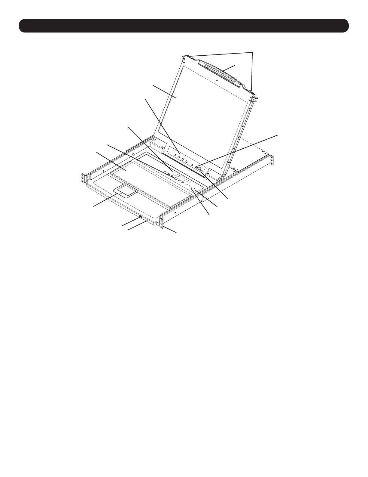
1. Handle
Pull to slide the KVM module out; push to slide the module in (see
item 13 in this table).
2. LCD
After sliding the KVM module out, flip up the cover to access the
LCD monitor.
3. LCD Controls
The LCD On/Off switch is located here, as well as buttons to control
the position and picture settings of the LCD display. See page 10 for
details.
4. Station/Port Switches
Press the Port ID up/down buttons to switch to the port before/after
the currently selected port. Press the Station ID up/down buttons
to switch to the station before/after the currently selected station.
5. LEDs
• Online Port LEDs – There are 8 or 16 LEDs (depending on the
number of ports) at the top of the keyboard panel that illuminate
orange when a computer is connected and powered-on
• Port ID LED – A numerical LED displays the number of the port
which currently has the focus of the KVM switch
• Station ID LED – A numerical LED displays the station number of
the KVM switch that currently has the focus of the console
6. Keyboard
7. Touchpad
8. Power LED
Lights BLUE to indicate that the unit is receiving power.
9. Rackmounting Tabs
The rackmounting tabs located at each corner of the unit secure the
chassis to a system rack. Refer to page 7 for rackmounting details.
10. Lock LEDs
The Num Lock, Caps Lock, Scroll Lock LEDs are located here.
11. Reset Switch
Located to the right of the Lock LEDs. Press this recessed switch
with a thin object to perform a system reset.
12. Firmware Upgrade Section
• Firmware Upgrade Port: The Firmware Upgrade Cable that
transfers the firmware upgrade data from the Administrator’s
computer to the Console KVM Switch plugs in here.
• Firmware Upgrade Switch: During normal operation, this switch
should be in the NORMAL position. (See page 18 for firmware
upgrading details.)
13. Slide Release
In order to bring the console out, you must first release it by sliding
these tabs to the inside. See page 9 for details on sliding the
console in and out.
14. External Mouse Port
An additional USB port is provided on the front panel of the
keyboard module for an optional external mouse.
15. USB Peripheral Port
A USB 1.1 port is provided for the sharing of USB peripherals
among connected computers (e.g. flash drive, CD-ROM drive, etc).
4
4. Introduction
4.2 Front View of B022-U08
1 2
65 7
34
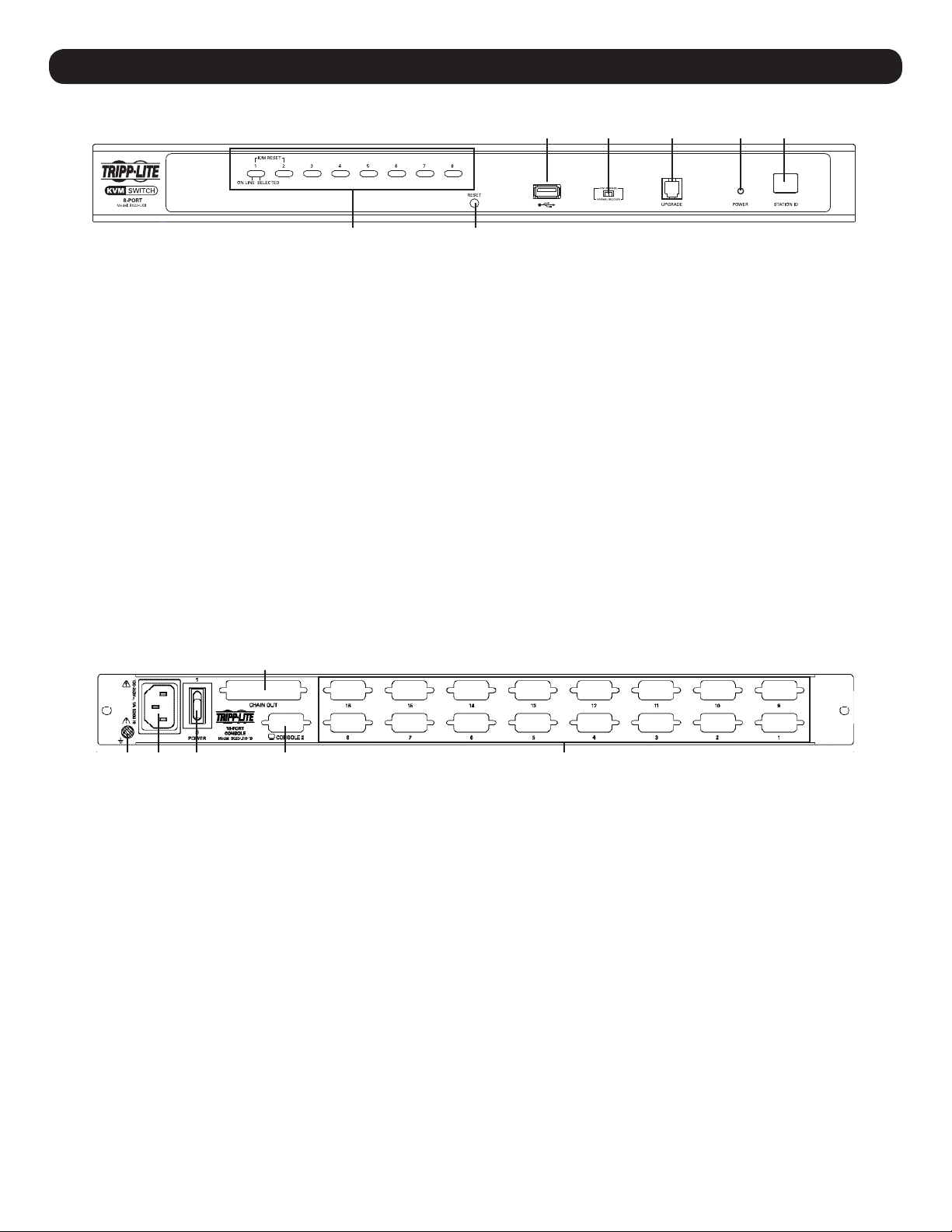
1. Port Push-buttons/LEDs
There are 8-port selection push-buttons on the front panel, all of
which contain two LEDs.
• Press the push-button of any port to switch the KVM’s focus to that
port
• An orange LED illuminates when a computer is connected to the
port and powered-on
• A green LED illuminates when the computer connected to the port
has the KVM’s focus
• Pressing push-buttons 1 and 2 simultaneously will perform a
keyboard and mouse reset
• Pressing push-buttons 7 and 8 simultaneously will start an Auto
Scan (see page 12 for Auto Scan details)
2. Reset Switch
Pressing this switch performs a system reset. This switch is semirecessed and must be pushed with a thin object, such as the end of
a paper clip or a ballpoint pen. Lights turn on to indicate that the
KVM is powered up and ready to operate.
4.3 Rear View of Console KVM Switch
1
3. Station ID LED
The B022-U08’s Station ID is displayed here. If this is a SingleStation Installation (see page 8) or the first station on a daisychained installation (see page 8), the unit has a Station ID of 01. On
a daisy-chained installation, the KVM auto-senses its position and
displays the Station ID that corresponds to its place in the chain (see
Port ID Numbering, page 11 for details).
4. USB Peripheral Port
A USB 1.1 port is provided for the sharing of USB peripherals among
connected computers (e.g. flash drive, CD-ROM drive, etc).
5. Firmware Upgrade Recovery Switch
During normal operation and while performing a firmware upgrade,
this switch should be in the NORMAL position. In the event of a
firmware upgrade failure, this switch is set to RECOVER to perform a
firmware upgrade recovery (see page 20 for firmware upgrade
recovery details).
6. Firmware Upgrade Port
The cable used to perform a firmware upgrade connects to the KVM
switch here.
7. Power LED
This LED illuminates when the KVM switch is powered On.
5 236 4
1. Daisy-Chain Port
When daisy chaining units, the cable plugs in here.
2. CPU Port Section
The cables that link to the computers plug in here.
3. Power Socket
This is a standard 3-prong AC power socket. The power cord from an
AC source plugs in here.
4. Power Switch
This is a standard rocker switch that powers the unit On and Off.
5. External Console Port
This port allows for the optional connection of an external keyboard,
mouse and monitor. The included USB/PS2 Combo Console Cable Kit
connects to the KVM switch here. Either USB or PS/2 keyboards/mice
can be connected.
6. Grounding Terminal
The included grounding wire connects to the KVM switch here.
5
4. Introduction
4.4 Rear View for B022-U08
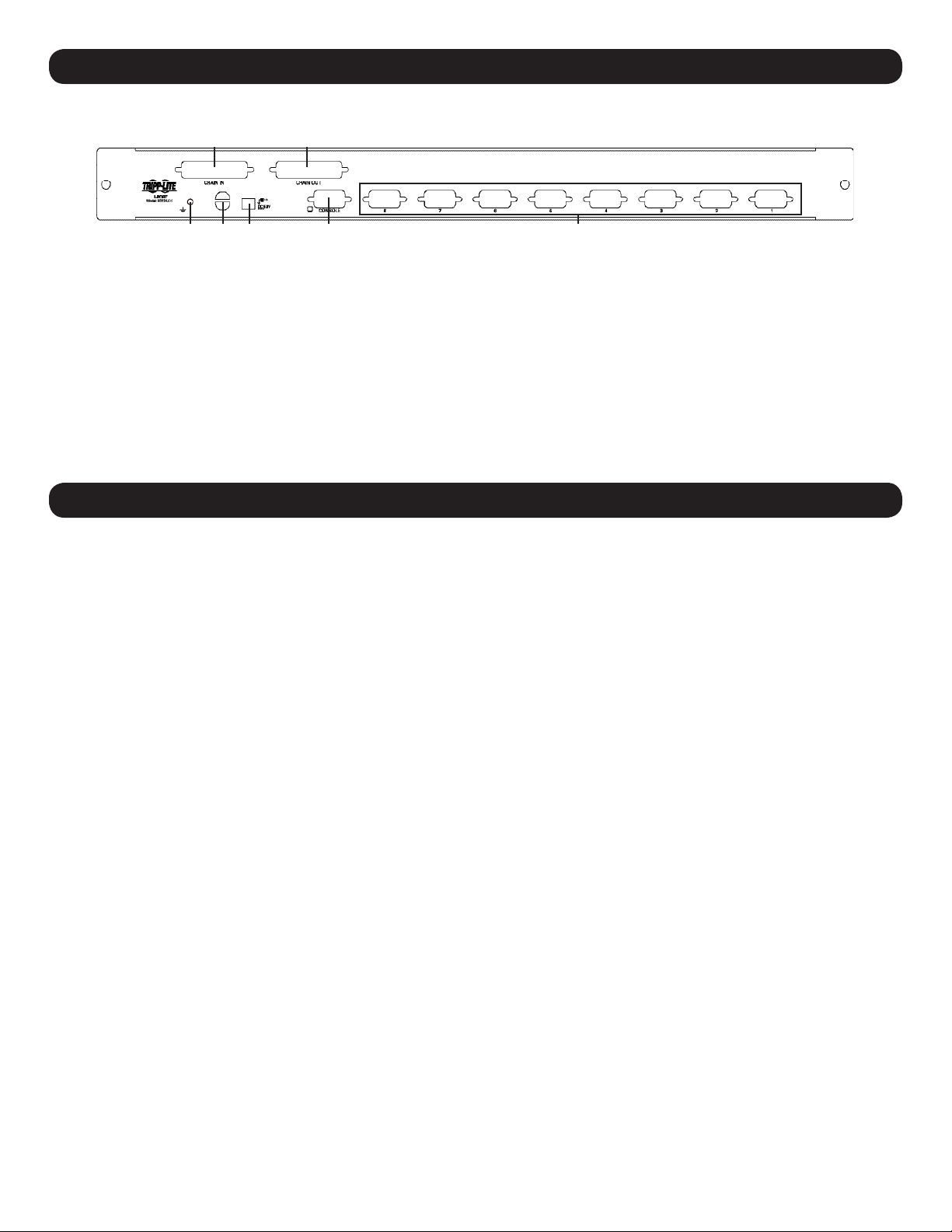
11
5 236 4
1. Daisy-Chain Port
• Daisy-Chain In Port – When daisy-chaining additional KVM
switches, the daisy-chain cable from the previous KVM switch in
the chain connects here. This port is not used if the KVM switch
occupies the first spot in a daisy-chain, or in a single-stage
installation
• Daisy-Chain Out Port – When daisy-chaining additional KVM
switches, the daisy-chain cable connects this port to the DaisyChain In Port on the next KVM switch in the chain
2. CPU Port Section
Plug the KVM cable for each computer into these ports.
5. Installation
3. Cable Management Slot
A cable tie can be used to gather the cables together and then be
tied to this slot to help manage the cables.
4. Power Port
The power adapter cable plugs into this port.
5. Console Port
The included USB/PS2 Combo Console Cable Kit connects to the
KVM switch here. A VGA monitor and either USB or PS/2 keyboards/
mice can be connected to the cable kit.
6. Grounding Terminal
The included grounding wire connects to the KVM switch here.
5.1 Pre-Installation Safety Instructions
Read all of these instructions and save them for future reference.
General Safety Instructions
• Follow all warnings and instructions marked on the device.
• Do not place the device on any unstable surface (cart, stand, table, etc.). If the device falls, serious damage will result.
• Do not use the device near water.
• Do not place the device near, or over, radiators or heat registers.
• The device cabinet is provided with slots and openings to allow for adequate ventilation. To ensure reliable operation, and to protect against
overheating, these openings must never be blocked or covered.
• The device should never be placed on a soft surface (bed, sofa, rug, etc.) as this will block its ventilation openings. Likewise, the device should not
be placed in a built in enclosure unless adequate ventilation has been provided.
• Never spill liquid of any kind on the device.
• Unplug the device from the wall outlet before cleaning. Do not use liquid or aerosol cleaners. Use a damp cloth for cleaning.
• The device should be operated from the type of power source indicated on the marking label. If you are not sure of the type of power available,
consult your dealer or local power company.
• The device is designed for IT power distribution systems with up to 230V phase-to-phase voltage.
• To prevent damage to your installation it is important that all devices are properly grounded.
• The device is equipped with a 3-wire grounding type plug. This is a safety feature. If you are unable to insert the plug into the outlet, contact an
electrician. Do not attempt to defeat the purpose of the grounding-type plug. Always follow your local/national wiring codes.
• Do not allow anything to rest on the power cord or cables. Route the power cord and cables so that they cannot be stepped on or tripped over.
• If an extension cord is used with this device make sure that the total of the ampere ratings of all products used on this cord does not exceed the
extension cord ampere rating. Make sure that the total of all products plugged into the wall outlet does not exceed 15 amperes.
• To protect against circuit overloading, you should plug your KVM switch and connected computers into a Tripp Lite SmartPro® or SmartOnline®
UPS System.
• Position system cables and power cables carefully, making sure that nothing rests on any cables.
• Never push objects of any kind into or through cabinet slots. They may touch dangerous voltage points or short out parts resulting in a risk of fire or
electrical shock.
• Do not attempt to service the device yourself. Refer all servicing to qualified service personnel.
6
5. Installation
• If the following conditions occur, unplug the device from the wall outlet and bring it to qualified service personnel for repair:
o The power cord or plug has become damaged or frayed
o Liquid has been spilled into the device
o The device has been exposed to rain or water
o The device has been dropped, or the cabinet has been damaged
o The device exhibits a distinct change in performance, indicating a need for service
o The device does not operate normally when the operating instructions are followed
• Only adjust those controls that are covered in the operating instructions. Improper adjustment of other controls may result in damage that will require
extensive work by a qualified technician to repair.
• Do not connect the RJ-11 connector marked “UPGRADE” to a public telecommunication network.
• Use of this equipment in life support applications where failure of this equipment can reasonably be expected to cause the failure of the life support
equipment or to significantly affect its safety or effectiveness is not recommended. Do not use this equipment in the presence of a flammable
anesthetic mixture with air, oxygen or nitrous oxide.
Rack Mounting Safety Instructions
• Before working on the rack, make sure that the stabilizers are secured to the rack, extended to the floor and that the full weight of the rack rests on
the floor. Install front and side stabilizers on a single rack or front stabilizers for joined multiple racks before working on the rack.
• Always load the rack from the bottom up and load the heaviest item in the rack first.
• Make sure that the rack is level and stable before extending a device from the rack.
• Use caution when pressing the device rail release latches and sliding a device into or out of a rack; the slide rails can pinch your fingers.
• After a device is inserted into the rack, carefully extend the rail into a locking position, then slide the device into the rack.
• Do not overload the AC supply branch circuit that provides power to the rack.
• The total rack load should not exceed 80 percent of the branch circuit rating.
• Make sure that all equipment used on the rack (including power strips and other electrical connectors) is properly grounded.
• Ensure that proper airflow is provided to devices in the rack.
• Ensure that the operating ambient temperature of the rack environment does not exceed the maximum ambient temperature specified for the
equipment by the manufacturer.
• Do not step on or stand on any device when servicing other devices in a rack.
5.2 Rackmounting Instructions for Console KVMs
The NetDirector Console KVM Switch is designed for mounting in a 1U rack system. For convenience, a rack mounting kit is included with your KVM
for quick installation. The mounting options are explained in the sections that follow:
Note:
1. It is recommended that the unit be installed by two people; one to hold it in place and the other to attach it to the rack.
2. The rackmounting kit that comes with the unit does not include screws or cage nuts. Contact your rack dealer for this hardware.
3. Allow at least 2 inches (5.1 cm) on each side for proper ventilation, and at least 5 inches (12.7 cm) at the rear of the unit for the power cord and cable kits.
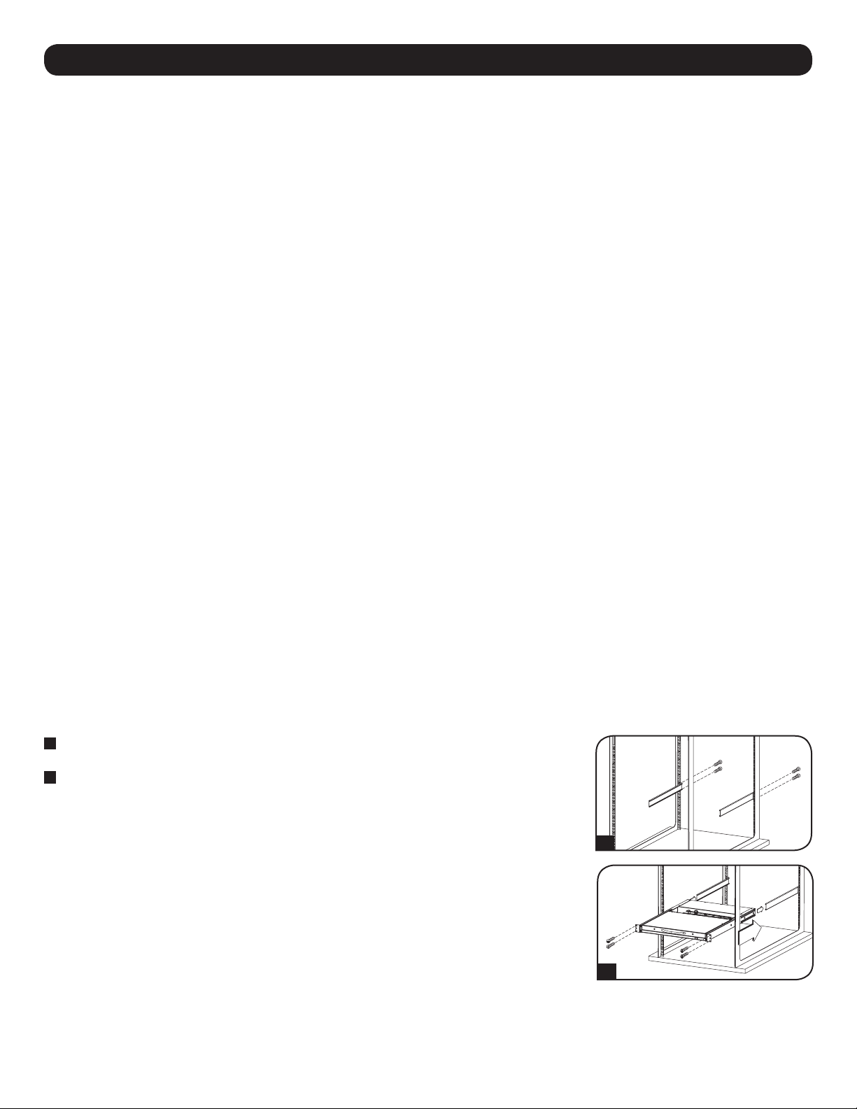
Standard Rackmounting
1
Slide out the rear mounting brackets from the console and mount both brackets (separate from the
console) to the inside rear of a standard 1U rack system using user-supplied screws.
2
Take the console and gently slide it into the two rear-mounted brackets in the rack and secure the
console in place by inserting user-supplied screws.
2-Post Rackmounting
The NetDirector Console KVM Switch can also be mounted in a 2-post rack installation using the
optional 2-Post Rackmount Kit (model #: B019-000). The mounting hardware allows for the console to
be opened with the drawer in any position. Heavy-duty, 14-gauge steel provides stability and prevents
the console frame from twisting. See the B019-000 instructional manual for detailed mounting
instructions.
1
2
7
 Loading...