

Page 1

SURVEY PRO
for Recon
GPS User’s Manual
©2004 Tripod Data Systems, Inc.
All Rights Reserved
Page 2

ii
TRIPOD DATA SYSTEMS SOFTWARE LICENSE AGREEMENT
IMPORTANT: BY OPENING THE SEALED MEDIA PACKAGE, YOU ARE AGREEING TO BE BOUND BY THE TERMS AND CONDITIONS OF
THE LICENSE AGREEMENT AND LIMITATIONS OF LIABILITY ("Agreement"). THIS AGREEMENT CONSTITUTES THE COMPLETE
AGREEMENT BETWEEN YOU AND TRIPOD DATA SYSTEMS, INC. ("Licensor"). CAREFULLY READ THE AGREEMENT AND IF YOU DO
NOT AGREE WITH THE TERMS, RETURN THE UNOPENED MEDIA PACKAGE AND THE ACCOMPANYING ITEMS (including written
materials and binders or other containers) TO THE PLACE WHERE YOU OBTAINED THEM FOR A FULL REFUND.
LICENSE. LICENSOR grants to you a limited, non-exclusive license to (i) install and operate the copy of the computer program contained in this
package ("Program") on a single computer (one central processing unit and associated monitor and keyboard) and (ii) make one archival copy of the
Program for use with the same computer. LICENSOR retains all rights to the Program not expressly granted in this Agreement.
OWNERSHIP OF PROGRAMS AND COPIES. This license is not a sale of the original Program or any copies. LICENSOR retains the ownership of
the Program and all subsequent copies of the Program made by you, regardless of the form in which the copies may exist. The Program and
accompanying manuals ("Documentation") are copyrighted works of authorship and contain valuable trade secrets and confidential information
proprietary to LICENSOR. You agree to exercise reasonable efforts to protect LICENSOR'S propriet ary interest in the Program and Documentation
and maintain them in strict confidence.
USER RESTRICTIONS. You may physically transfer some Programs from one computer to another provided that the Program is operated only on
one computer. Other Programs will operate only with the computer that has the same security code and cannot be physically transferred to anothe r
computer. You may not electronically transfer the Program or operate it in a time-sharing or service bureau operation. You agree not to translate,
modify, adapt, disassemble, de-compile, or reverse engineer the Program, or create derivative works based on the Program or Documentation or any
portions thereof.
TRANSFER. The Program is provided for use in your internal commercial business operations and must remain at all times upon a single computer
owned or leased by you. You may not rent, lease, sublicense, sell, assign, pledge, transfer or otherwise dispos e of the Program or Documentati on, on
a temporary or permanent basis, without the prior written consent of LICENSOR.
TERMINATION. This License is effective until terminated. This License will terminate automatically without notice from LICENSOR if you fail to
comply with any provision of this License. Upon termination you must cease all use of the Program and Documentation and return them, and any
copies thereof, to LICENSOR.
GENERAL. This License shall be governed by and construed in accordance with the laws of the State of Oregon, United States of America.
LIMITED WARRANTIES AND LIMITATION OF LIABILITY
LICENSOR grants solely to you a limited warranty that (i) the media on which the Program is distributed shall be substantially free from material
defects for a period of NINETY (90) DAYS, and (ii) the Program will perform substantially in accordance with the material descriptions in the
Documentation for a period of NINETY (90) DAYS. These warranties commence on the day you first obtain the Program and extend only to you, the
original customer. These limited warranties give you specific legal rights, and you may have other rights, which vary from state to state.
Except as specified above, LICENSOR MAKES NO WARRANTIES OR REPRESENTATIONS, EXPRESS OR IMPLIED, REGARDING THE
PROGRAM, MEDIA OR DOCUMENTATION AND HEREBY EXPRESSLY DISCLAIMS THE WARRANTIES OF MERCHANTABILITY AND
FITNESS FOR A PARTICULAR PURPOSE. LICENSOR does not warrant the Program will meet your requirements or that its operations will be
uninterrupted or error-free.
If the media, Program or Documentation are not as warranted above, LICENSOR will, at its option, repair or replace the nonconforming item at no
cost to you, or refund your money, provided you return the item, with proof of the date you obtained it, to LICENSOR within TEN (10) DAYS after
the expiration of the applicable warranty period. If LICENSOR determines that the particular item has been damaged by accident, abuse, misuse or
misapplication, has been modified without the written permission of LICENSOR, or if any LICENSOR label or serial number has been removed or
defaced, the limited warranties set forth above do not apply and you accept full responsibility for the product.
The warranties and remedies set forth above are exclusive and in lieu of all others, oral or written, express or implied. Statements or
representations, which add to, extend, or modify these warranties are unauthorized by LICENSOR and should not be relied upon by you.
LICENSOR or anyone involved in the creation or delivery of the Program or Documentation to you shall have no liability to you or any third party
for special, incidental, or consequential damages (including, but not limited to, loss of profits or savings, downtime, damage to or replacement of
equipment and property, or recovery or replacement of programs or data) arising from claims based in warranty, contract, tort (including
negligence), strict liability, or otherwise ev en if LICENSOR has been advised of the possi bility of such claim or damage. LICENSOR'S liability for
direct damages shall not exceed the actual amount paid for this copy of the Program.
Some states do not allow the exclusion or limitation of implied warranties or liability for incidental or consequential damages, so the above
limitations or exclusions may not apply to you.
U.S. GOVERNMENT RESTRICTED RIGHTS
If the Program is acquired for use by or on behalf of a unit or agency of the United States Government, the Program and Documentation are provided
with "Restricted Rights". Use, duplication, or disclosure by the Government is subject to restrictions as set forth in subparagraph (c)(1)(ii) of the
Rights in Technical Data and Computer Software clause at DFARS 252.227-7013, and to all other regulations, restrictions and limitations applicable
to Government use of Commercial Software. Contractor/manufacturer is Tripod Data Systems, Inc., PO Box 947, Corvallis, Oregon, 97339, United
States of America.
Should you have questions concerning the License Agreement or the Limited Warranties and Limitation of Liability, please contact in writing:
Tripod Data Systems, Inc., PO Box 947, Corvallis, Oregon, 97339, United States of America.
TRADEMARKS
Recon and Survey Pro are registered trademarks of Tripod Data Systems, Inc. Windows CE, Windows CE .NET, ActiveSync and Pocket PC are
registered trademarks of Microsoft Corporation. iPAQ is a trademark of Compaq Information Technologies Group. Bluetooth and the Bluetooth
symbol are registered trademarks of Bluetooth SIG Inc. USA. Socket is a registered trademark of Socket Communications, Inc. CompactFlash is a
registered trademark of SanDisk Corp. All other names mentioned are trademarks, registered trademarks or service marks of their respective
companies.
.MAN-RECONGPS 05032004
Page 3

iii
Table of Contents
Table of Contents................................................................................iii
Introduction ...........................................................................................5
Survey Methods ....................................................................................7
RTK and Post Processing......................................................... 8
Receiver Settings .......................................................................................8
RTK Settings.............................................................................................11
Post Processing Settings.........................................................................12
GPS Measurements.................................................................12
Differential GPS.......................................................................................12
GPS Coordinates..................................................................... 14
Projection Mode.......................................................................................14
Coordinate System Database.................................................................17
Real Time Kinematic (RTK)..............................................................19
Start GPS Survey..................................................................... 19
Start GPS Survey – Choose One Point Setup.......................................20
Start GPS Survey - Choose Projection Mode.......................................20
Start GPS Survey - Choose Base Setup.................................................21
Start GPS Survey - Connect to Receiver...............................................22
Start GPS Survey – Base Setup..............................................................22
Start GPS Survey – Rover Setup............................................................25
Start GPS Survey - Solve Localization..................................................26
Solve Localization................................................................... 26
Localization with Control Points..........................................................27
Localization Parameters Explained......................................................32
One Point Localizations Explained.......................................................37
Remote Elevation ....................................................................................39
Localization Default Zone.....................................................41
Localization Set Zone..............................................................................41
Localization Select Zone.........................................................................42
Mapping Plane Select Zone................................................... 42
Key In Zone..............................................................................................44
Mapping Ground Coordinates..............................................................46
Vertical Projection................................................................... 49
Select Geoid Model.................................................................................49
Using Ellipsoid Heights.........................................................................50
RTK Data Collection............................................................... 50
Page 4

iv
Measure Mode.........................................................................................50
Data Collection........................................................................................52
RTK Stake Out......................................................................... 57
Post Processing....................................................................................59
Field Procedure....................................................................... 59
Turn On Data Recording........................................................................59
Start Recording in Receiver...................................................................60
Data Collection........................................................................................61
Office Procedure.....................................................................62
Projection Utilities..............................................................................63
Adjust with Projection........................................................... 63
Adjust with Projection – Select Points..................................................64
Adjust with Projection – Select Coordinate System...........................66
Adjust with Projection – Prompt Adjust..............................................66
Adjust with Projection – Results...........................................................67
Projection Calculator.............................................................. 68
Scale Factor Calculator...........................................................................68
Convergence Calculator.........................................................................68
Managing GPS Coordinates with TDS...........................................69
Survey Pro ............................................................................... 69
Edit Points................................................................................................ 69
Import.......................................................................................................70
ForesightDXM and TGO........................................................ 72
ForesightDXM.........................................................................................72
TGO / TTC...............................................................................................72
GPS Coordinates.................................................................................75
Datums..................................................................................... 75
Horizontal Datums................................................................................. 77
Vertical Datums.......................................................................................79
Coordinate Systems................................................................ 81
Horizontal Coordinate Systems............................................................83
Vertical Coordinate Systems..................................................................88
Tutorial Jobs.........................................................................................91
References...........................................................................................106
Page 5

5
Introduction
This book is divided into two parts. The first part is the user’s
manual. The second part is the Reference Manual.
The User’s Manual includes an explanation of the two methods of
GPS data collection using Survey Pro: Real Time Kinematic (RTK),
and logging data for GPS post processing. This includes step -by-step
instructions on how to setup GPS equipment, select a GPS coordinate
system, solve any required coordinate system adjustment, and use
Survey Pro data collection and stake out routines. T h e ne xt section
deals with some basic fundamentals of GPS coordinate systems and
measurements. At the end of the user's manual are some tutorial
jobs you can do to illustrate the instructions in the book.
The Reference Manual contains descriptions and illustrations of
every Survey Pro GPS screen. The Reference Manual is divided into
sections based on the Survey Pro GPS menus. To find the description
of a particular screen, simply refer to the section dealing with that
menu and screen.
Page 6

Page 7

7
Survey Methods
There are two methods to collect GPS m easurements with Survey
Pro: Real Time Kinematic (RTK), and data logging for post
processing. Both methods calculate geo detic positions with a
differential GPS solution using carrier phase pseudo range
positioning. When doing RTK GPS, you will need to solve a
coordinate system in the data collect or to transform the real time
geodetic coordinates into local coordi nates for your survey. When
doing post processing, you may solve a coordinate system in the PC
software.
This section describes some basic concepts and terminology
associated with RTK and post processing data collection, as well as
the methods Survey Pro uses to calculate loca l coordinates from GPS
measurements. In this section, you will learn:
¾ How to create receiver profiles f or RTK, RTK simultaneous with
post processing, and post processing data coll ection
¾ Some basic terminology and theory required to understand GPS
measurements.
¾ A description of the different GPS solution types, and the
expected precision of each one.
¾ A description of the horizontal and vertical projec tion modes used
by Survey Pro to transform geodetic position into local
coordinates.
¾ A description of the coordinate system database used by Survey
Pro.
Page 8

Survey Pro GPS User’s Manual
8
RTK and Post Processing
Using GPS for precise survey measurements requires data fro m two
receivers to be collected simultaneously. There are two common
methods for calculating positions with this data: Real Time
Kinematic (RTK) and post processing. In an RTK survey, one
receiver acts as a base station, collecting GPS measurements and
broadcasting the raw data over a modem link such as a radio or cell
phone. The other receiver acts as a rover, receivin g the base data and
combining it with its own measurements for a re al time solution of
position at the rover. In a post processing survey, two or more
receivers log raw GPS measurements simultaneously to a file in the
field. Then, the data is downloaded onto a computer where the
differential solution is calculated ( post processed) after the field data
collection is completed.
Survey Pro can control GPS receivers for RTK, RTK simultaneous
with post processing, and post processing only data collection. Before
you can start any GPS survey, you must create a receiver profile for
any receiver you will be using.
Receiver Settings
Using either RTK or post processing data co llection is controlled by
the type of receiver you choose to connect to. The Job
| Settings |
Receiver
screen is used to manage receiver profiles for RTK an d post
processing receivers. You must create a receiver profile for each
different brand and model you want to use as either an RTK base,
RTK rover, or post processing only receiver.
Page 9

Survey Methods
9
Receiver Settings Receiver Setup
1. Go to the Job
| Settings | Receiver and tap Receiver Settings to
open the Receiver Setup screen. Alternatively, you can tap
Create Receiver or Receiver Settings when prompted to connect to
a receiver during Start GPS Survey (Page 22).
2. Enter a Name for this receiver profile, choose the Brand and
Model, and select the communication settings.
3. Tap Rx Settings to connect to the receiver and set the receiver
profile’s properties.
4. Choose a Receiver Mode for this profile. This will be one of: RTK
Base, RTK Rover, or Post Processing.
5. If this profil e is for an RTK receiver, set data link settings on the
Rx Settings – Data Modem card. Also, if your receiver has special
settings, choose the desired parameters on the General card.
6. Tap OK to close the Rx Settings
screen, and OK again to create or
update the receiver profile.
This receiver profile is now ready to use in a GPS survey. You should
now set the RTK and/or post processing settings on the following
cards of the Job
| Settings screen
Page 10

Survey Pro GPS User’s Manual
10
Bluetooth Communication
Survey Pro can communicate wirelessly with a supported receiver
using a Bluetooth connection when the following conditions are met:
• A Socket™ Bluetooth Compact Flash card and its drivers are
installed on the Recon data collector.
• The receiver has Bluetooth built in and is expl icitly supported
by Survey Pro.
Note: Refer to the Bluetooth section of the con ventional surveying
User’s Manual for detailed instructions on con fi guring the Bluetooth
drivers for use with Survey Pro.
Using Bluetooth in Survey Pro
Once the Bluetooth device and drivers are inst alled on the data
collector, you can use Bluetooth to communicate with the receiver. To
configure Bluetooth communications.:
1. On the Job
| Settings | Receicer | Receiver Setup screen, set the
data collector port to Bluetooth.
2. Tap Settings to open the Bluetooth Devices
control panel
application, described in the User’s Manual, where you can scan
for Bluetooth receivers, assign a Bluetooth receiver as your
‘favorite’ device, or change the Bluetooth com port assignments
for different devices.
Bluetooth Limitations
Bluetooth can be thought of as a short-ran ge radio link. As with any
radio link of this type, communications can be interrupted by a
number of reasons, including, but not limited to:
• The operating range between the d evices is exceeded. (The
Bluetooth range is limited to approxim ately 10 meters.)
• Another powerful radio signal is broadcast near an active
Bluetooth device.
• An object, such as your body, physically blocks the radio
signal.
Page 11

Survey Methods
11
If the Bluetooth signal is lost, move the data collector closer to the
receiver or try to eliminate the sourc e of i n terference. The connection
will then usually be reestablished automatically.
Note: The operating system resets the Bluetooth connection after the
data collector is powered on. If the data collector is powered off while
using Bluetooth, you should wait at least 10 seconds after powering it
back on before using any function where Bluetooth communication
will occur. This is to allow enough time for the Bluetooth connection
to reset.
Warning: It is not recommended that Bluetooth communication be
used while logging GPS data to use for post processing. This scenario
requires constant and reliable communications between the data
collector and the receiver so a cable shoul d be used for
communication.
RTK Settings
If you are using Survey Pro for RTK, or RTK simultaneous with post
processing data collection, the foll owing cards of the Job
| Settings
screen are used:
• Measure Mode
: is where you select the receiver dynam ic f or po int
occupations and the type of GPS raw data to store for each point.
You can also set measurement acceptance criteria. These settings
are described in detail in the Reference Ma nual.
• Projection
: is where you set your horizontal and vertical
projection type and specify the path to ge odetic data files. These
settings are described in detail in the Reference Manual.
Page 12

Survey Pro GPS User’s Manual
12
Post Processing Settings
If you are using Survey Pro for RTK simultane ous with post
processing, or post processing data collection, the Post Process
card of
the Job
| Settings screen applies.
Post Process
: is where you turn on post processing data collection by
specifying a Recording Interval for the receiver’s internal memory.
You can also specify how to deal with autonomous positions and
select a special layer to store autonomous points o n. These settings
are described in detail in the Reference Ma nual.
GPS Measurements
Differential GPS
GPS coordinates are computed using pseudo- r ange positioning.
Pseudo-range positioning invol ves intersecting the ranges from the
known SV position in a manner similar to a distance – distance
intersection problem. Four SVs are required to determine three
position dimensions and time. Position dimensions are computed by
the receiver in Earth-Centered, Earth-Fixed X, Y, Z (ECEF XYZ)
coordinates.
A pseudo-range solution will b e one of two types: autonomous, or
differential. A single GPS receiver can compute an autonomous
position from ranges to four or more SV. This single receiver position
is extremely coarse. One can expect errors in the order of 100-m on a
bad day. For this reason, precise GPS measurements must be
performed using differential positioning.
Differential GPS (DGPS) positionin g involves subtracting a
combination of ranges measured to various sat el li tes from two or
more receivers. When the signals are subtracted, the major error
sources cancel each other out. However, because you are computing a
difference in ranges, the DGPS measurement solves for a coordinate
difference and not a coordinate. To compute a coordinate using a
coordinate difference, you must first specify a starting point. In RTK
Page 13

Survey Methods
13
survey, this starting point is the reference position the base receiver
broadcasts over the data link. In a post processing survey, this
starting point is specified by the user in the processing so ftware.
Differential Solutions: Types and Quality
A differential GPS solution can calcula t ed using either the GPS code
data, or the GPS carrier phase wave. A carrier phase solution can be
calculated from either float ambiguities or fixed ambiguities. An
explanation of these terms, and the ex pected precision from the
different solution types is explained below.
Code Differential
Code differential solutions use the Coarse Acquisition (C/A)
navigation code transmitted on the GPS carrier wave. Because the
wavelength of the code segment is long (300m), code differential is the
least precise differential soluti on. Accuracies of 1-10 meters are
possible with DGPS using C/A code differential positioning.
Carrier Phase Differential
Highly precise coordinate differences can be measured using pseudorange positioning with the carrier signal wa ve. Because the
wavelength of the carrier wave is only 19 cm, mm level positioning is
possible. When the signal arrives at the antenna, you can measure
the fractional part of the carrier wave. If you can then calculate the
whole number of wavelengths between the SV and the antenna (the
ambiguity), you can add it to the fractional part and multiply by the
length of one cycle to measure a precise range.
Calculating the exact number of wavelengths uses a complicated least
squares process, which is often called ambiguity resolution. The
ambiguity resolution will yield either a float or a fixed solution.
• Fixed Solution
You know the number of wavelengths will be a whole number.
Techniques are used to constrain the least squares solution to yi eld a
whole number. If you get an acceptable solution, you say that this
solution is fixed. A fixed solution will gen erate coordinate differences
precise to about 15-ppm (single fr equency) or 5-ppm (dual frequency),
which translates into 15-mm or 5-mm over a 1-km base line.
Page 14

Survey Pro GPS User’s Manual
14
Several things may prevent you from achieving a fixed solution : bad
multi-path, low number of satellites and bad constellation geo metry,
poor radio link for corrections (RTK).
• Float Solution
If the constraint algorithm does not produce an acceptable fixed
solution, then the ambiguity is allowed to be a decimal (float)
number. A float solution will generate coordinate differences precise
to about 100 to 500-ppm, which translates into 0.1-m to 0.5-m over a
1-km base line.
GPS Coordinates
GPS positions are measured in a 3D coordinate system which models
the earth using an ellipsoidal shape. The horizontal position is
usually given as two angles, relative to the el lipsoid axes, called
latitude and longitude. The vertical position is usuall y given as a
linear distance, perpendicular to the ellipsoid, called height. Most
survey projects use horizontal coordinates on a plane which
approximates a small piece of the gr o und assuming a ‘flat earth’. The
horizontal position is usually given as two linear distances, called
northing and easting. The vertical position is usually given as a
linear distance, describing the direction water will flow down hill,
called elevation. The usual method t o convert latitude, longitude and
height to northing and easting is to use a map projection. The usual
method to convert height to elevation is to use a geoid model.
Projection Mode
Survey Pro has two different modes for calculating local northing and
easting from GPS measurements: Grou nd – TDS Localization, and
Mapping Plane. Survey Pro has two different modes for calculating
the vertical coordinate from GPS measured heights: Localization
(+Geoid) and Ellipsoid Heights.
In Ground - TDS Localization mode, the is no map projection and no
datum to transform geodetic to local coordinates. In this case, a
default map projection is created with the f irst RTK base setup.
Then, a localization adjustment is solved (Page 26). The localizat io n
Page 15

Survey Methods
15
adjustment is a 2D similarity transformation that shifts, scales, and
rotates the default map projection’s locations (y,x) into your local
coordinates (N,E). In Ground - TDS Localization mode, when you
measure a distance with an EDM, the distance measured on the
ground is 1:1 with the distance on the loc al coordinate grid.
In Mapping Plane mode, there is a specified conformal map projection
and geodetic datum to transform geodetic to local coordinates. In this
case, you select the coordinate system from the database file (Page
42). This mapping plane and datum is used to calculate northing and
easting from latitude, longitude and height. coordinates If you set
your RTK base on a point with known coordin ates, then no additional
steps are required to solve the coordinate system. If you set your
RTK base on an unknown point, then you can solve a localization
adjustment to correct the positions to the prop er local coordinates
(Page 26). In Mapping Plane mode, when you measure a distance
with an EDM, the distance measured on the ground is not usually 1:1
with the distance on the mapping plane grid. In this case, you must
usually use a combined scale factor (Page 85).
In either horizontal projection m ode, you can choose one of the
vertical modes. Use Localization (+Geoid) mode when you want the
local vertical coordinate to be orthometric elevations, and height is
adjusted to an elevation datum. Use Ellipsoid Heights mode when the
vertical coordinate does not need to be elevations, and the unadjusted
local ellipsoid height is used.
Projection Mode Summary
Horizontal Projection Modes
Ground - TDS Localization
• Local coordinates are at ground level, based on the project
height.
• Distances shot with EDM are at ground scale, so are 1:1 with
coordinates solved by the projec tion.
• Default map projection and datum are automatically
initialized with RTK base setup.
Page 16

Survey Pro GPS User’s Manual
16
Mapping Plane
• Local coordinates are on a conformal m ap projection grid.
• Distances shot with EDM are usually scaled by the combined
scale factor to distances on the map project io n grid.
• User selects map projection zone.
Vertical Projection Modes
Localization (+Geoid)
• Vertical coordinate is orthometric e levation.
• User must solve transformation from ellipsoid heights to
elevations. This is done with localization on control poi nts, or
using a geoid model, or a combination of both.
Ellipsoid Heights
• Vertical coordinate is ellipsoid heigh t .
Ellipsoid Heights mode requires no transformation setup. Use this
mode when vertical coordinates do not need to be elevations.
Coordinate System Set or Solved
There can be multiple steps required before your coordinat e system is
ready to transform geodetic positions into local coordinates. The
status of your coordinate system may be in one of three states: uninitialized, set, or solved.
A coordinate system is un-initialized when y ou have no zone record
set. In Ground – TDS Localization mode, this means that you have not
yet configured the first RTK base position in Survey Pro. In Mapping
Plane mode, this means you have not yet selected a zone record from
the coordinate system database.
A coordinate system is set when there is a zone record set. In Ground
- TDS Localization mode, a default mapping plane zone is set when
you configure your first base reference position for the job. In
Mapping Plane mode, you select a zone from the coordinate system
database.
A coordinate system is solved when it is ready to correctly transform
GPS positions measured at the rover into your loca l coordinates. In
Page 17

Survey Methods
17
Ground – TDS Localization mode, this is the case after you have solved
the horizontal localization adjustment. In Mapping Plane mode,
there are two cases. When you start a survey from a known base
position, then the rover is already calculating accurate positions, and
the coordinate system is set and solved. When you start a survey
from a new autonomous base position, you must solve a horizontal
adjustment from control points before you are ready to collect data.
Coordinate System Database
Survey Pro uses a Coordinate System Database file (*.CSD) to store
the map projection and datum transformation parameters for many
different coordinate systems around the world. Also, horizontal and
vertical localization adjustments can be stored as site records in the
database. Below is a list of the terminology used to describe the
different records in the coordinate system database.
• Zone: Is the basic record type. A zone record specifies the type of
map projection and its parameters. Usually there is a datum,
ellipsoid, and geoid record from the database already attached to
the zone.
• Site: Is a zone record with a horizontal and/or vertical
localization adjustment added. Localizations are usually used to
correct GPS positions starting from an autonomous base. They
can be computed from control points or from manual input of
parameters. Coordinate systems with Ground Coordinates set
are also site records. A Ground Coordinates site record may or
may not have a horizontal and/or vertical localization adjustment.
• Zone Group: Is a collection of zone and/or site records used to
keep the database organized and user selection easier.
• Datum: Is a type of datum transformation and its parameters.
There is always an ellipsoid record from the database alread y
attached to the datum.
• Ellipsoid: Are the two par ameters specifying the ellipsoid of the
datum.
• Geoid: Is a geoid model and its associated data file.
Page 18

Page 19

19
Real Time Kinematic
(RTK)
RTK data collection uses differentia l GPS corrections broadcast by a
base receiver to solve for coordinates at a rover receiver in real time.
This section describes how to start a GPS survey and how to use GPS
data collection and stake out. In this section, you will learn:
¾ How to start an RTK, or an RTK simultaneous with post
processing survey.
¾ How to select a projection mode to con vert geodetic positions
(latitude, longitude, height) to your local coordinates
(Northing, Easting, Elevation).
¾ How to set up the RTK base receiver and configure the base
reference position.
¾ How to set up the RTK rover receiver.
¾ How to solve a horizontal and vertical localization coordinate
system adjustment, and when a coordinate system
adjustment is required.
¾ How to switch between grid and ground coordinates when
surveying on a selected mapping plane.
¾ How to collect data with GPS.
¾ How to stake out with GPS.
Start GPS Survey
The Start GPS Survey wizard is used to start any RTK survey. This
wizard will guide you through the steps required to choose a
coordinate system, set up your equipment, sol ve an adjustment, and
start collecting data or staking out points. The Start GPS Survey
wizard can be used for any RTK setup, regardless of your coordinate
system requirements, and your base and rov er equipment
configuration.
The steps required to complete the Start GP S Survey wizard will
depend on the coordinate system and equipment you are using. All
the possible steps are described below.
Page 20

Survey Pro GPS User’s Manual
20
Start GPS Survey – Choose One
Point Setup
One point setup is a special case of the Start GPS
Survey wizard. You can use one point setup mode only
when you have a brand new job with only one po int.
When you use one point setup, Survey Pro will use
Ground - TDS Localization mode, and automatically solve
the localization adjustment to give you ground level
coordinate system with the origin at your first point.
When you choose one point setup, there are no
additional steps required to solve your coordinate
system, all you have to do is complete base and rover
equipment setup and you are ready to survey.
Start GPS Survey - Choose
Projection Mode
The Start GPS Survey Choose Projection mode screen is used to
choose the horizontal projection mode. There are two choices:
Choose to Use Ground – TDS Localization when your
survey is a ground level site with no projection and no
datum to relate the local coordinates to geodetic. When
you choose Ground – TDS Localization, the next step will
be base and rover setup, and solving the localization
adjustment.
Choose to Select a Mapping Plane Zone when your survey
coordinate system is a conformal mapp ing plane defined
in the coordinate system database. When you ch oose
Mapping Plane mode, your next step will be to select a
coordinate system from the database (Page 42). Then,
you will proceed with base and rover setup. If you set
the base on a known point, you do not need a
localization adjustment and you will be ready to collect
data after rover setup. If you start from an autonomous
base, you must solve a localization adjustment.
Page 21

RTK Data Collection
21
Start GPS Survey - Choose Base
Setup
The Start GPS Survey Choose Base Setup screen is used to select how
you will set your GPS base. There are three choic es:
• Use Current Base: This option can be used when you
have already set a base station with this data
collector. When you tap Use Current Base, the Start
GPS Survey wizard will display the next screen
required for setup . This will be either the Rover
Setup screen, the Start GPS Survey – Solve
Localization screen, or, if the complete setup is
already done, the Data Collection
screen (Page 50)
will be opened.
• Set New Base: This option is used when you wish to
connect to a GPS base receiver, set it as an RTK base,
and configure the base reference position in Survey
Pro. When you select Set New Base, the Base Setup
wizard is opened .
• Use Remote Base: This option is used when there is already a
base set up and broadcasting corrections. Choose t h is option to
setup a rover receiver and configure the base position in Survey
Pro. When you select Use Remote Base, the Rover Setup
screen is
opened.
Page 22
Survey Pro GPS User’s Manual
22
Start GPS Survey - Connect to
Receiver
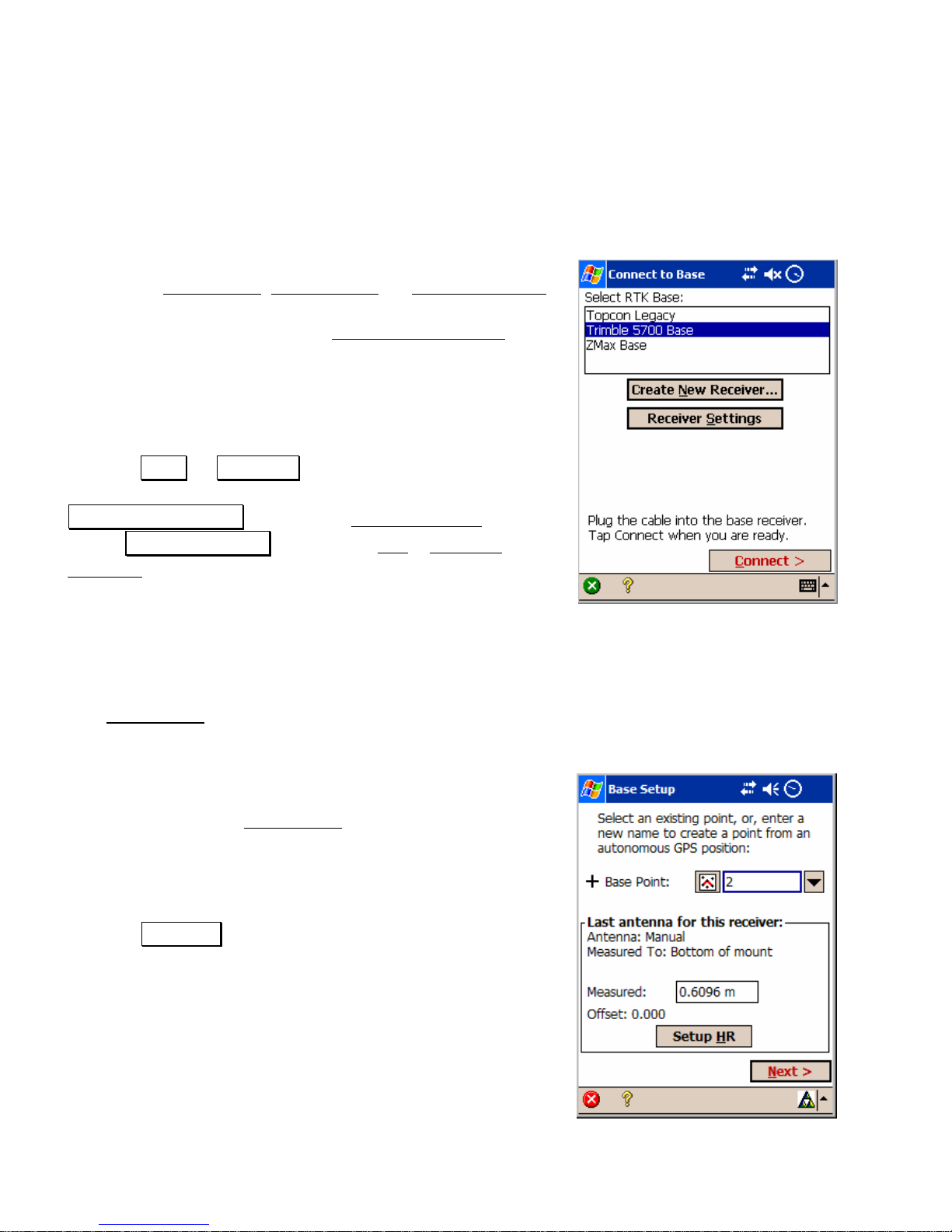
Before the Base Setup, Rover Setup, or Data Collection
screens are opened, you will be prompted to connect to
the appropriate receiver. The Connect to Receiver
screen is used to display a list of all of the receivers of
the appropriate type (base, rover, or post proc essing) you
can connect to. If you have used this type of equ ipment
with this data collector before, then the receiver you last
used is remembered and you can proceed simply by
tapping Enter or Connect>. If you need to create a new
receiver or change the receiver settings, you can tap
Create New Receiver to open the Receiver Setup
screen,
or tap Receiver Settings to open the Job | Settings |
Receiver screen (Page 8).
Start GPS Survey – Base
Setup
The Base Setup wizard is used to setup an RTK base receiver, and to
configure the base reference position in Survey Pro.
Base Setup One – Pick Point
The first step of the Base Setup wizard is to pick a point
for the base reference position, and measure th e
antenna height at the setup.
1. Set the base receiver antenna over the point.
2. Tap Setup HR to select your antenna type and
measure the slant or vertical height of the antenna.
3. Enter a name for the Base Point. You can select an
existing point from the job or you can ent er a ne w
point name for the job. If you select:
Page 23

RTK Data Collection
23
• An existing point with geodetic coordinates, the GPS base
receiver is set with this coordinate, and the base reference
position is configured in Survey Pro.
• An existing point with plane only (N,E,Elev) co ordinates when
the coordinate system is solved, the pl ane coordinate is
transformed into geodetic, the GPS base rec ei ver is set with this
coordinate, and the base reference positio n is configured in
Survey Pro.
• A new point, or, an existing plane point when no projection is
solved, you start from an autonomous position. You will GET an
autonomous position from the GPS receiver for your first base
setup. You then SET this reference positi on in the GPS receiver
and configure the base position in Survey Pro.
Note: It is strongly recommended that you use only one autonomous
GPS base position in a job. If you must use multiple autonomous
setups in a single job, you will be prompted to setup and select a
separate site record for each setup group.
4. Tap Next>.
The final step of the Base Setup wizard will depend on the base point
chosen. If the base (lat, lng, ht) is known or can be computed, the
final step is to SET the base at the known geodetic position. If the
base (lat, lng, ht) is not known, the final step is to GET an
autonomous position to SET the base with.
Page 24

Survey Pro GPS User’s Manual
24
Base Setup Two – SET
The Base Setup Set screen is used when the geodetic coordinate of the
chosen base reference point is known or can be calculated.
5. Tap SET to start the base receiver broadcasting this
reference position and GPS observations over the
radio link, and to configure the base reference
position in Survey Pro.
Note: If you have post processing data collection turned
on, the receiver will now open a file (with the next
available default name), start recording GPS raw data,
and record the station and antenna information for this
static session.
Base Setup Two - GET and SET
The Base Setup GET and SET screen is used when the geodetic
coordinate of the base reference position is not known. In this case,
you must GET an autonomous position from the GPS receiver, then
you can SET this as the reference position.
5. Tap GET Position From Rx to get an autonomous
position from the receiver. If you wish to get an
averaged position, enter a number in Average
position [n] epochs before GET.
6. Check the r e sults displayed in the edit boxes. If it
looks good, tap SET to start the base receiver
broadcasting this reference position and GPS
observations over the radio link, and to configure
the base reference position in Survey Pro.
Page 25

RTK Data Collection
25
Note: If you have post processing data collec ti on turned on, the
receiver will now open a file (with the next available default name),
start recording GPS raw data, and record the station and antenna
information for this static session.
Start GPS Survey – Rover Setup
The Start GPS Survey Rover Setup screen is used to setup an RTK
rover receiver, and to configure or check the base point reference
position in Survey Pro.
1. Tap Setup HR to select your antenna type and
measure the slant or vertical height of the antenna.
2. Tap SET Rover to setup the receiver as an RTK
rover. The rover will then wait to receive the base
reference position over the data mod e m link. If you
have already configured the base with this data
collector, then the base reference position from
Survey Pro will be checked against the positi on
received at the rover. If you have not yet configured
the base reference position in Survey Pro, it will be
configured with the position received at the rover.
Note: If you have post processing data collec ti on turned on, the
receiver will now open a file (with the next available default name),
start recording GPS raw data, and enter the antenna information for
this stop and go session.
Page 26

Survey Pro GPS User’s Manual
26
Start GPS Survey - Solve Localization
The Start GPS Survey Solve Localization screen is
displayed when you need a horizontal adjustment to
solve your coordinate system. A horizontal adjustment
is required to solve your coordinate system any time you
begin a survey from an autonomous base position. This
is always the case when your projection mode is Ground
– TDS Localization, since your first base setup is always
from an autonomous GPS position. This may be the
case when your projection mode is Map ping Plane, when
you set your first base on a new point. A vertical
adjustment is often desired, although not required
before data collection can begin.
The horizontal and vertical adjustments are usually
solved together. First, tap Collect Control> to occupy
some existing local points as GPS Control points. Next,
tap Solve Localization … to open the Solve Localization
wizard to
calculate the horizontal and vertical adjustment parameters (Page
27).
After you successfully solve the localization adjustment, the Start
GPS Survey wizard will close, and the GPS Data Collection screen
will open (Page 50). You are now ready to measure and store new
points in this job.
Solve Localization
When you start a GPS survey from an autonomous base position, you
need to solve a localization to adjust GPS measurements into local
coordinates. This is the case for both horizontal projection modes.
Using Ground - TDS Localization, you need to solve a localization to
relate your arbitrary GPS start point into your non-geodetic local
system. Using a Mapping Plane, you need to solve a localization to
shift the autonomous GPS start point into accurate geodetic
coordinates.
Page 27

RTK Data Collection
27
In either horizontal mode, the procedure is the same. Starting from
an autonomous GPS base setup, you measure GPS positions on
control points with know local p lane (N,E) coordinates. The
parameters for a 2D similarity transformation are calculated with a
least squares solution using the control points. These parameters are
added to the zone record (the default Ground - TDS Localization mode
zone or the selected Mapping Plane mode zone) to create a zone based
site record.
Vertical localization, with or without a geoid model, uses the same
field procedure. Starting from an autonomous GPS base setup, you
measure GPS positions on control points with know local elevations.
The vertical adjustment parameters are calcu lated from the control
points. The vertical adjustment will be either a shift to correct geoid
elevations to local elevatio ns, or an inclined plane to correct for
vertical shift and tilts.
Note: If you are starting a new job from an autonomous GPS base
setup using one point setup, you do not need to solve a localization
adjustment. The default map projection will be scaled to ground, and
oriented with grid north equal to geodetic north at your first base
station.
Localization with Control Points
Horizontal localization is a simple 2D similarity transformation from
mapping plane coordinates in an intermediate system to coordinates
in your local system. In Ground - TDS Localization mode, the
intermediate system is the default ma p projection initialized for
ground distances at the base height. In Mapping Plane mode, the
intermediate system is the inaccurate coordinates calculated on the
selected map projection from the autonomous GPS base.
Vertical localization is a correction from measured ellipsoid heights or
geoid elevations calculated from heights, into local elevations. This
correction can be a simple shift or a three-parameter inclined plane.
Page 28

Survey Pro GPS User’s Manual
28
Localization with Control Points: Summary
¾ Take GPS measurements to at least the minimum number of
control points. In Ground – TDS Localization mode, at least
two horizontal control points are required. In Mapping Plane
mode, at least one horizontal control point is required. In
Localization (+Geoid) mode at least three vertical control
points are required when there is no geoid model, and one
vertical control point is required when ther e is a geoid model.
¾ Tap Solve Localization… to open the Solve Localization
wizard.
¾ Select the points to use for horizontal and vertical control and
tap Solve>.
¾ Verify solution residual or misclosure quality. Tap Next> to
review the parameters and tap Accept to finish setup.
¾ Occupy additional local points as check points to verify
solution quality. If desired, additional points can be added as
control points and included in solution.
Note: When you resolve the localization, all of your job file points
will automatically be readjusted using the Adj u st with P r ojection
wizard (Page 63). Therefore, your local coordinates derived from GPS
measurements will always be calculated using the latest coordinate
system solved.
Detailed Procedure
Since the field procedure is the same fo r both horizontal
and vertical localization solutions, the instructions below
cover both cases.
1. From the C ontrol Points
screen, select a control point
to occupy and enter the name into the Point control.
Horizontal control points must have a valid northing
and easting coordinate in the local system . Vertical
control points may have a valid horizontal coordinate
(although it is not used in the calculation) but must
have a valid elevation.
Page 29

RTK Data Collection
29
Note: If Store GPS Raw Data on the Measure Mode card of the Job,
Settings screen is set to EP + Rx Raw (or + OBN for Ashtech users),
when you begin a point occupation the control point name is checked
as a valid site ID for the receiver. If it is not a valid site ID, Survey
Pro will use a modified point name in the receiver’s internal file and
make a note of the modified name in the job’s .RAW file. The point
name in Survey Pro is not changed.
2. Level the ro ver antenna over the point and tap Control Point to
begin data collection.
3. When you are happy with the measurement, tap Accept.
4. Check the Results tab for details of the previous measurement.
Check the Map
tab to see the number and position of contr ol
points for this set up group.
5. Collect a m inimum of one control points to solve horizontal
localization on a mapping plane. Collect a minimum of two
control points to solve a horizontal localization in an arbitrary
ground system with no projection and no datum. Collect a
minimum of three vertical control points to solve vertical
localization. Collect one vertical contr ol point to solve just the
localization vertical shift when using a geoi d m odel.
6. When you have collect ed t he minimum number of control points,
tap Projection and Solve Localization to open the Solve
Localization wizard.
Note: If you are using localization for the vertical transform mode,
then the next screen will look like the illustration below. If you are
using ellipsoid heights, then the vertical colum n will be missing.
7. In the list box, control points collected will be identified with an H
and/or V. Points marked H will be used to solve horizontal
localization. Points marked with a V will be used to solve vertical
localization. You can select or deselect any point by highligh ting
Page 30

Survey Pro GPS User’s Manual
30
that point and then: tap the H and/or V column beside that point;
press H and/or V on the keyboard.
Note: If your base was set up on a known point, that point is an
eligible control point. If your base was set up on a new point, then it
is not visible on the control point list.
8. If you wish to hold the scale of the GPS
measurements, but you want the localization
adjustment to correct for a rotation, check the Solve
Rotation Only control in the Fix H Scale to 1.0 box.
9. Double check the selection of control points and tap
Solve >. The localization parameters are computed
using the selected control points, and the next
screen is opened with solution RMS values.
10. For both horizontal and vertical, the solution type
and RMS value from the control points are
displayed. The solution type will be one of:
• Unique: the solution was calculated using the
minimum number of control points or fewer. In
this case, there is no least squares solution to
provide residuals, so the numbers in the N Err, E
Err, and/or V Err columns are misclosures
calculated from the control points that are not
used in the solution.
• LSQ: the solution was calculated with more
than the minimum number of control points. In
this case, the least squares solution can produce
residuals, and the N Err, E Err, and/or V Err
columns show residuals for the points that are
used in the solution.
11. If you are not happy with the solution residual or
misclosure values for any point, you can change the
control points used by tapping in the H and/or V columns. This
Page 31

RTK Data Collection
31
will change Next> to Solve>. Tap Solve> to recalculate the
solution and update the residual / misclosure display.
12. When you are happy with the solution quality, tap Next> to
review the parameters.
13. Examine the scale and rotation values to ver ify they are
reasonable. See the explanation of l ocalization parameters (Page
32) to determine what is reasonable.
14. When you are happy with the solution, tap Accept to set the
horizontal and/or vertical adjustmen t. The Adjust with Projection
wizard will open to show you a preview of the chan ges to the
geodetic points. Tap Accept to update the coordinate system in
the job and raw data, and to apply the adjustment to the points.
Manual Entry of Parameters
Manual entry of parameters is used when you alre ady know the
appropriate horizontal and vertical localization parameters for a site.
Use manual entry of parameters to key in the site parameters and set
it as the current coordinate system.
1. Tap Solve Localization to open the Solve Localization
wizard and
then tap Manual Entry>.
Page 32

Survey Pro GPS User’s Manual
32
2. Enter the Scale, Rotation, Translations, and Origin of the
horizontal system.
3. Enter the Slope N, Slope E, Separation, and Origin of the vertical
adjustment.
4. Tap Solve> to show the horizontal and vertical parameters
entered.
5. Review th e results and tap Accept when you are done.
Localization Parameters Explained
Before you accept a localization solution, you should evaluate the
parameters and the quality of the solution. This section describes the
meaning and the expected values for the six horizontal and five
vertical localization parameters. Guidelines for the quality and
geometry of control points plus the soluti on redundancy and residuals
are also described.
Horizontal
Ground - TDS Localization Mode:
Scale: is the scale difference between the int ermediate mapping
plane and the local system. Scale should b e very close to 1.0. A value
of 1.0 corresponds to ground level distances at the base reference
height.
Scale values are often reduced to parts per million in order to relate
the factor to a distance. One ppm (the sixth decimal place i.e.
1.000001 or 0.999999) is equal to 1mm in 1km. This is well below
RTK precision. Fifteen ppm (1.000015 or 0.0.999985) is equal to
15mm in 1km. This is a usual RTK precision, so anything in this
range is expected. A scale value significantl y greater or smaller than
1.0 may indicate problems with the control point accuracy and/or the
control measurement precision. It might also indicate a base
reference height too high or low for the survey area, or a scale bias in
the control point local coordinates.
Rotation: is the rotation between the localization map projection
zone and the local system. The rotation represents the difference
between grid north and geodetic north at the meridian passing
Page 33

RTK Data Collection
33
through the origin of the localization transformation. Because most
local coordinate systems are not referenced to a geodetic azimuth, any
number could be a valid parameter here.
Origin: is the coordinate on the intermediate mapping plane of the
centroid of the control points. It is calculated by average of the
mapping plane (y,x) coordinates of all control points.
Translation: is the shift from the Origin to the centroid of the
control points in the local coordinate system.
Mapping Plane Mode:
Scale: is the scale difference between the int ermediate mapping
plane using the autonomous GPS position and the actual mapping
plane control coordinates. Scale should be v ery cl ose to 1. 0. A value
of 1.0 corresponds to grid distances on the selected conformal
mapping plane.
A scale value significantly greater or smaller than 1.0 may indicate
problems with the control point accuracy and/or the control
measurement precision. It might also indicate a scale bias in the
control point plane coordinates, which you may want to correct by
solving a fixed scale transformation.
Rotation: is the rotation between intermediate mapping plane using
the autonomous GPS position and the actual mapping plane. The
rotation should be very close to 0.0. A rotation value si gnificantly
greater or smaller than 0.0 may indicate problems with the control
point accuracy and/or control measurement precision. It might also
be an orientation bias of the mapping plane control system that you
wish to solve for.
Origin: is the coordinate on the intermediate mapping plane of the
centroid of the control points. It is calculated by average of the
mapping plane (y,x) coordinates of all control points.
Translation: is the shift from the Origin to the centroid of th e
control points in the local coordinate system. This value represents
the shift introduced by the inaccurate autonomous GPS starting
position, and is usually less than 10m, the accuracy of an autonomous
GPS position.
Page 34

Survey Pro GPS User’s Manual
34
Vertical:
Slope: is the North and East tilt of the inclined plane adjustm ent.
These values are given in parts per million, and re present the radian
angle values of the deflection between the ellipsoid normal and the
local gravity vector. This tilt approximates what a geodosist would
call 'deflection of the vertical'.
Separation: is the shift between the local elevation and the vertical
reference surface (geoid elevations when using a geoid model or
ellipsoid height when using localization vertical only).
Origin: is the local coordinate of the first point used in the control
point list. The slope values are appli ed from this point.
Vertical Calibration and Geoid Modeling
If you do not use a geoid model, vertical localizati o n will solve for
slope and separation using the measured heights and the control
elevations. If you do use a geoid model, vertica l lo calization will solve
for the separation between the geoid elevation and your control
elevation. Geoid elevations are computed from measured heights and
geoid undulation using the heigh t equation (see page 88):
h = H + N
Fig. 9: Vertical Localization
Three control points calculate a plane to model the deflection and shift
between the geoid and ellipsoid surface.
E
l
l
i
p
s
o
i
d
S
u
r
f
a
c
e
G
e
o
i
d
S
u
r
f
a
c
e
Separation
Normal
to Geoid
Normal to
Ellipsoid
Deflection (a,b)
Page 35

RTK Data Collection
35
Quality of Localization Solutions
Starting from an autonomous GPS base position and solving a
localization with control points is similar t o start ing a conventional
survey from an unknown setup and solving a resection. The quality
of the solution depends on both the precision o f the measurements to
the control points and the accuracy of the control point coordinates.
When solving a localization with control points, the following
guidelines should be followed:
• Quality of control points: the control point coordinates should be
at least as precise as the specified surv ey requirements.
• Geometry of control points: the control points should be
distributed evenly surrounding the survey area.
The illustration on the left shows an example of poor GPS
control point geometry. The points do not surround the
survey area, and they are nearly co-linear, which is a big
problem for the vertical adjustment. The illustration on the
right shows an example of good control po int geometry. The
points surround the survey area, and form a nearly
equilateral triangle for the vertical solution.
Poor Control Point Geometry Good Control Point
Page 36

Survey Pro GPS User’s Manual
36
• Check points: after solving for localization parameters with a
minimum number of control points, you should occupy an
independent checkpoint to verify the solu tion quality. If you
desire, this point can be added as a control point and used for
subsequent solutions. If the checkpoint measurem ent is within
the tolerance, this step should not be necessary.
• Redundancy and residuals: After solving localization parameters
with more than the minimum number of control points, you
should examine the solution residuals. The residuals should be
close to the measurement precisio n of your instrument and the
control points.
Ground - TDS Localization Explained:
When the horizontal projection mode is Ground - TDS Localization, a
default map projection is automatically set up to produce ground
coordinates at the base station height. The Ground - TDS Localization
mode default map projection is an obl ique stereographic map
projection with the following parameters:
o Origin is at the initial base station location
o False northing and false easting of 100000.0 m
o Scale at the origin of the stereographic m ap projection zone is
calculated to produce ground scale distances at the height of
the first GPS setup. This projection scale factor is simpl y the
inverse of the ellipsoid scale factor for the reference height
(see page 85).
Origin Scale (k
map
) = (R+h)/ R
2
1
22
)sin1(φe
a
R−=
Localization Setup Groups
When you set up different base stations with autonomous positions
from a GET, each position is only accur ate to +- 30m (+- 10 m with
Selective Availability (SA) turned off). Geodetic coordinates
measured from your first autonomous base will not be accurately
connected to geodetic coordinat es from a different autonomous base.
Page 37

RTK Data Collection
37
Although the localization parameters wil l accurately transform both
sets of data to the local coordinate system , it is not possible to
compare the geodetic coordinates from the different sets of data.
Survey Pro solves this problem by assigning a set up group each time
a new autonomous base is set. A set up group is a unique flag
attached to each point record generated by GPS. Setup groups are
assigned as follows:
• When you set a new base point with an autonomous GET, Survey
Pro creates a new set up group for this point.
• When you collect geodetic measurements, each new point is
assigned the set up group of the curren t base station.
• When you set the base on an existing point with g eodetic
coordinates, the point’s existing set up group is used as th e ne w
base station set up group.
• When you set the base on a point with existin g plane coordinates
and compute geodetic coordinates using the ‘Move Base’
algorithm, the existing coordinate system’s set up g roup is used
as the new base station set up group.
One Point Localizations Explained
When you want to open a new job and start a ground level survey
with no existing coordinates or control, you sho uld use the Start GPS
Survey wizard one point setup option. After you set your base and
rover, you will be ready to collect data in a coordinate system with the
following properties:
• The coordinate system is scaled to ground level. Distances
measured with an EDM will be 1:1 with GPS measured
coordinates. Ground level is set automatically at the base
reference position. If your base is set at a height considerably
higher or lower than your survey area, use the Localization Set
Zone screen (Page 41).
• The coordinate system is oriented with grid n orth equivalent to
geodetic north at the base point. This means if you did a sun shot
at the base reference position, your solar azimuth would be
equivalent to grid azimuth along this meridian. If you did a su n
Page 38
Survey Pro GPS User’s Manual
38
shot east or west of the base position, the solar azimuth would
differ from grid azimuth by meridian convergence.
• The coordinate system has its origin at the local northing and
easting of the first base position. The localization Translation
values would be the offset between the default map projection’s
origin (100000, 100000)m and the local coordinate of the base.
Localization Calculator
Note: The Localization calculator is used to pr ovide the field
procedure for a workflow supported in Survey Pro versions prior to
3.5. This routine is similar to using the Start GPS Survey wizar d one
point setup mode, except that rotation is calculated parallel to a
selected map projection.
1. After choosing the projection settings and configuring the base
and rover receivers, go to the Survey
| Projection screen.
2. Tap Solve Localization… to open the Solve Localization
wizard and
then tap Calculator>.
Note: The vertical card will be the vertical manual parameter screen
described in the previous section.
3. Leave the scale at 1.0. For an explanation of the scale factor or to
review the reference height used for ground scale, tap the Calc
Scale button.
4. Calculate the rotation for this setup. Tap Calc. Rotation to open
the Localization Calculator. If you have not already selected a
mapping plane, you will be prompted to do so now.
5. Tap Solve Rotation> to calculate rotation for the localization
origin in the selected map projection zone.
6. Examin e the results. The Rotation is the negative of meridian
convergence between the central meridian of the selected map
projection zone and the base point.
Page 39
RTK Data Collection
39
7. If you set your base up on a known point, then the base station
coordinates are already entered into the Base Station Local
Coordinate fields. Tap Solve> to calculate the localization
parameters. Tap Accept to finish setup and return to the
Projection screen.
8. If you set your base up on a new point, you need to tap
Occupy Control. You will be prompted to make sure your Scale
and Rotation are correct before the Control Points screen is
opened. You need to select and occupy a single control point.
When you are done, tap Accept to return to the Solve Localization
screen and the calculated coordinates are re turned to the North
and East fields.
9. Tap Solve>. Examine the results and tap Accept when you are
done. You will be prompted to name the new localization site and
save the record in the database.
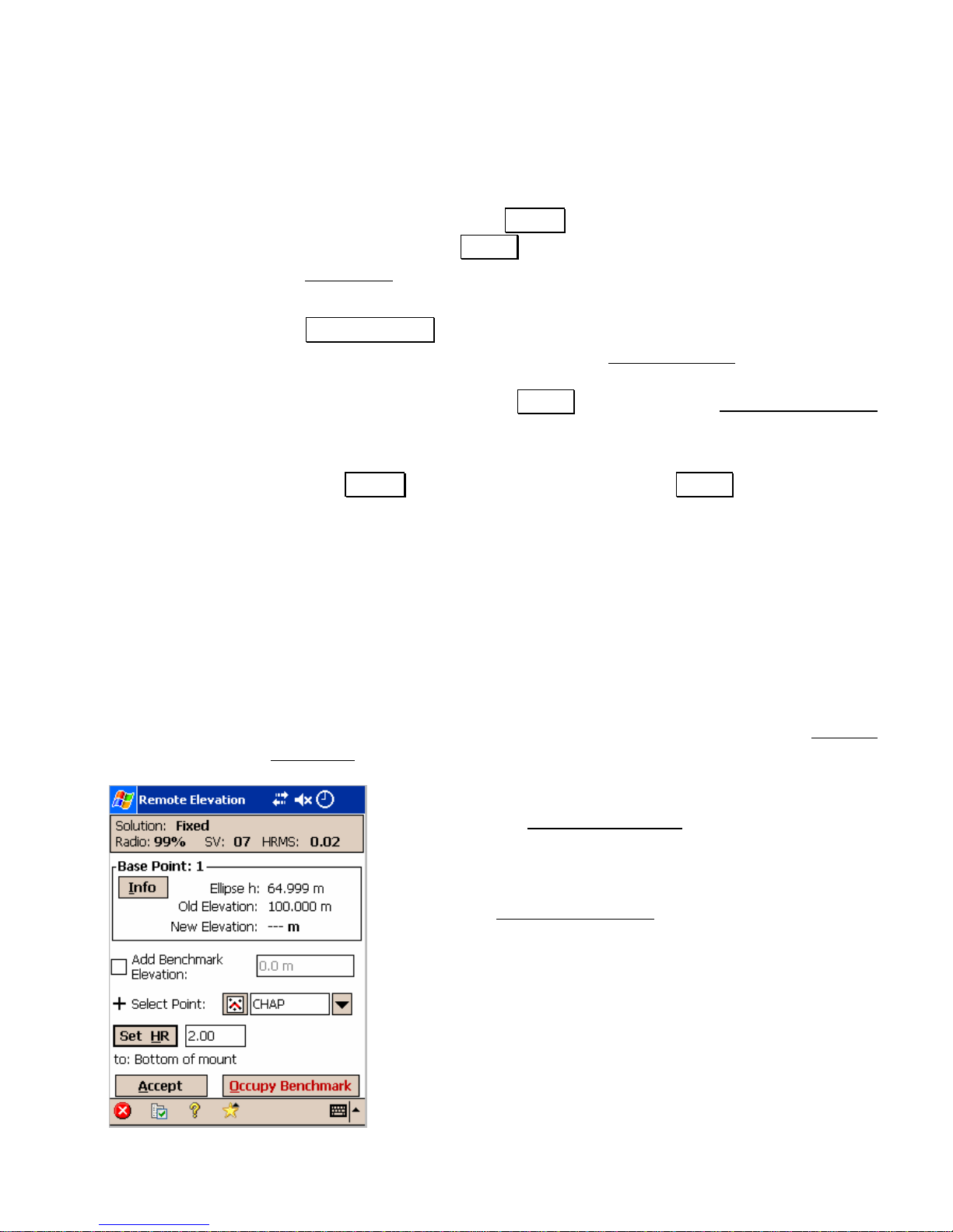
Remote Elevation
If you set your base on a point with known elevation, you can begin
collecting data right away. However, if your base station is on a new
point, then you should calculate the elevation of the base and create
or update a vertical site before collecting new data. This can be done
in conjunction with horizontal localization, or you can use the Remote
Elevation screen.
You can use the Remote Elevation
screen to occupy a
vertical benchmark with the rover. Applying the results
of the occupation will update the base point elevation
and create a new one-point vertical localiza t i on without
entering the Solve Localization
wizard. This procedure
will not effect the horizontal localization adjustment.
Page 40

Survey Pro GPS User’s Manual
40
The following conditions must be met in order to use the Remote
Elevation routine.
• The base and rover must be set.
• The vertical projection mode must be set to Localization
(+Geoid) and a geoid model must be attached to the current
coordinate system.
• The horizontal coordinate system must be solved.
1. Open the Survey
| Remote Elevation screen.
2. If your benchmark is not in the job file, select the Add Benchmark
checkbox, enter the Elevation, and specify a new point number in
the New Point field.
Note: You cannot enter a new elevation for an existing point using the
Remote Elevation routine.
3. If your benchmark is a point in the job file, enter the point name.
4. Occupy the benchmark with the rover and tap
Occupy Benchmark to access the Occupy Control Point
screen and
begin measurements to the point.
5. When you are satis fied w ith the measurement, tap Accept. You
will return to the Remote Elevation screen and the base station’s
newly calculated elevation is display ed. The occupied benchmark
point has now been added to the job file as a GPS control point.
6. If the new base elevation is acceptable, tap Accept from the
Remote Elevation screen to open the A d j ust with Projection
wizard, which will show a preview of the points to be adjusted,
including the update to the base position elevation. Tap Apply to
update the vertical coordinate system in the job file, and apply
the adjustment to the job file points.
Page 41
RTK Data Collection
41
Localization Default Zone
When your horizontal projection mode is Ground – TDS Localization,
there is usually no need for you to setup the map projection zone
used. Survey Pro will initialize a default m ap projection, scaled for
ground distances, when you set the first RTK base in the survey.
You can reset this default zone in two ways. First, You can key in
parameters by hand, or you can select a Ground – TDS Localization
coordinate system from the databas e. The Localization Set Zone
screen can be used to modify the default map proj ection zone used.
You may wish to do this when your base is more than 100 m higher or
lower than the survey area in order to have the correct ground scale
factor used. The Select Coordinate System
screen can be used to
select a zone or site record from the TDS Localization ZoneGroup
collection in the coordinate system database.
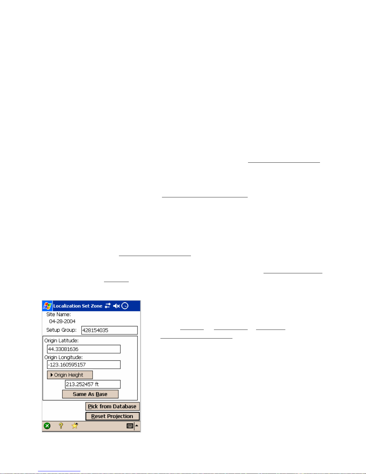
Localization Set Zone
The Localization Set Zone screen is used to manually key in the
parameters for the default map projection zone used in the
localization adjustment. You can also open the Select Coordinate
System screen where you can choose a record from the coordinate
system database file.
1. Go to Survey
| Projection | Set Zone to open the
Localization Set Zone
screen.
2. Enter the Setup Gro up for the zone. The setup group
is used to associate this zone with the autonomous
base setup. The setup group should usually be the
same as the current RTK base.
3. Enter the Ori gin Latitude and Origin Longitude for the
zone. The origin coordinate is usually at the same
location as the RTK base.
Page 42

Survey Pro GPS User’s Manual
42
4. Enter the Origin Height for the zone. The origin height is used to
calculate the zone’s scale factor to configure this zone for ground
distances. Alternatively, you can toggle this control and enter the
Origin Scale directly.
Note: If you have an RTK base configured in Survey Pro, and if you
wish to set up this localization zone to match the setup group and
location of that base, tap Same As Base to fill in all the parameters on
this screen.
Localization Select Zone
You can store and select any coordinate system in the database file
using Save Projection Record on the Projection
screen. Coordinate
systems stored in Ground – TDS Localization mode are put in a special
zone group called TDS Localization ZoneGroup. To selec t Ground –
TDS Localization coordinate systems from the database, open the
Select Coordinate System
screen from the Localization Set Zon e
screen. The procedure for selectin g a coordinate system is the same
as the Mapping Plane mode case, which is described below.
Mapping Plane Select Zone
Use the Select Coordinate System screen to select either
a mapping plane zone or a localized sit e from the
coordinate system database file. This screen is also used
to open the Key In Zone
wizard where you can key in
the parameters of a custom map projection and datum.
1. Open the Select C oordinate System screen. This
may be done automatically by the Start GPS Survey
wizard, or when you tap Select Zone… on the
Horizontal card of the Projectio n screen when in
mapping plane mode.
2. Select the type of database record you wish to choose
in the Data Base box. To pick a map projection zone
from the database, tap Use Database Zone. To pick
Page 43

RTK Data Collection
43
a localized map projection site from the database, tap Use
Database Site.
3. If you are picking a map projection zone, select the Zone Group
from the drop down list.
4. Select the Zone or Site from the drop down list.
5. If you have selected a zone with a datum, the datum name will be
displayed. If you have selected a zone without an attached
datum, such as the database UTM zones, you must select a Datum
from the drop down list.
6. If there is a default geoid attached to the zone or site, Use Geoid
is checked and the geoid model is selected in the drop d own l ist.
You can choose to use this geoid, or you can chang e the geoid
model used by this zone or site.
7. Tap Finish to set the selected zone or site and the selected geoid
(if Use Geoid is checked) as the current coor dinate system.
Note: If you change the geoid model used by a site record, and if that
site record has a vertical adjustment solved, then you will be
prompted that the vertical adjustment parameters will be cleared.
• Use the Delete Zone / Site button to delete zones or sites from the
database. You can only delete user created sites, you cannot
delete the original 'system' records in the database.
• Use the Key In Zone button to open the Key In Zon e
screen
where you can configure a custom map proj ection and datum.
Page 44

Survey Pro GPS User’s Manual
44
Key In Zone
Use the Key In Zone screen to create a custom ma p proj ection and a
custom datum transformation to add to the coordinate system
database file. You can then select this zone as the coordinate system
to use in your job.
1. Pick the Zone Type for the new map projection zon e. Supported
zone types are:
• Transverse Mercator
• Lambert 1 parallel
• Lambert 2 parallel
• Stereographic (oblique and polar)
• Oblique Mercator Angle
2. Pick the Datum Type f or the ne w m ap projection zone. Choices for
datum are:
• Pick from Data Base. Select this choice to use a datum
from the coordinate system database.
• Custom Molodensky. Select this choice to enter a custom
three-parameter datum transformation.
• Custom Similarity. Select this choice to enter a custom
seven-parameter datum transformation.
3. Select the Azimuth type for the new map projection zone. Choices
are:
• North Azimuth. Select this choice to have a north azimuth
grid.
• South Azimuth. This choice to have a south azimuth grid.
4. Select the Grid direction for positive coordinat es in the new map
projection zone. Choices for grid direction ar e:
• North\East Grid. Select this choice to have coordinates
increase positive in the north and east directions.
• South\West Grid. Select this choice to have coordinates
increase positive in the south and west directions.
Page 45

RTK Data Collection
45
Note: The geodetic calculation engine and the Survey Pro coordinate
geometry engine are separate c om p onents. While the geodetic engine
can properly handle southwest grid systems, Survey Pro can only
operate on a northeast grid system. However, since a southwest grid
with a south azimuth is a mirror image of a northeast grid with a
north azimuth, Survey Pro can handle this configuration with the
following work around: You must set the Azimuth Type to North
Azimuth on the Units card of the Job, Settings screen. You then treat
north as south and east as west, and the coordinates will be correct
for a southwest grid and south azimuth zone.
5. Tap Next to enter the zone parameters for the new map
projection.
6. Key in the five or six parameters for your new map projection
zone.
7. If your zone is Oblique Mercator Angle, the next screen is used to
pick the Origin and Azimuth values.
8. Tap Next to select the datum. The screen that opens will depend
on the datum type you specified on t he first screen.
9. If you selected Pick from Data Base, pick the database Datum from
the list. If you selected either Custom Molodensky or Custom
Similarity, then select an ellipse for the new datum. You can select
Ellipse from Data Base to use an ellipsoid record from the
database, or you can select Key In Ellipse to input parameters for
a custom ellipse.
10. Tap Next to open the next screen. If you are using a database
datum, the next screen displays the parameters for the new map
projection zone and you can Store the record.
11. If you are using a custom datum, enter the datum translations
from WGS84 to Local.
Note: Note the sign of the datum shift and rotation parameters.
Survey Pro requires you enter the datum transformation parameters
in the direction of WGS84 to Local. If your datum parameters are
given as local datum to WGS84, you will need to invert the conversion
parameters before entering into Survey Pro.
Page 46

Survey Pro GPS User’s Manual
46
12. Tap Next. If you are using a Custom Molodensky datum, the next
screen will be the final screen where you can Store the record.
13. If you are using a Custom Similarity datum, enter the rotation
from WGS84 to the local datum. Also enter the scale, in parts per
million from WGS84 to the local datum.
14. Tap Next to open the final screen where y ou can review the
parameters for the new map projection zone and where you can
Store the record to save it in the coordinate system database file.
Mapping Ground Coordinates
Ground Coordinates in mapping plane mode is a mechanism to use
ground level scaled coordinates when the und erlying coordinate
system is a conformal mapping plane zone selected from the
database. This function is useful if you must work with a specified
map projection zone, but you wish to work with distances in a ground
scale.
You can switch to Ground Coordinates using any Mapping Plane mode
zone or localized site. You can not use Ground Coordinates when the
horizontal projection mode is Ground – TDS Localization. In this case,
the default map projection is already configured to produce ground
scale coordinates.
The following section describes how to setup Ground Coordinates.
This section explains the Ground Coordinate parameters, how to
switch between grid and ground coordinates in the job file, and how to
set the conventional survey scale factor to properly reduce EDM
distances when in either mode.
Page 47

RTK Data Collection
47
Switching from Grid To Ground
1. Any time a Mappin g Plane mode zone or localized site record is
selected, go to the Survey
| Projection screen and tap
Setup Ground Coordinates….
2. In the Projection Definition box, select Use Ground
Coordinates.
3. Select the Ground Coordinate Origin; this is the point
around which the scale factor will be applie d. The
recommended procedure is to select or key in a
project location close to the survey are a. It is most
important that the origin be close to the he ight of
the survey area for proper ground scale. You can
also choose to apply the ground scale factor at the
map projection origin with any height scale factor
you wish.
4. Tap Next>. If you are using a keyed in origin point,
enter the coordinate of the origin and tap Next>.
5. The next pag e wi ll display the local geodetic
coordinate of the origin Reference Point and the
Ground Scale factor calculated for that point. The
scale factor is the inverse of the combined scale
factor for the selected map projection zone at the
origin reference height, and it is automatically
calculated based on your reference position. If you
wish to use a different scale factor, tap Override scale
calculated from location and enter your value in the
Ground Scale Box. Tap Next>.
Page 48

Survey Pro GPS User’s Manual
48
6. Review the Ground Coordinate parameters:
Reference Point Location, Ground Offsets, and
Ground Scale. When you are satisfied with the
setup, tap Finish.
7. If your projection record is a map projection zone,
the ground coordinate parameters will be added to
the zone record to create a zone based site. If you
are already using a site record, the parameters will
simply be applied. In both cases, the Adjust with
Projection wizard will open with the Results screen
to show the updated job file points. Tap Apply to
update the coordinate system and job file points.
Note: If your projection is a zone based site, then the
localization parameters will automatically be converted into the
corresponding ground coordinate values. You do not have to resolve
the localization.
8. If the conventional Survey Scale factor is not set to
1.0, you will be prompted to set it to 1.0. Using
Ground Coordinates, EDM distances correspond 1:1
to grid distances.
Switching from Ground To Grid
1. When Ground Coordinates are set, go to the Survey
| Projection
screen and tap Setup Ground
Coordinates
2. In the Projection Definition box, select Use Grid
Coordinates.
3. Tap Accept to switch back to the mapping plane
grid coordinate system, and open the Adjust with
Projection wizard at the Results screen. Tap Apply
to set the coordinate system and update the job file points.
Page 49

RTK Data Collection
49
Note: If your projection is a zone based site, then the localization
parameters will automatically be converted back to the map
projection values. You do not have to resolv e the localization.
4. Switching back to mapping plane grid coordinates, the
conventional Survey Scale Factor is usually set to 1.0. You will
be prompted to update the scale to the correct value to reduc e
EDM measured distances to the mapping plane.
Vertical Projection
The vertical projection is usually setup in conjunction with the
horizontal setup. However, you can change the vertical projection
independently after setup of the horizontal Grou nd - TDS Localization
or Mapping Plane zone.
Select Geoid Model
Use the Select Geoid Model screen to select a geoid model and data
file to use with either the Grou nd - TDS Localization or Mapping Plane
zone. This screen is also used to remove the geoid from the current
projection record.
1. Select a Geoid Model to use from the list.
2. If there ar e no data files for the selected geoid
model, the File control will display "No .ggf files for
this geoid." If there is only one data file for the
selected geoid, the File control will display that .G GF
file name. If there are multiple dat a files for the
selected geoid, select the geoid you wish to use from
the list. When there is a geoid file disp layed, the
File Name control displays the data file name from
the .GGF file header.
• Tap Accept to set the geoid for the current
projection record and/or change the da ta file used by
the current geoid model.
Page 50

Survey Pro GPS User’s Manual
50
• Use the Remove Geoid From Zone button to remove the geoid
model from the current projection record.
Using Ellipsoid Heights
Ellipsoid Height mode is a method that stores the local ellipsoid h ei ght
measurement as the vertical coordinate. Use elli psoid heights if the
vertical is not important to the project, or when you intend to
transform heights to elevations in the office using a separate
program.
1. Set the Vertical Projection Mode on the Job
, Settings, Projection
card to Ellipsoid Height.
Tap OK. Using vertical ellipsoid heights requires no additi onal
projection solution.
RTK Data Collection
Once your horizontal and vertical projections are solved, you are
ready to collect data. The different measure mode settings and data
collection options are described below.
Measure Mode
1. From the Data Collection screen or from any GPS stake out
screen, tap Settings to open the Job
| Settings | Measure Mode
card.
2. Select the receiver dynamics.
¾ Static on occupy will set the receiver to ‘static’ mode for
point occupations. When in static mode, the receiver
assumes no antenna movement and uses advanced
averaging techniques to compute the most precise position
possible.
¾ Dynamic always will leave the receiver in ‘dynamic’ mode
for point occupations.
3. Select how to Store GPS Raw Data.
Page 51

RTK Data Collection
51
¾ Lat, Lng, Ht will store an EP record in the .RAW file for
each point accepted.
¾ EP + Bl,CV will store an EP record, plus the raw base line
(dX,dY, dZ) and variance covariance information in the
.RAW file.
¾ EP + Bl,CV + Rx Raw will store an EP record, plus the raw
base line and variance covariance information in the
.RAW file, and send the station information to the
receiver’s internal file for post processing.
¾ EP + Rx Raw will store an EP record in the .RAW file and
send the station information to the receiver’s internal file
for post processing.
Note: Ashtech users store an Ashtech format .OBN record in a
separate file and do not store BL,CV records in the .RAW file.
Note: Raw data types + Rx Raw (and/or + OBN for Ashtech users) are
only available when Receiver Dynamics is set to Static on occupy.
Note: All receivers need to be in static mode to record Rx. Raw, and
some receivers always record Rx Raw when in static mode. If the
combination of settings you select is not compatible for your receiver,
you will be prompted to change the settings..
4. Select the Accept filt er.
¾ Fixed RTK only will reject all positions that are not fixed.
Code, Float, or Fix will allow you to accept any position
accept autonomous or invalid data.
Note: If you are collecting simultaneous RTK and post processing
data, you can accept an autonomous position based on the
Job/Settings, Post Process card. If enabled, you will either be
prompted to put the autonomous position on a separate layer, or it
will automatically be stored on a separate layer.
Page 52

Survey Pro GPS User’s Manual
52
5. Set the Acceptance Criteria.
¾ Acceptance Criteria is used to check each solution you
accept. If the measurement exceeds the criteria, you will
be prompted to accept or reject the point. Check this box
if you want to enable criteria checking. Enter a maximum
value for HRMS, VRMS, and/or PDOP in the fields. Only
fields with a non-zero value will be used for criteria
checking.
¾ To accept data points automatically using the selected
criteria, check the Auto Accept box at the bottom of this
page.
6. Tap OK to return to the Data Collection
screen.
Data Collection
The GPS Data Collection screen is used to add points to
the job file. There are several methods to collect data.
Occupy Point
Use this method if you want to occupy a point with the
rover for any amount of time. When you start a point
occupation, the receiver will be put in static mode for the
most precise measurement possible, and the e vent will
be recorded in the post processing log file (depending on
your settings).
1. Go to the Survey
| Data Collection screen.
2. Enter a poin t nam e in the Point field.
Note: If you have Store GPS Raw Data set to + Rx Raw
(or + OBN for Ashtech users), your point name must be a valid Site Id
for the receiver model. If your point name is not v alid, you will be
prompted to change it.
3. Enter a Description.
Page 53

RTK Data Collection
53
4. If your antenna height h as changed, enter a new value in the
Rover field to update the value in Survey Pro and in the receiver.
If your antenna type and measure to method have changed since
Rover setup, then tap Setup HR to change and update it.
5. Tap Point to begin measurement. If the Point name is a new point
for the job file, the Occupy Data Points screen will open. If the
Point name already exists, you will be given up to three choices:
overwrite, use next available nam e, or occupy the point as a check
point. If you choose overwrite or use next available, then the
Occupy Data Points
screen will open. If you choose to occupy the
point as a check point, the Check Control Point
screen will open.
6. In each case, the receiver will be put into static mode and the post
processing event will be logged to the data file ( when the
Measure Mode
settings are Static on occupy and + Rx Raw) and a
site occupation begins.
7. The Occupy Data Point screen (or Check Control Point screen) is
updated with the local coordinate calculated from the
measurement. When you are satisfied with the m easurement tap
Accept to return to the Data Collection
screen
8. Check the Results tab for details on the last measurement.
Check the Map
tab to see the points plotted as they are stored.
Store SS
Use this method if you want to store a point at the current rov e r
position. When you tap Store SS, Survey Pro will check the current
position against the measurement criteria. If the position is good,
then Survey Pro will store the point. You m ay be prompted for
description, layer, and/or attributes depending on your settings.
Offset Point
Use this method if you cannot occupy a point directly, but you can
occupy a location close by and provide an azim uth and distance to the
point.
1. Go to the Survey
| Data Collection screen.
2. Tap Offset to open the Offset Shots
screen.
Page 54

Survey Pro GPS User’s Manual
54
Note: You can enter the offset data before or after you occupy the
reference point with GPS.
3. Tap Occupy GPS to occupy the GPS reference point. You will be
prompted for a point name to store the reference point. The
receiver dynamics are set and a site occupation begins. When you
are happy with the measurement, tap Accept to return to the
Offset Shots screen.
4. Enter the distance from the GPS reference point to the offset
point. You can enter the distance by hand or you can get it from
the selected conventional instrument by tapping Shoot Laser.
Note: You have to switch to conventional mode to configure the laser
range finder or total station.
5. Enter the direction (azimuth/bearing) from the reference point to
the offset point. You can enter a direc tion in one of the following
ways:
¾ Using the horizontal angle returned from the
conventional instrument if you took a shot.
¾ Occupying a point on line with the reference point and
the offset point. After you occupy the reference point,
tap Direction from Two Points and then occupy a point
on line with the reference point and the offset point.
When you are done occupying the on line point, you
will be prompted for the direction to your offset point.
¾ Entering a value by hand, such as when you measure
the offset direction with a compass.
6. Tap Store to store the offset point.
7. Store any nu mber of additional offset points from this GPS
reference point. The shot data for each point is rec o rded in .RAW
data. Tap Close when you are done storing points.
Page 55

RTK Data Collection
55
Feature Collection
Use this method if you want to continuously collect multiple points
using either a measurement interval or by m anually accepting each
point. You can select from six different data collection modes.
1. Go to the Survey
| Data Collection screen.
2. Enter a poin t nam e in the Point field. If this point already exists,
you will be prompted to overwrite or choose the next available
point.
Note: If you have Store GPS Raw Data set to + Bl,CV or + Bl,CV + Rx
Raw, feature collection will not store base line records because there
is no discrete site occupation of each point. T h erefore, the point name
does not need to be a valid Site Id.
3. Enter a Description.
Note: For continuous data collection (except Manual: multi
descriptions), once the first point is accepted, all additional points will
be stored with the same description, layer, and attr ibutes. When
using Manual: multi descriptions mode, you will be prompted for
description, layer, and attributes (if set) after every point.
4. Tap Feature. On the Feature Collection screen, select a Method.
An explanation of the selected method is displayed at the bottom
of the screen. See the Reference Manual for m ore information.
5. If you select a continuous method, or the Hold Still method, you
must specify an appropriate Interval.
6. Tap Start to begin measurements. The Occupy Data Points
screen displays the local coordinat e.
7. When you are ready to begin continuous collection, tap Store SS.
8. If you are using a cont inuous interval, Accept disappears and
points are stored when the interval is exceeded.
Page 56

Survey Pro GPS User’s Manual
56
9. If your mode is Manual, tap Accept when you want to collect a
point. If your mode is Manual: multi descriptions, you will be
prompted for a description, layer, and attributes (if set) for each
point.
10. If you want to see a list of points stored so far, tap View Points.
11. If you wish to store points at any time during your continuous
interval, tap Store SS.
12. Tap Done to end feature collection and return to the Data
Collection screen.
Note: When doing continuous data collection, if your interval is
exceeded, but your acceptance criteria or RMS criteria are not met,
then you will be prompted to Accept the point an yway or to Wait for
the measurement to pass. If you choose to Wait, and then Cancel, you
will be prompted to Accept the point anyway or to Exit.
Occupy Control Point
Use this button to open the Control Points screen (Page 27), where
you can occupy a control point for the localization adjustment, or
occupy a check point to verify the current coordinate system solution.
Post Process
Use this button to open the RTK Rover Session screen. This screen is
used to start and stop point occupations in the post processing log file.
Use the RTK Rover Session
screen when you wish to perform
additional occupations on the same point name, without effecting the
point’s coordinates in Survey Pro.
Page 57

RTK Data Collection
57
RTK Stake Out
Stake out with GPS is very similar to stake out with conventional
instruments. See the User’s Manual for details on the different
staking procedures. Below is a description of the two special features
of stakeout with GPS.
o >Roving / >Occupying
1. When you first start any GPS staking screen, measurements are
started in the GPS receiver in dynamic (moving) mode. This is
necessary as you navigate to the design point, and is indicated on
the screen with the toggle button in the >Roving position.
2. When you arrive at the design point, if you want to take a more
precise measurement, you need to switch to >Occupying mode.
This will switch the receiver from motion t o static (depending on
your Receiver Dynamics setting).
Note: When Store GPS Raw Data on the Job | Settings | Measure
Mode screen is set to + Rx. Raw (and / or +OBN for Ashtech)
switching from ROVING to OCCUPYING will start a session in the
receiver, so you will be prompted for a point name and description.
The receiver session will be completed and the measurement stored
when you tap Done. The occupation is not stored in the Survey P r o
.RAW file if you toggle back to ROVING.
o 5 Hz Mode
1. When you first open any GPS staking screen, the default is to
start measurements in Five Hz mode. This will configure the
receiver to calculate positions five times a second and the display
will update in near real time. You can change this setting on the
Job
| Settings | Stakeout card.
2. The recei ver is switched back to One Hz mode when you begin a
site occupation. Also, you can turn off Five Hz mode by tapping
the 5Hz check box on any stake out dialog.
Page 58

Survey Pro GPS User’s Manual
58
Note: Five Hz mode is for quick navigation to the point, it does not
provide the most precise solution of coordinates. When you switch
from roving to occupying, the receiver is automatically switched to
one Hz. When you switch back to Roving mode, the receiver will
toggle back to 5 Hz mode (depending on your settings).
Page 59

59
Post Processing
Post processing data collection involves logging GPS raw data to a
file, and then combining the data from m ultiple receivers. Software
on the PC is used to process the base line measurem ents. This
section describes how to collect GPS raw data for post processing with
Survey Pro. In this section, you will learn:
¾ How to start a static post processing session.
¾ How to start a stop and go post processing session.
¾ How to set the station information and antenna height for
both static and stop and go point occupations.
¾ A general description of the data proc essing to compute
precise measurements from the data files.
Field Procedure
Turn On Data Recording
1. Go to the Job | Settings screen.
2. On the Post Process
card, specify a non-zero recording
interval.
Note: For simultaneous RTK and post processing data collection,
this is all you need to do. Receiver recording will be started
automatically when you configure the RTK base and rover. Data
collection sessions will be completed automatically when you occupy
an RTK point. If you wish to do post processing only data collection,
you need to complete the next step before tapping OK.
3. Create a post processing receiver profile (Page 8).
Page 60

Survey Pro GPS User’s Manual
60
Start Recording in Receiver
1. Go to the Survey | Post Processing screen. You will be prompted
to choose a receiver from the available post processing receivers
and the Post Processing
screen will open.
Note: If you are currently connected to the RTK base or rover
receiver, you will not be allowed to enter the P ost P rocessing screen.
If you tap Post Processing when connected to the RTK base or rover,
Survey Pro will check the receiver to see if it is currently logging
data. If it is, you will be prompted if you wish to stop data logging on
this receiver. If the receiver is not logging data, you will be prompted
if you wish to clear the RTK setup so you can set this receiver as a
post processing only receiver.
2. Choose Start Static if you want to configure a receiver to record
raw data at a stationary setup. Choose Start Stop/Go if you want
to configure a receiver to do stop and go data collection.
3. Tap Change Settings to select a new Recording Interval or
Threshold values.
4. Tap Setup HR to select an antenna type and enter the slant or
vertical measurement.
5. Tap Start Recording to create a new file in the receiver memory or
on the data collector and begin logging GPS raw data.
Note: Start Recording only begins the logging of raw data to the
receiver’s internal memory. It does not send the station or antenna
information. For a static receiver, the Receiver Session screen is
opened and you then enter the station site ID and send th e antenna
information to the static receiver. For a stop and go receiver, the
Receiver Session screen is opened where you can mark the start and
stop of sessions as you occupy points.
Page 61

Post Processing Data Collection
61
Data Collection
1. After recording is started, you can use the Receiver Session
screen to mark the start and stop of point occupation sessions.
This screen is automatically open ed after you first start logging.
You can also open the Receiver Session
screen by going to Data
Collection on the Survey menu and s electing a post processing
receiver type.
2. Choose if you wish to Store point in: Receiver and job file or the
Receiver file only. If you choose to store the point in Receiver and
job file, then the site ID must be a unique point name in the
Survey Pro job and you will be prompted to put the point on the
autonomous layer. If you choose to store the point in the Receiver
file only, the site ID can be any valid name for the receiver and
you are not prompted for layer or attri butes.
Note: If you are using this screen with the current RTK rover, you
can store points only on the receiver’s file. To store points in the
receiver and in Survey Pro, use a regular RTK data collect ion routin e
and set the raw data setting to include + Rx.
3. Enter a Site ID and Description for this point.
Note: If the Site ID or Description is not valid for your model of
receiver, you will be prompted to modify them.
4. Enter a Duration for this session. If you enter 0 or if you check
Log Until Stop, the session will continue until you tap Stop.
Note: In order for a timed session to stop properly, you cannot tap
Close out of this screen until the timed session is finished. If you
wish to exit this screen while the session is underway, you should use
Log Until Stop.
Page 62

Survey Pro GPS User’s Manual
62
5. Tap Start to mark the beginning of this site occupation in the
receiver raw data. If you are storing the point in Survey Pro, you
will be prompted for the autonomous layer and attribut es (if set)
at this point.
6. If you specified a Duration, you can watch the tim e Remain /
Elapse count down or up depending on your receiver. If you
choose to record until stop, the Remain / Elapse field shows ”…”.
When the session is done, Survey Pro will send an end of
occupation event marker to the receiv er.
7. You can end a session by tapping Stop.
Office Procedure
1. Use the software supplied by the receiver manufacturer to
download the files from receiver or the data c ol lector onto your
PC.
2. Use your GPS baseline processing software to combine the raw
data from different receivers and gene rate GP S base lines.
Note: See the documentation supplied with your PC software for
details on downloading and processing GPS raw data from the
receiver’s internal memory.
Page 63

63
Projection Utilities
Survey Pro has a number of tools to help you work with map
projections and coordinate system. This section des cribes the Adjust
with Projection wizard and the Proj ection Calculator tools. In this
section you will learn:
¾ How to use the Adjust with Projection wizard to update the
job file points when the coordinate system changes.
¾ How to use the Adjust with Projection wizard to adjust
selected points from one coordinate system to another.
¾ How to use the Projection Calcu lator
to calculate convergence
and/or scale factors for a selected mapping plane zone.
Adjust with Projection
The Adjust with Projection wizard is used to adjust job file points
from one coordinate system into another. Any time you change the
job file coordinate system, the Adjust with Projection
wizard will run
the job file points through the adjustment and show you a preview of
the results. When you accept the results, the coordinate system is
updated, and the point coordinates are updated in the job file.
The Adjust with Projection
wizard can be opened in three different
ways: Updating the localization adjustment or ground site
parameters; Changing the coordinate system zone or site; Manually
selecting points using the Adjust with Projection
wizard opened from
the Survey
menu when in GPS mode.
• When you update the localization adjustment or ground site,
Survey Pro will automatically calcula te the adjustment to all of
the effected job file points and open th e Adj u st with Projection
Results screen. When you tap Apply to accept the change, Survey
Pro will update the job coordinat e system and apply the
adjustment to the points. This behavior is the result of the
following functions in Survey Pr o: Solve Localization wizard,
Remote Elevation
, Setup Ground Coordinates wizard.
• When you change the coordinate system, Survey P ro will open the
Adjust with Projection
Prompt Adjust screen. This screen
Page 64

Survey Pro GPS User’s Manual
64
displays details about the nature of the coordinate system
changes between the old and new system. You can choose to
proceed with the adjustment, or to not adjust points. If you
choose not to adjust points, the coordinate system is updated, but
no point coordinates are changed. If you choose to proceed with
the adjustment, Survey Pro will show the Preview screen, and
update both the coordinate system and the points in the job file
when you tap Apply. This behavior is the result of the following
functions in Survey Pro: Select Coordinate System , changing
horizontal projection mode on the Job
| Settings | Projection
screen.
• When you go to the Survey
| Adjust with Projection screen,
Survey Pro will open the Adjust with Projection
Select Points
screen There are two different methods to adj ust points.
Depending on your choice, you will select the source and
destination coordinate systems, the adjustment will be calculated,
and Survey Pro will show the Results screen. When you tap
Apply, the point coordinates will be updated, but this routine will
not change the coordinate system settings.
Adjust with Projection – Select Points
The Adjust with Projection Select Points screen is used to select job
file points for adjustment, and to choose which type of projection
adjustment to apply. The Select Points screen is the first step of the
wizard when opened from the Survey
menu. There are
two different adjustment modes, each with two o ptions
to adjust points:
Source to Destination Projection: Use this mode when
you wish to update the plane coordinates of points by
choosing two coordinate systems from the database.
The source coordinate system defines t h e current
locations and the destination coordin ate system defines
the resulting locations. There are two options in this
mode:
• Adjust all selected points: use this option to
adjust all selected points. Points with geodetic
Page 65

Projection Utilities
65
coordinates will be transformed into the destination
coordinate system using their WGS84 values. P oints with
plane only coordinates will be transformed into temporary
WGS84 coordinates using the source coordinate system, then
transformed into new plane locations using the destinatio n
coordinate system.
• Adjust only geodetic points: use this option to adjust onl y
selected points with geodetic coordinates. Points with
geodetic coordinates will be transformed into the destination
coordinate system using their WGS84 values.
Readjust with Current Projection: Use this mode when you wish to
update locations using the current coordinate syste m . There are two
options in this mode:
• Geodetic to Plane: use this option when you want to upda te
the plane location of all points with g eodetic coordinates. The
WGS84 value of any selected point wit h geodetic coordinates
will be transformed into a new plane value using the current
coordinate system.
• Plane to Geodetic: use this option when you want to update
the geodetic locations of all selected points. The plane value
of all selected points will be transformed into a n e w WGS84
value. Any points that already have ge odetic coordinates will
be updated. Any points that were plane only w ill become
geodetic points.
1. Select points for adjustm e nt.
2. Choose the adjustment mode and options.
3. Tap Next
Page 66

Survey Pro GPS User’s Manual
66
Adjust with Projection – Select
Coordinate System
The Adjust with Projection Selec t Coordinate System screen is used
to select the source and destination coordinate system when your
adjustment mode is Source to Destination Projection, or to view details
of the current projection when your adjustment mode is Readjust with
Current Projection. This screen is only used when the wizard was
opened from the Survey
menu. This screen is similar to the Select
Coordinate System screen (Page 42), with the following additional
controls:
Source / Destination Projection Record: is where you select what
kind of record to select from the database. Along with the zone and
site choices, you can also choose to use the Current Projection.
Details: opens the Projection Details
screen where you can view the
parameters of the coordinate system.
1. Select the type of record t o use.
2. Select the re cord from the database, or use the current job file
record.
3. Tap Next>.
Adjust with Projection – Prompt
Adjust
The Adjust with Projection Prompt Adjust screen is only shown when
the wizard opens automatically when you change the coordinate
system. This will be the case when you select a zone or site using the
Select Coordinate System
screen, when you change or remove the
geoid using the Select Geoid Model
screen, or when you change the
horizontal projection mode on the Job
| Settings | Projection screen.
The Prompt Adjust screen describes the difference between the two
coordinate systems, and gives you the option to adjust or to not adjust
the job.
Page 67

Projection Utilities
67
1. Choose to Adjust job with new projection or Do not adjust job.
• If you pick Do not adjust job, then the Next>
button is hidden and the Done button shows.
Tap Done to update the coordinate system but
not change any job file points.
• If you choose to Adjust job with new
projection, you may have the choice to
Adjust all points or to Adjust only points
with geodetic coordinates. These two
cases are described in the Select Points
section. The criteria used to determine
if this choice is allowed is based on the
nature of the change between the
current and the new coordinate system.
This may be different for the horizontal
and vertical dimension. The title of the
box will indicate the dimension consi dered for this
setting.
2. Tap Next> to open the Preview screen.
Adjust with Projection – Results
The Adjust with Projection Results screen is used to
preview the results of the adjustment before an ything is
applied to the job file. The default view is to list the
action and results only for points that will be updated in
the adjustment. You can tap Show all points to update
the list to show the reason unchanged points are n ot
adjusted.
1. Review th e results.
2. Tap Apply to update the job.
Page 68

Survey Pro GPS User’s Manual
68
Projection Calculator
You can use the Projection Calculator to calculate combined scale
factor for scaling conventional distance measurements to the
mapping plane. You can also use the P r ojection Calculator
to
calculate meridian convergence for reducing geod etic azimuths (such
as a sun shot) to grid bearings.
Scale Factor Calculator
1. Go to the Survey | Projection Calculator screen.
2. Choose a point on the mapping plane for scale computation in the
Select Point control. Tap Solve Scale>.
3. Enter a height to comput e Ellipsoid Scale Factor. This calculation
uses the height of the point above the el lipsoid to correct for the
effect of the terrain above the re ference surface.
4. Tap Solve> to calculate the combined scale factor with the
selected values. The combined scale factor is displayed in the
Ground to Grid box. The inverse combined factor is displayed in
the Grid to Ground box.
5. Tap Accept when you are done. Both numbers are saved in the
Past Results list so you can use them in other calculations.
Convergence Calculator
2. Go to the Survey | Projection Calculator screen.
3. Choose a point on the mapping plane for convergenc e
computation in the Select Point control. Tap Solve Rotation>.
4. The convergence and rotation are calculated. The conver gence is
displayed in the Geodetic N to Grid N box. The rotation is
displayed in the Grid N to Geodetic N box.
5. Tap Accept when you are done. Both numbers are saved in the
Past Results list so you can use them in other calculations.
Page 69

69
Managing GPS
Coordinates with TDS
Survey Pro for Windows CE uses a binary file with the extension
*.job. A .JOB file point record will contain a point nam e, plan e
location (N, E, Z), and a description. It may also contain geodetic
coordinates for points calculated, imp o rted, or measured with GPS, as
well as poly lines, alignments, layers, attributes, base maps, and
automatic line work structures.
This section describes different ways to manipulate geodetic
coordinates with both Survey Pro and ForesightDXM. In this section,
you will learn:
¾ How to use the Survey Pro Edit Points
screen to edit plane
and geodetic locations, and geodetic flags.
¾ How to use the Survey Pro Import menu to import
coordinates and coordinate systems, and how to merge GPS
coordinates from a *.GPS file.
¾ How to use ForesightDXM (DXM) and Trimble Geomatics
Office (TGO) to manage job files with geodetic coordinates
from GPS measurements and coordinate system d efini tions.
Survey Pro
Edit Points
You can edit all of a point’s values using the Edit Points screen from
the Job
menu. This is described in more detail in the User’s and
Reference Manual. Below are some special instructions for editing
geodetic coordinates.
1. Select the point you want to edit and tap Edit, or double tap the
point in the list to open the edit screens.
Page 70

Survey Pro GPS User’s Manual
70
2. The three ca rds of the Edit Point
screen display the current
properties and the plane and geodetic locations of the selected
point.
3. On the Geodetic card, you can tap Advanced to open the Edit GPS
Point Flags screen. This screen allows you to edit the flags
associated with GPS points:
• Set up group: This flag identifies groups of points collected
from the same autonomous base setup. For more information
on set up groups, see Page 32.
• GPS Control Point H/V: These flags identify points to be
included in the localization control point list and whether to
use those points for the horizontal and/or vertical solution.
For more information on set up groups, see Page 32.
4. If you change either the plane or geodetic location, and the point
has geodetic coordinates, will be warned of the possible
consequences, and, depending on your projection settings,
prompted to rectify the plane and geo detic coordinate before
accepting.
Import
You can use File | Import or File | Import Control to add point, line,
and coordinate system values from a number of input file types. This
section describes importing geodetic coordinates and coordinate
systems into the job file.
Import Job (Control)
You can use the Import or Import Control screens and set the Type to
Job Files to add points to your job from another job file. Points from
the imported job will be copied into your current job file. The
imported job file can also be used to set the coordinate system of the
current job file:
• If the imported job has a coordinate sy stem set and your current
job does not, you will be prompted if you want to set the
coordinate system from the imported job file.
Page 71

Managing GPS Coordinates
71
• If the imported job and the current job have different coordinate
systems set, then you will be prompted that they ar e different;
you can cancel the import or import the points but keep the
current job projection.
Import ASCII File
You can use the Import screen and set the Type to Text Files to add
points to your job from an ASCII text file. The ASCII Import Wizard
allows you to import Plane, Geod etic (DMS), and Geodetic (decimal)
coordinates. When you import Geodetic (DMS) and Geodetic
(decimal) coordinates Survey Pro will use the following rules to set
the plane location:
• If you have a valid coordinate system solved Survey Pro will
calculate the plane location for each geodetic point imported.
Survey Pro will set the northing, easting, and elevation for any
points that could be transformed without error.
• If you do not yet have a valid coordin ate system solved, Survey
Pro will set the plane location to (0.0, 0.0, 0.0). You would then
have to use the Adjust with Projection wizard in some manner to
rectify the geodetic to plane coordinates.
Import .GPS File
You can use the Import screen and set the Type to GPS File to merge
geodetic coordinates from a .GP S file generated using Survey Pro
DOS.
1. Open the job with the project’s plane coordinates. You can open
the *.CR5 file directly and it will be converted into a .job file or
you can open a new .job file and import the CR5 coordinates.
2. Go to Job
| Import. For file Type, select, (*.GPS) and pick the
*.GPS file associated with the plane co ordinates.
3. Specify the units of the *.GPS file (for the heights) and tap OK.
4. The GPS coordinates and control point fla gs for each point in the
*.GPS file will be merged with the plane coordinates for the
corresponding points.
5. If you have more than one *.GPS file associated with a set of
coordinates, you can import them one at a time. The coordinates
Page 72

Survey Pro GPS User’s Manual
72
from each .GPS file will be assigned a unique set up group so you
can use them for different localization solutions.
Note: If duplicate points are found, you will be prompted to
overwrite or rename. If you choose to rename, a new point is created
with the original plane coordinate and the new geodetic coordinate.
ForesightDXM and TGO
There are a number of software applications that will work with
Survey Pro .job and .raw files containing geodetic coordinates and
GPS measurement vectors. This section contains a brief descrip tion
of the work flow for downloading fi eld work and uploading
coordinates using either Foresight DXM (DXM) or Trimble Geomatics
Office (TGO) or Trimble Total Control (TTC).
ForesightDXM
Using DXM, you can download Survey Pro job and raw files, open job
files or regenerate job files from RAW data. Yo u can use the DXM
Manage Data function to move data, including coordinate system
definitions, between DXM projects and Survey Pro j obs.
Using DXM, you can create new Survey Pro job files from other job
files or from the project, and upload them to the data collector. Jobs
created from a job or project that has a coordinate system will have
the same coordinate system. Points with geodetic coordinates will
have geodetic coordinates in the uploaded job.
TGO / TTC
Using TGO or TTC, you can download Survey Pro job and raw files to
your hard drive, convert them into Trimble DC files, and import them
into a TGO or TTC project. For both TGO and TTC, the download is
done with a common Trimble component called ‘Data Transfer’. Once
downloaded, the file is automatic ally converted into the Trimble DC
Page 73

Managing GPS Coordinates
73
format and imported into the TGO/TTC project. You can also convert
and import a file already on disk using the Im port function.
TGO / TTC download and import requi res you to choose the .job or
.raw file separately. For most purposes, you will just need to import
the .raw file. When you import the raw file, the converted DC file
contains the coordinate system, the points, and all of the measured
vectors from those points. When you import the .job file, the
converted DC file contains just the coordinate system and the plane
location of the points.
TGO export and upload will create a job file and send it to the data
collector. The job file will contain the coordinate system definition
and plane location of any selected poin ts. The geodetic location of any
GPS measured points is not uploaded to the data collector fr om TGO
or TTC. However, this is not a problem since the coordinate system
definition is uploaded, and this will de fine the transformation from
plane to geodetic.
Page 74

Page 75

75
GPS Coordinates
To represent positions in space you need two things. First, you need
a datum to define an origin, an orientation, and a scale. Second, you
need a coordinate system to specify the locations in the datum. GPS
positions are in a global geocentric datum , using latitude and
longitude angles to specify location. Most engineering and surveying
jobs require positions in a 2D Cartesian coordinate system. In order
to use GPS with most coordinate systems, you must transform the
GPS measurements into local coordinates.
This section offers a more detailed description of some theory and
terminology used to describe geodetic coordinate systems and datums
in Survey Pro. In this section, you will learn:
¾ A description of the WGS84 datum and how to use different
horizontal datum transformations in Survey Pro.
¾ A description of different vertical datums in North America.
¾ A description of geodetic and mapping plane coordinate
systems.
¾ A description of scale corrections for the mapping plane, scale
correction for height, and how to apply the combined scale
factor to convert ground to grid distances.
¾ A description of using Ground Coordinates on a reference
mapping plane.
¾ A description of geoid modeling, and how to use geoid models
for vertical transformations.
Datums
A datum consists of three components: an origin, an orientation, and
a scale. The origin defines the start point, the orientation defines the
direction of the bearings, and the scale defin es the relative magnitude
of the distance units. For example, a surveyor shows up at a new job
site, places a monument in the ground and calls it (5000, 5000, 100).
This establishes the origin of the datum. The surveyor does a sun
shot and calculates the azimuth to a reference object. Astronomic
north at this meridian establishes the orientation of the datum.
Page 76

Survey Pro GPS User’s Manual
76
Finally, the surveyor begins measuring distances with a total station.
The EDM establishes the scale of the d atum.
GPS measurements are taken in a global geocentric datum, the World
Geodetic System of 1984 (WGS84). The WGS84 datum has its origin
at the earth’s center of mass, its orientation defin e d by the earth’s
spin axis and the intersection of the mean meridian of Greenwich
with the mean equatorial plane, and its scale defined by metric
standard measurement.
Geocentric datums such as WGS84 use a rotational ellipsoid to model
the shape of the earth. The WGS84 ellipsoid was based on and is
virtually identical to the Geodetic Reference System of 1980 (GRS80)
ellipsoid. The ellipsoid origin is at the earth’s c enter of mass. Its
minor axis corresponds with the earth’s rotation axis and its major
axis corresponds to the mean equatorial plane.
WGS84 Geodetic v. Local Geodetic
When the coordinate system is a mapping plane in a datum other
than WGS84, positions measured in WGS84 latitude, longitud e and
height, must be transformed into local latitude, longitude, and height
before they can be used to calculate northing and easting with the
specified map projection.
There are three methods of datum transformation supported by
Survey Pro.
• Molodensky Transformation: Is the most commonly used
transformation. Three parameters specify an X,Y,Z shift between
WGS84 and the local datum origin. Survey Pro us es the
Molodensky datum transformation algorithms specified in the
National Imagery and Mapping Agency Technical Report
8350.2.1.
• Similarity Transformation: The most precise method of datum
transformation. The seven-parameter similarity transformation,
also called the Helmert transformation, uses a shif t of XYZ origin,
a rotation about XYZ axes, and a scale to transform from WGS84
and the local datum.
1
http://164.214.2.59/GandG/tr8350_2.html
Page 77

GPS Coordinates
77
• Grid File Datum Transformation: Is used when the datum
differences are not consistent over large areas. A grid file datum
transform uses a data set of shift values. For any location, an
approximate shift can be calculated by interpolating from the
data set.
For many surveying applications, the horizontal and vertical datums
are separate. This is because GPS heights are measured on the
ellipsoid with its origin at the earth's center of mass, while elevation
is a function of local gravity field, which is influenced by the unequal
distribution of mass in the earth.
Below is a description of some common horiz ontal and vertical
datums used by Survey Pro.
Horizontal Datums
• NAD27
The North American Datum of 1927 (NAD27) horizontal datum was
established in the early part of the twentieth century to define a
horizontal coordinate system in North America. The datum
originated at a central point, Meades Ranch in Kansas. From there,
conventional triangulation and trilateration networks radiated
outward to establish new monuments in the system. The datum was
based on the Clarke 1866 ellipsoid, which was the best fitting
ellipsoid for the North American cont inent at the time.
Survey Pro performs a grid transformation for NAD 27 in the United
States using the NADCON datum sets in *.DGF (d atum grid file)
format. Several specific Molodensky datum transf orm ations are also
available for other areas in North America.
Note: To use a grid datum, you must have the pair of *.dgf files for
latitude and longitude shift in the correct g eo data directory on the
data collector. This will be Disk\Geodata on the Ranger, an d Built In
Storage\Geodata on the Recon.
• NAD83 = WGS84
Later in the twentieth century, satellite and Very Long Baseline
Interferometry (VLBI) measurements were added to the numerous
Page 78

Survey Pro GPS User’s Manual
78
conventional measurement networks and re-adjusted to define the
North American Datum of 1983 (NAD83). NAD83 was created to
conform to the new global datum, WGS84, and uses the same
reference ellipsoid.
Survey Pro uses no datum transformation for NAD83. Therefore,
NAD83 = WGS84 in Survey Pro projection calculations.
• NAD83 ≠ ITRF WGS84(1996.0 , 1997.0 , …)
Continuing improvements in GPS and VLBI tec hnology as well as
increased cooperation among world wide agencies, like the
International Earth Rotation Society (IERS), led to a much better
solution for the Earth’s center of mass and spin axis. The IERS’s
solution is adopted as the International T errestrial Reference Frame
(ITRF). Because the earth’s center of mass and spin axis drift over
time, you will often see the WGS84 datum followed by brackets
(1996.0). The date in the brackets indicates the epoch defining the
datum.
This is all quite confusing. Fortunately, for most RTK GPS
applications, you do not need to worry about these WGS84
differences. The significant part of the datum difference is a shift,
and you correct this when you specify the GPS base pos iti on. T h e
other part of the datum difference is the sm all rotation of the axes.
These rotations are small enough to ig nore except for the most precise
first order applications.
If your Survey Pro job requires a local datum in one epoch of WGS84
and the WGS84 datum in a different epoch, you ca n setup a sevenparameter similarity transformation. For the transformation
parameters of any epoch of WGS84 and for a more detailed
description of the similarity transformation and WGS84, see NGS
web site
2
.
• High Accuracy Reference Network (HARN)
In the United States, the bulk of the measurements used to establish
NAD83 were conventional. These measurem ents contain slight
systematic errors that conflict with GPS measurements, which are
more precise over long distances. To address this problem in the
U.S.A., in 1988 the National Geodetic Survey (NGS) began to update
NAD83 coordinate datums with HARN GPS surveys on a state-by-
2
Snay, R. How CORS Positions and Velocities Were Derived.
http://www.ngs.noaa.gov/CORS/Derivation.html Appendix B.
Page 79

GPS Coordinates
79
state basis. These HARN surveys determined small (< 5_cm)
corrections to the location of A and B order control monuments across
the states.
Survey Pro performs a grid transformation for HARN networks in the
United States using the NADCON datum files in *. DGF form at.
Note: To use a grid datum, you must have the pair of *.dgf files for
latitude and longitude shift in the correct g eo data directory on the
data collector. This will be Disk\Geodata on the Ranger, an d Built In
Storage\Geodata on the Recon.
• Custom Datum Transformations
Most North American and international datum s are pre programmed
into the Survey Pro coordinate system database. If you require a
datum not programmed into the database, you can use the Projection
Key In Wizard to create a custom Molodensky or similarity datum
transformation.
Vertical Datums
GPS satellites orbit the Earth’s center of mass, while objects on the
surface of the planet are affected by the force of the local gravity field.
Although it is possible to accurately model the orbits of satellites
about the Earth’s center of mass, modeling the loc al gravity field is
much more difficult because of the unequal distribution of masses
within the earth.
Everyone knows that water flows downhill from a higher elevation to
a lower one. However, water will not always flow from a higher
ellipsoid height to a lower one. Ellipsoid height is sim ply the altitude
above the reference surface, and may not m atch the slope of the local
gravity field. When surveying with GPS, you ne ed to correct for the
local gravity field to convert measure d ellipsoid heights (h) into
orthometric elevations (H). This is usual ly done with a geoid model.
Survey Pro can use several different geo id m odels to convert local
ellipsoid heights into elevations in a particular vertical datum. Most
geoid models are initially based on the global equipotential surface
Page 80

Survey Pro GPS User’s Manual
80
used in the definition of the initial WGS84 datum . Below is a
description of some vertical geoid models and datums.
Vertical Datums
• EGM96
The National Imagery and Mapping Agency publishes the global
geopotential model EGM96
3
. This geopotential model was used to
generate the worldwide 15-minute geoid height grid data file,
WW15mGH.grd. This file contains geoid separation values at 15minute intervals for the entire glob e and provides a good estimate of
geoid slope corrections.
• NGVD29
The first continental height datum in the United States was the
National Geodetic Vertical Datum of 1929 (NGVD29). According to
the technology of the day, this datum was based on normal gravity,
that is, the gravity field at the instrument when it was leveled.
Points along the coast were chosen and their elevation above sea level
was determined from a network of tide gauges. Spirit level networks
were then run across the country and closed on the opposite coast.
This datum contained a number of systematic errors including unmodeled local gravity effects and refraction errors. Also, it w as later
discovered that the “mean sea level” from the Atlantic to the Pacific
Oceans was not the same.
• NAVD88
In an effort to address these errors, the North American V ertical
Datum of 1988 (NAVD88) was realized from a single datum point in
Rimouski, Quebec. This datum is based on actual gravity, whic h
provides a better representation of tru e orthometric elevations. The
primary consideration in the choice of this datum point was to
minimize the recompilation of national mapping products. A side
effect of this choice is that the NAVD88 datum and the theoretical
level surface used to define GRS80 do not agree. The offset between
the NAVD88 vertical datum and the ITRF global geopotential model
is in the neighborhood of 0.27m
4
.
3
http://164.214.2.59/GandG/wgs-84/egm96.html
4
Milbert D.G. Converting GPS Height into NAVD88 Elevation with
the GEOID96 Geoid Height Model
http://www.ngs.noaa.gov/PUBS_LIB/gislis96.html
p. 4
Page 81

GPS Coordinates
81
G
r
e
e
n
w
i
c
h
M
e
r
i
d
i
a
n
E
q
u
a
t
o
r
φ
λ
X
Z
Y
h
Survey Pro does not require choice of a specific vertical datum. For
RTK applications, elevations are s olved relative to the base using the
vertical localization adjustment. Ther efore, the vertical datum is
established by the datum of the base elevation.
Coordinate Systems
A coordinate system is a way to describe positions in a datum.
Coordinate systems range from sim ple Cartesian (y,x) or (N,E)
positions on a flat plane to complex g e odetic latitudes and longitudes
on a reference ellipsoid.
Below is a description of some coordinate systems common in
surveying:
• Northing, Easting, Elevation
Survey projects usually use simple plane coord inates. You assume
your local datum models a flat earth, and you calculat e coordinates in
a Cartesian system where the simple laws of plane trigonometry
apply. When a vertical coordinate is required, most survey projects
require orthometric elevations.
• Lat, Lng, Ht
Geodetic horizontal coordinat es are usually
expressed as two angles called latitud e and
longitude (φ, λ). Geodetic vert ical coordinates
are usually expressed as the distance above the
ellipsoid called height. The angles describe a
point’s position on the surface of the reference
ellipsoid. The height describes the altitude
normal to the surface of the reference ellipsoid.
Fig. 1: Ellipsoidal Geodetic
Coordinates
Page 82

Survey Pro GPS User’s Manual
82
• ECEF XYZ
Geodetic coordinates are some times given in the E arth Centered
Earth Fixed (ECEF) Cartesian coordinate system. This coordinate
system has its origin at the Earth’s center of mass, the primary (Z)
axis is the earth’s spin axis; the secondary (X) axis is the intersectio n
of the equatorial plane and the mean meridian of Greenwich; the
tertiary (Y) axis is orthogonal in a right handed system. An ECEF
XYZ coordinate can be converted into the corresponding lat, lng, ht
using standard formulas.
For many surveying applications, the horizontal and vertical
coordinate systems are separate. Below are descripti ons o f common
horizontal and vertical coordin a te systems used in surveying and
mapping.
Fig. 2: Earth Centered Earth
Fixed Geodetic Coordinates
G
r
e
e
n
w
i
c
h
M
e
r
i
d
i
a
n
E
q
u
a
t
o
r
φ
λ
X
Z
Y
h
z
y
x
Page 83

GPS Coordinates
83
Horizontal Coordinate Systems
Survey projects use horizontal coordinates on either a local plane or a
map projection. For small projects, you can assume a simple fl at
earth plane and calculate coordinat es directly with measured
distances. Use Ground - TDS Localization mode for this procedure.
For large projects, a mapping plane is used to accurately represent
the curved surface of the earth on a flat plane and conventionally
measured distances need to be scaled to the mapping plane grid.
Map Projections
A map projection uses equations to transform local latitude and
longitude into (y,x) Cartesian coordinates on a flat plane. Map
projections attempt to minimize distortions to the following
properties
5
:
• Conformality
A map projection is conformal wh en local angles are preserved.
Conformal maps are important for surveying because, for second
order surveys, angles measured on the ground are angles on the map.
Meridians (lines of longitude) and paralle ls (l ines of latitude)
intersect at right angles and shape is preserved locally. The physical
characteristic of conformality is that the scale factor at any p oint on
the map is the same in all directions.
• Distance
A map projection is equidistant when it correctly plots distances from
the center of the projection to any othe r place on the map. Most map
projections involve some distortion of scale. Consequently, when
converting distances measured on the ground to distances on the grid,
a scale factor must be applied.
• Direction
A map projection is azimuthal when azimuths (angles from a point on
a line to another point) are correctly plotted in all directions.
5
http://www.colorado.edu/geography/gcraft/notes/gps/gps_f.html
Page 84

Survey Pro GPS User’s Manual
84
• Area
A map projection is equi-areal when it correctly plots areas over the
entire map. That is, all mapped areas have the same proportional
relationship to the areas on the Earth that they represent.
Common Conformal Map Projections in Surveying
• Transverse Mercator
The Transverse Mercator (TM) projection results from projecting the
ellipsoid onto a cylinder tangent to a centra l m eridian. Scale
distortion is maximum from east to west and minimum from north to
south, so the TM projection is often used to portray areas with large
north-south extent. Distortion of scale, distance, d irection and area
increase away from the central meridian.
Many national grid systems are based on the TM projection. The
Universal Transverse Mercator grid system divides the world into 60
6-degree zones. About half of the U.S. states use a T M projection for
their State Plane Coordinate Systems. T he British National Grid
(BNG) is a TM projection with origin at 49 degrees north latitude and
2 degrees west longitude.
• Oblique Mercator
The Oblique Mercator projection is similar to the Transverse
Mercator projection; the ellipsoid is projected onto a cylinder.
However, instead of the cylinder tan gent to the ellipsoid along a
meridian, it is tangent to the ellipsoid along any great circle other
than the Equator or a meridian. This makes the Oblique Mercator
projection appropriate for regions centered along lines, which are
neither meridians nor parallels.
The Oblique Mercator projection is used for Alaska State Plane zone
1, which covers the panhandle.
• Lambert Conformal Conic
The Lambert Conformal Conic projection results from projecting a
sphere onto a cone tangent at two (or one) parallels of longitude.
Scale distortion is maximum from north to south and minimum from
east to west, so the Lambert projection is used to m a p areas of large
east-west extent. Distortion of scale, distanc e, direction and area
increase as you move away from the standard parallels.
Lambert projections are used for about half of the State Plane
Coordinate System zones in the USA.
Page 85

GPS Coordinates
85
• Stereographic
The Stereographic projection r esults from projecting an ellipsoid onto
a plane. Directions are true from the cent er point and distortions in
scale, area and shape increase uniformly away from the central point.
The stereographic projection is azimuthal.
Because the scale is distorted somewhat uni formly in all directions,
stereographic map projections are a good repr esentation of a
surveyor’s typical flat earth ground coordinat e system. For this
reason, the stereographic map projection is used by the Ground - TDS
Localization mode algorithm to convert (lat, lng ) into local ground level
coordinates. For more information on localization, see page 27.
Scale Factors
When converting distances on a map to distances on the ground, you
must correct for two different scale distortions. F irst, the effects of
the map projection distortion must b e corrected with the mapping
plane scale factor. Second, the geome t ric effect of your height above
the reference surface (ellipsoid height) must be corrected with the
ellipsoid scale factor. Generally, thes e two scale factors are
multiplied together into the com bined scale factor.
Mapping Plane Scale Factor
This scale factor accounts for the distortions cause d by the mapping
plane equations as they fit a curved surface onto a flat plane. It is a
function of the mapping plane equations and its exact value depends
on your location on the map. Although the scale factor is computed
with differential equations of the m ap projection, one can visualize it
in a geometric sense. Consider the foll owing diagrams:
• Universal Transverse Mercator Projection
The scale factor at the central meridian (CM) is 0.9996. The scale
factor is 1.0 approximately 170-km east and west of the CM. The
scale factor is less than one between the CM and the point of
tangency. The scale factor is greater than on e beyond the point of
tangency. Therefore, at the central meridian, a geodetic distance of
100m scales into a mapping plane distance of 99.96m.
Page 86
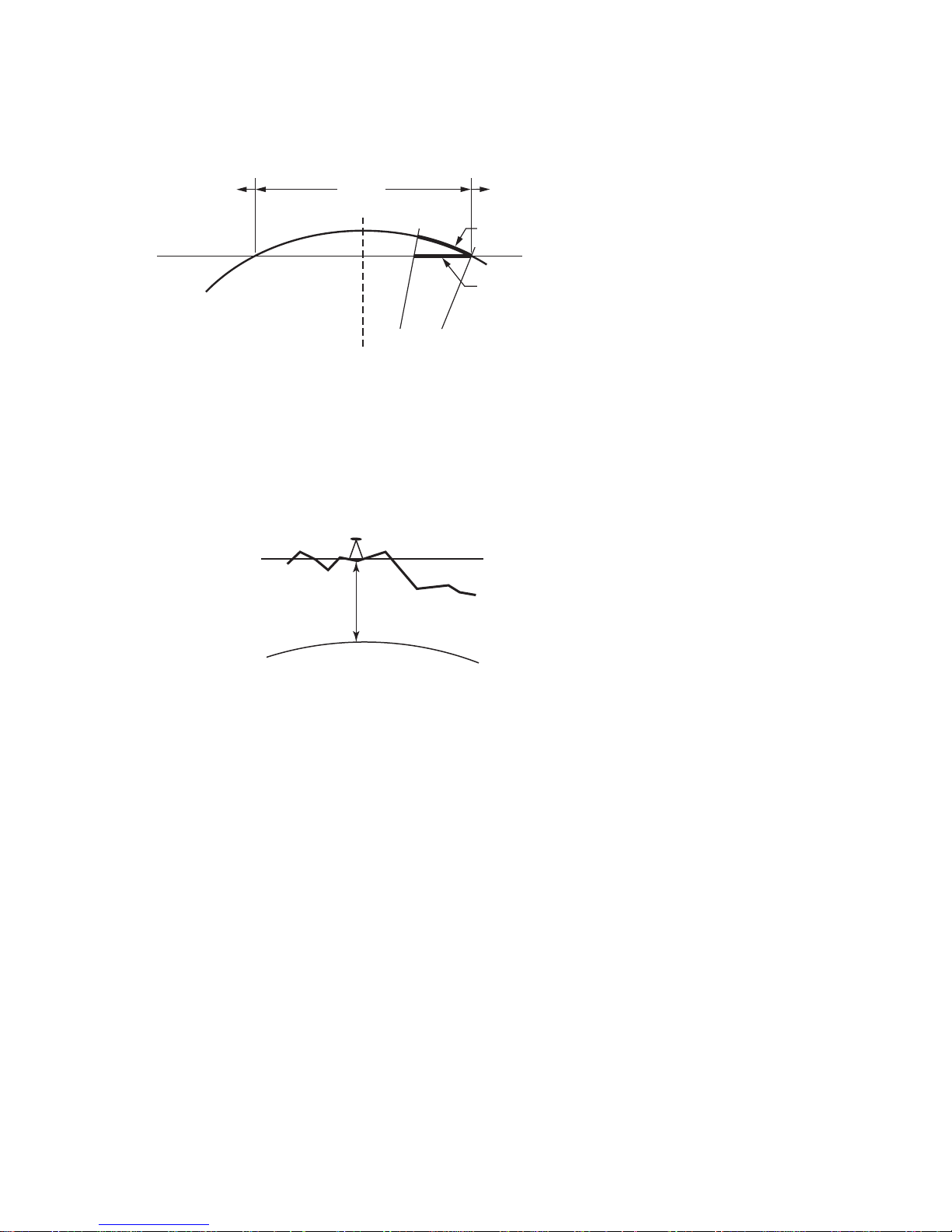
Survey Pro GPS User’s Manual
86
Fig. 3: Transverse Mercator Mapping Plane
A side view of the cylinder shows the effect of scale
distortion.
E
l
l
i
p
s
o
i
d
Mapping Plane
K=0.9996
K=1.0 K=1.0
Central Meridian
K>1.0
K>1.0
K<1.0
Distance on Ellipsoid
Distance on Map
Ellipsoid
Terrain
h
Mapping
Plane
• TDS Localization Stereographic Projection
The scale factor at the start location (usually the first GPS base
station in a project) is calculated for ground distances at the base
height. The scale factor increases more or less uni f orm ly in all
directions as you move away from the base. The scale factor does not
change appreciable within the range of RTK GP S, so this map
projection is an excellent way to m odel simple flat earth ground level
coordinate systems.
Fig. 4: Localization Stereographic Mapping Plane
A side view of the ellipsoid and stereographic mapping
plane show the scale calculated for ground distances at
the base hei
g
ht.
Page 87

GPS Coordinates
87
R+h
Radius of
Ellipsoid, R
Ellipsoid
Height, h
Distance on
Ground
Distance on
Ellipsoid
Ellipsoid Scale Factor
This scale factor accounts for the height of th e ground above the
reference surface (the ellipsoid). This scale factor is defined
geometrically: Consider t h e following diagram:
dist
ground
/(R+h) = dist
elip
/R
dist
elip
/dist
ground
= R/(R+h)
k
elip
= R/ (R+h)
Combined Scale Factor
Generally, the two scale factors are multiplied together into a
combined scale factor. The combined scal e factor is then applied to
grid distances to get ground distances:
k
cf
= k
elip
* k
map
dist
grid
= dist
ground
* k
cf
Fig. 5: Ellipsoid Scale Factor
The effect of height above the ellipsoid on scale.
Page 88

Survey Pro GPS User’s Manual
88
Vertical Coordinate Systems
GPS measurements provide ellipsoid heights. Most survey projects
require orthometric elevations. To convert heights into elevations,
you need to correct for the difference between the surface of the
reference ellipsoid and the level surfac e representing the gravity
field.
The procedure to convert heights (h) to elevations (H) involves the use
of a geoid model. The geoid is a theoretical surface that approximates
mean sea level. If one knows the separation between the reference
ellipsoid and the geoid, called the geoid undulation (N), then one can
determine orthometric elevations from ellipsoidal heights.
Geoid Models in TDS Software
Survey Pro has several geoid models in the coord inate system
database. All of the geoid models use data f iles in geoid grid file
(*.GGF) format.
Note: To use a geoid model, geoid data files (*.GGF) must be in the
Geodata directory.
• In the U.S.A., Mexico, and the Caribbe an you can use the NGS
Geoid96 or the NGS Geoid99 models. This coverage includes the
continental United States, Alaska, Hawaii, Mexic o, and the
Caribbean.
Terrain
Geoid
Ellipsoid
H
N
h
h=H+N
Fig. 6: The Height Equation
Page 89

GPS Coordinates
89
• In the continental USA you can use the new NGS Geoid03 model.
• In Canada you can use the Geodetic Survey Division HT 2.0
model, or the older GSD95, HT1_01, and HT97 models.
• For any location world wide, you can use the NIMA 15-minute
geoid height grid data file, WW15mGH.*. This file covers the
entire globe on a 15’ x 15’ grid.
• In Australia you can use the AUSGEOID98 geoid model.
Note: To use any of these geoids with Survey Pro, you need files in
Trimble .ggf format. For the US, Canadian, and EGM geoid models,
you can convert the files from their ori ginal format into .ggf format
using the Geoid File Convert and Sub Grid function in
ForesightDXM. The Australian AUSGEOID98 mod el is n ot
supported in this function, so this data is availabl e in six overlapping
sub grid files already in .ggf format. All of the source files are
included on the TDS Works CD in the \Geodata directory. Also, you
can download data from the TDS web site on the GPS page.
Page 90

Page 91

91
Tutorial Jobs
This section contains sample jobs to illustrate all of the main
functions of Survey Pro GPS Module. Each job illustrates different
horizontal and vertical projection m ethods as well as different GPS
field procedures.
Before Starting
• Make sure you have the file demofile.txt in the same directory as
the Survey Pro executable (usually in Disk\Program
Files\Survey Pro or Built In Storage\Program F iles\Survey Pro).
• Make sure you have the files TDSControl_Gr ound.job and
TDSControl_ORNorth.job loaded on the data collector.
• Make sure you have the geoid files Oregon G99.ggf and North
America EGM96.ggf in the geodata directory ( \Disk\Geodata for
the Ranger and \Built in Storage\Geod ata o n the Recon).
• Make sure the Standard and GPS modules are registered.
• Make sure you are in GPS Mode, and make sure Demo Mo de is
the current active instrument
Starting a New Job: One Point Localization
Scenario
You show up at a new job site where no previous coord inat es e xi s t.
You want to use RTK to create a new ground level coordinate system
for a legal and topo survey.
Objectives
This tutorial job will teach you:
¾ How to start a new job with one point and begin measuring ground
level distances without any existing control.
¾ How to set the base and rover receivers
¾ How to collect data points
¾ How to check to existing points.
Procedure
Page 92
Survey Pro GPS User’s Manual
92
1. Create a new job.
• Enter Point Name 2 as the starting point and enter a starting
location of (5000, 5000, 100).
2. Set the base and rover.
• Go to Start GPS Survey
, choose Start Survey with One Point
Setup>.
• Choose Set New Base and ‘connect’ to the Demo Mode
receiver. A simulated autonomous base position is rece ived,
and you can Set the base.
• Connect to the Demo Mode rover, Set the Rover.
• You are now ready to collect data in your new coordinate
system.
3. Data collect points 3,4,54, and CHAP.
4. Move the base receiver to a different setup.
• Go to Start GPS Survey
, choose Set New Base.
• Pick point 54, tap Next > and Set to set the base. Tap Set to
set the rover.
• You are now ready to collect data from this setup.
5. Check a point to verify setup and solution.
• Tap Control to open the Control Points screen. Occ upy points
CHAP and 3 as Check points. The results should be perfect.
Existing Job: Ground – TDS Localization
Scenario
You have already done a job at an existing site. The original job was
completed with a closed traverse starti ng from of an assumed
bearing, so there is no projection and no datum to define the local
coordinate system. You want to measure new points on this site with
your RTK GPS equipment, and calculate coordinates in the original
local system.
Page 93

Tutorial Jobs
93
Objectives
This tutorial job will teach you:
¾ How to start a job from a control file.
¾ How to set the RTK base and rover.
¾ How to occupy control points and solve a localization adjustment in
Ground – TDS Localization mode.
¾ How to move the base station receiver to existing local points.
Procedure
1. Open a new job and import control points.
• Open a new job, tap Import a Control File and select
TDSControl_Ground.job.
2. Start the Survey from a new autonomous base.
• Go to Start GPS Survey
, the first step will be the Choose
Projection Mode screen. Since you ha ve a local ground level
coordinate system with no projection and no datum, tap Use
Ground – TDS Localization.
• Tap Set New Base to ‘connect’ to the Demo Mode receiver.
Before connecting, tap Receiver Settings and go to the Post
Process card to turn on the Recording Interval.
• Enter a new point name for the Base Point Tap Next> and
then Set to set the base and configure the reference position
in Survey Pro.
• Connect to the Demo Mode rover and tap Set Rover> to
complete equipment setup
3. Collect c ontrol points.
• Tap Collect Control> to open the Control Points
screen..
• Occupy the existing points 2 and CHAP as GPS control points
by entering their names in the Point control and ta pping
Control.
Page 94

Survey Pro GPS User’s Manual
94
Note: Because you imported points as job file control points, you will
see a message that GPS control point collection wil l m odify the job file
control point. Geodetic coordinates will be added to the plane only
point. Tap OK at this warning.
• You will see a prompt telling you now have enough points for
the localization adjustment. You can choose to Solve
Localization, or you can Collect more control. It is usually
advisable to collect at least more control point than the
minimum required so you have some redundancy in your
solution.
• Occupy 54 as an additional GPS control point.
4. Solve the localization adjustment.
• Tap Projection and then Solve Localization… to open the Solve
Localization wizard. Your three control points are selected as
horizontal and vertical adjustment points in the list.
• Tap Solve> to calculate the localization adjustment and
display the residual/misclosure valu es for each point. In this
case, the residuals are all 0.0, since the measurements were
simulated and mathematically perfect.
• Tap Next> to examine the solution parameters.
• The scale is 0.9999972. This is approximately –2.2 ppm,
or less than 3mm in 1Km, and would be considered near
perfect. Solutions using actual field measurements will
usually have a scale around 15-25 ppm.
• The rotation is 1-57-47. You may or may not be able to
evaluate this answer. In this example, the ground
coordinates were created by scaling Or egon North map
projection coordinates, so the rotation is the negative of
the meridian convergence on that mapping plane zone. In
other jobs, the bearings may have arbitrary orientation,
Page 95

Tutorial Jobs
95
in which case the rotation value will adjust to the local
bearings.
• The Delta values represent the shift from the TDS default
stereographic zone false northing and easting (100000.0,
100000.0) to the local system (5000.0, 5000.0).
• Tap Accept to complete the wizard. The Adjust with
Projection wizard will adjust the job with the new coordinate
system and display a preview. In this case, you will see the
new base point updated. You can tap Show all points to see
which job file points were not adjusted and why.
5. Check points.
• The Data Collection
screen is open and you are ready to
collect data in your local coordinate system. However, before
you begin, it is advisable to check to an additional control
point to verify the solution. Tap Cont rol to open the Control
Points screen.
• Enter Point 3 and tap Check. Results should be perfect in our
example. In the field you would expect check points to be
within the measurement precision of your GPS syst em.
• Tap Accept and review the results on the Results
tab.
• Tap Close to return to the Data Collection screen.
6. Collect some points with maximum precision
• Enter a starting point number. For this example, enter b1.
Tap Point to ‘measure’ the point, the Occupy Data Point
screen opens and the session on this point is timed. Tap
Store SS when you have occupied the point for the desired
length of time. This is the most precise way to collect a data
point.
7. Collect an a dditional observation to a point in the post processing
log file.
• Tap Post Process to open the RTK Rover Session
screen. The
point name of the last point collected is the default name in
the Site ID field.
Page 96

Survey Pro GPS User’s Manual
96
• Set the Duration to 1 minute and tap Start. When the session
is over, you will hear a beep. You can close the Re ceiver
Session screen.
8. Collect some quick points.
• Enter a new point range, say 301, and tap Store SS. This is
the quickest way to store a point, although the measurement
is slightly less precise than if you occupy the data point.
9. Collect some feature points.
• Tap Feature to open the Feature Collection
screen. Using a
Time Interval of 5 seconds, tap Start to open the Occupy Data
Point screen.
• Tap Start to begin continuous collection, you will be prompted
for a description, feature, and attribute (depending on your
Survey settings) for this first point. All additiona l points will
be stored with these properties.
• Store a few points, then tap Done
• Tap Feature again, this time choose the Manual: prompt every
point method. Tap Start to open the Occupy Data Point
screen.
• Tap Store SS to store each point, you will be prompted for the
properties of each point stored.
10. Move the base to a point in the coordinate file measured with
GPS.
• Close the Data Collection
screen, and tap Start GPS Survey.
• Tap Set New Base>, and enter Chap as the Base Point.
• Tap SET to set the base and configure the base p osi tion in
Survey Pro. Tap Set Rover> to set the rover.
• The coordinate system is already solved, so you ar e ready to
collect data. The Data Collection
screen opens.
11. Check points and add more GPS control points.
Page 97

Tutorial Jobs
97
• Tap Control to open the Control Points
screen. Select point 52
and tap Check. The results should be perfect.
12. Move the base to a point in the coordinate file not measured with
GPS.
• Tap close to close the Data Coll ection
screen, and open Start
GPS Survey again. Tap Set New Base>
• Choose point 1 as the Base Point. Tap Next> and you are
prompted to compute the geodetic coordinates from the plane
coordinates using the current coordinate syst em . Tap OK.
Note: This action is equivalent to the TDS “Move Base” routine in the
DOS software.
• The geodetic coordinates for point 1 are computed. Tap SET
to set the base and configure base position in Survey Pro.
• Tap Set Rover> to finish equipment setup. Because the
coordinate system is already solved, the Data Collection
screen opens and you are ready to collect m ore points.
13. Check points.
• Tap Control to open the Control Points
screen. Select point
CHAP and tap Check. The results should be perfect.
14. Collect more data
• You are now ready to add more points to the job.
Reuse Localization Solutions
Scenario
You want to return to the project site from the previous tutorial to
add some new measurements. You want to use a new job file for this
new work, but you want to reuse the coordinat e system you ha ve
already solved without the need to occ u py the control points again.
Objectives
This tutorial job will teach you:
Page 98

Survey Pro GPS User’s Manual
98
• How to export a job file of selected points.
• How to reuse a localization solution from a control file.
• How to solve a fixed scale horizontal adjustment.
• How to save and select a localization solution to the coordinate
system database.
• How to use the Adjust with Projection wizard when updating the
coordinate system site.
Procedure
1. With the job from the previous tutorial open, create a new job to
use for a control file on this site.
• Go to File
| Export and select .JOB as the file type to export
and tap Next>.
• Tap To/From and enter points 1-4,52,54,chap,new. Tap
Export and save the file.
2. Open a new job with the control file created.
• Go to File
| Open/New. Create a new job, selecting the file
you just exported as the control file.
• At the prompt to set the coordinate sy stem, tap Yes. The
localization solution solved in the prev ious tutorial is set for
this job.
3. Assuming your base is set up, you can go directly to rover setup.
• Open the Start GPS Survey
wizard and select Use Remote
Base>. Tap Set Rover>.
• The base reference position is received over the radio link,
and Survey Pro finds your original base po int. T a p Next>
and Set to complete GPS Setup.
• The Data Collection screen opens and you are ready to collect
data
4. Check point
• Tap Control, and select point 1 to occupy as a Check. The
results should be near perfect.
Page 99

Tutorial Jobs
99
5. Data Coll ection
• Occupy b1,b2,b4,bChap,bMane as data collection points.
6. Resolve the horizontal localization adjustment with a fixed scale
adjustment
• Tap Control, Projection, Solve Localization to open the Solve
Localization wizard.
• Tap Solve Rotation Only to constrain this adjustment to fix the
scale to 1.0. You can use only two points with a fixed scale
adjustment, so select 2 and CHAP as horizontal control. Tap
Solve> to open the Residuals screen.
• The horizontal solution is now unique, so the misclosures to
the points not used in the solution are show. Re view these
results and tap Next> to open the Results screen
• The results now indicate a scale of 1.0, and the same rotation
you had before. Tap Accept to open the Adjust with
Projection wizard and preview the changes t o the p oin ts.
Mapping Plane with Ground Coordinates
Scenario
You need to lay out a petroleum well site at coordinates specified in a
US State Plane map projection zone. You wish to use your RTK GPS
to do the stake out, but the site may require some tota l station
measurements to collect points not accessible with GPS. You want to
be able to work with your job file points in both the map projection
grid coordinates and in ground level coordinat es.
Objectives
This tutorial job will teach you:
• How to start a job and import ASCII coordinates.
• How to start a survey and select a map projection zone.
• How to do a mapping plane localization.
• How to use GPS Stake Out.
• How to use the Ground Coordinates setup.
• How take conventional measurements on the ground with a
selected map projection zone.
Page 100

Survey Pro GPS User’s Manual
100
• How to switch from Ground Coordinates back to grid coordinates.
• How to set the survey scale factor for a point on a map projection.
• How to use the survey scale factor when storing COGO points on a
map projection grid.
Procedure
1. Start a new job.
• Choose not to use a control file. Use point 1 and accept
default starting coordinate.
2. Import contr ol coordinates from ASCII file
• Go to File
| Import, and set the type to Text files .csv. Select
TdsControl_Oregon North metric.csv.
• Create a layer named CONTROL to import the points onto.
This will protect these points as job file control.
3. Start a mapping plan e survey.
• Go to Stakeout
| Stake Points to open the Start GPS Survey
wizard. Choose to Select a Mapping plane zone> to open the
Select Coordinate System screen. Choose US State Plane 83
zone Oregon North 3601. The default geoid is Geoid99, but
you can also select Geoid03, or EGM96.
• Tap Finish to set the coordinate system. Because you selected
a new coordinate system, the Adjust with Pr oj ection wizard
will run. In our example, our imported ASCII points have
only plane locations, so no job points will be updated. Tap
Next> and you will see a message that no job points would be
changed by the adjustment. You can review the report
anyway, or just tap Apply to finish setting the coordinate
system.
4. Set the base and rover.
• Select Set New Base>, ‘connect’ to the Demo Mode base
receiver. Enter ‘new’ for the name of the base po int and tap
Next> to start the survey from an autonomous position. Tap
 Loading...