


TRIPLEX
4/8 CHANNEL
BASIC/NETWORK
USER’S MANUAL
Thank you for purchasing the product.
We recommend users who install and operate the unit to thoroughly read this manual and other
reference manuals indicated in this manual before installation and operation.
The pictures can be different from real system according to specification.
This user’s manual is based on Triplex 4/8 Channel Basic/Network Series. Triplex 4/8 Channel Ba-
sic model support USB socket as a basic backup device, it does not support network function.
Network function is only supported on Triplex 4/8 Channel Network model.
This user’s manual and the software of Triplex 4/8 Channel Basic/Network are protected by COPY-
RIGHT LAW.

2/65
GENERAL SAFETY AND PRECAUTIONS
This model is manufactured to safety international safety standard. Review
the following safety precaution to avoid injury and prevent damage to the
DVR or any products connected to it.
1. Use a proper power source.
Do not operate this product from a power source that applies more
than the specified voltage (90~260 VAC).
2. Never insert metallic material into the DVR case. This can cause
electric shock.
3. Do not operate in wet & dusty condition. Keep product surfaces clean
and dry.
Avoid placing the DVR in areas like a damp basement or a dusty hallway.
4. Do not expose this product to rain or use near water.
If the product gets wet, unplug it and contact an authorized dealer
immediately.
5. To clean the outside case of the DVR, use a lightly dampened cloth
(no solvents).
6. The DVR generates heat during operation. Place the DVR in a well
ventilated area. The DVR has a built in fan to properly ventilate the system.
Do not block air bent holes (bottom, upper, sides and back) of the DVR
case.
7 Do not operate with suspected failures. If there are any unusual
sounds or smells coming from the DVR, unplug it immediately and contact
an authorized dealer or service center.

3/65
8. Do not attempt to remove the top cover.
Warning: Removing the cover of DVR can cause severe electrical
shock.
9. Use standard lithium cell battery. NOTE: Battery is installed in the
system.
The standard lithium cell 3V battery located on the mother board
should be replaced if the time clock does not hold its time after the power
is turned off.
Warning: Unplug the DVR before replacing battery or you may
be subjected to severe electrical shock. Properly dispose of old batteries.
Caution: Risk of explosion if battery is replaced by an incorrect
type. Do not discard lithium batteries into the trash can or into fire. Dis-
pose in accordance with local waste regulations.
10. Some DVR models use a DC adapter because the power supply is
outside the DVR cabinet.
Use only the DC adapter that is supplied.

4/65
FCC COMPLIANCE STATEMENT
Caution: Any changes or modifications in construction of this device which
are not expressly approved the party responsible for compliance could
void the user's authority to operate the equipment.
NOTE:
This equipment has been tested and found to comply with for a
Class A digital device, pursuant to part 15 of the FCC Rules. These limits
are designed to provide reasonable protection against harmful interference
when the equipment is operated in a commercial environment. This
equipment generates, uses, and can radiate radio frequency energy and,
if not installed and used in accordance with the instruction manual, may
cause harmful interference to radio communications, Operation of this
equipment in a residential area is likely to cause harmful interference in
witch case the user will be required to correct the interference at this own
expense.

5/65
CONTENTS
1. SYSTEM COMPONENTS...................................................................................................................................... 7
2. THE NAME OF EACH SECTION........................................................................................................................ 8
2.1. FRONT PANEL.................................................................................................................................................. 8
2.2. REAR PANEL....................................................................................................................................................9
3. SYSTEM FUNCTION...........................................................................................................................................10
3.1. START.............................................................................................................................................................. 10
3.2. MONITORRING..............................................................................................................................................11
4. SETUP.....................................................................................................................................................................13
4.1. SETUP STRUCTURE AND INITIAL VALUE................................................................................................13
4.2. SETUP MENU.................................................................................................................................................. 15
4.2.1. CAMERA SETUP......................................................................................................................................15
4.2.2. RECORD...................................................................................................................................................17
4.2.3. SENSOR .................................................................................................................................................... 19
4.2.4. MOTION DETECTION.............................................................................................................................19
4.2.5. SCREEN....................................................................................................................................................21
4.2.6. AUDIO ...................................................................................................................................................... 21
4.2.7. SYSTEM.....................................................................................................................................................22
4.2.8. EXIT.......................................................................................................................................................... 31
5. RECORD FUNCTION..........................................................................................................................................32
6. SEARCH, PLAYBACK AND BACK-UP FUNCTION...................................................................................... 34
6.1. SEARCH FUNCTION......................................................................................................................................34
6.2. PLAYBACK FUNCTION................................................................................................................................35
6.3. BACKUP FUNCTION .....................................................................................................................................36
6.3.1. BACK-UP VIA USB MEMORY STICK ..................................................................................................... 37
6.3.2. BACK-UP VIA CD-R/W (OPTION) .......................................................................................................... 37
6.3.3. USE OF BACK-UP FUNCTION...............................................................................................................38
7. FIRMWARE UPGRADE......................................................................................................................................41
8. PTZ (PAN/TILT-ZOOM) CONTROL.................................................................................................................43
9. HOW TO USE A MOUSE.....................................................................................................................................44
10. CLIENT PROGRAM (8CH -VX8TFN2 VIEWER, 4CH- VX4TFN2 VIEWER) ..........................................45

6/65
10.1. PLAYER MODE ............................................................................................................................................46
10.1.1. PLAYBACK METHOD............................................................................................................................46
10.1.2. PLAYER MENU ...................................................................................................................................... 47
10.2. VIEWER MODE ............................................................................................................................................ 53
10.2.1. CONNECT VIEWER NETWORK............................................................................................................53
10.2.2. VIEWER MENU......................................................................................................................................55
11. SPECIFICATION................................................................................................................................................62
12. RECOMMENDED HDD/CD-RW......................................................................................................................64
12.1. RECOMMENDED HDD................................................................................................................................64
12.2. RECOMMENDED CD-R/W.......................................................................................................................... 64
13. WARRANTY AND DISCLAIMER ...................................................................................................................65
7/65
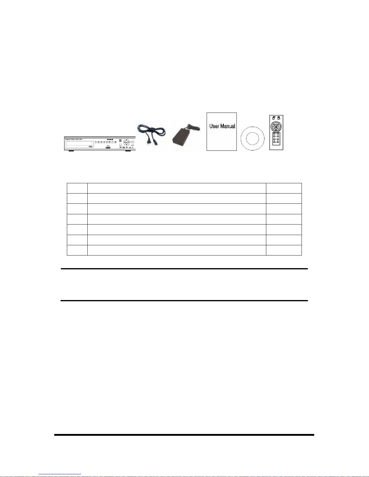
1. SYSTEM COMPONENTS
Following picture shows the components of a system. Open the package and check the compo-
nents of the system.
1 2 3 4 5 6
NO Components Volume
1 DVR system 1
2 Power cord 1
3 AC-DC adapter 5A, 12V 1
4 User’s manual 1
5 CD (viewer and operation& installation guide) 1
6 IR remote control 1
Reference
In the case that the system or components have problems, contact with seller or a
customer service center. The components may not be identical to the picture shown
above.
8/65
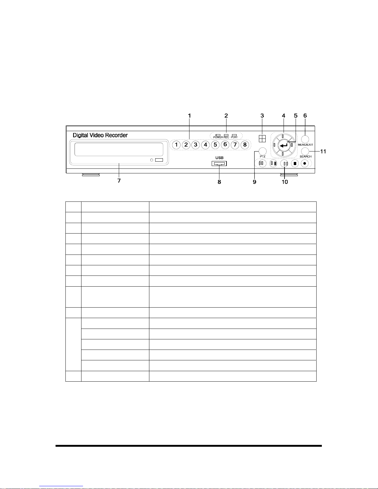
2. THE NAME OF EACH SECTION
2.1. FRONT PANEL
Each button of a system on front panel has below function.
NO. Name Function
1 Channel Choose channel what you want to see.
2 LED LED for Power, recording, playback.
3 REMOCON Receive IR remote control signal
4 CURSOR Menu direction button of left, right, up, down button.
5 ENTER Selection button.
6 MENU/EXIT Menu/ Exit Button.
7 CD-R/W CD-R/W (option item) for data back-up.
8 USB
USB Socket for Data back-up/ firmware upgrade.
(Used Only USB Memory Stick.)
9 PTZ PTZ mode On/Off.
REW Rewind.
PLAY/PAUSE Playback/ Pause.
FF Fast forward.
STOP Stop.
10
RECORD Record.
11 SEARCH Time Search.

9/65
2.2. REAR PANEL
NO.
Name of
connection part
Function
1 VGA Video output port for LCD/Computer monitor.
2 LAN
Port for connecting LAN cable.
(Except 4/8 Channel Basic Model)
3 RJ11 Controls DVR system.
4 VIDEO OUT Port for video output.
5 AUDIO IN,OUT Port for Audio in/output.
6 VIDEO IN Port for video input.
7 PS/2
Port for mouse that controls screen.
Control screen by using mouse.
8
Video
conversion switch
Switch for converting video mode to NTSC/PAL.
9
ALARM/SENSOR
/PTZ
Control port for alarm, sensor devices and PTZ camera.
10 POWER IN Port for power adaptor.(DC 5A, 12V)
11 Power switch Power Switch

10/65
3. SYSTEM FUNCTION
3.1. START
To connect system with camera and power adaptor on the rear panel of system. After system con-
nection is completed, the system itself tests its condition when power is on. The contents of self
test are HDD installation status, formatting for new HDD, CD-R/W installation status. Incase, Unex-
pected power off during recording is checked and system records automatically.
You can install max. two HDDs in the DVR system. (When CD-R/W is used then one HDD is can be
used only) The HDD storage capacity and model name is shown on the screen when DVR system
recognize the HDD. If the DVR system can not recognize HDD, DVR system does not booting. If
the HDD is not recognized, please install the HDD in order. If the problem appears continuously,
please contact to A/S center.
If you use new HDD in DVR system, the system asks you to format new HDD or not after recogniz-
ing the HDD. If you put the [PLAY] button, the HDD will be formatted. The formatted HDD is not
recognized on Personal Computer. Please be notice when you install new HDD.
Reference
If model and quantity of equipped HDD is not shown on HDD test screen, HDD con-
nection is wrong. In that case, User must check the connection of HDD with system.
In case, If you use only one HDD in the system, you must confirm that HDD must be
set to master by jumper. Please check the jumper is set on MASTER. Otherwise,
system can not boot.
You can use max. two HDDs in the system, one of then should be set to slave by
jumper.
RTC (REAL TIME CLOCK) CHIP keeps the system information. If the battery for RTC is discharged,
the system sets to default (factory) value again. Please check the Battery. Users see factory value
in setup section.
After system finish initial test and set up, the screen will be changed to 9 Split screen status. How-
ever, the system has unexpected POWER OFF during recording, the system will be rebooted when
the power on, and continued to record automatically.
11/65
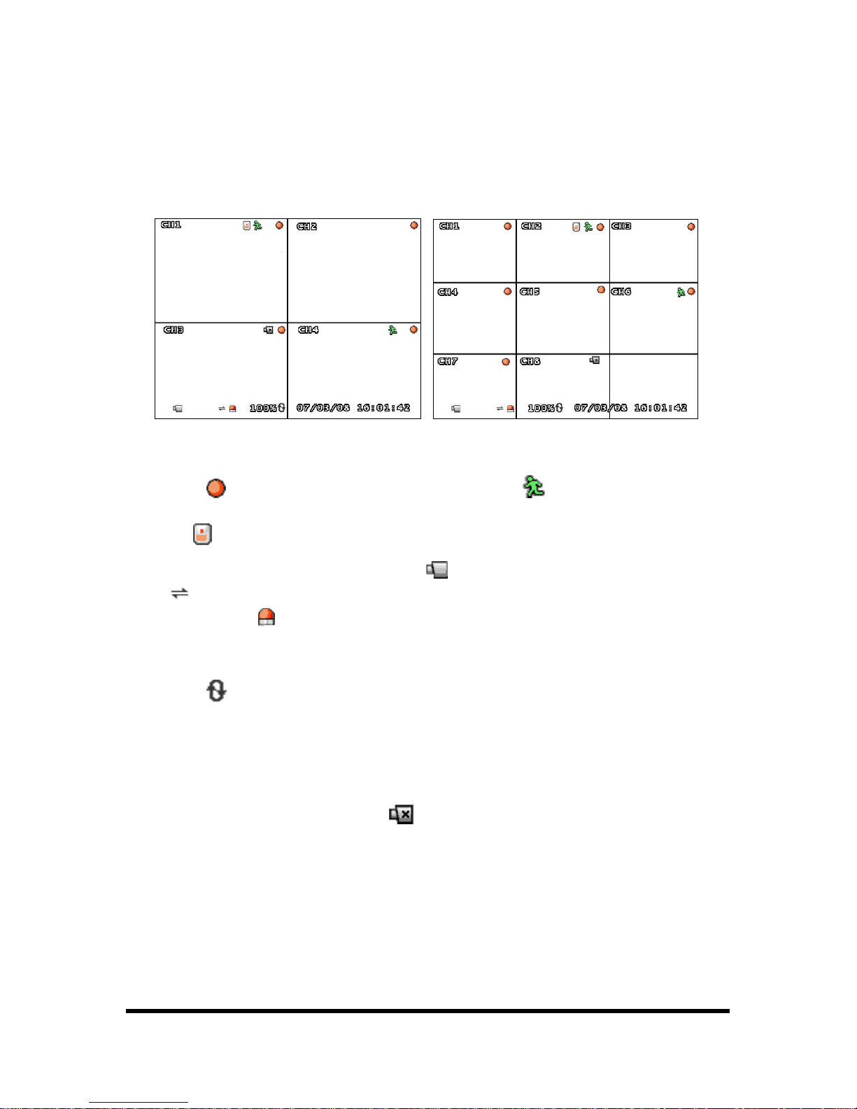
3.2. MONITORRING
The basic information of system is indicated on the lower part of monitor.
Quad monitoring screen < 4 CH > 9 Split monitoring screen < 8 CH >
A symbol indicates record status on current HDD. A symbol indicates motion sensor. A
symbol indicates that sensor is set on system and activated. The lower part of full screen in
DVR shows whole condition of system. A symbol
indicates that DVR monitoring mode. A sym-
bol
indicates that system is connected with user using client program on computer through
network. A symbol
indicates that alarm is set on system and activated. A symbol % indicated
that the capacity of HDD used.
A symbol
indicates on right of % indicates that 100% of HDD, then it erases data from HDD
and records data at the same time. In this condition, HDD has always full of data 100%. [07/03/08
16:01:42] shows time of system.
The system recognizes Video input signal automatically and system shows video source on screen.
In case of no input signal, system shows
mark on screen. But if the camera has connected
with system and shows blue screen, please check the connection between system and cameras.
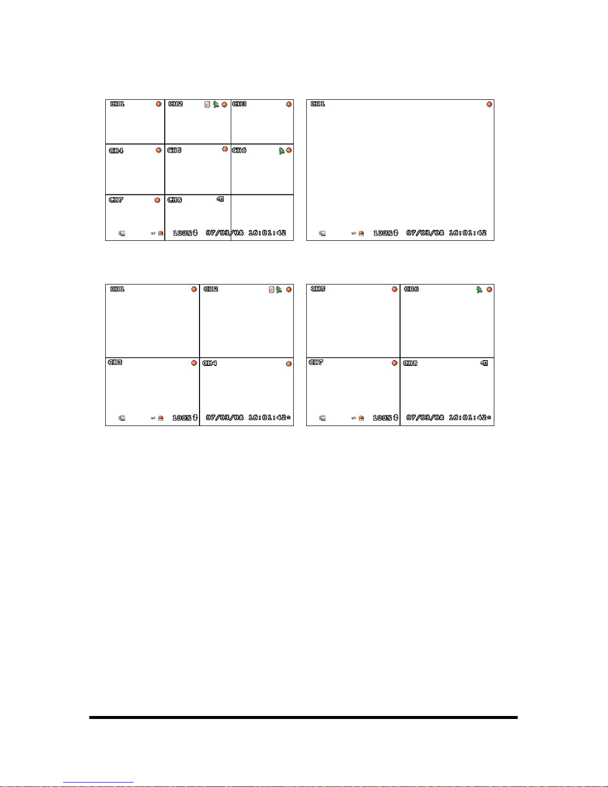
Press the channel button, the selected channel shows on entire screen. If you want to show 9-split
screen, press the [ENTER] button.
12/65
9 Split screen Full screen
1~ 4 CH Quad screen 5~ 8 CH Quad screen
If you press CH1 button twice, screen is changed to Quad screen of 1~4CH, and then press CH5
twice, screen is changed to Quad screen of 5~8CH. (only for 8CH DVR)

13/65
4. SETUP
4.1. SETUP STRUCTURE AND INITIAL VALUE
This system has selection menu and initial value composed as below table.
SETUP FACTORY DEFAULT
CHANNEL 1
DISPLAY ON
CAMERA
BRIGHTNESS,CONTRAST,HUE,SATURATION -----|-----
RECORD SPEED 7 (4CH DVR 15FRAME)
RECORD QUALITY NORMAL
EVENT REC DURATION 10
RECORD
RECORD SCHEDULE -
ALARM DURATION OFF
SENSOR
SENSOR1/2/3/4 DISABLE
CHANNEL 1
SENSITIVITY OFF
ALARM DURATION OFF
MOTION
DETECTION
MOTION AREA -
BORDER ON
SCREEN
VIDEO ADJUSTMENT -
RECORD ON
MUTE OFF
INPUT VOLUME -----|-----
AUDIO
OUTPUT VOLUME -----|-----
OVERWRITE ENABLED YES HARD
DISK SETUP
FORMAT HDD -
PASSWORD
CHANGE
111111
TIME ZONE
(GMT+09:00)
[Seoul, Korea Standard Time]
TIME SET -
SYSTEM
TIME SET
SYNC. FROM NTP SERVER NO

14/65
NTP SERVER IP 203.117.180.36
DAY LIGHT SAVING TIME NO
SYSTEM
EVENT LIST
-
ENABLE NO
IP TYPE [STATIC]
IP ADDRESS 192.168.10.218
GATEWAY 192.168.10.1
NET MASK 255.255.255.0
PPPOE ID -
LOCAL IP
PPPOE
PASSWORD
-
PORT 8841
MAC ADDRESS 00:11:3D:XX:XX:XX
PASSWORD 111111
ENABLE ON/OFF NO
IP ADDRESS 222.231.24.28
PORT 9990
NAME
SERVER
DVR NAME -
NETWORK
VIDEO
QUALITY
HIGH HIGH
BAUDRATE 115200
DATA BIT 8
PARITY BIT NONE
RS485
STOP BIT 1
CHANNEL 1
ID 1
MODEL NONE
PAN/TILT
DEVICE
PAN/TILT TEST -
F/W UPGRADE -
LANGUAGE ENGLISH
15/65
4.2. SETUP MENU
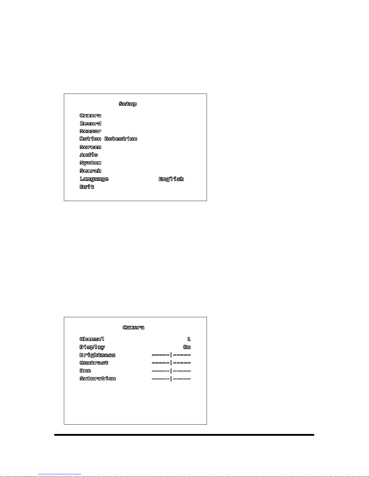
When user presses [MENU] button on front panel, the following screen is shown.
In the setup menu, user can move to each item and change item by pressing [▼, ▲] button. The
setup menus are [CAMERA, RECORD, SENSOR, MOTION DETECTION, SCREEN, AUDIO, SYSTEM,
SEARCH, LANGUAGE, and EXIT].
User presses [ENTER] button on setup to access sub menu. User presses [▲, ▼, ◄, ►] button
and [ENTER] button at the sub menu to get desired value. After that, presses [ENTER] button to
return previously menu.
4.2.1. CAMERA SETUP
User can change CAMERA SETUP.

16/65
4.2.1.1. CHANNEL
CH 1~4 can be selected. User can control the condition of image from camera.
4.2.1.2. DISPLAY
If users want to display camera screen, select as “ON”, if not select as “OFF”.
4.2.1.3. BRIGHTNESS
Adjust brightness of image. Users can adjust from 1 to 10 levels. The BAR [|] goes to left side, it
can be changed to dark. The BAR [|] goes to right side, it can be changed to bright.
4.2.1.4. CONTRAST
User can adjust screen’s contrast. User can adjust from 1 to 10 levels. As the BAR [|] goes to left
side, the contrast is lower. The BAR [|] goes to right side, the contrast is higher.
4.2.1.5. HUE
User can adjust hue level (from 1 to 10). The BAR [|] goes to left side, color tone is changed to
pale, The BAR [|] goes to right side, color tone is changed to deep.
4.2.1.6. SATURATION
User can adjust saturation level (from 1 to 10). The BAR [|] goes to left side, color tone is
changed to pale, As the BAR [|] goes to right side, color tone is changed to deep.
17/65
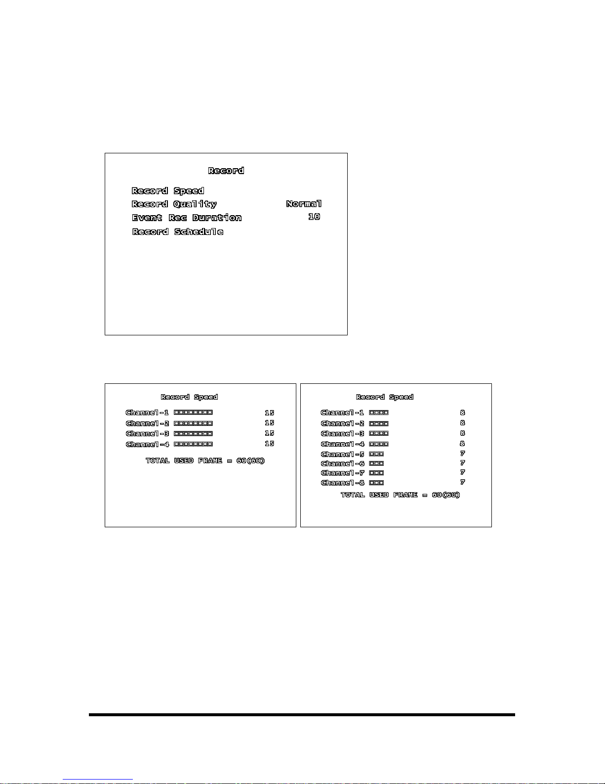
4.2.2. RECORD
User can change RECORD SETUP.
4.2.2.1. RECORD SPEED
< 4CH > < 8CH >
User can select FRAMERATE within 60 frames. Users can divide the frame rate according to their
importance.
4.2.2.2. RECORD QUALITY
To choose the video quality for recording, go to RECORD QUALITY. Then, use the ENTER (SE-
LECT) BUTTON to choose LOW, NORMAL or HIGH. The higher record quality, the cleaner image will
be shown during playback. The lower record quality saves more HDD storage space.
18/65
4.2.2.3. EVENT REC DURATION
User can select the time of EVENT (sensor / motion) record duration.
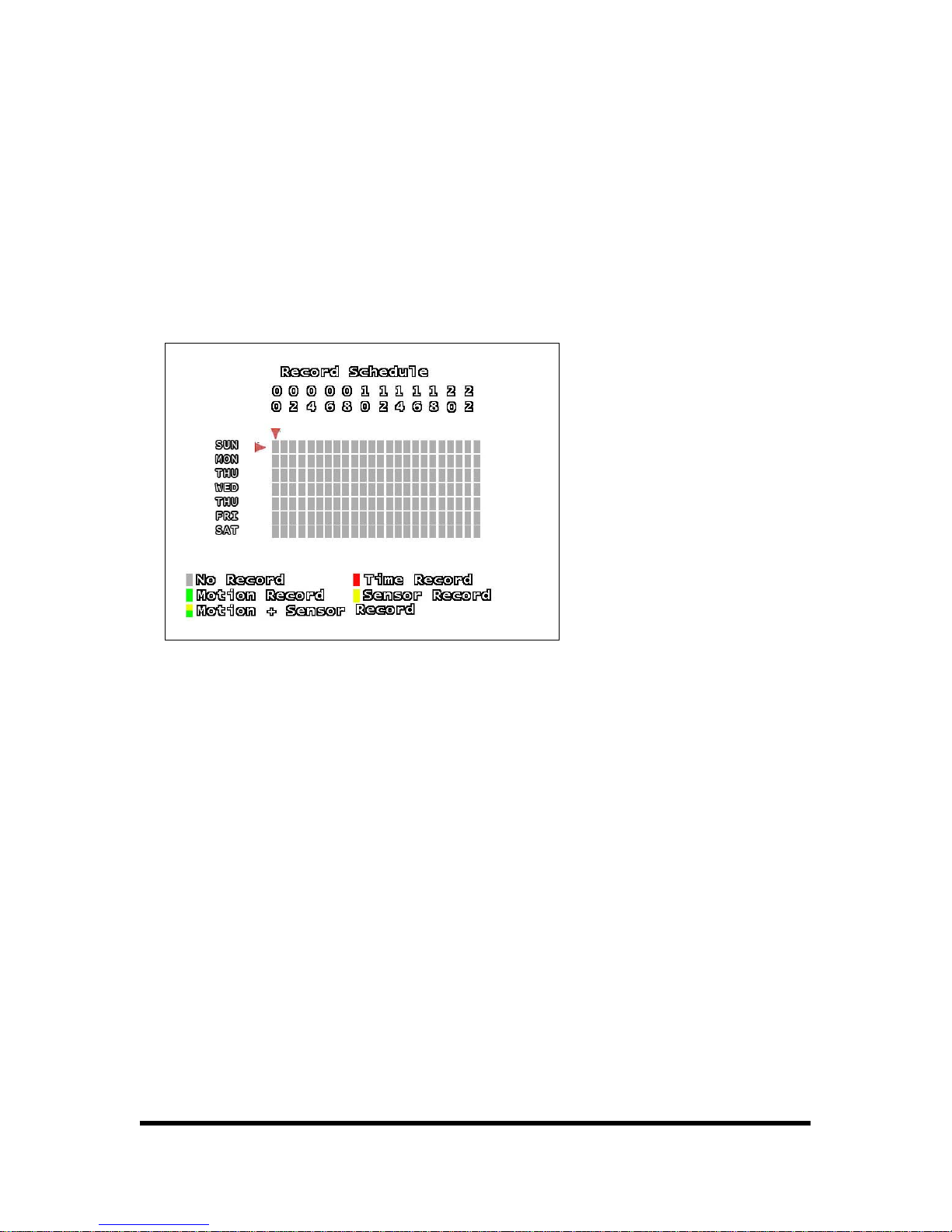
4.2.2.4. RECORD SCHEDULE
To schedule recording is based on a 24-hour clock, user can select the time of recording.
User can move cursor to desired time and select the type of recording by using [▲, ▼] button.
The No Record: System will not record data during this period.
The Time Record: System will record data continuously during this period.
The Motion Record: System will record data when the cameras recognize any motion in designated
area during this period.
The Sensor Record: System will record data when the systems recognize sensor/alarm during this
period.
The Motion + Sensor Record: System will record data when the systems recognize any motion and
sensor/alarm.
Press the [▲, ▼] button can make several record type and time, and press [ENTER] button to
make change whole schedule as one recording type and time.
19/65
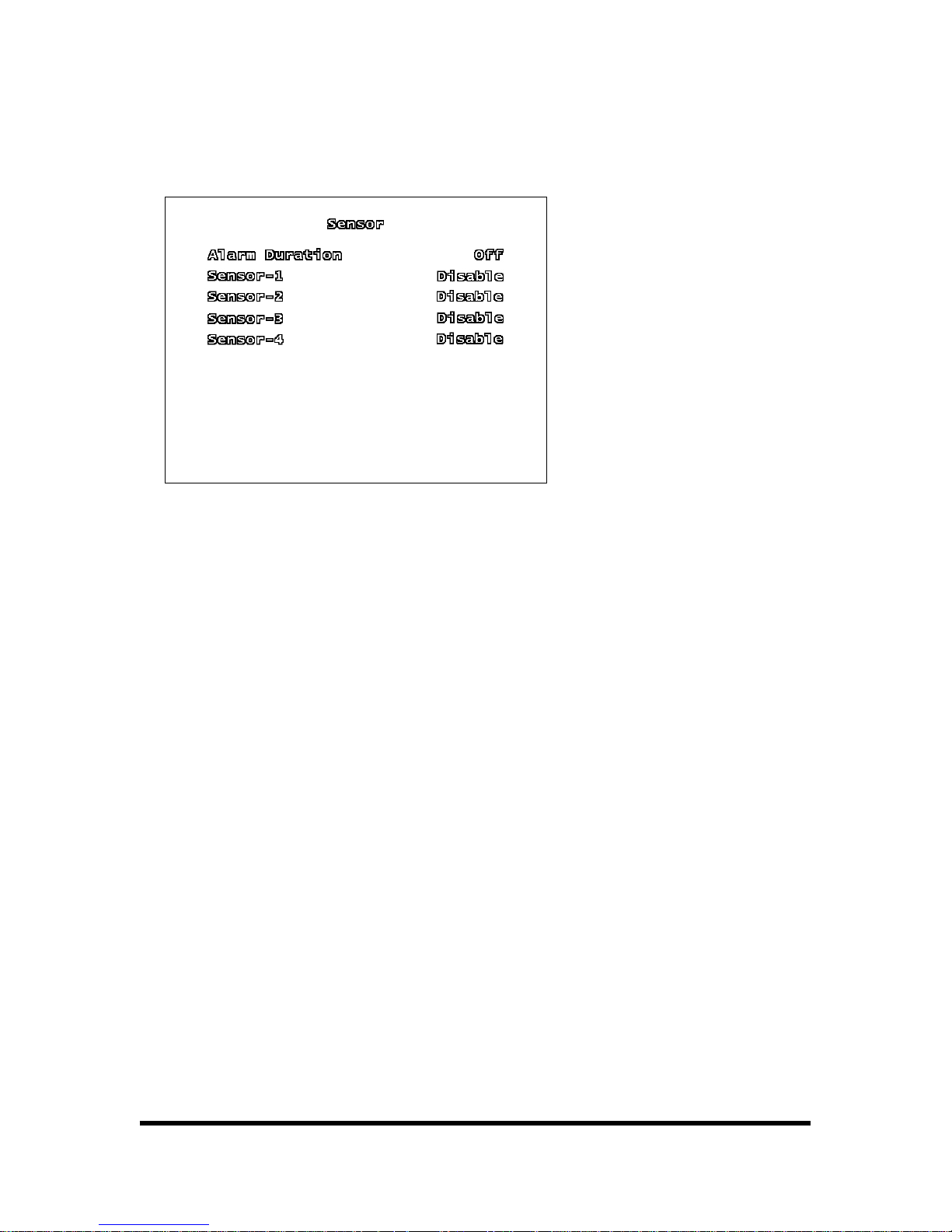
4.2.3. SENSOR
4.2.3.1. ALARM DURATION
It indicates how long the alarm lasts after it sets [OFF, 05, 10, 15, 20, 25, 30, CONT]. It sets the
alarm duration (in seconds) after alarm is activated. Select “DISABLE” to deactivate sensor re-
cording or if there is no sensor installed in DVR system. To continue the alarm signal on, to select
as CONT
4.2.3.2. SENSOR - 1, 2, 3, 4
Each channel has to be set by the type of SENSOR. The initial value is [DISABLE], you can select
[NORMAL OPEN TYPE/ NORMAL CLOSE TYPE].
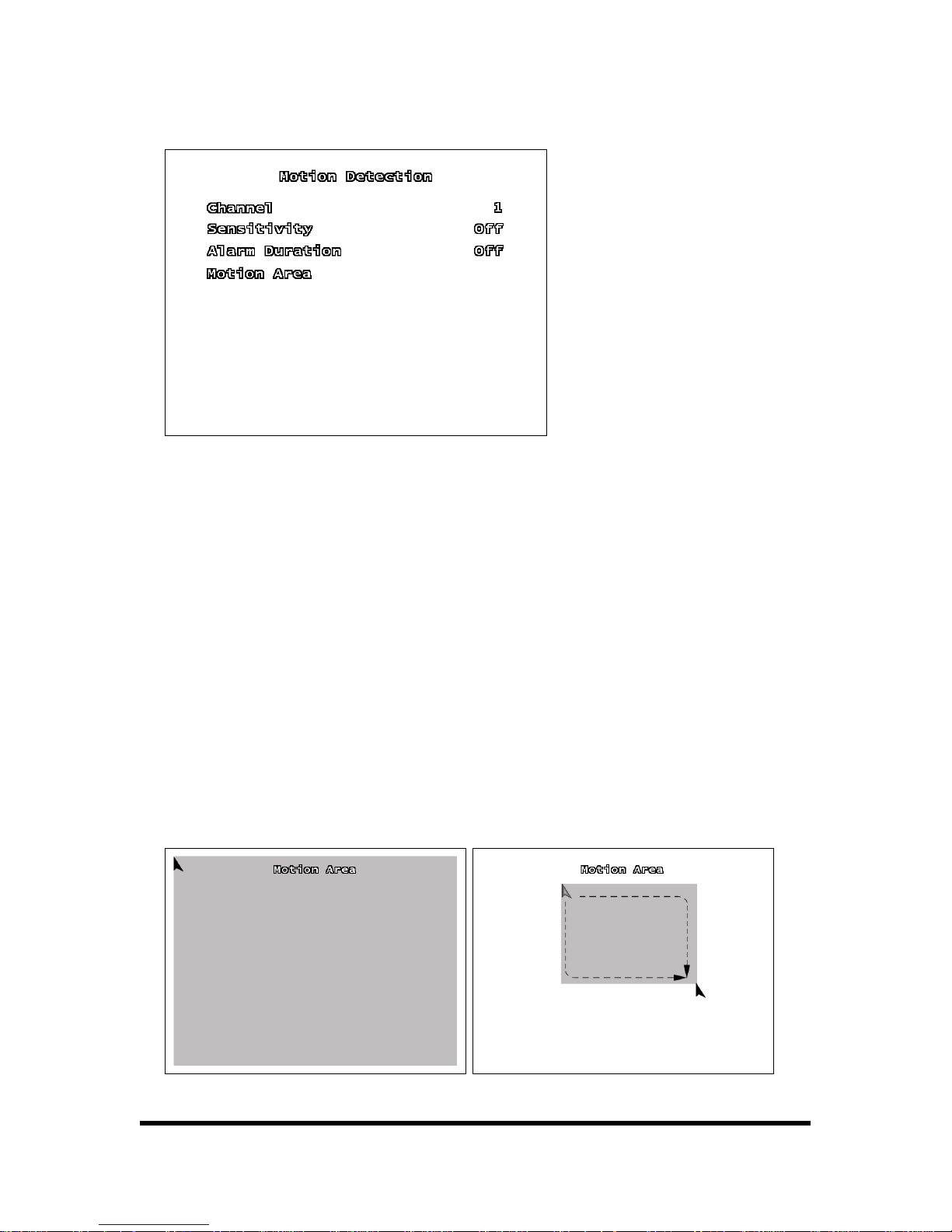
4.2.4. MOTION DETECTION
Select Motion detection. It is available when the system recognizes the movement.
20/65
4.2.4.1. CHANNEL
Select each channel for record.
4.2.4.2. SENSITIVITY
It adjusts the sensitivity of the built-in motion sensor on the DVR system while recording. The
higher the number, the higher the sensitivity is. In that case, record can be occurred by small noise.
4.2.4.3. ALARM DURATION
By changing the value in the Alarm duration, you can adjust how long the alarm will last in seconds.
User should installed alarm device in the system.
4.2.4.4. MOTION AREA
Follow the direction to select Motion area.

21/65
Locates cursor to start point using [▲, ▼, ◄, ►] button.
After pressing [ENTER] button locates cursor to end point using [▲, ▼, ◄, ►] button.
Press [ENTER] button again.
[Note] We recommend you to choose motion detection area carefully because only one area can
be selected.
[Using the mouse button]
Press left button of mouse and drag mouse to select motion detection area for record.
4.2.5. SCREEN
User can select the screen location and the line of quad channel’s border.
4.2.5.1. BORDER
You can make the white border line around each channel to appear or disappear by using this op-
tion to be on or off.
4.2.5.2. VIDEO ADJUSTMENT
You can move the entire video screen using up, down, left, and right key.
4.2.6. AUDIO
The option to adjust the Audio input/output of DVR system.

22/65
4.2.6.1. RECORD
Make the record “ON” to enable sound recording when a microphone device is attached in AUDIO
INPUT port on the system.
4.2.6.2. MUTE
Control the Audio output.
4.2.6.3. INPUT VOLUME
Adjust input volume level of sound.
4.2.6.4. OUTPUT VOLUME
Adjust output volume level of sound.
4.2.7. SYSTEM
In this menu, you can see the information of the hard disk drive installed on the system, change the
system password, and adjust current time on the system, initialize system and etc.

23/65
4.2.7.1. HARD DISK SETUP
Set up Hard Disk Drive condition.
The information of Hard Disk Drive is shown on the screen. TOTAL means the total capacity of HDD,
USED means the rate of HDD used.
▪ OVERWRITE ENABLE: If you choose YES, recording continues. However, recorded data in HDD is
erased gradually when HDD has no space to record.
▪ FORMAT HDD: If you format the hard disk drive, all the recorded data stored on the hard disk
drive will be deleted. Remind that the system has no restore option once the hard disk drive is for-
matted.

24/65
When you choose this option, the system will ask you password before formatting. The default
password is [111111].
4.2.7.2. PASSWORD CHANGE
Change the password of DVR system.
You can use a combination of any buttons on the DVR front panel to change a new password.
Press [ENTER] button to finish. The changing is finished properly, the message [PASSWORD
CHANGED] is shown on the screen.
4.2.7.3. TIME SET
Adjust the current date and time of system.
▪ TIME ZONE: You can adjust the current time through the internet time server.

25/65
▪ TIME SET: To move the cursor on the screen, [▲, ▼] button on the front panel press [ENTER]
button to move desired date and time and [▲, ▼] to change number.
▪ APPLY: After adjusting the time, you have to move the cursor to APPLY, press [ENTER] button to
apply new time information.
▪ SYNC. FROM NTP SERVER: Connect to internet time server. If not you can not use SYNC. FROM
NTP SERVER.
▪ NTP SERVER IP: Input the internet time server’s IP address. The default value is [203.117.180.36].
Do not change the IP address except special occasion.
▪ DAY LIGHT SAVING TIME: Summer Time can advance the time by one hour from standard time.
This function is for user to use day time effectively. “Yes” for Summer time or “No” for Standard
time.
4.2.7.4. EVENT LIST
EVENT LIST function enables playback by event. The EVENT LIST on menu, it shows all past activi-
ties of system operation such as power on/off, recording start/stop, sensor on/off and etc showing
recording year/date/time in list. Play by EVENT LIST, using [▲, ▼] button, select the event that you
want to playback and press [ENTER] button. It playbacks the recorded video data.
4.2.7.5. NETWORK
You need to set the information regarding to NETWORK. The working about NETWORK setting is
need to professional’s guide, if not you may not use the Network function. Please be notice that.

26/65
▪ ENABLE: You have to set [ENABLE] is [ON], in order to connect to DVR system through Network.
▪ LOCAL IP: It contains several options to use network. Press [ENTER] button, you can move to
lower grade menu.
<IP TYPE> There are three different network connection types. Press [◄, ►] button to change IP
TYPE.
[DHCP TYPE]
[DHCP TYPE] – Press [◄, ►] button to select [DHCP], then press [MENU] button to show [LOCAL
IP] part. Move [EXIT], then select [EXIT & SAVE CHANGE] to finish Setup.
Reference
If you input PPPOEID and PPPOE PASSWORD, you can get the IP ADDRESS, SUBNET
MASK, GATEWAY automatically. You must ask installer IP TYPE before DVR is in-
stalled.

27/65
[PPPOE TYPE]
[PPPOE TYPE] – Press [◄, ►] button to select [PPPOE].
PPPOE ID: Use [▲, ▼] button to move [PPPOE ID], then press[ENTER] button to show keypad
pop-up window. Use [◄, ►,▲, ▼] button to move desired a number or a character, then press
the [ENTER] button.
PPPOE PASSWORD: Use [▲, ▼] button to move [PPPOE PASSWORD], then press [ENTER] but-
ton to show keypad pop-up window. Use [◄, ►,▲, ▼] button to select desired a number or a
character, then press [ENTER] button.
When you finish set-up, press [MENU] button to show [LOCAL IP]. [EXIT & SAVE CHANGES] to
finish set-up after you move [EXIT].

28/65
[STATIC TYPE]
[STATIC TYPE] – Press [◄, ►] button to select [STATIC]
IP ADDRESS: If you select IP TYPE as STATIC, you can input the IP ADDRESS yourself. Use [◄, ►]
button to move desired position, then press [▲, ▼] button to change a number.
GATEWAY: If you select IP TYPE as STATIC, you can input the GATEWAY yourself. Use [◄, ►] button to move desired position, then press [▲, ▼] button to change a number.
NET MASK: If you select IP TYPE as STATIC, you can input the IP ADDRESS yourself. Use [◄, ►]
button to move desired position, then press [▲, ▼] button to change a number.
When you finish Set-up, press [MENU] button, to show [LOCAL IP]. Select [EXIT&SAVE CHANGE]
to finish Set-up after you move [EXIT].
▪ PORT: Set [PORT], in order to connect to DVR system through Network, the default port no is
[8841].
▪ MAC ADDRESS: The Mac Address is physical address made by manufacturer in order to using the
network. If you change the Mac Address, it may not connect with network.
▪ PASSWORD: You need the password when you contact to DVR system through network.
▪ NAME SERVER
The name server collects the changeable network situation.
You can connect with system through network using NAME SERVER.
Reference DHCP or PPPOE TYPE that has static IP can be changed frequently. Therefore, when
you connect network by IP, an unexpected obstacle can be happened. In order to
avoid above problem, you better use Name which is registered on [DVR Name]

29/65
ENABLE: Set name server to use or not.
IP ADDRESS: Set IP ADDRESS of NAME SERVER. Use [◄, ►] button to move desired position and
press [▲, ▼] to change number. You must input [222.231.24.28] as a IP ADDRESS.
PORT: Set PORT of Name Server. Use [◄, ►] button to move desired position and press [▲, ▼] to
change number. You must input [9990] as a PORT.
DVR NAME: Press [ENTER] button to show keypad pop-up window after you move [DVR NAME].
Use [◄, ►,▲, ▼] button to select desired a number or a character, then press [ENTER] button.
▪ VIDEO QUALITY: You can adjust output Video Quality through network.

30/65
4.2.7.6. RS-485
BAUDRATE: Adjust the data transmission speed of PTZ camera.
DATA BIT: Adjust data transmission bit of PTZ camera.
PARITY BIT: Adjust data transmission error check bit of PTZ camera.
STOP BIT: Adjust bit which shows the end of data transmission of PTZ camera.
4.2.7.7. PAN/TILT DEVICE
CHANNEL: Select a camera channel where PTZ camera is connected.
ID: Assign the own ID of PTZ camera.

31/65
MODEL: Select a model of PTZ camera.
PAN/TILT TEST: Test PTZ Camera.
4.2.7.8. F/W UPGRADE
The system support Firmware Upgrade through USB host (USB memory stick).
4.2.8. EXIT
4.2.8.1. EXIT & SAVE CHANGES
Save the changed value and return to monitoring mode.
4.2.8.2. EXIT & DISCARD CHANGES
Return to monitoring mode without saving the changed value. The changed value is not applied to
the system.
4.2.8.3. LOAD SETUP DEFAULT
The system menu value will be changed to factory default.

32/65
5. RECORD FUNCTION
Channel with
symbol indicate that channel is in record mode. Above picture shows CH 1~7 is
in record mode. Information in lower part indicates HDD used and date.
If date is wrong, see (Setup Æ System Æ Time set) to change date.
There are several types of record mode such as No Record, Time Record, Motion Record, Sensor
Record, MD + Sensor Record.
White box indicates No Record.
Red box indicates continuous record. Continuous record dose not be affected by sensor input.

33/65
Green box indicates motion detection, it is activated by movement.
Yellow box indicates sensor record. Sensor record is activated by sensor detection.
Green and yellow box indicates motion detection and sensor record. One of these is detected
then system records image.

34/65
6. SEARCH, PLAYBACK AND BACK-UP FUNCTION
6.1. SEARCH FUNCTION
You can find last file by order when you press [PLAY] button. Press [SEARCH] button to find file
you desired. When you press [PLAY] button, screen shows below picture. Press [▲, ▼] button to
locate desired event. Press [ENTER] button to play image recorded in HDD.
You can search recent 127 events on the event list. Select the [REC START] and playback. If you
search the recorded data by time, press [SEARCH] button. Below screen will be shown at the
screen.
The time on screen shows record start and stop time. You can find the time what you want to
check, you can change the number of date and time by using [▲, ▼] button and then press [EN-
TER] button to playback data recorded.

35/65
6.2. PLAYBACK FUNCTION
his is an enhanced playback option, it support playback function while recording. Playback func-
UTTON NAME FUNCTION
T
tion has several modes as below.
B
PLAY/PAUSE Playback data/ Pause data.
REC Start record/ Stop to record.
FF Fast Forward. Speed Options are 3 levels. Press FF button to change play-
back speed.
REW layback. Speed Options are 3 levels. Press REW button to Rewind the p
change playback speed.
STOP to monitoring mode. Stop playback and return
You can playback data using [SEARCH] button or [PLAY] button. The playback mode has PLAY,
The basic information of the image recorded is shown in lower part of screen. It shows time of the
FF, and REW. The image recorded by EACH MODE can be displayed with QUAD or FULL screen. If
you want to change the playback images on screen, use [CHANNEL1~8, ENTER] button.
image recorded, playback speed.

36/65
6.3. BACKUP FUNCTION
Our DVR system has enhanced back-up features so that it’s possible to transfer to the video data
image recorded on the hard disk drive to USB memory stick. The CD-R/W (option item) backup
system is also supported
There are two types of backup style. One is USB and the other is CD-RW (option).
Connect USB memory stick to USB socket.
Put blank CD into CD-RW.
Notice The DVR system does not support backup function during recording. If the recording
is in processing, please stop recording first, and processing the backup function.

37/65
6.3.1. BACK-UP VIA USB MEMORY STICK
In order to save video data, you must playback data recorded. You press [▲] button when you find
start point to backup and press [▼] button when you find end point to backup. Data volume is
shown as [KB] unit. You press [SEARCH] button to backup. If USB storage capacity is lager than
the volume of data, it show the message [PRESS (ENTER) TO COPY] on screen. Then, press [EN-
TER] button to back-up data.
6.3.2. BACK-UP VIA CD-R/W (OPTION)
In order to save video data, you must playback data recorded. You press [▲] button when you find
start point to backup and press [▼] button when you find end point to backup. Data volume is
shown as [KB] unit. You press [SEARCH] button and press [REC] button to backup.
If the data size is bigger than 600MB, it shows the message as “DATA SIZE IS BIG TO COPY” on
the screen. (Blank CD’s maximum storage capacity is about 600MB. The common blank CD can be
Notice Check the storage capacity of USB memory stick in advance.
If the volume of data is larger than USB storage capacity, it shows the message [CA-
PACITY IS NOT ENOUGH] on screen.
(Press the [MENU] button to cancel, and secure the enough storage space and con-
tinue to backup)

38/65
used by one time. Therefore, used CD can not be used in DVR system. If you have more data to
need back-up, please use another blank CD.)
6.3.3. USE OF BACK-UP FUNCTION
You can select desired time period to back-up data recorded. [TOTAL] indicates total time of data
in DVR. [BACKUP] indicates desired time of data recorded.
Notice
CD-R/W is option item. If the CD-R/W is not installed in the system, this function is
not available. Please inquire the seller.
You must use the [CD-R] type of CD on CD-R/W. If you use other type of CD, the
back-up is not available. Please be notice that. It does not support the Multi-session.
If the data size is bigger than 600MB, it shows the message as “DATA SIZE IS BIG TO
COPY” on the screen.
(Press the [MENU] button to cancel, and assign the desired back-up part again.

39/65
Press [▲, ▼] button to move [START], then use [◄, ►,▲, ▼] button to select desired date and
time. Press [MENU] to return precious condition.
Press [▲, ▼] to move [End], then use [◄, ►,▲, ▼] button to select desired date and time. Press
[MENU] button and [▲, ▼] button to finish set-up. Screen shows total capacity of data as [KB]
unit. Press [SEARCH] button to select USB backup, then screen shows the information of USB
memory stick. If USB storage capacity is larger than the volume of data, it shows the message
[PRESS (ENTER)TO COPY] on screen. Then, press [ENTER] button to backup data.

40/65
If the volume of data is lager than USB storage capacity, it shows message [CAPACITY IS NOT
ENOUGH] on screen. Please check first the USB memory space and backup before backup the
larger volume data.

41/65
7. FIRMWARE UPGRADE
The system support FIRMWARE UPGRADE via USB memory stick.
(SETUP -> SYSTEM -> F/W UPGRADE) Download the upgrade FIRMWARE file via USB memory
stick. And then connect it into USB socket. First press [MENU] button and move to [F/W UP-
TRADE].
[4CH DVR F/W Æ FWVX4TFN.FW2, 8CH DVR F/W Æ FWVX8TFN.FW2]
If the system recognizes the USB memory, it shows the DVR firmware version and new firmware
version on screen. Press [PLAY] button to upload firmware. If you stop the upload, press [STOP]
button.

42/65
The upload is in processing normally, the message [FIRMWARE UPLOADING...] is showed on
screen. The uploading is finished, the system will be rebooted.
After system is rebooted, the initial screen shows the new firmware version. Please check the firm-
ware version on the top of screen.
Notice If the system is recording, you can not process the FIRMWARE UPGRADE. Please
check the status of recording, if the recording is on stop recording and upgrade
FIRMWARE.

43/65
8. PTZ (PAN/TILT-ZOOM) CONTROL
This supports PTZ function via RS485 serial interface. Press the [PTZ] button on monitoring mode
to enter PTZ control mode. PTZ control buttons are described at the table as below.
BUTTON Description
PTZ Enter/Exit PTZ control mode.
UP The camera moves UP.
RIGHT The camera moves RIGHT.
DOWN The camera moves DOWN.
LEFT The camera moves LEFT.
MENU “ZOOM IN”
SEARCH “ZOOM OUT”
CH1~8
(Select PTZ camera)
Select the camera ID for PTZ control. The camera ID is the
same as channel No.
Press [PTZ] button, the PTZ control menu will be appeared on screen.
At present, camera is not chosen, press [CH1~8] button each then, correspond camera is socket.
If the PTZ camera is connected to CH1, select CH1 using channel button, press [▲, ▼, ◄, ►,
MENU] button to control the camera. Press [PTZ] button to exit.

44/65
9. HOW TO USE A MOUSE
You can use a mouse to set DVR and playback data record. First of all, confirm connection be-
tween PS/2 mouse and DVR. Otherwise, DVR cannot recognize a mouse.
▪ Set DVR using a mouse
Setup window will be shown when you click right button of mouse at viewing mode. If you move
mouse point on menu screen, purple color box is moved. You select menu and click left button of
mouse to access menu desired.
At the menu, in order to change setting value, click left button of mouse on [◄, ►] icon. After set-
ting is finished, you click right button of mouse to exit from menu.
▪ Playback data using a mouse
You move to [Setup Æ Search] or [Setup Æ System Æ Event list] and you can playback data de-
sired. If you click right button of a mouse during playback, then you can easily control a icon on
the left side of lower part. When you find starting point of date for backup, press [▲] button to
select starting point. Playback goes to ending point for backup, then press [▼] button to select
ending point. Click [USB] or [CD] to move backup screen, then execute backup.
▪ Advanced reservation record using a mouse
You can record desired time period using a mouse.
Move to [Set-up ->Record ->Record Schedule] and locate a mouse at desired time period and
date. Click a mouse to backup data.
▪ Control viewing screen using a mouse
You can magnify image screen using a mouse. At the viewing screen, if you click left button of
mouse twice (double click), desired channel screen is changed to full screen.
Double click again, and then go back to previously screen.

45/65
10. CLIENT PROGRAM (8CH -Vx8TFN2 Viewer, 4CH- Vx4TFN2
Viewer)
Our system comes with software [Vx8TFN2 Viewer] for remote monitoring, recording, DVR control-
ling or playback of backup video data on computer.
< PLAYER MODE> <VIEWER MODE>
When you execute a program then, icon is shown on the right side of lower part. Locate a mouse
on the tray icon then, press right button of a mouse to show menu for control.

46/65
10.1. PLAYER MODE
If you want to see the image through the PC via back-up devices, follow below instructions.
10.1.1. PLAYBACK METHOD
Connect the USB memory stick with PC, put CD to CD/DVD Drive of PC.
Activate the client program [Vx8TFN2 Viewer or Vx4TFN2 Viewer]
Click the [Player] icon on the top of the client program.
Use mouse left button to click
on left side-bottom of player. Press mouse right button to
choose [Open file] on player program.
When pop-up windows is shown as below you find data backup.
The backup file which is from DVR system, are save as *VVF or *NVF format. Open the video
stream file what you want to playback.
The player shows the video image files which is selected.

47/65
10.1.2. PLAYER MENU
10.1.2.1. PLAYBACK
The playback menu has Play, Play Reverse, Pause, Fast Forward, Fast Rewind, Next Frame, Previ-
ous Frame, Speed Normal, Speed Up and Speed Down function. These function buttons are ar-
ranged in bottom of player program.
10.1.2.2. AUDIO FUNCTION
Control the Audio Volume.
Reference Above functions can be controlled by shortening key. See [10.1.2.9 button function]
for more details.

48/65
You can control the option [MUTE ON/OFF].
10.1.2.3. Full Screen
If you click Full Screen, you can see screen as a full screen or type [Alt + Enter]. Double click up-
per part of program, then screen is magnified.

49/65
10.1.2.4. Aspect Ratio
You can adjust the screen size as [640x448] or [640x544].
10.1.2.5. Split Mode
The Split mode can be changed to 1ch full screen, 4ch Quad screen, 9ch split screen.
10.1.2.6. Option
Play repeat, date and time format, the folder saved the capture screen of moving picture are
changeable.
General item

50/65
Always on top: Highest level on window
Use DirectDraw: Use applied program interface (API) included in Direct X.
Show playback time: Set to show playback time or not on screen.
Repeat playback: Repeat Playback
On screen display date/time format
Set the date/time format on the screen.
Path for still capture
Set the path for still capture.
10.1.2.7. Export
Save video data backuped as AVI format on computer.

51/65
Select video data backuped on [Input File] and Select a place and a name of file for save on
[Output File]. Select Compression type on [Compression Select] and click [OK]. Click [Export
Channel OK], then save process is finish as pictures shown. Image file (AVI) is saved by channel.
10.1.2.8. Close Viewer
As shown below, you can click the [EXIT] or type [Alt+ F4] on keyboard to close the program. You
can click [X] button on the top-right side of program to close the program.

52/65
10.1.2.9. BUTTON FUNCTION
You can click below buttons on the button of program to operate easily.
Below table shows the icon function.
ICON
SHORTENING
KEY
FUNCTION
F2 Open and play video file.
R Rewind.
B Play Reverse.
Z Go one frame backward and Pause.
P Pause.
X Go one frame forward and PAUSE.
G Playback.

53/65
F Fast Forward.
-
When you click this button, it will take a single frame of video im-
age while playback and then it will automatically save the image.
(BMP format) into the local PC directory (Initial folder setup :
“C:₩VxCapture”)
- View in 1-channel full screen mode.
- View in 4-channel screen mode.
- View in 8-channel screen mode.
Adjust volume or enable speaker sound ON/OFF.
10.2. VIEWER MODE
You can monitor DVR at the viewer mode through network and control DVR.
10.2.1. CONNECT VIEWER NETWORK
If you want to connect monitoring screen and control system through VIEWER program, check the
network setting connection between system and PC should be good.
Activate the client program [Vx8TFN2 Viewer]
Click the icon [Viewer] on the top of client program.
If you want to choose DDNS service, [SYSTEM -> NETWORK -> NAME SERVER] should be set as
[ENABLE ON] in advance. You draw up [IP ADDRESS], [PORT] and [DVR NAME (DVR ID)] of
DDNS Server and save it. If [DDNS] of DVR does not in accord with [DDNS configuration]of
VIEWER, then connection will be failed. In this case, you input DDNS IP ADDRESS (222.231.24.28),
PORT(9990) and DVR NAME(any character or number)

54/65
Click the button on the bottom-left of VIEWER program or [L] key. Click mouse right button
and select [Connect]on menu.
The name of [Login] box will be pop up, input the [IP address, Port, Password] on the pop up box.
Press [Login] button to connect with DVR.
If you want to use DDNS service, check [Use dynamic ip service] box, input the DVR ID and
PASSWORD registered on DVR system.

55/65
10.2.2. VIEWER MENU
10.2.2.1. DVR Control
Control the DVR system through client program.
The DVR control function has Pause, Rewind, Play, Fast Forward, Stop, Record, All, Channel
1~Channel 8, Up, Down, Left, Right, Enter, Menu and Time Search. Buttons are in the bottom of
program.
10.2.2.2. Audio function
Control the Audio Volume.
You can control [MUTE ON/OFF] during playback.
Reference Above functions can be controlled by shortening key. See [10.2.2.8 button function]
for more details.

56/65
10.2.2.3. Local Recording
You can save the video stream of VIEWER on PC. Click the [Local Recording-Start Local Re-
cording] menu then start to save. Image Click the [Stop Local Recording] menu then stop to save
image.
Video image file saved will be saved to directory selected in Option. (Default Directory:
C:₩VxCapture). If you want to playback the file, switch the mode from [VIEWER] to [PLAY] mode.

57/65
10.2.2.4. Full Screen
If you click Full Screen, you can see screen as a full screen or type [Alt + Enter]. Double click up-
per port of program, then screen is magnified.
10.2.2.5. Aspect Ratio
Adjust screen size.
You can choose [640 X 448] or [640 X 544] size.

58/65
10.2.2.6. OPTION FUNCTION
You can change the Repeat playback, connecting try time, auto reconnection, and folder that
saves video scream.
GENERAL OPTION
Always on top: High level on window.
Use DirectDraw : Use applied program interface (API) included in Direct X.
Auto Reconnection: Try to connect with DVR when connection is failed.
Repeat playback: Repeat playback.

59/65
Connection Timeout: Set time for connection.
DDNS configuration
IP: Input the DDNS server address. IP ADDRESS should be [222.231.24.28]
Port: Input the DDNS port. DDNS PORT should be[9990]
Path for recall recording
Designate directory for saving image in computer.

60/65
10.2.2.7. Close Viewer
As shown below, you can click the [EXIT] to close the program, or press the key [Alt+F4] to finish
the program. You can click [X] button on the top-right side of program to close the program.
10.2.2.8. BUTTION FUNCTION
You can click buttons on the bottom of program to operate easily. Below table shows the icon
function.
ICON
SHORTENING
KEY
FUNCTION
L Connect /Disconnect DVR.
G Play/Pause.
R Rewind.
F Fast Forward.

61/65
S Stop.
C Record.
↑ ↓
← →
Up, Down, Left, Right.
Enter key Enter / Select
M Menu / Exit
- Time Search.

62/65
11. SPECIFICATION
< 4 CH DVR >
Product BASIC NETWORK Remark
OS Real-time OS
Input channel 4 Channel
Output channel 2 Channel
VGA 1 Channel
Audio input channel 1 Channel
Audio output channel 1 Channel
Video Type NTSC/PAL
Record Resolution 640 * 224 Pixel(NTSC) / 640 * 272 Pixel(PAL)
VGA Resolution 1024 * 768
Monitoring Speed 240 FPS(NTSC) / 200 FPS(PAL)
Record Speed
60 FPS/4CH(NTSC 15 F/CH)
50 FPS/4CH(PAL 12.5 F/CH)
Compression Format MOTION JPEG/ 8~20KB/frame
Transmission MPEG4
Display Mode 1 / 4 Screen
Recording Mode Continuous /Motion /Sensor /Scheduled
Motion detection ON/OFF control, and selectable motion sensitivity
Sensor/Alarm 4 CH Input / 1 CH Output / Alarm display
HDD Capacity Max. HDD 2
PTZ Control PELCO-D (RS485)
Network protocol TCP
DHCP Support
User Interface
Key button, Remote
Mouse
Key button, Remote
Mouse
BACKUP USB, CD-R/W(Option)
MICROSOFT
WINDOWS SURPORTS
VIEWER
Power DC12V, 5A
Operation Temperature/Humidity 5~40℃/20~80% RH

63/65
< 8CH DVR >
Product BASIC NETWORK Remark
OS Real-time OS
Input channel 8 Channel
Output channel 2 Channel
VGA 1 Channel
Audio input channel 1 Channel
Audio output channel 1 Channel
Video Type NTSC/PAL
Record Resolution 640 * 224 Pixel(NTSC) / 640 * 272 Pixel(PAL)
VGA Resolution 1024 * 768
Monitoring Speed 240 FPS(NTSC) / 200 FPS(PAL)
Record Speed
60 FPS/8CH(NTSC 7.5 F/CH)
50 FPS/8CH(PAL 6.25 F/CH)
Compression Format MOTION JPEG/ 8~20KB/frame
Transmission MPEG4
Display Mode 1 / 9 Screen
Recording Mode Continuous /Motion / Sensor / Scheduled
Motion detection ON/OFF control, and selectable motion sensitivity
Sensor/Alarm 4 CH Input / 1 CH Output / Alarm display
HDD Capacity Max. HDD 2
PTZ Control PELCO-D (RS485)
Network protocol TCP
DHCP Support
User Interface
Key button, Remote
Mouse
Key button, Remote
Mouse
BACKUP USB, CD-R/W(Option)
MICROSOFT WINDOWS
SURPORTS
VIEWER
Power DC12V, 5A
Operation Tempera-
ture/Humidity
5~40℃/20~80% RH

64/65
12. RECOMMENDED HDD/CD-RW
12.1. RECOMMENDED HDD
Seagate
Samsung
Recommended Hard disk maker
Hitachi
Maximum Capacity Up to 500GB
12.2. RECOMMENDED CD-R/W
Maker LG electronics
Model GCE-8527B(black)
Recommended CD-R/W maker
Media 52X CD-R

65/65
13. WARRANTY AND DISCLAIMER
The manufacture does not assume any responsibilities related to the sales of the unit and does not
endorse any third party to represent the manufacturer in any way. The warranty does not apply to
malfunctions of the unit or its parts resulting from any accident, negligence, misuse, or misappli-
cation. Also, the warranty does not include accessories or components that the manufacturer does
not supply.
The warranty is valid for the one year from the data of purchase. However, the malfunctions listed
below are not covered by the warranty even during the warranty period. Repair services for the
malfunctions below will be available, but with applicable charges.
If any malfunctions occur due to carelessness of the user;
If a user disassembles or replaces any parts of the unit without permission;
If any power other than the rated power is connected to the unit;
If malfunctions occur due to natural disaster (fire, flood, tidal wave, etc.); or,
If consumable parts/items are to be replaced;
The warranty specified herein is only for the units delivered.
Consumers will be charged for examination and repairs after the expiration of the warranty period
(one year).
A fee will be assessed for repairs or examination except within the scope of warranty specified
herein even during the warranty period.
For out-of-warranty services, please contact your local vender or service center.
Any work by unauthorized personal will not be covered by warranty
SURETY CERTIFICATE
PRODUCT OR MODEL NAME
HS-400STB, HS-401STN
HS-800STB, HS-801STN
PURCHASE PLACE
PURCHASE DATE
GUARANTEE PERIOD 1 YEAR FROM PURCHASE DATE
NAME/TEL /
CUSTOMER
ADDRESS
 Loading...