

Page 1

User Manual
CTX1200
Network and Cable Tester
Page 2

Content
1. Safety information ................................................................................................................................................. 1
2. Production Introduction ......................................................................................................................................... 2
2.1 Feature ........................................................................................................................................................ 2
2.2 Packing list ................................................................................................................................................. 2
2.3 Interface and Function Introduction ............................................................................................................ 3
3. Operation ............................................................................................................................................................. 6
3.1 Installing the Battery ................................................................................................................................... 6
3.2 Auto power off function .............................................................................................................................. 6
3.3 OSD Menu .................................................................................................................................................. 6
4. Cable tester ............................................................................................................................................................ 7
4.1 UTP cable test ............................................................................................................................................. 7
4.1.1 Cable tracer ..................................................................................................................................... 7
4.1.2 UTP cable test ................................................................................................................................. 8
4.1.3 Short circuit detection ................................................................................................................... 10
4.14 Continuity detection in the state of connected switches ................................................................ 10
4.2 RJ45 cable TDR test ................................................................................................................................. 11
4.3 TDR 2.0 Test (Optional) ........................................................................................................................... 12
5. Network test ......................................................................................................................................................... 13
5.1 Port flicker ................................................................................................................................................ 13
5.2 PING ......................................................................................................................................................... 14
5.3 IP search ................................................................................................................................................... 15
5.4 NetSpeed ................................................................................................................................................... 15
6. Video level meter test ................................ ................................................................ ................................ ........... 15
7. Other functions .................................................................................................................................................... 16
7.1 Setting ....................................................................................................................................................... 16
7.2 PD powered detected ................................................................................................................................ 17
7.3 Telephone status ........................................................................................................................................ 17
8. Specification ........................................................................................................................................................ 18
Page 3

1
1. Safety information
◆ The cable tester is intended to use in compliance with the local rules of the electrical usage and avoid to apply
at the places which are inapplicable for the use of electrics such as hospital, gas station etc.
◆ To prevent the functional decline or failure, the product should not be sprinkled or damped.
◆ The exposed part of the cable tester should not be touched by the dust and liquid.
◆ During transportation and use, it is highly recommended to avoid the violent collision and vibration of the
tester, lest damaging components and causing failure.
◆ Don't leave the tester alone while charging and recharging. If the battery is found severely hot, the tester should
be powered off from the electric source at once. The tester should not be charged over 10 hours.
◆ Don't use the tester where the humidity is high. Once the tester is damp, power off immediately and move
away other connected cables.
◆ The cable tester should not be used in the environment with the flammable gas.
◆ Do not disassemble the instrument since no component inside can be repaired by the user. If the disassembly is
necessary indeed, please contact with the technician of our company.
◆ The instrument should not be used under the environment with strong electromagnetic interference
◆ Don't touch the tester with wet hands or waterish things.
◆ Don't use the detergent to clean and the dry cloth is suggested to use. If the dirt is not easy to remove, the soft
cloth with water or neutral detergent can be used. But the cloth should be tweaked sufficiently.
Page 4

2
2. Production Introduction
2.1 Feature
● 2.4 inch TFT-LCD screen, 320x240 resolution
● Secondary code digital mode, decisively rejects noise and false signals, locate cables quickly and easily.
● Advanced UTP cable test, test UTP cable's sequence, type and remote kit, quickly detect the near-end, mid-end
and far-end fault point of RJ45 cable connector.
● RJ45 cable TDR test, test cable quality, length and attenuation.
● HD Coaxial video level meter, can detect the TVI/CVI/AHD/CVBS signal peak value, SYNC value and burst
value.
● Port Flash, can search the switch port which connect the meter.
● PING test, check whether IP camera or other network equipment’s Ethernet port is working normally, the IP
address whether is correct.
● IP Scan, quickly find the IP address of the IP camera or other network equipment which connected to the meter.
● Link status, quickly identify the connected network port (10/100/ 1000M) and duplex mode (full duplex / half
duplex)
● TDR cable test 2.0, can test break point and short-circuit of cat 6e/5e (4 pairs), power line, BNC cable and
Telephone line, etc. the Max. 1.2km length (Optional)
● 3.7 V /2000mAh Lithium Ion Battery, after 3 hours charging, working time lasts 18 hour
2.2 Packing list
1) Multi-function cable tester
2) Wire receiver
3) Adaptor DC5V 1A
4) Micro USD charging cable
5) RJ45 cable
6) RJ11 cable
7) TDR alligator clip cable
8) Polymer lithium ion battery (3.7V DC 2000mAh)
9) User Manual
Page 5

3
1
Telephone status indicator
2
The charge indicator: It lights red while the battery is being charged. As the charging is complete, the
indicator turns off automatically
3
Upward, set or modify parameters
4
Leftward, set or modify parameters
5
Confirm key
6
Rightward, set or modify parameters
7
Downward, set or modify parameters
8
Return/Close: Return or cancel while setting parameters of the menu
9
Power: Press more than 2 seconds, turn on or off the device, short press to turn on or off the menu
display
2.3 Interface and Function Introduction
1) Cable tester Interfaces :
Page 6

4
Left Interface: Right Interface:
Top Interface:
10
RJ11 cable tracer and status test port
11
UTP cable test, cable tracer and switch test port
12
DC 5V 1A charging port
13
Network cable test port (Ping/ Port flicker/ IP scan)
14
RJ45 cable TDR/ Network link status test port
15
TDR 2.0 test port (RJ45)
16
TDR 2.0 test port(BNC) (Optional)
17
Video level meter port (CVBS/TVI/CVI/AHD) (Optional)
18
Cable tracker port(BNC/2P cable)
Page 7

5
1
LED light
2
Power Indicator
3
UTP cable sequence / signal strength indicator
4
Shielded layer continuity indicator
5
Earphone jack
6
UTP cable test port
7
LED light switch
8
100M /1000M indicator
9
Switch / Sensitivity knob
10
MUTE button (long press to silent mode, short press to port connectivity detection)
11
UTP cable type indicator: straight /cross /other
12
Port continuity detection indicator (ON indicates local end cable connectivity function, OFF
indicates cable sequence function)
2) Cable tracer (Receiver) Interfaces and functions:
Page 8

6
Bottom interface
13
PD Powered test port (detect whether the power output of the PoE switch pins is normal.)
Note: Receiver port continuity detection only supports the local end, does not support the remote end. Emitter can
support the near end, middle end and far end port detection.
3. Operation
3.1 Installing the Battery
The tester has built-in lithium ion polymer rechargeable battery. The battery cable inside battery cabin should be
disconnected for safety during transportation!
Prior to the use of the instrument, the battery cables inside the battery cabin should be well connected.
When the battery icon is full or the charge indicator turns off automatically, indicate the battery charging is
completed.
Notice: Please use the original adaptor and connected cable of the device!
3.2 Auto power off function
The meter can set 10-120 minutes auto power off, or close the auto power off function. Can set power off time in
Setting function.
If you don’t press key, the meter will start the auto power off. If you press the key, the meter will retime. The Auto
power off is off by default.
3.3 OSD Menu
Press key to choose the function, the Icon of screen means has menu interfaces. Select the
Function icon, then click the key to enter the function.
Page 9

7
4. Cable tester
4.1 UTP cable test
Connect the network cable into the cable tester’s RJ45 port, the BNC cable or RJ11 telephone line connect to the
cable tester’s BNC or RJ11 port. If no connector cable, can use alligator clips to clip the bare copper wire.
Press key to select the “SCAN UTP” function, press the key to enter cable tracer interface.
4.1.1 Cable tracer
The UTP mode and STP mode can be optional. The UTP mode is for searching the normal cable or other cable.
The STP mode is for searching shielded cable.
Turn on the wire receiver, can search cable. Rotating the knob of receiver to adjust the sensitivity. When the cables
are very close, can adjust to the small sensitivity to find the cable.
Long press the “MUTE” key for silent mode. In this mode, the signal strength indicator light is used to trace the wi
re. When received the strongest signal, the eight indicator lights are on. Press “MUTE” again to exit MUTE
mode.
(1) Quickly verify the tracking result (only for RJ45 port).
After found the cable, connect the network cable to wire receiver “UTP” port for pair line detection. For example,
When the "Straight/Cross/Other" lights up, indicates the verification of the matching cable. The indicator also
shows the type of the cable. The 1-8 and G indicators show the detection of line sequence by default, and the order
in which the indicator lights up is the sequence of the line.
(2) Port continuity detection:
Connect the network cable into the cable tester’s RJ45 port, the other end of network cable to cable tester’s RJ45
port. Press “MUTE” button, when the indicator light of port is on, the 1-8 and G indicator lights will show the
Page 10

8
continuity of the line of the RJ45 cable connector or
within 1 meter from RJ45 cable connector. As shown on
the right, If the light is on, it means it is connected and
vice versa.
Connect the network cable into the cable
tester’s RJ45 port, the other end of network cable
disconnect any device. Press “MUTE” button, when the
“Port” light on, can test the continuity and short circuit
status of network cable.
Extended function: For normal cables, the remote port
is unknown, and the 1236 or 1-8 lights are flashing,
which can be used to determine whether the remote end
is connected to a switch or router.
(Generally, 100M switches show that 1236 lines are connected, and Gigabit switches 1-8 lines are all connected)
(3) The UTP port of emitter and receiver can max 60V withstand voltage, the wire can be traced directly in
connection with PoE switch.
Note: The battery of the cable tracer must according to corresponding positive pole + and negative pole -,
otherwise will damage the tester.
4.1.2 UTP cable test
In “SCAN UTP ” interface, connect the network cable to the “UTP/SCAN” port of cable tester, and the other end
connect to the UTP interface of receiver, can test cable’s sequence, and display in the cable tester interface.
Page 11

9
Can identify cable’s type through the “Direct/Cross/other” indicator. And also can identify the cable whether
suitable 100M or Gigabit cable. Can display the remote number(Default is 255)
The 1-8 indicators on the cable tracer will flash in sequence according to the network cable sequence, will
display the cable type through the “Direct/Cross/other” indicator.
If need several different number other types cable testers, should pay the additional cost.
Cable tester-end/wire receiver-end fault location:
As shown above, the right side of interface is the continuity result of cable tester and wire receiver ports, the left
side is cable’s sequence.
1)Cable tester-end/wire receiver-end display “x”, it means the RJ45 cable connector of cable tester and wire
receiver or within 1 meter from the RJ45 cable connector of cable tester and wire receiver is faulty.
2) The middle part of sequence display “x”, it means the RJ45 cable connector of Cable Tester/wire receiver is
normal, and there is a breakpoint 1 meter away from the RJ45 cable connector.
3) The middle part of sequence is not communicated and not display “x”, it means the RJ45 cable connector of
Cable tester / Wire receiver is faulty, and the middle of the cable is normal.
Page 12

10
4.1.3 Short circuit detection
The cable not connect wire receiver end: If connect cable short circuit, the short circuit line indicator will flash.
In the left side of interface, the “√” means the RJ45 cable connector of cable tester and wire receiver is normal, the
“x” means the RJ45 cable connector of cable tester and wire receiver or within 1 meter from the RJ45 cable
connector of cable tester and wire receiver is faulty.
As shown in the picture below, the 7 and 8 lines are short circuit, the two RJ45 cable connector is connect, so the
two lines display “√” and the indicators are flash.
The cable connect the wire receiver end: If connect cable short circuit, the short circuit line will jump out, as
shown in the picture below.
4.14 Continuity detection in the state of connected switches
Can detect switch sequence, and also can detect the continuity between the cable tester port and the switch
communication port.
When connected to a switch, 1-8, G indicator indicates the continuity of the cable, the “√” means connected, the
“x” means disconnected (The 100M switch is 1236 line connected, the 1000M switch is 1-8 lines connected). In
this mode, connect one end of cable to the LAN port of cable tester, and the other end of cable disconnect to the
Page 13

11
switch, also can detect the short circuit status of network cable.
4.2 RJ45 cable TDR test
Connect network cable to cable tester's RJ45 port, press key to RJ45 TDR icon and enter the interface.
Single test: Test cable status, length and attenuation.
Repeat test: Continue to test cable status, length and attenuation.
Status: After link up, screen display "online", if not link up or open circuit, screen display "open circuit", if cable
pair is short circuit, screen display "short circuit".
Length: The max test length is 180 meters, when cable is open circuit or short circuit, can test the cable length, if
screen display "online", the testing result would be not accurate.
Attenuation: The attenuation value will be displayed when cable over 10 meters.
Page 14

12
4.3 TDR 2.0 Test (Optional)
Note: The testing cable can't be connected to any equipment, otherwise it will damage the tester.
Connect Alligator clip cable to the TDR port, and the cable must connect well before testing, otherwise it will
influence the accuracy. Connect the network cable to tester’s TDR2.0 port.
Press key to RJ45 TDR icon and enter the interface. Built-in BNC cable, network cable, RVV control cable,
Telephone line and TVVB cable etc can test. 4 groups user-defined cable can be set.
If want to test “UTP CAT 5E (4 pair) or UTP CAT 6E (Pair)”, please connect the cable to “TDR 2.0” port.
When select user-defined to test, please press key to adjust the cable speed.
User-defined calibration: Prepare one piece calibrated cable, the cable length must be over 50 meters, the better
length is about 100-200 meters. Enter cable type interface, and select “User-defined”, total has 4 groups
Page 15

13
user-defined.
Press key to adjust the cable speed, when the screen display length and real length are the same, please
select the start, then press to confirm. Press the to select the cable type, press “Save” key to save the
calibration data. When the cable have been calibrated, can select the corresponding name “User-defined x” to test
this cable again.
Application: TDR test is the use of pulse reflection method, to transmit pulse signal for tested cable, when cable is
open circuit or short-circuit, reflected pulse is generated, the tester receives and deals with the reflected wave,
measurement results displayed on the screen. TDR can test cable open circuit and short circuit, help engineer
quickly find the cable's problem location. It is more convenient and efficient to repair the faulty cable.
Note: The TDR reflect signal could be affected by the cable quality cable's not well connected etc to
cause the different TDR measurement. The TDR measurement is for reference only.
5. Network test
5.1 Port flicker
Connect a network cable to the meter's “PING/Port flashing” port, press key to “Port flicker” icon and enter to app
interface.
Press "Start"key, the IP tester sends a unique signal to make the connected LAN port of the switch flash.
If the tester and PoE switch are connected well, the LAN port of POE switch flash at special frequency, If not, no
Page 16

14
any changes on the LAN port.
Application: The tester will send special signals to make the connected LAN port flicker at special frequency,
which will enable the installers to easily and quickly find the connected Ethernet cable. This function can prevent
mistakenly insertion or disconnection non-corresponding cable to artificially interrupt network connection.
5.2 PING
Connect a network cable to the meter's “PING/Port flashing” port, press key to “PING” icon and enter to app
interface.
Press key to modify the IP address, package size, package time and send package count parameter,etc.
Press key to adjust value, press key to start the testing
If the IP camera or network device is not configured properly or not plugged in, it will say "network failed", send
and received package number is 0, have 100% packet loss . If the tester connects to the device, it will say "network
succeeded", send and received package number are the same, have a 0% packet loss.
Application: PING testing is the most conventional network debugging tools. It is used for testing if the connected
IP camera or other network equipment's Ethernet port is working normally and the IP address is correct.
It's normal that the first data packet will be lost when test start.
Page 17

15
5.3 IP search
Connect a network cable to the meter's “PING/Port flashing” port, press key to “IP Scan” icon and enter to app
interface.
Press key to “Set IP” function, press to set the tester’s IP address, the tester’s IP address must be
same network segment with the scanned network equipment, and select the “Scan” and press confirm key, then can
quickly search the IP address of the IP camera or other equipment connected to the tester.
5.4 NetSpeed
Connect a network cable to the meter's “ RJ45” port, press key to “NetSpeed” icon and enter to app interface.
Connected to the tested IP camera or Ethernet device to tester, the top of the screen shows "network succeeded",
can automatically detect and identify information such as connection speed and duplex mode. If it says "network
failed", please check whether the connection port is correct and whether the connected device is working normally.
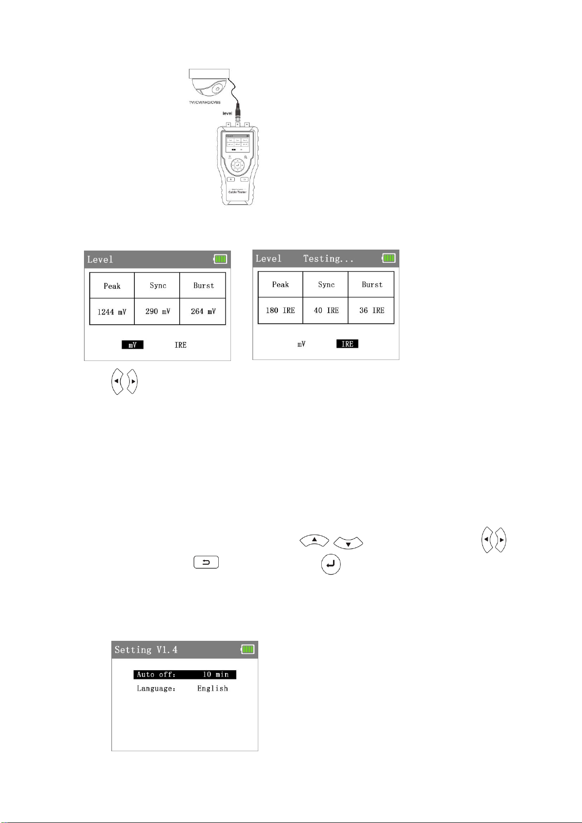
6. Video level meter test (Optional)
The Level value is an important indicator reflecting the signal quality and strength of the coaxial HD video image.
The meter detects the peak, sync and burst level of TVI, CVI, AHD, CVBS video signals in real time. Connect the
CVI/TVI/AHD/CVBS camera to tester’s “LEVEL” port.
Page 18
16
Press key to “level” icon and enter to app interface, the tester will auto start testing, the top of screen will display
“Testing”, and auto display the peak level, sync level and burst level.
Press key to switch the MV and IRE (Institute of Radio Engineers) mode, NTSC format uses IRE as the
unit of measurement, and PAL format uses mV as the unit of measurement.
If the cable too long, it will cause the video signal attenuation, the image will be dim and reduce the dynamic range
of the image. If the video signal is too strong, it will cause ghost images and reduce the resolution of the image.
7. Other functions
7.1 Setting
Press key to “Setting” icon and enter to app interface, press key to select the function. Press
key to adjust the value, press key to save and exit, press key to cancel and exit the setting.
Auto off: The meter can set 10-120 minutes auto power off, or close the auto power off function. If user not use
the tester in setting time, the meter will be turned off.
Language: Chinese and English
Page 19

17
7.2 PD powered detected
1236 pins supply power
4578 pins supply power
1236 and 4578 pins supply power
PoE switch or PSE power supply device connected to the “PD” port of the wire receiver, if the indicator light is on,
it means PoE voltage output working normal. There are 2 indicators lights of the “PD” port, when testing
the pins used of PoE switch for power supply, if 1236 indicator light is ON, it means PoE switch supply power
through Pin 1236. If 4578 indicator light is ON, it means PoE switch supply power through pins 4578. If 1236 and
4578 indicator lights are ON, it means device power supply through pins 1236 and 4578.
If the indicator light is lighting on, that is non-standard PoE. If the indicator light is flashing, that is standard PoE.
It also supports 24V and 48V PoE supply power device. The lamp brightness of 24V PoE is relatively dark, and the
lamp brightness of 48V PoE is relatively bright.
Application: Checking the pins used of PoE switch or other device for power supply, to avoid cause cannot supply
power or camera and other device damaged. Can detect the voltage of POE power supply device, PoE is standard
or non-standard.
7.3 Telephone status
Telephone status detection: If detected the telephone status, please turn off the cable tester. The RJ11 indicator
light flash is ringing, the indicator light on is standby, the indicator light off is off-hook.
Positive/negative polarity detection: Turn off the cable tester, the red and black alligator clip of RJ11 to clip the
cable. If the indicator light is red, that means the red wire clip is positive, and the black wire clip is negative. If the
indicator light is green, that means the black wire clip is positive, and the red wire clip is negative. The level higher,
the indicator light is brighter, if the level lower, the indicator light is darker.
Page 20

18
8. Specification
LCD
Item series
CTX1200
Display
2.4 inch TFT-LCD screen , 320x240 resolution
Cable test and
cable tracer
UTP cable
test
Test UTP cable's sequence, type and remote kit, quickly detect the near-end,
mid-end and far-end fault point of RJ45 cable connector
Cable type
RJ45 Twisted pair, RJ11 telephone line, BNC cable etc.
The fault of
RJ45 cable
connector
Can determine the fault point of RJ45 cable connector from
LOCAL/Remote indicator light
RJ45 TDR cable
test
Test cable pair status, length, attenuation, reflectivity, impedance, and skew etc.
measurement range 180M.
TDR cable test
Can test break point and short-circuit of cat 6e/5e (4 pairs), power line, BNC cable and
Telephone line, etc. the MAX. 1.2km length.(Optional)
Port flashing
Can search the Ethernet switch port which connect the meter
PING test
Check whether IP camera or other network equipment’s Ethernet port is working normally,
the IP address whether is correct.
IP Scan
Quickly find the IP address of the IP camera or other network equipment which connected to
the meter
Link Monitor
Quickly identify the connected network port (10/100/ 1000M) and duplex mode (full duplex
/ half duplex).
External power
supply
DC 5V/1A
Battery
Built-in 3.7V Lithium Ion battery, 2000mAh.
Rechargeable
After charging 3 hours, normal working time 16 hours
Auto off
1-30 (mins)
Working
Temperature
14 to 122°F (-10℃---+50℃)
Working
Humidity
30%-90%
Dimension/Weight
5.0” x 3.3” x 1.3” (126mm x 83mm x 33mm / 0.75lb (0.34kg)
Warranty
Triplett / Jewell Instruments extends the following warranty to the original purchaser of these goods for use. Triplett warrants to the
original purchaser for use that the products sold by it will be free from defects in workmanship and material for a period of (1) one year
from the date of purchase. This warranty does not apply to any of our products which have been repaired or altered by unauthorized
persons in any way or purchased from unauthorized distributors so as, in our sole judgment, to injure their stability or reliability, or which
have been subject to misuse, abuse, misapplication, negligence, accident or which have had the serial numbers altered, defaced, or
removed. Accessories, including batteries are not covered by this warranty
Copyright © 2021 Triplett
www.triplett.com
 Loading...