

Page 1

Model 9065
True RMS Data Logging MultiMeter
Instruction Manual
84-910
12/15
Page 2

Contents
I. Introduction----------------------------------------------------------1
II.Included Items------------------------------------------------------1
Ill. Rules for Safe Operation---------------------------------------2
IV. Electrical Symbols-----------------------------------------------3
V. Meter Structure----------------------------------------------------4
VI. LCD Display-------------------------------------------------------5
VII. Keys, Rotary Switch and Input Terminals-----------------6
VIII. Technical lndex--------------------------------------------------8
1. General Specications---------------------------------------8
2. Electrical Specications-------------------------------------9
IX. Measurement Operation--------------------------------------17
1. Meter Power Control----------------------------------------17
2. Meter Settings------------------------------------------------18
3. AC Voltage----------------------------------------------------20
4. DC Voltage----------------------------------------------------20
5. AC and DC Current-----------------------------------------21
6. Resistance----------------------------------------------------22
7. Conductance-------------------------------------------------24
8. Capacitance--------------------------------------------------24
9. Continuity------------------------------------------------------25
10. Diode Test----------------------------------------------------25
11. Frequency/Duty Cycle Measurement/Pulse Width-27
12. Temperature------------------------------------------------27
13. LPF-----------------------------------------------------------28
14. dBV-----------------------------------------------------------29
15. dBm----------------------------------------------------------29
16. Maximum Value and Minimum Value----------------29
17. Relative Value Mode-------------------------------------30
18. Peak Detection Mode------------------------------------30
19. Compare Mode--------------------------------------------30
20. Recording Measurement Data------------------------31
21. Communication-------------------------------------------33
X. Maintenance and Repair-------------------------------------34
1. General Maintenance and Repair---------------------34
2. Testing Fuses-----------------------------------------------34
3. Replacing Fuses-------------------------------------------35
4. Battery Charge---------------------------------------------35
X. Warranty-----------------------------------------------------------36
X. Notes---------------------------------------------------------------37
Page 3

I. Introduction
The Model 9065 is a 60000 count, or 4 5/6 digit,
handheld auto-ranging true RMS Digital Multimeter
(hereinafter referred to as “the meter’’). The meter can be
used to accurately measure AC and DC voltage, AC and
DC current, resistance, conductance, capacitance, temperature, frequency and pulse width. It can also perform
diode testing, continuity testing, and it provides useful test
functions such as data hold, maximum/minimum/average
measurements, comparison measurement, relative measurement, peak detection, trend capture and data record/
readback of as many as 20,000 measurements.
This Operating Manual provides information on safe and
recommended uses of this product. Please read the relevant information carefully and observe all the Warnings
and Notes.
Warning:
Please read the “Rules for Safe Operation” before using
the meter.
II. Included Items
Open the package and the carrying case and inspect the
contents. Please check that all of the following items are
included:
1. One operating manual
2. A pair of test leads
3. Two K type temperature probes
4. One temperature connector
5. One charging adapter
6. One charging connector
7. One USB cable
8. One CD
9. One cloth bag
If you discover any missing or damaged pieces, please
contact Triplett at 1-800 Triplett or support@triplett.com.
1
Page 4

III. Rules for Safe Operation
Please note the Warning symbol. Warnings indicate
the conditions and actions which pose hazards to users or
may damage the meter or equipment under test.
This Meter is designed to comply with several
safety standards, This meter conforms to UL STD. 61010-1,
61010-2-030, 61010-2-032, 61010-2-033, Certied to CSA
SID. C22.2 NO. 61010-1,61010-2-030, IEC STD 610102-032, 61010-2-033 in pollution degree 2, measurement
category (CAT III 1000V, CAT IV 600V), double insulation
as well as with IP65 standards for water resistance and
dustproong. Use of the meter without following the operating instructions can reduce or circumvent the protection
provided by the meter.
Measurement Category Ill (CAT Ill) is intended for
measurements performed in building installation. Examples
may include measurements on distribution boards, circuitbreakers, wiring, including cables, bus-bars, junction boxes,
switches, socket-outlets in xed installations, and equipment
for industrial use and some other equipment, for example,
stationary motors with permanent connection to the xed
installation.
Measurement Category IV (CAT IV) is intended for
measurements performed at the source of the low-voltage
installation. Examples include electricity meters and measurements on primary overcurrent protection devices and
ripple control units.
1. Never use a damaged meter. Before using the meter,
check the meter case for visible cracks or any missing plastic
parts. Pay special attention to the insulation areas around the
connectors.
2. Before using the meter, ensure the battery cover is closed
and secured. Before opening the battery cover, remove the
test leads from the meter.
3. Inspect the test leads for damaged insulation or exposed
metal. Check the test leads for continuity. If any test lead is
damaged, replace it before using the meter.
4. Do not apply more than the rated voltage, as marked on
the meter, between the terminals or between any terminal
and ground.
5. Do not have the meter turned on when removing the cover
or opening the case.
6. When working with a voltage >30V AC (RMS), >42VAC
(peak), or over 60V DC, special care should be taken to avoid
electric shock.
7. Replacement fuses must comply with the specications in
this Operating Manual.
8. Use the proper terminals, function and range for your measurement.
9. When measuring current, shut off the power to the circuit,
then connect the meter to the circuit. Remember: the meter
and the circuit must be connected in series.
10. When making electrical connections, connect the common test lead before connecting the main test lead; when
disconnecting, disconnect the main test lead before disconnecting the common test lead.
2
Page 5
11. If the meter works improperly, do not use it. The protection
measures of the meter may have failed. If in doubt, contact
your distributor or Triplett Customer Service.
12. Do not store or use the meter in an environment with high
temperature, humidity, strong magnetic elds, or with inammable or explosive materials.
13. When using the probes, keep your ngers behind the
nger guards.
14. Do not use the low-pass lter to verify hazardous voltage,
as there may be an AC voltage over the indicated value. First,
measure the voltage without a lter to check whether it is
hazardous, then select low-pass ltering.
15. Before testing resistance, continuity, conductance, diode
or capacitance, shut off the power to the circuit and discharge
all high-voltage capacitors.
17. Do not measure a voltage or current higher than the
allowed input values. When the range of measured values
cannot be determined, set the functional range switch at the
maximum-range position.
18. When the symbol shows on the LCD display, the
battery should be promptly charged to ensure measurement
accuracy.
19. Do not change the wiring within the meter to avoid injury
and damaging the meter.
20. A soft cloth and mild detergent should be used to clean
the surface of the meter when servicing. No abrasive cleaners or solvents should be used on the product.
21.Test a known voltage before use to conrm the meter is
functioning correctly.
22. If you want to replace the test lead, you need to replace
it with a test lead of the same or higher grade of CAT Ill
1000V/CAT IV 600V.
Dangerous Voltage
When the meter detects voltage ≥ 30V or overload (OL),
the symbol will display as a warning for potential hazardous voltage.
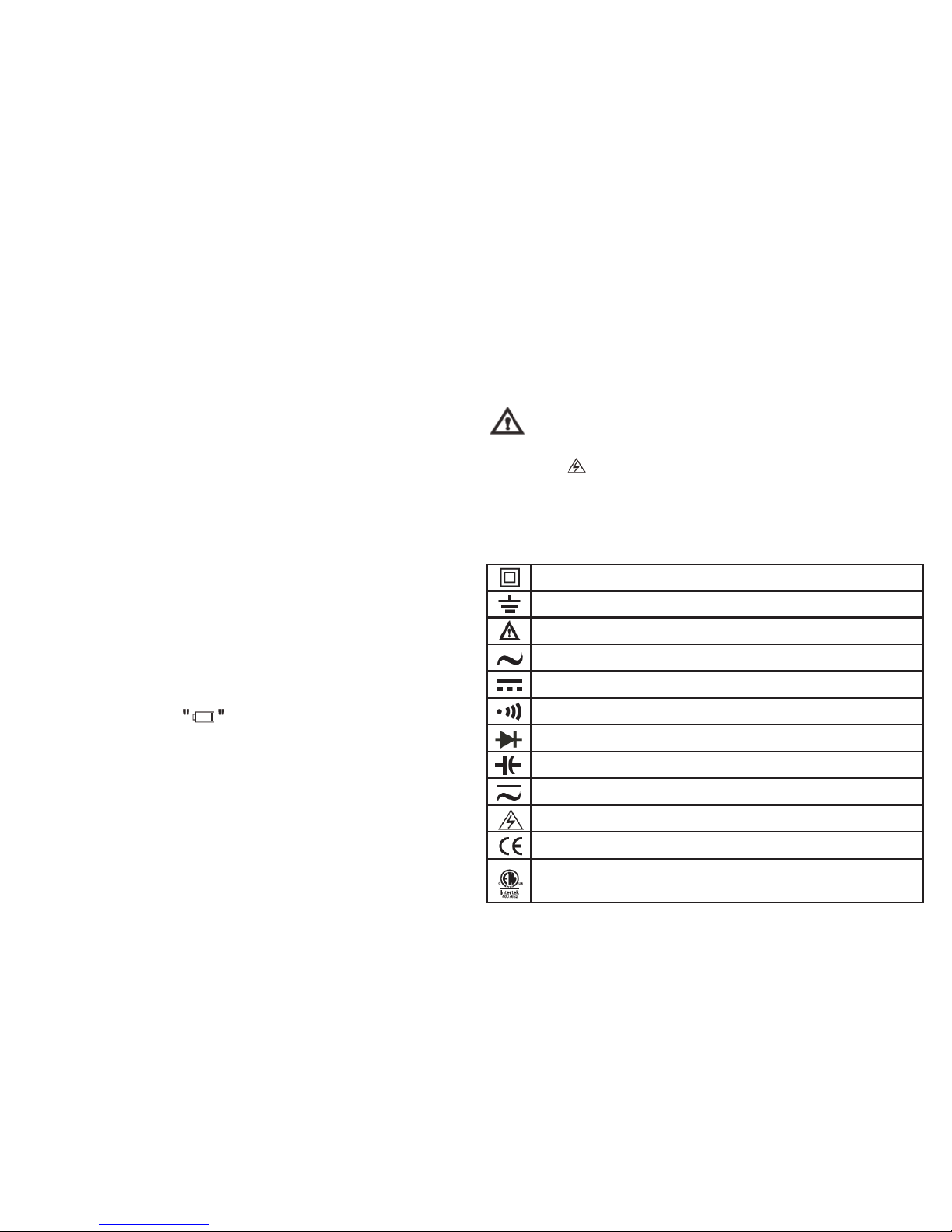
Double Insulated
Grounding
Warning
AC (Alternating Current)
DC (Direct Current)
Continuity Buzzer
Diode
Capacitance
AC or DC (Alternating Current or Direct Current)
Danger High Voltage
Conforms to Standards of European Union.
This symbol signies the product complies with both
USA and Canadian electrical requirements.
IV. Electrical Symbols
3
Page 6

V. Meter Structure (see Figure 1)
1
Case
2
LCD
3
Function Keys
4
Rotary Switch
5
Input Terminals
4
Page 7

V. LCD Display (see Figure 2)
No. Function Description
1
Label of Function
Keys
Indicates auxiliary functions under current
measuring interface
2
Simulation Bar Analog display of input signals
3
Minus Sign Indicates negative reading
4
Lightning Symbol Danger- High Voltage
5
Time and Date Indicates the time and date set in internal
clock
6
Small
Measurements
Real-time input values are displayed when
the primary and secondary displays are
covered by menus or pop-up messages.
7
Communications Indicates the USB communication is
enabled.
8
Sound Setting Indicates the button sound is enabled
(beeps when a button is pressed)
9
Battery Level Indicates the charge level of rechargeable
battery
10
Range Indicator Indicates the current range and range
mode for the meter (auto or manual)
11
Unit Indicates the measurement unit
12
Assisted Function
Mode
Indicates the active assisted measuring
function, such as Low Pass Filter
13
Assisted Function
Display
Shows additional measuring information
from the assisted function mode that is
active.
5
Page 8

VII. Keys, Rotary Switch and Input Terminals
(1) Keys
The 14 keys on the meter are used to activate the alternate functions of the rotary switch, browse menus or control the meter power.
The keys shown in Figure 3 are described in the following table.
Key Function
Turn on or turn off the power to the meter
F1 F2 F3 F4 Select the sub-functions and modes indicated by the labels on the LCD screen.
Cursor keys are used to select menu items, scroll through text and input data
HOLD Keep the current reading held on the display
RANGE Switch the range mode of the meter to Manual mode, then switch between all the available ranges. Long
press the button to return to Automatic range mode.
MAX MIN Starts to record Minimum & Maximum values.
SELECT Press to select the alternate function. Long press to enter Help Menu.
Press the key to switch the backlight brightness. Long press it to turn off backlight.
Knob Function
Measurement of AC Voltage
Measurement of mV in AC and mV in AC+DC
Measurement of voltage in DC and AC+DC
Measurement of mV in DC and temperature
Measurement of resistance, continuity and specic conductance
Diode test and capacitance measurement
(2) Rotary Switch (see Figure 4)
6
Page 9

Knob Function
Hz% mS-Pulse Measurement of frequency, duty cycle and pulse width
µA Measurement of A in AC, DC and AC+DC
mA Measurement of mA in AC, DC and AC+DC
A Measurement of ampere in AC, DC and AC+DC
Battery is charging
Terminal Description
A Measurement of frequency, duty cycle and pulse width
mA µA Measurement of A in AC, DC and AC+DC
COM Measurement of mA in AC, DC and AC+DC
VΩ °C Hz Measurement of ampere in AC, DC and AC+DC
(3) Input Terminals
In addition to the above, all four terminals are used for charging and temperature measurement through corresponding
adapters .”Lead Error!” will show on the display to warn if the probes are inserted improperly.
7
Figure 3 & 4
Page 10

VIII. Technical Index
1. General Specications
The maximum voltage between any terminal and ground: 1000 V
The fuse protection of mA or µA input terminals: 0. 8A H 1000V Fuse Type 6X32mm
The fuse protection of the A input terminal: 10A H1000V Fuse Type 10X38mm
Max. display: 60000
Range: Auto/Manual
Polarity: Auto
Operating temperature: -20°~50°C Storage temperature: -30°C~60°C
Relative humidity: ≤80% (0°C~30°C), ≤75% (30°C~40°C), ≤45% (40°C~50°C)
Electromagnetic compatibility: In an RF E-eld of 1V/m: Overall accuracy= specied accuracy+ 5% of range. No specied accuracy guarantee for RF E-eld strength > 1V/m.
Operating altitude: 0~2000m
Temperature coefcient: 0.1X (specied accuracy)/ °C (<18°C or >28°C) Internal battery: Lithium battery of 7.4V 2200mAh
Power adapter: Input of 100V~240V,50/60Hz 0.2A max, Output of DC10V 500mA(short-circuit protection for output). External
diameter of 5.5 mm and internal diameter of 2.5mm.
Low battery: The symbol shows on the LCD.
Dimension: About (225 X100 X 60) mm
Weight: About 608g (including battery)
Safety standards: IEC/EN61010-1, EN61010-2-030, EN 61010-2-033 in pollution degree 2, CAT III 1000V,CAT IV 600V IP65
standards for waterproof and dustrproof rating
8
Page 11

2. Electrical Specications
Accuracy: ±(% Reading + Digits), one-year calibration period.
Ambient temperature: 23°C± 5°C;
Ambient humidity: 75%RH;
Temperature coefcient: 0.1x (Accuracy)/ °C (<18 °C or >28°C)
2. Electrical Specications
Range Resolution Accuracy Tolerance: ± (% Reading + Digits)
60mV 0.001mV
45~1kHz 1k~10kHz 10k~20kHz 20k~100kHz
±(0.6%+60) ±(1.2%+60) ±(3%+60) ±(4%+60)
600mV 0.01V
45~1kHz 1k~10kHz 10k~20kHz 20k~100kHz
±(0.3%+30) ±(1.2%+40) ±(3%+40) ±(4%+40)
6V 0.0001V
45~1kHz 1k~10kHz 10k~20kHz 20k~100kHz
±(0.3%+30) ±(1.2%+40) ±(3%+40) ±(4%+40)
60V 0.001V
45~1kHz 1k~10kHz 10k~20kHz 20k~100kHz
±(0.3%+30) ±(1.2%+40) ±(3%+40) ±(4%+40)
600V 0.01V
45~1kHz 1k~10kHz 10k~20kHz 20k~100kHz
±(0.3%+30) ±(1.2%+40) ±(3%+40) Only for reference
1000V 0.1V
45~1kHz 1k~5kHz 5k~10kHz 10k~100kHz
±(0.6%+30) ±(3%+40) ±(6%+40) Only for reference
• Input impedance: About 10MΩ
• Overload protection: 1000V
• Display: True RMS value for 10% to 100% of the range.
9
Page 12

(2) DC Voltage
Range Resolution Accuracy Tolerance: ± (% Reading + Digits)
60mV 0.001mV ± (0.025%+20)
600mV 0.01mV
± (0.025%+5)6V 0.0001V
60V 0.001V
600V 0.01V
± (0.03%+5)
1000V 0.1V
(3) AC Voltage + DC Voltage
Range Resolution Accuracy Tolerance: ± (% Reading + Digits)
60mV 0.001mV
50~1kHz 1k~10kHz 10k~35kHz
+(1%+80) +(3%+40) +(6%+40)
600mV 0.01V
50~1kHz 1k~10kHz 10k~35kHz
+(1%+80) +(3%+40) +(6%+40)
6V 0.0001V
50~1kHz 1k~10kHz 10k~35kHz
+(1%+80) +(3%+40) +(6%+40)
60V 0.001V
50~1kHz 1k~10kHz 10k~35kHz
+(1%+80) +(3%+40) +(6%+40)
600V 0.01V
50~1kHz 1k~10kHz 10k~35kHz
+(1%+80) Only for reference Only for reference
1000V 0.1V
50~1kHz 1k~10kHz 10k~35kHz
+(1.2%+80) Only for reference Only for reference
• Input impedance: About 10MΩ
• Overload protection: 1000V
• Display: True RMS value for 10% to 100% of the range.
10
Page 13

• Input impedance: About 10MΩ
• Overload protection: 1000V
• Display: True RMS value for 10% to 100% of the range.
(4) AC Current
Range Resolution Accuracy Tolerance: ± (% Reading + Digits)
600µA 0.01µA
45~1kHz 1k~10kHz
+(0.6%+40) +(1.2%+40)
6000µA 0.1µA
45~1kHz 1k~10kHz
+(0.6%+20) +(1.2%+40)
60mA 0.001mA
45~1kHz 1k~10kHz
+(0.6%+40) +(1.2%+40)
600mA 0.01mA
45~1kHz 1k~10kHz
+(0.6%+20) +(1.2%+40)
10A 0.001A
45~1kHz 1k~10kHz
+(1%+20) +(3%+40)
• Display: True RMS value for 10% to 100% of the range.
• Overload protection: µAmA range: 0.8A H 1000V Fuse Type ɸ 6x32 mm
10 A range: 10A H 1000V Fuse Type ɸ 10x38mm
• Switch on for 30 seconds and suspend measurement for 10 minutes for 20A. Not specied for over 10A.
11
Page 14

(5) DC Current
Range Resolution Accuracy Tolerance: ± (% Reading + Digits)
600µA 0.01 µA +(0.08%+20)
6000µA 0.1 µA + (0.08%+10)
60mA 0.001 mA + (0.08%+20)
600mA 0.01 mA +(0.15%+10)
10A 0.001A +(0.5%+10)
• Overload protection: µAmA range: 0.8A H 1000V Fuse Type ɸ 6x32 mm
10 A range: 10A H 1000V Fuse Type ɸ 10x38mm
• Switch on for 30 seconds and suspend measurement for 10 minutes for 20A. Not specied for over 10A.
(6) AC Current + DC Current
Range Resolution Accuracy Tolerance: ± (% Reading + Digits)
600µA 0.01µA
50~1kHz 1k~10kHz
+(0.8%+40) +(2.0%+40)
6000µA 0.1µA
50~1kHz 1k~10kHz
+(0.8%+20) +(2.0%+40)
60mA 0.001mA
50~1kHz 1k~10kHz
+(0.8%+40) +(2.0%+40)
600mA 0.01mA
50~1kHz 1k~10kHz
+(0.8%+20) +(2.0%+40)
10A 0.001A
50~1kHz 1k~10kHz
+(1.2%+20) +(3%+40)
12
Page 15

• Display: True RMS value for 10% to 100% of the range.
• Overload protection: µAmA range: 0.8A H 1000V Fuse Type ɸ 6x32 mm
10 A range: 10A H 1000V Fuse Type ɸ 10x38mm
• Switch on for 30 seconds and suspend measurement for 10 minutes for 20A. Not specied for over 10A.
Range Resolution Accuracy Tolerance: ± (% Reading + Digits)
600Ω 0.01Ω In REL state: ±(0.05%+10)
6kΩ 0.0001kΩ
+(0.05%+2)60kΩ 0.001kΩ
600kΩ 0.01kΩ
6MΩ 0.0001MΩ +(0.3%+10)
60MΩ 0.001MΩ +(0.3%+10)
(7) Resistance
• Overload protection: 1000V
• Humidity for 60 MΩ: <50%
Range Resolution Accuracy Tolerance: ± (% Reading + Digits)
60ns 0.01nS +(2%+10)
(8) Conductance
• Overload protection: 1000V
• Humidity: <50%
13
Page 16

(9) Capacitance
Range Resolution Accuracy Tolerance: ± (% Reading + Digits)
6nF 0.001nF +(3%+10)
60nF 0.01nF +(2.5%+5)
600nF 0.1nF
+(2%+5)
6µF 0.001µF
60µF 0.01µF
600µF 0.1µF
6mF 1µF +(5%+5)
60mF 10µF Not specied
• Overload protection: 1000V
• Display digits: 6000
(10) Temperature
Range Resolution Accuracy
-40°C~40°C
0.1°C
+(2.0%+30)
40°C~400°C +(1.0%+30)
400°C ~1000°C +2.5%
-40°F~104°F
0.2°F
±(2.5%+50)
104°F~752°F +(1.5%+50)
752°F~1832°F +2.5%
Overload protection: 1000V
• Two-channel temperature measurement can be performed via temperature connectors.
• Temperature sensor: Applicable to K type(chromel-silicel) thermocouple. Spare parts are point contact
Ktype (chromel-silicel) thermocouple (only applicable to the measurement when temperature is below 800°C)
14
Page 17

(11) Frequency
Range Resolution Accuracy
60Hz 0.001 Hz +(0.02%+8)
600Hz 0.01 Hz
+(0.01%+5)
6kHz 0.0001kHz
60kHz 0.001kHz
600kHz 0.01kHz
6MHz 0.0001MHz
60MHz 0.001MHz
• Overload protection: 1000V
• Display digits: 6000
Range Resolution Accuracy Tolerance: ± (% Reading + Digits)
10%~90%(10Hz~2kHz) 0.01% +(1.2%+30)
(12) Duty Cycle
• Overload protection: 1000V
• Humidity: <50%
Range Resolution Accuracy Tolerance: ± (% Reading + Digits)
250mS 0.001mS~0.01mS +(1.2%+30)
(13) Pulse Width
• Overload protection: 1000V
• When the rise time is less than 1 µs, the signals center on trigger level.
• The pulse width is greater than 2 µs for 10Hz to 200kHz. The pulse width depends on signal frequency.
15
Page 18

Range Resolution Remark
0.01Ω
Open circuit voltage is around 3V.
When the buzzer is set for Short Circuit warning; If the impedance tested is
less than 10Ω, the buzzer continuously sounds. If the impedance tested is
greater than 50Ω, the buzzer does not sound.
When the buzzer is set for Open Circuit warning; If the impedance tested is
greater than 50Ω, the buzzer continuously sounds. If the impedance tested is
less than 10Ω, the buzzer does not sound.
(14) Continuity Test
• Overload protection: 1000V
Range Resolution Remark
0.0001V
Open circuit voltage is around 3V. The forward voltage drop value of the mea-
sured PN junction is approximately ≤ 3V.
When the buzzer is selected in Diode Test Mode; it will beep briefly for the
normal semiconductor junction. If the semiconductor junction shorts out (im-
pedance <10Ω), the alarm will continuously sound. Typical silicon PN junction
voltage drops vary between 0.5~0.8V.
(15) Diode Test
• Overload protection: 1000V
16
Page 19

IX. Measurement Operation
1. Meter Power Control
1) To manually power up and power down the meter:
When the meter is off, long press to start the meter. When the meter is on, long press to shut it off.
The meter cannot be powered off when charging.
2) Indicators for Battery Level:
The meter is powered by a rechargeable lithium battery. The indicators for battery level are in the upper right corner of the
When the battery capacity is lower than 3% of full capacity, the meter will automatically shut down.
3) Backlight Control
If the display is not visible in low-light situations, press the backlight button to switch the backlight brightness. Long
press the button to turn off the backlight and enter power saving mode. When the backlight is off, the green light
ashes to indicate that the meter is still collecting data. Press any key or turn the rotary switch to turn on the backlight again.
4) Auto Power-off
When the Auto Power Off is set, the meter will turn off if no button is pressed or the dial selector is not turned within the time
set. To disable Auto Power Off, set the Power Off mode to “OFF” under the SETUP – Auto Power Save Menu.
5) Power Saving Mode
Set the control time for dimming the brightness and turning off the display, found in the SETUP – Auto Power Save Menu
17
Page 20

2. Meter Settings
Press the function key labelled, SETUP to access the general settings for the meter. Press the cursor keys to
navigate through the settings menu.
1) Keypad Tone
This function enables or disables sound when a button is pressed. The beeper symbol in the upper right corner
indicates that sound is enabled.
2) Lead Alarm Buzzer
This function enables or disables the alarm sound for improper probe lead connection.
3) Communication
Set as ON to enable USB communication. A symbol will appear in the upper right corner when active. When
Communication Mode is OFF, the symbol will disappear.
4) Date & Time
With “Date & Time” highlighted in the SETUP Menu, press the function key labelled, “SET” to set the date and time.
Press (LEFT) or (RIGHT) to select the eld to edit, and press (UP) or (DOWN) to enter different numbers, then press the
function key “OK” to conrm. To cancel the settings, press the function key labelled, “CANCEL”.
5) Auto Power Save Options
With “Auto Power Save” highlighted in the SETUP Menu, press the function key labelled, “SET” to edit the time of inactivity
to dim the brightness, turn off the display, and power down the meter. Press (UP) or (DOWN) to move the cursors to select
different items. Press (LEFT) or (RIGHT) to enter the time, in minutes, to activate the power saving feature.
Menu Item Description Set Value
Brightness Down
Dim the display brightness after the elapsed
time of inactivity.
ON: 1-60 Min OFF: This function is disabled
Display Off Turn off the display after the elapsed time. ON: 1-60 Min OFF: This function is disabled
Power Off Turn off the power after the elapsed time. ON: 1-60 Min OFF: This function is disabled
Press the function key “OK” to conrm the above settings. To cancel the settings, press the function key “CANCEL”.
18
Page 21

6) More Settings
With “More Settings” highlighted in the SETUP Menu, press the function key “ENTER” to: Set the language of the Help
Menu, Format Memory, Reset the meter settings, or check the model number, serial number and available memory space.
Press the cursor keys to select between the following menu items.
- Help Menu Language
Press the function key labelled, “SET” to set the Help Menu language. Press (UP) or (DOWN) to select a different lan
guage. Then press the function key “OK” to conrm. To cancel the settings, press the function key “CANCEL”.
- Memory Format
With “Memory Format” highlighted, press the function key labelled, “FORMAT” to enter the memory format menu, then
press the function key labelled “YES” to conrm. To cancel the format, press the function key labelled, “NO”.
- Reset All Setting
With “Reset All Setting highlighted, Press the function key “RESET” to reset the meter to default settings, then press the
function key “YES” to conrm. To cancel the reset, press the function key “NO”.
- About
Press the function key “ABOUT” to check product model, serial number and available memory space.
19
Page 22

3. AC Voltage
1) Insert the red test lead into the V terminal and the black
test lead into the COM terminal.
2) Set the rotary switch to V or mV as shown in Figure 5.
Connect the test leads to the power or load under test in
parallel.
3) Directly read the measured voltage values on the display.
True virtual values are displayed for AC measurement.
4) Press the function key labelled, “MENU” to access
additional features for measuring AC voltage. Press
the cursor keys to select menu items. The red
highlighting indicates the selected item. Press F1
to enter the corresponding measuring mode, press F2 to
enter Relative value mode when available, and press F3
to set dBm impedance (AC V only), and press F4 to close
the measurement features menu.
Attention:
After completing all the measuring operations, disconnect the test leads and the circuit under test Do not input a
voltage higher than 1000V. Higher voltage may be
measured but it may damage the meter.
• When measuring high voltage, special care should be
taken to avoid electric shock.
• After completing all the measuring operations, disconnect
the connection between the test leads and the circuit under
test.
• The meter’s True RMS response is calibrated to an AC sinusoidal input signal. Measuring non-sinusoidal AC signals
will have decreased accuracy.
4. DC Voltage
1) Insert the red test lead into the V terminal and the black
test lead into the COM terminal.
2) Set the rotary switch to DC V or DC mV as shown in
Figure 6. Connect the test leads to the power
or load under test in parallel.
3) Directly read the measured voltage values on the display.
4) Press the function key labelled, “MENU” to access
additional features for measuring DC voltage. Press
the cursor keys to select menu items. The red
highlighting indicates the selected item. Press F1 to
enter the corresponding measuring mode, press F2 to
enter Relative value mode when available, and press F4
to close the measurement features menu.
20
Page 23

Attention:
• Do not input a voltage higher than 1000V. Higher voltage
may be measured but it may damage the meter.
• When measuring high voltage, special care should be
taken to avoid electric shock.
• After completing all the measuring operations, disconnect
the connection between the test leads and the circuit under
test.
5. AC and DC Current
1) Insert the red test lead into the µAmA or A terminal and
the black test lead into the COM terminal.
2) Set the rotary switch to the position as shown in Figure 7.
Press the key “SELECT” to measure either AC or DC.
Connect the test leads to the test circuit in series.
3) Directly read the measured current values on the display.
4) Press the function key labelled, “MENU” to access
additional features for measuring AC or DC current.
Press the cursor keys to select menu items.
The red highlighting indicates the selected item. Press F1
to enter the corresponding measuring mode, press F2 to
enter Relative value mode when available, and press F4
to close the measurement features menu.
Warning:
• Before connecting to the test circuit, turn off the power to
the circuit rst and discharge all the high-voltage
capacitors.
• Use proper input terminals and functions for measurement.
If the current amperage cannot be estimated, rst measure
using the largest range.
• When the test lead is inserted in a current terminal, do not
connect its test probe to any circuit in parallel, it could
blow the fuses within the meter and damage the meter.
• After completing all the measuring operations, disconnect
the connection between the test leads and the circuit under
test.
21
Page 24

22
Page 25

6. Resistance
1) Insert the red test lead into the Ω terminal and the black
test lead into the COM terminal.
2) Set the rotary switch to the Ω nS position. The
meter will default to resistance measurement. Connect
the test leads to both ends of the measured resistance as
shown in Figure 8.
3) Directly read the measured resistance values on the
display.
Attention:
• If measuring an open circuit or resistance value exceeds
the maximum range of the meter, “OL” will show on the
display.
• When measuring the in-circuit resistance, all the power
within the measured circuit must be shut off before
measurement and all the capacitors must be discharged to
ensure a correct measurement, and to avoid damaging the
meter.
• When measuring low resistance, the test leads may
add additional resistance between 0.10 Ω to 0.20Ω. To
obtain accurate readings, Relative measurement can be
used. First short the input test leads, then press the
function key labelled, “MENU” and press F2 to enter
Relative measurement mode. Perform the low resistance
measurement and the meter will automatically subtract the
resistance of the shorted test leads.
• If the resistance value is greater than 0. 50Ω with shorted
test leads, the test leads should be checked for loose
connections or other factors.
• When measuring a resistance >1MΩ, the readings require
a few seconds to stabilize. This is normal for high resis
tance measurements. In order to obtain stable readings,
short test lines can be used for the measurement.
• Do not input a voltage in resistance measurement mode to
avoid possible product damage or personal injury.
• After completing all the measuring operations, disconnect
the connection between the test leads and the circuit under
test
23
Page 26

7. Conductance
1) Insert the red test lead into the Ω terminal and the black
test lead into the COM terminal.
2) Set the rotary switch to the measurement Ω nS .
Press the SELECT key twice to select Conductance
measurement. Connect the test leads to both ends of the
measured resistance as shown in Figure 8.
3) Directly read the measured conductance value on the
display.
Attention:
• When measuring the in-circuit resistance, all the power
within the measured circuit must be shut off before
measurement and all the capacitors must be discharged to
ensure a correct measurement, and to avoid damaging the
meter.
• Do not input a voltage when in conductance measurement
mode to avoid possible product damage or personal injury.
• After completing all the measuring operations, disconnect
the connection between the test leads and the circuit under
test.
8. Capacitance
1) Insert the red test lead into the terminal and the
black test lead into the COM terminal.
2) Set the rotary switch to the measurement
press the SELECT key to select Capacitance
measurement. Connect the test leads to both ends of the
measured capacitance as shown in Figure 9.
3) Directly read the measured capacitance value on the
display.
Attention:
• If the measured capacitance shorts or capacitance value
exceeds the maximum range of the meter, “OL” will show
on the display.
• For the measurement of small capacitance within range,
relative measurement REL should be used to avoid the
inuence of test lead capacitance for correct readings.
• For capacitance measurements > 600 µF,
the readings require a few seconds to be stable.
• To ensure the measuring accuracy, the capacitor should
be discharged completely then put onto the meter to
measure, especially for a capacitor with high voltage to
avoid damage to the meter and personal injury.
• Do not input a voltage when in capacitance measurement
mode to avoid possible product damage or personal injury.
• After completing all the measuring operations, disconnect
the connection between the test leads and the capacitor
under test.
24
Page 27

9. Continuity Test
1) Insert the red test lead into the Ω terminal and the black
test lead into the COM terminal.
2) Set the rotary switch to the measurement Ω nS ,
press the SELECT key to select the Continuity test
. Connect the test leads to both ends of
the measured resistance as shown in Figure 8. Press
the function key labelled, “MENU” to select measurement
options. Pressing the function key labelled, “SHORT”
will put the meter in Short Circuit Alarm mode. Pressing
the function key labelled, “OPEN” will put the meter in
Open Circuit Alarm mode.
When the buzzer is set for Short Circuit warning; If the
impedance tested is less than 10Ω, the buzzer continuously
sounds. If the impedance tested is greater than 50Ω, the
buzzer does not sound.
When the buzzer is set for Open Circuit warning; If the
impedance tested is greater than 50Ω, the buzzer continuously sounds. If the impedance tested is less than 10Ω, the
buzzer does not sound.
3) Directly read the measured resistance value on the
display.
Warning
• When measuring the in-circuit resistance, all the power
within the measured circuit must be shut off before
measurement and all the capacitors must be discharged to
ensure a correct measurement.
• Do not input a voltage when in continuity test mode to
avoid possible product damage or personal injury.
• After completing all the measurements, disconnect the
connection between the test leads and the circuit under
test.
10. Diode
1) Insert the red test lead into the terminal and the
black test lead into the COM terminal. The polarity of red
test lead is “+” and “-” for black test lead.
25
Page 28

2) Set the rotary switch to the position.
The meter will default to Diode measurement. Connect
the test leads to both ends of the diode as shown in
Figure 10. Directly read the approximate forward
PN junction voltage of the measured diode on the
display.
3) Press the function key labelled, “MENU” to choose
measurement options. Pressing the function key
labelled,“ALARM” will enable the beeper. It will beep
briey when connected to a normal semiconductor
junction; If the measurement shorts out, it will beep
continuously. Typical Silicon PN junction drops vary
between 0.5V ~ 0.8V. Pressing the function key labelled,
“NORMAL” will run the diode test without the beeper
function.
Attention:
• If the measurement is an open circuit, or the diode polarity
is reversed, “OL” will be displayed.
• When measuring an in-circuit diode, all the power within
the measured circuit must be shut off before measurement
and all the capacitors must be discharged.
• Open-circuit voltage of diode test is around 3V.
• Do not input a voltage when in diode test mode to avoid
possible product damage or personal injury.
• After completing all measurements, disconnect the
connection between the test leads and the circuit under
test.
26
Page 29

11. Frequency/Duty Cycle Measurement /Pulse
Width
1) Insert the red test lead into the V terminal and the black
test lead into the COM terminal.
2) Set the rotary switch to the measurement Hz%
ms-Pulse position. Press the SELECT key to select Hz,
Duty Cycle (%), or ms-Pulse. Connect the test leads to
the signal source under test in parallel as shown in
Figure 11.
3) Directly read the measured values of frequency, duty
cycle or pulse width on the display.
Attention:
• Simulation bar displays the frequency of the measured
signal for duty cycle and pulse width.
• After completing all measurements, disconnect the
connection between the test leads and the circuit
under test.
12. Temperature
1) Set the rotary switch to the measurement mV °C °F then
press the SELECT key to choose Celsius °C or
Fahrenheit °F. Insert the temperature connector into the
four input terminals and connect two temperature probes
to the temperature connector as shown in Figure 12. The
temperature probes detect the surface temperature of the
object under test.
2) Directly read the temperature values of the two sensors
on the display.
3) Press the function key labelled, “MENU” to choose
measurement options. Scroll through the menu with
keys and press F1 to choose the highlighted
option. Press F2 while in the Menu to enter Relative
Mode. Press F4 to close the Menu.
27
Page 30

Attention:
• If the ambient temperature for the meter is outside the
range of 18 °C to 28 °C, it may cause measurement errors.
The measurement effects are more obvious at low
temperatures.
• Remove the temperature probes after completing all the
measurements.
• Point contact K type (chromel-silicel) thermocouple
accuracy specication is for temperature measurements
below 230 °C.
13. LPF Measurement
1) Insert the red test lead into the V terminal and the black
test lead into the COM terminal.
2) Set the rotary switch to v. Connect the test leads to the
power or load to be tested in parallel as shown in
Figure 5.
3) Press the function key labelled, “MENU” to choose
measurement options. Press the cursor keys
to highlight “Low Pass”, then press the function key
labelled, “Low Pass” to enter LPF measuring mode.
4) The meter performs the measurement in AC mode.
The AC signals go through a lter which lters out
voltage signals with frequencies higher than 1KHz. As
shown in the following gure, the low-pass lter can
measure the composite signals of sinusoidal waves
generated by inverter and variable-frequency motor.
Attention:
• To avoid electric shock or personal injury, do not use the
low-pass lter to verify hazardous voltage, there may be
a voltage over the indicated value. First, measure the
voltage without a lter to check whether it is hazardous,
then select low-pass ltering.
28
Page 31

• In the LPF measuring mode, the meter will turn to manual
mode. Press the RANGE key to select a range. When the
low-pass lter is enabled, automatic range is unavailable.
• Do not input a voltage above 1000V. Higher voltage may
be measured but it poses the risk of damaging the meter.
• After completing all measurements, disconnect the
connection between the test leads and the circuit under
test.
14. dBV
1) Insert the red test lead into the V terminal and the black
test lead into the COM terminal.
2) Set the rotary switch to v. Connect the test leads to the
power or load to be tested in parallel as shown in
Figure 5.
3) Press the function key labelled, “MENU” to choose
measuring options. Press the cursor keys to
highlight “dBV”, then press the function key labelled,
“dBV” to enter dBV measurement mode.
4) dBV is the primary measurement shown and AC voltage
value is the secondary value shown on the display. AC
voltage of the measured signal is also displayed on the
15. dBm
1) Insert the red test lead into the V terminal and the black
test lead into the COM terminal.
2) Set the rotary switch to V. Connect the test leads to the
power or load to be tested in parallel as shown in
Figure 5.
3) Press the function key labelled, “MENU” to choose
measurement options. Press the cursor keys
to highlight “dBm”. A reference impedance must be
used to calculate the dBm measurement. Press the
function key labelled, “RES” to select a reference
impedance value. Press (UP) or (DOWN) to scroll
between ten dened reference values: 4, 8, 16, 25, 32,
50, 75, 600, 1000Ω, and User Dened. While selecting
a User dened reference impedance, press the function
key labelled, “EDIT” and use the cursor keys to
input a reference impedance value between
4-1,200Ω. Press the function key labelled, “OK” to set
reference values. Press the function key labelled, “dBm”
to enter dBm measurement.
4) dBm is the primary measurement shown and AC voltage
value is the secondary value shown on the display. AC
voltage of the measured signal is also displayed on the
simulation bar.
16. Maximum and Minimum Value
Press the “MAX MIN” key to activate Max Min Mode.
Real-time measurements are the primary value displayed.
Maximum, minimum, and average values, as well as
elapsed time, start date and times corresponding to the
three values are secondarily displayed.
29
Page 32

Press the function key labelled, “EXIT” to exit Max Min Mode.
17. Relative Value Mode
Press the function key labelled, “MENU” to enter the
measurement option menu. While in the menu, press the
function key labelled, “REL” to enter Relative Value Mode*.
The meter will store the value shown at the time that “REL” is
pressed as the “Reference” measurement. Press the
function key labelled, “REL” to store the present value as the
“Reference”. The real-time measurement will be displayed as
“Measurement”. The primary value displayed will be the Relative value (Measurement – Reference). Press the “MENU”
function key to select other modes and exit Relative Value
Mode. *NOTE: When applicable. Relative Value Mode is not
available for all measurement types.
18. Peak Detection Mode
While in a Voltage or Current measuring mode, press the
“MENU” function key to choose measurement options. While
in the menu, press the function key labelled, “PEAK” to activate Peak Detection Mode. Response time is 1ms. Transient
values can be more accurately measured by using Peak
Mode while using the Record function.
19. Compare Mode
Press the F3 function key labelled, “COMP” to begin Compare Mode. Press (UP) or (DOWN) to scroll between the
settings of Compare Mode. Press the “EDIT” function key to
edit the highlighted Compare Mode setting.
1) Pass Mode
• INNER(Low Value ≤ Input Value ≤ High Value)
• OUTER (Input Value < Low Value OR Input Value >High
Value)
• <Value
• >Value
Press the “OK” function key to conrm the above settings.
To cancel the settings, press the “CANCEL” function key.
2) Beep Mode
While highlighting the “Beep Mode” setting, press the “EDIT”
function key to edit the Beep settings. Press the keys
to select one of the three following options:
• PASS ON
The meter will beep when the Pass Mode criteria are met,
and the meter displays, “PASS”.
• FAIL ON
The meter will beep when the Pass Mode criteria are NOT
met, and the meter displays, “FAIL”.
• OFF
The meter will not beep in Compare Mode.
Press the function key OK to conrm the above
settings. To cancel the settings, press the “CANCEL”
function key.
3) Low Value or High Value or Value
This setting controls the value(s) for the Pass Mode criteria.
After completing the settings, press the “START” function
key to start the measurement in Compare Mode. Press the
“EXIT” function key to exit Compare Mode.
30
Page 33

20. Recording Measurement Data
Press the function key labelled, “SAVE” to enter the menu
for saving, recording or viewing data. Press the cursor keys
to select the following options.
1) Save
While in the Save menu, press the “SAVE” function key to
store the measurement currently displayed. Up to 20,000
measurements can be saved on the meter.
2) View Save
In the Save menu with “View Save” highlighted, press the
“VIEW” function key to view stored save les. Press or
hold the function keys labelled, “PREV” or “NEXT” to scroll
through the saved data. Press the “DELETE” function key to
delete the selected saved data. Press the “RETURN” function key to return to the last menu. In addition to displaying
the saved data, the le save # and total number of saved
les are displayed in the lower left corner. The date and time
of the saved data are displayed in the lower right corner.
3) Delete All Save
In the Save menu with “Delete All Save” highlighted, press
the function key labelled, “DELETE” to delete all saved data
les. Press the function key labelled, “YES” to conrm. To
cancel the operation, press the function key labelled, “NO”.
4) Record
In the Save menu with “Record” highlighted, press the function key labelled, “ENTER” to enter the continuous
recording mode with a maximum of 10000 data points.
Press (UP) or (DOWN) to edit the three following settings.
• Edit Name
In the Record Menu with “Edit Name” highlighted, press the
“EDIT” function key to edit the name of the recording. Press
(LEFT) or (RIGHT) to move the cursor and select where
to edit. Press the F1 key to switch the input to Uppercase
mode, then press (UP) or (DOWN) to input uppercase
letters. Press the F2 key to switch the input to Lowercase
mode, then press (UP) or (DOWN) to input lowercase letters. Press the F3 key to switch the input to Digit mode, then
press (UP) or (DOWN) to enter numbers or symbols. Press
the F4 key to save the Record name and exit edit mode.
• Set Interval
With “Set Interval” highlighted, press the “EDIT” function key
to set the time interval between recorded data points. Press
or hold (LEFT) or (RIGHT) to move the cursors to select
where to edit. Press or hold (UP) or (DOWN) to enter different numbers. The interval time can be set from 1 sec to 60
min between data points.
• Set Duration
With “Set Duration” highlighted, press the “EDIT” function key to set the duration of the recording. Press or hold
(LEFT) or (RIGHT) to move the cursors to select where
to edit. Press or hold (UP) or (DOWN) to enter different
numbers. The duration time can be set in days, hours and
minutes.
• Max Duration
Displays the maximum time for continuous recording with
the current settings. When ready to Record, press the
“START” function key to start a recording with the current
settings.
31
Page 34

When Recording, the characters “REC” show on the display
with a ashing red dot, as shown in Figure 13. The relevant
display information is shown in the following table.
To manually stop recording, press the “STOP” function
key. After stopping the recording, the record data will be
displayed. See the viewing options in the following “view
Record” section.
5) View Record
In the Save Menu with “View Record” highlighted, press the
“View” function key to view the information on recordings.
The data will be displayed as shown in Figure 14. The basic
display information is in the following table.
Information Description
Name Name of recording
Interval Time between data points
Duration Duration of recording from start to stop
Samples Total number of data points recorded
Maximum Maximum recorded value
Average Average value of the recorded data
Minimum Minimum recorded value
REC Record le number and total number of
recordings
Start Time and date at beginning of recording
Information Description
Elapsed Time Run time displayed in hours: minutes
Remaining
Time
Time left displayed in hours: minutes:
seconds
Samples Total number of recorded data points for
the active recording
Start Time and date of the start of the
recording.
32
Page 35

While viewing a Record, press the “PREV” function key to
display the previous record. Press the “NEXT” function key
to display the next record. Press the “RETURN” function key
to return to the previous menu. Press the function key labelled, “TREND” to view the recording graphically, as shown
in Figure 15. The display information of trend data is in the
following table:
No. Description
1 Measured value corresponding to cursor
2 Date and time of measurement at the cursor
3 Cursor
4 Trend line
5 Elapsed time labels on X-axis
6 Name of recording
7 Time and date at the start of the recording.
Viewing the trend chart: Press or hold the F2 key to move
the cursor left. Press or hold the F3 key to move the cursor right. The cursor moves one data point for each press.
Holding, or long pressing the keys will scroll through data
points more quickly. Press (UP) or (DOWN) to scale the
graph vertically. Press (LEFT) or (RIGHT) to scale the graph
horizontally.
Press the F1 key to delete this record. Press the function
key labelled, “YES” to conrm the deletion. To cancel the
deletion, press the “NO” function key.
6) Delete All Record
In the Save menu with “Delete All Record” highlighted, press
the function key labelled, “DELETE” to delete all record-
ings. Press the “YES” function key to conrm. To cancel the
operation, press the “NO” function key.
21. Communication
33
Page 36

USB Communication
Turn on communication via settings (see detailed operations
in the section 2. Meter Settings). The symbol will
appear in the upper right corner on the display as shown in
Figure 15.
The meter performs USB communication with the supplied
USB cable (standard accessory) connecting to the PC.
X. Maintenance and Repair
1. General Maintenance and Repair
Regularly clean the meter case with damp cloth and mild detergent. Do not use abrasives, isopropyl alcohol or solvents.
Dirt or moisture on the terminals can affect readings but can
also enable the “Lead Error” warning. Clean the terminals
according to the following steps:
1) Turn off the meter and remove all test leads.
2) Clean up the dirt on the terminals.
3) Soak a clean cotton swab in mild detergent and water.
Clean each terminal with the cotton swab. Dry each terminal
with canned compressed air to force water and detergent to
ow out of the terminals.
4) In the case of abnormal meter function, stop using it and
send it for repair.
5) When the meter needs to be veried or repaired, qualied
service personnel or a designated maintenance department
are required to repair it.
2. Testing Fuses
As shown in Figure 17, put the meter in resistance mode.
Insert a test lead into the terminal as shown in Figure 17
and contact the probe tip of the test lead with the metal in
the of a current input terminal. If the message, “Lead Error!”
(connection error for test leads) appears, it shows that the
probe tip is inserted too deeply in the input current terminal.
Draw out the test lead a little until the error message disappears and OL (overload) or resistance reading appears on
the display. If the resistance reading for A terminal is less
than 0.50Ω, it shows that the fuse F2 is normal. If the
reading is “OL”, you need to replace F2; If the resistance
reading of the µAmA terminal is less than 1.2MΩ, it shows
that the fuse F1 is normal. If the reading is OL, F1 needs to
be replaced;
34
Page 37

3. Replacing Fuses
Inspect or replace the meter fuse as shown in Figure 18
according to the following steps:
1) Turn off the meter and remove the test leads from the
terminals.
2) Use a at-head screwdriver to turn the screw on the bat-
tery cover counterclockwise, then remove the battery cover.
3) Gently pry one end of the fuse and then remove the fuse
from the clip.
4) The required fuse installed for mA or µA input terminal:
0.8A H 1000V Fuse Type 6X32mm (F1) The required fuse
installed for A input terminal: 10A H 1000V Fuse Type
10X38 mm (F2)
5) Reinstall the battery cover and then turn the screw
clockwise to tighten the battery cover.
4. Battery Charge
When the indicator of battery level in upper right corner is
less than 5% of full capacity, the meter should be immediately charged, otherwise it will affect the measurement
accuracy. As shown in Figure 19, set the rotary switch to
. The message, “Please plug in AC adapter!” will prompt
you to insert a power adapter for charging. Connect the
power connector to the four terminals in the meter, then
insert the power adapter into the power connector, as shown
in Figure 19. The message, “Charging” on the display indicates it is in charging with a progress bar displaying battery
charge to the nearest 5%. The power button will light red.
When the battery is fully charged, the red light will turn off
and the charging process stops. A “Charge
complete” message will display when fully charged.
Attention:
You must use the power adapter specied by Triplett.
35
Page 38

XI. Warranty
Triplett extends the following warranty to the original
purchaser of these goods for use. Triplett warrants to the
original purchaser for use that the products sold by it will be
free from defects in workmanship and material for a period
of (3) three years from the date of purchase.
This warranty does not apply to any of our products which
have been repaired or altered by unauthorized persons in
any way or purchased from unauthorized distributors so as,
in our sole judgment, to injure their stability or reliability, or
which have been subject to misuse, abuse, misapplication,
negligence, accident or which have had the serial numbers
altered, defaced, or removed. Accessories, including batteries and fuses, are not covered by this warranty.
To register a claim under the provisions of this warranty,
please contact the distributor from which you purchased the
product from for warranty
consideration.
ALL WARRANTIES IMPLIED BY LAW ARE HEREBY
LIMITED TO A PERIOD OF THREE YEARS FROM DATE
OF PURCHASE, AND THE PROVISIONS OF THE WARRANTY ARE EXPRESSLY IN LIEU OF ANY OTHER WARRANTIES EXPRESSED OR IMPLIED.
The purchaser agrees to assume all liability for any damages and bodily injury which may result from the use or misuse
of the product by the purchaser, his employees, or others,
and the remedies provided for in this warranty are expressly
in lieu of any other liability Triplett may have, including incidental or consequential damages.
Some states (USA ONLY) do not allow the exclusion or
limitation of incidental or consequential damages, so the
above limitation or exclusion may not apply to you No representative of Triplett or any other person is authorized to
extend the liability of Triplett in connection with the sale of its
products beyond the terms hereof.
Triplett reserves the right to discontinue models at any time,
or change specications, price or design, without notice and
without incurring any obligation.
This warranty gives you specic legal rights, and you may
have other rights which vary from state to state.
36
Page 39

XII. Notes
37
Page 40

Model 9065
Part Number: 9065
Made in China
84-910
10/15
 Loading...