

Page 1

CCAARR SSEECCUURRIITTYY AANNDD RREEMMOOTTEE SSTTAARRTT
IINNSSTTAALLLLAATTIIOONN GGUUIIDDE
E
1988-2004 Ford F-Series Pickups
Copyrght 2002-2004 Triple S Customs
Page 2

CAR ALARM AND REMOTE START INSTALLATION GUIDE
WIRING INFORMATION 1988 Ford F-Series
WIRE WIRE COLOR LOCATION
12V CONSTANT WIRE YELLOW Ignition Harness
12V IGNITION WIRE RED/LT.GREEN Ignition Harness
12V ACCESSORY WIRE GRAY/YELLOW Ignition Harness
STARTER WIRE RED/LT.BLUE Ignition Harness
PARKING LIGHTS (+) BROWN At Headlight Switch
POWER DOOR LOCK (5-wire
reverse polarity, test using
BLACK/ORANGE At Harness In Passenger Kick
Panel
driver’s door lock switch)
POWER DOOR UNLOCK (5-wire
reverse polarity, test using
PINK/GREEN At Harness In Passenger Kick
Panel
driver’s door lock switch)
DOOR TRIGGER/DOMELIGHT
BLACK/LT.BLUE At Courtesy Light Under Dash
SUPERVISION (+)
BRAKE WIRE (+) LT.GREEN Harness In Driver’s Kick Panel Or
Brake Pedal Switch
TACHOMETER WIRE TAN/YELLOW
WHITE/BLACK (Diesels)
At Ignition Coil
At Alternator
DIESEL WAIT-TO-START (-) BLACK/PINK Behind Instrument Cluster
HORN TRIGGER (-) DARK BLUE Harness At Steering Column
LEFT FRONT WINDOW UP RED At Driver Window Motor Inside
Door
LEFT FRONT WINDOW DOWN YELLOW At Driver Window Motor Inside
Door
RIGHT FRONT WINDOW UP RED/BLACK Harness In Driver’s Kick From
Driver Door
RIGHT FRONT WINDOW DOWN YELLOW/BLACK Harness In Driver’s Kick From
Driver Door
Copyrght 2002-2004 Triple S Customs 2
Page 3
CAR ALARM AND REMOTE START INSTALLATION GUIDE
WIRING INFORMATION 1989 Ford F-Series
WIRE WIRE COLOR LOCATION
12V CONSTANT WIRE YELLOW Ignition Harness
12V IGNITION WIRE RED/LT.GREEN Ignition Harness
12V ACCESSORY WIRE GRAY/YELLOW Ignition Harness
STARTER WIRE RED/LT.BLUE Ignition Harness
PARKING LIGHTS (+) BROWN At Headlight Switch
POWER DOOR LOCK (5-wire) BLACK/ORANGE At Harness In Passenger Kick
Panel
POWER DOOR UNLOCK (5-wire) PINK/GREEN At Harness In Passenger Kick
Panel
Test door lock wires using driver’s lock switch.
DOOR TRIGGER/DOMELIGHT
BLACK/LT.BLUE At Courtesy Light Under Dash
SUPERVISION (+)
BRAKE WIRE (+) LT.GREEN Harness In Driver’s Kick Panel Or
Brake Pedal Switch
TACHOMETER WIRE TAN/YELLOW
WHITE/BLACK (Diesels)
At Ignition Coil
At Alternator
DIESEL WAIT-TO-START (-) BLACK/PINK Behind Instrument Cluster
HORN TRIGGER (-) DARK BLUE Harness At Steering Column
LEFT FRONT WINDOW UP RED At Driver Window Motor Inside
Door
LEFT FRONT WINDOW DOWN YELLOW At Driver Window Motor Inside
Door
RIGHT FRONT WINDOW UP RED/BLACK Harness In Driver’s Kick From
Driver Door
RIGHT FRONT WINDOW DOWN YELLOW/BLACK Harness In Driver’s Kick From
Driver Door
Copyrght 2002-2004 Triple S Customs 3
Page 4
CAR ALARM AND REMOTE START INSTALLATION GUIDE
WIRING INFORMATION 1990 Ford F-Series
WIRE WIRE COLOR LOCATION
12V CONSTANT WIRE YELLOW Ignition Harness
12V IGNITION WIRE RED/LT.GREEN Ignition Harness
12V ACCESSORY WIRE GRAY/YELLOW Ignition Harness
STARTER WIRE RED/LT.BLUE Ignition Harness
PARKING LIGHTS (+) BROWN At Headlight Switch
POWER DOOR LOCK (5-wire) BLACK/ORANGE At Harness In Passenger Kick
Panel
POWER DOOR UNLOCK (5-wire) PINK/GREEN At Harness In Passenger Kick
Panel
Test door lock wires using driver’s lock switch.
DOOR TRIGGER/DOMELIGHT
BLACK/LT.BLUE At Courtesy Light Under Dash
SUPERVISION (+)
BRAKE WIRE (+) LT.GREEN Harness In Driver’s Kick Panel Or
Brake Pedal Switch
TACHOMETER WIRE TAN/YELLOW
WHITE/BLACK (Diesels)
At Ignition Coil
At Alternator
DIESEL WAIT-TO-START (-) BLACK/PINK Behind Instrument Cluster
HORN TRIGGER (-) DARK BLUE Harness At Steering Column
LEFT FRONT WINDOW UP RED At Driver Window Motor Inside
Door
LEFT FRONT WINDOW DOWN YELLOW At Driver Window Motor Inside
Door
RIGHT FRONT WINDOW UP RED/BLACK Harness In Driver’s Kick From
Driver Door
RIGHT FRONT WINDOW DOWN YELLOW/BLACK Harness In Driver’s Kick From
Driver Door
Copyrght 2002-2004 Triple S Customs 4
Page 5
CAR ALARM AND REMOTE START INSTALLATION GUIDE
WIRING INFORMATION 1991 Ford F-Series
WIRE WIRE COLOR LOCATION
12V CONSTANT WIRE YELLOW Ignition Harness
12V IGNITION WIRE RED/LT.GREEN Ignition Harness
12V ACCESSORY WIRE GRAY/YELLOW Ignition Harness
STARTER WIRE RED/LT.BLUE Ignition Harness
PARKING LIGHTS (+) BROWN At Headlight Switch
POWER DOOR LOCK (5-wire) BLACK/ORANGE At Harness In Passenger Kick
Panel
POWER DOOR UNLOCK (5-wire) PINK/GREEN At Harness In Passenger Kick
Panel
Test door lock wires using driver’s lock switch.
DOOR TRIGGER/DOMELIGHT
BLACK/LT.BLUE At Courtesy Light Under Dash
SUPERVISION (+)
BRAKE WIRE (+) LT.GREEN Harness In Driver’s Kick Panel Or
Brake Pedal Switch
TACHOMETER WIRE TAN/YELLOW
WHITE/BLACK (Diesels)
At Ignition Coil
At Alternator
DIESEL WAIT-TO-START (-) BLACK/PINK Behind Instrument Cluster
HORN TRIGGER (-) DARK BLUE Harness At Steering Column
LEFT FRONT WINDOW UP RED At Driver Window Motor Inside
Door
LEFT FRONT WINDOW DOWN YELLOW At Driver Window Motor Inside
Door
RIGHT FRONT WINDOW UP RED/BLACK Harness In Driver’s Kick From
Driver Door
RIGHT FRONT WINDOW DOWN YELLOW/BLACK Harness In Driver’s Kick From
Driver Door
Copyrght 2002-2004 Triple S Customs 5
Page 6
CAR ALARM AND REMOTE START INSTALLATION GUIDE
WIRING INFORMATION 1992 Ford F-Series
WIRE WIRE COLOR LOCATION
12V CONSTANT WIRE YELLOW Ignition Harness
12V IGNITION WIRE RED/LT.GREEN Ignition Harness
12V ACCESSORY WIRE GRAY/YELLOW Ignition Harness
STARTER WIRE RED/LT.BLUE Ignition Harness
PARKING LIGHTS (+) BROWN At Headlight Switch
POWER DOOR LOCK (5-wire) PINK/YELLOW At Harness In Passenger Kick
Panel
POWER DOOR UNLOCK (5-wire) PINK/GREEN At Harness In Passenger Kick
Panel
Test door lock wires using driver’s lock switch.
DOOR TRIGGER/DOMELIGHT
BLACK/LT.BLUE At Courtesy Light Under Dash
SUPERVISION (+)
BRAKE WIRE (+) LT.GREEN Harness In Driver’s Kick Panel Or
Brake Pedal Switch
TACHOMETER WIRE TAN/YELLOW
WHITE/BLACK (Diesels)
At Ignition Coil
At Alternator
DIESEL WAIT-TO-START (-) BLACK/PINK Behind Instrument Cluster
HORN TRIGGER (-) DARK BLUE Harness At Steering Column
LEFT FRONT WINDOW UP YELLOW At Driver Window Motor Inside
Door
LEFT FRONT WINDOW DOWN RED At Driver Window Motor Inside
Door
RIGHT FRONT WINDOW UP YELLOW/BLACK Harness In Driver’s Kick From
Driver Door
RIGHT FRONT WINDOW DOWN RED/BLACK Harness In Driver’s Kick From
Driver Door
Copyrght 2002-2004 Triple S Customs 6
Page 7
CAR ALARM AND REMOTE START INSTALLATION GUIDE
WIRING INFORMATION 1993 Ford F-Series
WIRE WIRE COLOR LOCATION
12V CONSTANT WIRE YELLOW Ignition Harness
12V IGNITION WIRE RED/LT.GREEN Ignition Harness
12V ACCESSORY WIRE GRAY/YELLOW Ignition Harness
STARTER WIRE RED/LT.BLUE Ignition Harness
PARKING LIGHTS (+) BROWN At Headlight Switch
POWER DOOR LOCK (5-wire) PINK/YELLOW At Harness In Passenger Kick
Panel
POWER DOOR UNLOCK (5-wire) PINK/GREEN At Harness In Passenger Kick
Panel
Test door lock wires using driver’s lock switch.
DOOR TRIGGER/DOMELIGHT
BLACK/LT.BLUE At Courtesy Light Under Dash
SUPERVISION (+)
BRAKE WIRE (+) LT.GREEN Harness In Driver’s Kick Panel Or
Brake Pedal Switch
TACHOMETER WIRE TAN/YELLOW
WHITE/BLACK (Diesels)
At Ignition Coil
At Alternator
DIESEL WAIT-TO-START (-) BLACK/PINK Behind Instrument Cluster
HORN TRIGGER (-) DARK BLUE Harness At Steering Column
LEFT FRONT WINDOW UP YELLOW At Driver Window Motor Inside
Door
LEFT FRONT WINDOW DOWN RED At Driver Window Motor Inside
Door
RIGHT FRONT WINDOW UP YELLOW/BLACK Harness In Driver’s Kick From
Driver Door
RIGHT FRONT WINDOW DOWN RED/BLACK Harness In Driver’s Kick From
Driver Door
Copyrght 2002-2004 Triple S Customs 7
Page 8

CAR ALARM AND REMOTE START INSTALLATION GUIDE
WIRING INFORMATION 1994 Ford F-Series
WIRE WIRE COLOR LOCATION
12V CONSTANT WIRE YELLOW Ignition Harness
12V IGNITION WIRE RED/LT.GREEN Ignition Harness
12V ACCESSORY WIRE GRAY/YELLOW Ignition Harness
SECOND ACCESSORY WIRE BLACK/GREEN Ignition Harness
THIRD ACCESSORY WIRE GRAY/YELLOW (18gauge) Ignition Harness
STARTER WIRE RED/LT.BLUE Ignition Harness
PARKING LIGHTS (+) BROWN At Headlight Switch
POWER DOOR LOCK PINK/YELLOW Harness In Passenger’s Kick
Panel
Models with OEM keyless entry: negative trigger, models without OEM keyless entry: 5-wire reverse
polarity- test using driver’s lock switch.
POWER DOOR UNLOCK PINK GREEN Harness In Passenger’s Kick
Panel
Models with OEM keyless entry: negative trigger, models without OEM keyless entry: 5-wire reverse
polarity- test using driver’s lock switch.
DOOR TRIGGER/DOMELIGHT
BLACK/LT.BLUE Harness In Driver’s Kick Panel
SUPERVISION (+)
BRAKE WIRE (+) LT.GREEN Harness In Driver’s Kick Panel Or
Brake Pedal Switch
TACHOMETER WIRE TAN/YELLOW
WHITE/BLACK (Diesels)
At Ignition Coil
At Harness Along Firewall By
Brake Pedal
DIESEL WAIT-TO-START (-) BLACK/PINK Behind Instrument Cluster
HORN TRIGGER (-) DARK BLUE Harness At Steering Column
LEFT FRONT WINDOW UP RED At Driver Window Motor Inside
Door
LEFT FRONT WINDOW DOWN YELLOW At Driver Window Motor Inside
Door
RIGHT FRONT WINDOW UP RED/BLACK Harness In Driver’s Kick From
Driver Door
RIGHT FRONT WINDOW DOWN YELLOW/BLACK Harness In Driver’s Kick From
Driver Door
Copyrght 2002-2004 Triple S Customs 8
Page 9

CAR ALARM AND REMOTE START INSTALLATION GUIDE
WIRING INFORMATION 1995 Ford F-Series
WIRE WIRE COLOR LOCATION
12V CONSTANT WIRE YELLOW Ignition Harness
12V IGNITION WIRE RED/LT.GREEN Ignition Harness
12V ACCESSORY WIRE GRAY/YELLOW Ignition Harness
SECOND ACCESSORY WIRE BLACK/GREEN Ignition Harness
THIRD ACCESSORY WIRE GRAY/YELLOW (18gauge) Ignition Harness
STARTER WIRE RED/LT.BLUE Ignition Harness
PARKING LIGHTS (+) BROWN At Headlight Switch
POWER DOOR LOCK PINK/YELLOW Harness In Passenger’s Kick
Panel
Models with OEM keyless entry: negative trigger, models without OEM keyless entry: 5-wire reverse
polarity- test using driver’s lock switch.
POWER DOOR UNLOCK PINK GREEN Harness In Passenger’s Kick
Panel
Models with OEM keyless entry: negative trigger, models without OEM keyless entry: 5-wire reverse
polarity- test using driver’s lock switch.
DOOR TRIGGER/DOMELIGHT
BLACK/LT.BLUE Harness In Driver’s Kick Panel
SUPERVISION (+)
BRAKE WIRE (+) LT.GREEN Harness In Driver’s Kick Panel Or
Brake Pedal Switch
TACHOMETER WIRE TAN/YELLOW
WHITE/BLACK (Diesels)
At Ignition Coil
At Harness Along Firewall By
Brake Pedal
DIESEL WAIT-TO-START (-) BLACK/PINK Behind Instrument Cluster
HORN TRIGGER (-) DARK BLUE Harness At Steering Column
LEFT FRONT WINDOW UP RED At Driver Window Motor Inside
Door
LEFT FRONT WINDOW DOWN YELLOW At Driver Window Motor Inside
Door
RIGHT FRONT WINDOW UP RED/BLACK Harness In Driver’s Kick From
Driver Door
RIGHT FRONT WINDOW DOWN YELLOW/BLACK Harness In Driver’s Kick From
Driver Door
Copyrght 2002-2004 Triple S Customs 9
Page 10

CAR ALARM AND REMOTE START INSTALLATION GUIDE
WIRING INFORMATION 1996 Ford F-Series
WIRE WIRE COLOR LOCATION
12V CONSTANT WIRE YELLOW Ignition Harness
12V IGNITION WIRE RED/LT.GREEN Ignition Harness
12V ACCESSORY WIRE GRAY/YELLOW Ignition Harness
SECOND ACCESSORY WIRE BLACK/GREEN Ignition Harness
THIRD ACCESSORY WIRE GRAY/YELLOW (18gauge) Ignition Harness
STARTER WIRE RED/LT.BLUE Ignition Harness
PARKING LIGHTS (+) BROWN At Headlight Switch
POWER DOOR LOCK PINK/YELLOW Harness In Passenger’s Kick
Panel
Models with OEM keyless entry: negative trigger, models without OEM keyless entry: 5-wire reverse
polarity- test using driver’s lock switch.
POWER DOOR UNLOCK PINK GREEN Harness In Passenger’s Kick
Panel
Models with OEM keyless entry: negative trigger, models without OEM keyless entry: 5-wire reverse
polarity- test using driver’s lock switch.
DOOR TRIGGER/DOMELIGHT
BLACK/LT.BLUE Harness In Driver’s Kick Panel
SUPERVISION (+)
BRAKE WIRE (+) LT.GREEN Harness In Driver’s Kick Panel Or
Brake Pedal Switch
TACHOMETER WIRE TAN/YELLOW
WHITE/BLACK (Diesels)
At Ignition Coil
At Harness Along Firewall By
Brake Pedal
DIESEL WAIT-TO-START (-) BLACK/PINK Behind Instrument Cluster
HORN TRIGGER (-) DARK BLUE Harness At Steering Column
LEFT FRONT WINDOW UP RED At Driver Window Motor Inside
Door
LEFT FRONT WINDOW DOWN YELLOW At Driver Window Motor Inside
Door
RIGHT FRONT WINDOW UP RED/BLACK Harness In Driver’s Kick From
Driver Door
RIGHT FRONT WINDOW DOWN YELLOW/BLACK Harness In Driver’s Kick From
Driver Door
Copyrght 2002-2004 Triple S Customs 10
Page 11

CAR ALARM AND REMOTE START INSTALLATION GUIDE
WIRING INFORMATION 1997 Ford F-Series Light Duty
WIRE COLOR LOCATION
12V CONSTANT WIRE YELLOW and LT.GREEN/PURPLE
Ignition harness
12V IGNITION WIRE DK.BLUE/LT.GREEN
SECOND IGNITION WIRE GRAY/YELLOW
THIRD IGNITION WIRE LT.BLUE/PINK
12V ACCESSORY WIRE RED/BLACK
SECOND ACCESSORY WIRE BLACK/GREEN
STARTER WIRE RED/LT.BLUE
PARKING LIGHTS (+) BROWN At Headlight Switch Or Gray
Connector Under Dash On
Driver’s Side Right Of Steering
Column
POWER DOOR LOCK PINK/YELLOW Harness In Passenger’s Kick
Panel
Models with OEM keyless entry: negative trigger, models without OEM keyless entry: 5-wire reverse
polarity- test using driver’s lock switch.
POWER DOOR UNLOCK PINK GREEN Harness In Passenger’s Kick
Panel
Models with OEM keyless entry: negative trigger, models without OEM keyless entry: 5-wire reverse
polarity- test using driver’s lock switch.
DRIVER DOOR TRIGGER (-) BLACK/YELLOW Harness In Driver’s Kick Panel
PASSENGER DOOR TRIGGER (-) BLACK/PINK Harness In Pass. Kick Panel
REAR DOORS TRIGGER (-) BLACK/LT,BLUE Harness In Driver’s Kick Panel
DOMELIGHT SUPERVISION (+) BLACK/LT.BLUE Harness In Driver’s Kick Panel
FACTORY ALARM ARM (-) Arms with lock w/ door open
FACTORY ALARM DISARM (-) DK.GREEN/PURPLE Harness In Driver’s Kick Panel
TACHOMETER 4.2L models:
At Ignition Coil
DK.BLUE/LT.GREEN
4.6L models: PINK/WHITE
5.4L models: LT.GREEN/WHITE
BRAKE WIRE (+) LT.GREEN Brake switch
HORN TRIGGER (-) DK.BLUE Steering column
LEFT FRONT WINDOW UP ORANGE/WHITE At Driver Window Motor Inside
Door
LEFT FRONT WINDOW DOWN WHITE/BLACK At Driver Window Motor Inside
Door
RIGHT FRONT WINDOW UP WHITE/YELLOW Harness In Driver’s Kick From
Driver Door
RIGHT FRONT WINDOW DOWN TAN/BLUE Harness In Driver’s Kick From
Driver Door
Vehicles with all wheel anti-lock brakes do not have a third ignition wire
Some models are equipped with Ford’s PATS anti-theft system. This needs to be bypassed when
installing a remote start system
Copyrght 2002-2004 Triple S Customs 11
Page 12

CAR ALARM AND REMOTE START INSTALLATION GUIDE
WIRING INFORMATION 1998 Ford F-Series Light Duty
WIRE COLOR LOCATION
12V CONSTANT WIRE YELLOW and LT.GREEN/PURPLE
Ignition harness
12V IGNITION WIRE DK.BLUE/LT.GREEN
SECOND IGNITION WIRE GRAY/YELLOW
THIRD IGNITION WIRE LT.BLUE/PINK
12V ACCESSORY WIRE RED/BLACK
SECOND ACCESSORY WIRE BLACK/GREEN
STARTER WIRE RED/LT.BLUE
PARKING LIGHTS (+) BROWN At Headlight Switch Or Gray
Connector Under Dash On
Driver’s Side Right Of Steering
Column
POWER DOOR LOCK PINK/YELLOW Harness In Passenger’s Kick
Panel
Models with OEM keyless entry: negative trigger, models without OEM keyless entry: 5-wire reverse
polarity- test using driver’s lock switch.
POWER DOOR UNLOCK PINK GREEN Harness In Passenger’s Kick
Panel
Models with OEM keyless entry: negative trigger, models without OEM keyless entry: 5-wire reverse
polarity- test using driver’s lock switch.
DRIVER DOOR TRIGGER (-) BLACK/YELLOW Harness In Driver’s Kick Panel
PASSENGER DOOR TRIGGER (-) BLACK/PINK Harness In Pass. Kick Panel
REAR DOORS TRIGGER (-) BLACK/LT,BLUE Harness In Driver’s Kick Panel
DOMELIGHT SUPERVISION (+) BLACK/LT.BLUE Harness In Driver’s Kick Panel
FACTORY ALARM ARM (-) Arms with lock w/ door open
FACTORY ALARM DISARM (-) DK.GREEN/PURPLE Harness In Driver’s Kick Panel
TACHOMETER 4.2L models:
At Ignition Coil
DK.BLUE/LT.GREEN
4.6L models: PINK/WHITE
5.4L models: LT.GREEN/WHITE
BRAKE WIRE (+) LT.GREEN Brake switch
HORN TRIGGER (-) DK.BLUE Steering column
LEFT FRONT WINDOW UP ORANGE/WHITE At Driver Window Motor Inside
Door
LEFT FRONT WINDOW DOWN WHITE/BLACK At Driver Window Motor Inside
Door
RIGHT FRONT WINDOW UP WHITE/YELLOW Harness In Driver’s Kick From
Driver Door
RIGHT FRONT WINDOW DOWN TAN/BLUE Harness In Driver’s Kick From
Driver Door
Vehicles with all wheel anti-lock brakes do not have a third ignition wire
Some models are equipped with Ford’s PATS anti-theft system. This needs to be bypassed when
installing a remote start system
Copyrght 2002-2004 Triple S Customs 12
Page 13

CAR ALARM AND REMOTE START INSTALLATION GUIDE
WIRING INFORMATION 1999 Ford F-Series Light Duty
WIRE COLOR LOCATION
12V CONSTANT WIRE YELLOW and LT.GREEN/PURPLE
Ignition harness
12V IGNITION WIRE DK.BLUE/LT.GREEN
SECOND IGNITION WIRE GRAY/YELLOW
THIRD IGNITION WIRE LT.BLUE/PINK
12V ACCESSORY WIRE RED/BLACK
SECOND ACCESSORY WIRE BLACK/GREEN
STARTER WIRE RED/LT.BLUE
PARKING LIGHTS (+) BROWN At Headlight Switch Or Gray
Connector Under Dash On
Driver’s Side Right Of Steering
Column
POWER DOOR LOCK PINK/YELLOW Harness In Passenger’s Kick
Panel
Models with OEM keyless entry: negative trigger, models without OEM keyless entry: 5-wire reverse
polarity- test using driver’s lock switch.
POWER DOOR UNLOCK PINK GREEN Harness In Passenger’s Kick
Panel
Models with OEM keyless entry: negative trigger, models without OEM keyless entry: 5-wire reverse
polarity- test using driver’s lock switch.
DRIVER DOOR TRIGGER (-) BLACK/YELLOW Harness In Driver’s Kick Panel
PASSENGER DOOR TRIGGER (-) BLACK/PINK Harness In Pass. Kick Panel
REAR DOORS TRIGGER (-) BLACK/LT,BLUE Harness In Driver’s Kick Panel
DOMELIGHT SUPERVISION (+) BLACK/LT.BLUE Harness In Driver’s Kick Panel
FACTORY ALARM ARM (-) Arms with lock w/ door open
FACTORY ALARM DISARM (-) DK.GREEN/PURPLE Harness In Driver’s Kick Panel
TACHOMETER 4.2L models:
At Ignition Coil
DK.BLUE/LT.GREEN
4.6L models: PINK/WHITE
5.4L models: LT.GREEN/WHITE
BRAKE WIRE (+) LT.GREEN Brake switch
HORN TRIGGER (-) DK.BLUE Steering column
LEFT FRONT WINDOW UP ORANGE/WHITE At Driver Window Motor Inside
Door
LEFT FRONT WINDOW DOWN WHITE/BLACK At Driver Window Motor Inside
Door
RIGHT FRONT WINDOW UP WHITE/YELLOW Harness In Driver’s Kick From
Driver Door
RIGHT FRONT WINDOW DOWN TAN/BLUE Harness In Driver’s Kick From
Driver Door
Vehicles with all wheel anti-lock brakes do not have a third ignition wire
Some models are equipped with Ford’s PATS anti-theft system. This needs to be bypassed when
installing a remote start system
Copyrght 2002-2004 Triple S Customs 13
Page 14

CAR ALARM AND REMOTE START INSTALLATION GUIDE
WIRING INFORMATION 2000 Ford F-Series Light Duty
WIRE COLOR LOCATION
12V CONSTANT WIRE YELLOW and LT.GREEN/PURPLE
Ignition harness
12V IGNITION WIRE DK.BLUE/LT.GREEN
SECOND IGNITION WIRE GRAY/YELLOW
THIRD IGNITION WIRE LT.BLUE/PINK
12V ACCESSORY WIRE RED/BLACK
SECOND ACCESSORY WIRE BLACK/GREEN
STARTER WIRE RED/LT.BLUE
PARKING LIGHTS (+) BROWN At Headlight Switch Or Gray
Connector Under Dash On
Driver’s Side Right Of Steering
Column
POWER DOOR LOCK PINK/YELLOW Harness In Passenger’s Kick
Panel
Models with OEM keyless entry: negative trigger, models without OEM keyless entry: 5-wire reverse
polarity- test using driver’s lock switch.
POWER DOOR UNLOCK PINK GREEN Harness In Passenger’s Kick
Panel
Models with OEM keyless entry: negative trigger, models without OEM keyless entry: 5-wire reverse
polarity- test using driver’s lock switch.
DRIVER DOOR TRIGGER (-) BLACK/YELLOW Harness In Driver’s Kick Panel
PASSENGER DOOR TRIGGER (-) BLACK/PINK Harness In Pass. Kick Panel
REAR DOORS TRIGGER (-) BLACK/LT,BLUE Harness In Driver’s Kick Panel
DOMELIGHT SUPERVISION (+) BLACK/LT.BLUE Harness In Driver’s Kick Panel
FACTORY ALARM ARM (-) Arms with lock w/ door open
FACTORY ALARM DISARM (-) DK.GREEN/PURPLE Harness In Driver’s Kick Panel
TACHOMETER 4.2L models:
At Ignition Coil
DK.BLUE/LT.GREEN
4.6L models: PINK/WHITE
5.4L models: LT.GREEN/WHITE
BRAKE WIRE (+) LT.GREEN Brake switch
HORN TRIGGER (-) DK.BLUE Steering column
LEFT FRONT WINDOW UP ORANGE/WHITE At Driver Window Motor Inside
Door
LEFT FRONT WINDOW DOWN WHITE/BLACK At Driver Window Motor Inside
Door
RIGHT FRONT WINDOW UP WHITE/YELLOW Harness In Driver’s Kick From
Driver Door
RIGHT FRONT WINDOW DOWN TAN/BLUE Harness In Driver’s Kick From
Driver Door
Vehicles with all wheel anti-lock brakes do not have a third ignition wire
Some models are equipped with Ford’s PATS anti-theft system. This needs to be bypassed when
installing a remote start system
Copyrght 2002-2004 Triple S Customs 14
Page 15

CAR ALARM AND REMOTE START INSTALLATION GUIDE
WIRING INFORMATION 2001 Ford F-Series Light Duty
WIRE COLOR LOCATION
12V CONSTANT WIRE YELLOW and LT.GREEN/PURPLE
Ignition harness
12V IGNITION WIRE DK.BLUE/LT.GREEN
SECOND IGNITION WIRE GRAY/YELLOW
THIRD IGNITION WIRE LT.BLUE/PINK
12V ACCESSORY WIRE RED/BLACK
SECOND ACCESSORY WIRE BLACK/GREEN
STARTER WIRE RED/LT.BLUE
PARKING LIGHTS (+) BROWN At Headlight Switch Or Gray
Connector Under Dash On
Driver’s Side Right Of Steering
Column
POWER DOOR LOCK PINK/YELLOW Harness In Passenger’s Kick
Panel
Models with OEM keyless entry: negative trigger, models without OEM keyless entry: 5-wire reverse
polarity- test using driver’s lock switch.
POWER DOOR UNLOCK PINK GREEN Harness In Passenger’s Kick
Panel
Models with OEM keyless entry: negative trigger, models without OEM keyless entry: 5-wire reverse
polarity- test using driver’s lock switch.
DRIVER DOOR TRIGGER (-) BLACK/YELLOW Harness In Driver’s Kick Panel
PASSENGER DOOR TRIGGER (-) BLACK/PINK Harness In Pass. Kick Panel
REAR DOORS TRIGGER (-) BLACK/LT,BLUE Harness In Driver’s Kick Panel
DOMELIGHT SUPERVISION (+) BLACK/LT.BLUE Harness In Driver’s Kick Panel
FACTORY ALARM ARM (-) Arms with lock w/ door open
FACTORY ALARM DISARM (-) DK.GREEN/PURPLE Harness In Driver’s Kick Panel
TACHOMETER 4.2L models:
At Ignition Coil
DK.BLUE/LT.GREEN
4.6L models: PINK/WHITE
5.4L models: LT.GREEN/WHITE
BRAKE WIRE (+) LT.GREEN Brake switch
HORN TRIGGER (-) DK.BLUE Steering column
LEFT FRONT WINDOW UP ORANGE/WHITE At Driver Window Motor Inside
Door
LEFT FRONT WINDOW DOWN WHITE/BLACK At Driver Window Motor Inside
Door
RIGHT FRONT WINDOW UP WHITE/YELLOW Harness In Driver’s Kick From
Driver Door
RIGHT FRONT WINDOW DOWN TAN/BLUE Harness In Driver’s Kick From
Driver Door
Vehicles with all wheel anti-lock brakes do not have a third ignition wire
Some models are equipped with Ford’s PATS anti-theft system. This needs to be bypassed when
installing a remote start system
Copyrght 2002-2004 Triple S Customs 15
Page 16

CAR ALARM AND REMOTE START INSTALLATION GUIDE
WIRING INFORMATION 2002 Ford F-Series Light Duty
WIRE COLOR LOCATION
12V CONSTANT WIRE YELLOW and LT.GREEN/PURPLE
Ignition harness
12V IGNITION WIRE DK.BLUE/LT.GREEN
SECOND IGNITION WIRE GRAY/YELLOW
THIRD IGNITION WIRE LT.BLUE/PINK
12V ACCESSORY WIRE RED/BLACK
SECOND ACCESSORY WIRE BLACK/GREEN
STARTER WIRE RED/LT.BLUE
PARKING LIGHTS (+) BROWN At Headlight Switch Or Gray
Connector Under Dash On
Driver’s Side Right Of Steering
Column
POWER DOOR LOCK PINK/YELLOW Harness In Passenger’s Kick
Panel
Models with OEM keyless entry: negative trigger, models without OEM keyless entry: 5-wire reverse
polarity- test using driver’s lock switch.
POWER DOOR UNLOCK PINK GREEN Harness In Passenger’s Kick
Panel
Models with OEM keyless entry: negative trigger, models without OEM keyless entry: 5-wire reverse
polarity- test using driver’s lock switch.
DRIVER DOOR TRIGGER (-) BLACK/YELLOW Harness In Driver’s Kick Panel
PASSENGER DOOR TRIGGER (-) BLACK/PINK Harness In Pass. Kick Panel
REAR DOORS TRIGGER (-) BLACK/LT,BLUE Harness In Driver’s Kick Panel
DOMELIGHT SUPERVISION (+) BLACK/LT.BLUE Harness In Driver’s Kick Panel
FACTORY ALARM ARM (-) Arms with lock w/ door open
FACTORY ALARM DISARM (-) DK.GREEN/PURPLE Harness In Driver’s Kick Panel
TACHOMETER 4.2L models:
At Ignition Coil
DK.BLUE/LT.GREEN
4.6L models: PINK/WHITE
5.4L models: LT.GREEN/WHITE
BRAKE WIRE (+) LT.GREEN Brake switch
HORN TRIGGER (-) DK.BLUE Steering column
LEFT FRONT WINDOW UP ORANGE/WHITE At Driver Window Motor Inside
Door
LEFT FRONT WINDOW DOWN WHITE/BLACK At Driver Window Motor Inside
Door
RIGHT FRONT WINDOW UP WHITE/YELLOW Harness In Driver’s Kick From
Driver Door
RIGHT FRONT WINDOW DOWN TAN/BLUE Harness In Driver’s Kick From
Driver Door
Vehicles with all wheel anti-lock brakes do not have a third ignition wire
Some models are equipped with Ford’s PATS anti-theft system. This needs to be bypassed when
installing a remote start system
Copyrght 2002-2004 Triple S Customs 16
Page 17

CAR ALARM AND REMOTE START INSTALLATION GUIDE
WIRING INFORMATION 2003 Ford F-Series Light Duty
WIRE COLOR LOCATION
12V CONSTANT WIRE YELLOW and LT.GREEN/PURPLE
Ignition harness
12V IGNITION WIRE DK.BLUE/LT.GREEN
SECOND IGNITION WIRE GRAY/YELLOW
THIRD IGNITION WIRE LT.BLUE/PINK
12V ACCESSORY WIRE RED/BLACK
SECOND ACCESSORY WIRE BLACK/GREEN
STARTER WIRE RED/LT.BLUE
PARKING LIGHTS (+) BROWN At Headlight Switch Or Gray
Connector Under Dash On
Driver’s Side Right Of Steering
Column
POWER DOOR LOCK PINK/YELLOW Harness In Passenger’s Kick
Panel
Models with OEM keyless entry: negative trigger, models without OEM keyless entry: 5-wire reverse
polarity- test using driver’s lock switch.
POWER DOOR UNLOCK PINK GREEN Harness In Passenger’s Kick
Panel
Models with OEM keyless entry: negative trigger, models without OEM keyless entry: 5-wire reverse
polarity- test using driver’s lock switch.
DRIVER DOOR TRIGGER (-) BLACK/YELLOW Harness In Driver’s Kick Panel
PASSENGER DOOR TRIGGER (-) BLACK/PINK Harness In Pass. Kick Panel
REAR DOORS TRIGGER (-) BLACK/LT,BLUE Harness In Driver’s Kick Panel
DOMELIGHT SUPERVISION (+) BLACK/LT.BLUE Harness In Driver’s Kick Panel
FACTORY ALARM ARM (-) Arms with lock w/ door open
FACTORY ALARM DISARM (-) DK.GREEN/PURPLE Harness In Driver’s Kick Panel
TACHOMETER 4.2L models:
At Ignition Coil
DK.BLUE/LT.GREEN
4.6L models: PINK/WHITE
5.4L models: LT.GREEN/WHITE
BRAKE WIRE (+) LT.GREEN Brake switch
HORN TRIGGER (-) DK.BLUE Steering column
LEFT FRONT WINDOW UP ORANGE/WHITE At Driver Window Motor Inside
Door
LEFT FRONT WINDOW DOWN WHITE/BLACK At Driver Window Motor Inside
Door
RIGHT FRONT WINDOW UP WHITE/YELLOW Harness In Driver’s Kick From
Driver Door
RIGHT FRONT WINDOW DOWN TAN/BLUE Harness In Driver’s Kick From
Driver Door
Vehicles with all wheel anti-lock brakes do not have a third ignition wire
Some models are equipped with Ford’s PATS anti-theft system. This needs to be bypassed when
installing a remote start system
Copyrght 2002-2004 Triple S Customs 17
Page 18

CAR ALARM AND REMOTE START INSTALLATION GUIDE
WIRING INFORMATION 2004 Ford F-Series Light Duty
WIRE COLOR LOCATION
12V CONSTANT WIRE LT.GREEN/PURPLE
Ignition harness
12V IGNITION WIRE DK.BLUE/LT.GREEN
12V ACCESSORY WIRE BLACK/LT.GREEN
STARTER WIRE RED/LT.BLUE
PARKING LIGHTS (+) BROWN Behind Headlight Or In Blue
Connector At Body Control
Module On Rear Cab Wall
POWER DOOR LOCK (-) PINK/YELLOW Harness In Driver’s Kick Panel Or
In Green Connector At Body
Control Module On Rear Cab Wall
POWER DOOR UNLOCK (-) PINK GREEN Harness In Driver’s Kick Panel Or
In Green Connector At Body
Control Module On Rear Cab Wall
DRIVER DOOR TRIGGER (-) BLACK/YELLOW In Green Connector At Body
Control Module On Rear Cab Wall
PASSENGER DOOR TRIGGER (-) BLACK/PINK In Green Connector At Body
Control Module On Rear Cab Wall
DRIVER REAR DOOR TRIGGER (-) BLACK/LT.BLUE In Green Connector At Body
Control Module On Rear Cab Wall
PASSENGER REAR DOOR
TRIGGER (-)
BLACK/WHITE In Green Connector At Body
Control Module On Rear Cab Wall
DOMELIGHT SUPERVISION (+) BLACK/LT.BLUE Harness In Driver’s Kick Panel
TACHOMETER NOT RED/LT.GREEN or RED At Ignition Coil
BRAKE WIRE (+) LT.GREEN Brake switch
HORN TRIGGER (-) DK.BLUE Steering column
LEFT FRONT WINDOW UP TAN/LT.BLUE At Driver Window Motor Inside
Door
LEFT FRONT WINDOW DOWN WHITE/BLACK At Driver Window Motor Inside
Door
RIGHT FRONT WINDOW UP TAN/LT.BLUE Harness In Driver’s Kick From
Driver Door
RIGHT FRONT WINDOW DOWN WHITE/YELLOW Harness In Driver’s Kick From
Driver Door
LEFT REAR WINDOW UP YELLOW/LT.BLUE Harness In Driver’s Kick From
Driver Door
LEFT REAR WINDOW DOWN GRAY/ORANGE Harness In Driver’s Kick From
Driver Door
RIGHT REAR WINDOW UP RED/BLACK Harness In Driver’s Kick From
Driver Door
RIGHT REAR WINDOW DOWN YELLOW/BLACK Harness In Driver’s Kick From
Driver Door
Some models are equipped with Ford’s PATS anti-theft system. This needs to be bypassed when
installing a remote start system
Copyrght 2002-2004 Triple S Customs 18
Page 19

CAR ALARM AND REMOTE START INSTALLATION GUIDE
WIRING INFORMATION 1997 Ford F-Series Super Duty
WIRE COLOR LOCATION
12V CONSTANT WIRE YELLOW Ignition harness
12V IGNITION WIRE RED/LT.GREEN Ignition harness
STARTER WIRE RED/LT.BLUE Ignition harness
12V ACCESSORY WIRE GRAY/YELLOW Ignition harness
SECOND ACCESSORY WIRE BLACK/GREEN Ignition harness
THIRD ACCESSORY WIRE GRAY/YELLOW (18-gauge) Ignition harness
PARKING LIGHTS (+) BROWN At Headlight Switch
POWER DOOR LOCK PINK/YELLOW Harness In Passenger’s Kick
Panel
Models with OEM keyless entry: negative trigger, models without OEM keyless entry: 5-wire reverse
polarity- test using driver’s lock switch.
POWER DOOR UNLOCK PINK GREEN Harness In Passenger’s Kick
Panel
Models with OEM keyless entry: negative trigger, models without OEM keyless entry: 5-wire reverse
polarity- test using driver’s lock switch.
DOOR TRIGGER (+) BLACK/BLUE Harness In Driver’s Kick Panel
DOME LIGHT SUPERVISION (+) Use Door Trigger Wire
FACTORY ALARM ARM Arms with lock
FACTORY ALARM DISARM (-) DK.GREEN/PURPLE Harness In Driver’s Kick Panel
TACHOMETER WIRE TAN/YELLOW
WHITE/PINK (Diesels)
At Ignition Coil
Behind Instrument Cluster
BRAKE WIRE (+) LT.GREEN Brake switch
HORN TRIGGER (-) DK.BLUE Steering column
DIESEL WAIT-TO-START (-) BLACK/PINK Behind Instrument Cluster
LEFT FRONT WINDOW UP RED At Driver Window Motor Inside
Door
LEFT FRONT WINDOW DOWN YELLOW At Driver Window Motor Inside
Door
RIGHT FRONT WINDOW UP RED/BLACK Harness In Driver’s Kick From
Driver Door
RIGHT FRONT WINDOW DOWN YELLOW/BLACK Harness In Driver’s Kick From
Driver Door
Copyrght 2002-2004 Triple S Customs 19
Page 20

CAR ALARM AND REMOTE START INSTALLATION GUIDE
WIRING INFORMATION 1998 Ford F-Series Super Duty
WIRE COLOR LOCATION
12V CONSTANT WIRE YELLOW Ignition harness
12V IGNITION WIRE RED/LT.GREEN Ignition harness
STARTER WIRE RED/LT.BLUE Ignition harness
12V ACCESSORY WIRE GRAY/YELLOW Ignition harness
SECOND ACCESSORY WIRE BLACK/GREEN Ignition harness
THIRD ACCESSORY WIRE GRAY/YELLOW (18-gauge) Ignition harness
PARKING LIGHTS (+) BROWN At Headlight Switch
POWER DOOR LOCK PINK/YELLOW Harness In Passenger’s Kick
Panel
Models with OEM keyless entry: negative trigger, models without OEM keyless entry: 5-wire reverse
polarity- test using driver’s lock switch.
POWER DOOR UNLOCK PINK GREEN Harness In Passenger’s Kick
Panel
Models with OEM keyless entry: negative trigger, models without OEM keyless entry: 5-wire reverse
polarity- test using driver’s lock switch.
DOOR TRIGGER (+) BLACK/BLUE Harness In Driver’s Kick Panel
DOME LIGHT SUPERVISION (+) Use Door Trigger Wire
FACTORY ALARM ARM Arms with lock
FACTORY ALARM DISARM (-) DK.GREEN/PURPLE Harness In Driver’s Kick Panel
TACHOMETER WIRE TAN/YELLOW
WHITE/PINK (Diesels)
At Ignition Coil
Behind Instrument Cluster
BRAKE WIRE (+) LT.GREEN Brake switch
HORN TRIGGER (-) DK.BLUE Steering column
DIESEL WAIT-TO-START (-) BLACK/PINK Behind Instrument Cluster
LEFT FRONT WINDOW UP RED At Driver Window Motor Inside
Door
LEFT FRONT WINDOW DOWN YELLOW At Driver Window Motor Inside
Door
RIGHT FRONT WINDOW UP RED/BLACK Harness In Driver’s Kick From
Driver Door
RIGHT FRONT WINDOW DOWN YELLOW/BLACK Harness In Driver’s Kick From
Driver Door
Copyrght 2002-2004 Triple S Customs 20
Page 21

CAR ALARM AND REMOTE START INSTALLATION GUIDE
WIRING INFORMATION 1999 Ford F-Series Super Duty
WIRE COLOR LOCATION
12V CONSTANT WIRE YELLOW Ignition harness
12V IGNITION WIRE RED/BLACK (Thicker) Ignition harness
STARTER WIRE RED/LT.BLUE Ignition harness
12V ACCESSORY WIRE BLACK/GREEN Ignition harness
SECOND ACCESSORY WIRE GRAY/YELLOW Ignition harness
PARKING LIGHTS (+) BROWN At Headlight Switch
POWER DOOR LOCK (Models
with OEM keyless entry: negative
trigger, models without OEM
keyless entry: 5-wire reverse
polarity- test using driver’s lock
switch)
POWER DOOR UNLOCK (Models
PINK/YELLOW Models With OEM Keyless:
Harness To The Right Of Steering
Column
Models Without OEM Keyless:
Harness Coming Into Vehicle
From Driver’s Door.
PINK GREEN Harness In Passenger Kick Panel
with OEM keyless entry: negative
trigger, models without OEM
keyless entry: 5-wire reverse
polarity test using driver’s lock
switch)
DOOR TRIGGER (+) BLACK/BLUE Harness Right Of Column
DOME LIGHT SUPERVISION (+) Use Door Trigger Wire
TACHOMETER WIRE WHITE/PINK Behind Instrument Cluster
BRAKE WIRE (+) LT.GREEN Brake switch
HORN TRIGGER (-) DK.BLUE Steering column
DIESEL WAIT-TO-START (-) BLACK/PINK Behind Instrument Cluster
LEFT FRONT WINDOW UP WHITE/BLACK At Driver Window Motor Inside
Door
LEFT FRONT WINDOW DOWN TAN/BLUE At Driver Window Motor Inside
Door
RIGHT FRONT WINDOW UP TAN/BLUE Harness In Driver’s Kick From
Driver Door
RIGHT FRONT WINDOW DOWN WHITE/YELLOW Harness In Driver’s Kick From
Driver Door
LEFT REAR WINDOW UP YELLOW/BLUE Harness In Driver’s Kick From
Driver Door
LEFT REAR WINDOW DOWN GRAY/ORANGE Harness In Driver’s Kick From
Driver Door
RIGHT REAR WINDOW UP YELLOW/BLACK Harness In Driver’s Kick From
Driver Door
RIGHT REAR WINDOW DOWN RED/BLACK Harness In Driver’s Kick From
Driver Door
Copyrght 2002-2004 Triple S Customs 21
Page 22

CAR ALARM AND REMOTE START INSTALLATION GUIDE
WIRING INFORMATION 2000 Ford F-Series Super Duty
WIRE COLOR LOCATION
12V CONSTANT WIRE YELLOW Ignition harness
12V IGNITION WIRE RED/BLACK (Thicker) Ignition harness
STARTER WIRE RED/LT.BLUE Ignition harness
12V ACCESSORY WIRE BLACK/GREEN Ignition harness
SECOND ACCESSORY WIRE GRAY/YELLOW Ignition harness
PARKING LIGHTS (+) BROWN At Headlight Switch
POWER DOOR LOCK (Models
with OEM keyless entry: negative
trigger, models without OEM
keyless entry: 5-wire reverse
polarity- test using driver’s lock
switch)
POWER DOOR UNLOCK (Models
PINK/YELLOW Models With OEM Keyless:
Harness To The Right Of Steering
Column
Models Without OEM Keyless:
Harness Coming Into Vehicle
From Driver’s Door.
PINK GREEN Harness In Passenger Kick Panel
with OEM keyless entry: negative
trigger, models without OEM
keyless entry: 5-wire reverse
polarity test using driver’s lock
switch)
DOOR TRIGGER (+) BLACK/BLUE Harness Right Of Column
DOME LIGHT SUPERVISION (+) Use Door Trigger Wire
TACHOMETER WIRE WHITE/PINK Behind Instrument Cluster
BRAKE WIRE (+) LT.GREEN Brake switch
HORN TRIGGER (-) DK.BLUE Steering column
DIESEL WAIT-TO-START (-) BLACK/PINK Behind Instrument Cluster
LEFT FRONT WINDOW UP WHITE/BLACK At Driver Window Motor Inside
Door
LEFT FRONT WINDOW DOWN TAN/BLUE At Driver Window Motor Inside
Door
RIGHT FRONT WINDOW UP TAN/BLUE Harness In Driver’s Kick From
Driver Door
RIGHT FRONT WINDOW DOWN WHITE/YELLOW Harness In Driver’s Kick From
Driver Door
LEFT REAR WINDOW UP YELLOW/BLUE Harness In Driver’s Kick From
Driver Door
LEFT REAR WINDOW DOWN GRAY/ORANGE Harness In Driver’s Kick From
Driver Door
RIGHT REAR WINDOW UP YELLOW/BLACK Harness In Driver’s Kick From
Driver Door
RIGHT REAR WINDOW DOWN RED/BLACK Harness In Driver’s Kick From
Driver Door
Copyrght 2002-2004 Triple S Customs 22
Page 23

CAR ALARM AND REMOTE START INSTALLATION GUIDE
WIRING INFORMATION 2001 Ford F-Series Super Duty
WIRE COLOR LOCATION
12V CONSTANT WIRE YELLOW Ignition harness
12V IGNITION WIRE RED/BLACK (Thicker) Ignition harness
STARTER WIRE RED/LT.BLUE Ignition harness
12V ACCESSORY WIRE BLACK/GREEN Ignition harness
SECOND ACCESSORY WIRE GRAY/YELLOW Ignition harness
PARKING LIGHTS (+) BROWN At Headlight Switch
POWER DOOR LOCK (Models
with OEM keyless entry: negative
trigger, models without OEM
keyless entry: 5-wire reverse
polarity- test using driver’s lock
switch)
POWER DOOR UNLOCK (Models
PINK/YELLOW Models With OEM Keyless:
Harness To The Right Of Steering
Column
Models Without OEM Keyless:
Harness Coming Into Vehicle
From Driver’s Door.
PINK GREEN Harness In Passenger Kick Panel
with OEM keyless entry: negative
trigger, models without OEM
keyless entry: 5-wire reverse
polarity test using driver’s lock
switch)
DOOR TRIGGER (+) BLACK/BLUE Harness Right Of Column
DOME LIGHT SUPERVISION (+) Use Door Trigger Wire
TACHOMETER WIRE WHITE/PINK Behind Instrument Cluster
BRAKE WIRE (+) LT.GREEN Brake switch
HORN TRIGGER (-) DK.BLUE Steering column
DIESEL WAIT-TO-START (-) BLACK/PINK Behind Instrument Cluster
LEFT FRONT WINDOW UP WHITE/BLACK At Driver Window Motor Inside
Door
LEFT FRONT WINDOW DOWN TAN/BLUE At Driver Window Motor Inside
Door
RIGHT FRONT WINDOW UP TAN/BLUE Harness In Driver’s Kick From
Driver Door
RIGHT FRONT WINDOW DOWN WHITE/YELLOW Harness In Driver’s Kick From
Driver Door
LEFT REAR WINDOW UP YELLOW/BLUE Harness In Driver’s Kick From
Driver Door
LEFT REAR WINDOW DOWN GRAY/ORANGE Harness In Driver’s Kick From
Driver Door
RIGHT REAR WINDOW UP YELLOW/BLACK Harness In Driver’s Kick From
Driver Door
RIGHT REAR WINDOW DOWN RED/BLACK Harness In Driver’s Kick From
Driver Door
Some models are equipped with Ford’s PATS anti-theft system. This needs to be bypassed when
installing a remote start system
Copyrght 2002-2004 Triple S Customs 23
Page 24

CAR ALARM AND REMOTE START INSTALLATION GUIDE
WIRING INFORMATION 2002 Ford F-Series Super Duty
WIRE COLOR LOCATION
12V CONSTANT WIRE YELLOW & LT.GREEN/PURPLE Ignition harness
12V IGNITION WIRE RED/LT.GREEN Ignition harness
STARTER WIRE GREEN Ignition harness
12V ACCESSORY WIRE GRAY/YELLOW Ignition harness
SECOND ACCESSORY WIRE RED/BLACK Ignition harness
THIRD ACCESSORY WIRE BLUE/LT.GREEN Ignition Harness
PARKING LIGHTS (+) BROWN At Headlight Switch
POWER DOOR LOCK (Models
with OEM keyless entry: negative
trigger, models without OEM
keyless entry: 5-wire reverse
PINK/YELLOW (models without
factory keyless entry)
WHITE/RED (models with factory
keyless entry)
Models With OEM Keyless:
Module Below Radio
Models Without OEM Keyless:
Harness In Driver’s Kick Panel
polarity- test using driver’s lock
switch)
POWER DOOR UNLOCK (Models
with OEM keyless entry: negative
trigger, models without OEM
keyless entry: 5-wire reverse
PINK/GREEN (models without
factory keyless entry)
BLACK/WHITE (models with
factory keyless entry)
Models With OEM Keyless:
Module Below Radio
Models Without OEM Keyless:
Harness In Driver’s Kick Panel
polarity test using driver’s lock
switch)
DOOR TRIGGER (+) BLACK/BLUE Harness Right Of Column
DOME LIGHT SUPERVISION (+) Use Door Trigger Wire
TACHOMETER WIRE Non-diesel vehicles: Use any wire
that is NOT RED/LT.GREEN
Diesel vehicles: GREEN or
WHITE
Non-diesel vehicles: At Any
Ignition Coil
Diesel vehicles: At Large
Connector Under Air Intake Duct
BRAKE WIRE (+) LT.GREEN Brake switch
HORN TRIGGER (-) DK.BLUE Steering column
DIESEL WAIT-TO-START Must use pulse timer relay See Page
LEFT FRONT WINDOW UP WHITE/BLACK At Driver Window Motor Inside
Door
LEFT FRONT WINDOW DOWN TAN/BLUE At Driver Window Motor Inside
Door
RIGHT FRONT WINDOW UP WHITE/YELLOW Harness In Driver’s Kick From
Driver Door
RIGHT FRONT WINDOW DOWN TAN/BLUE Harness In Driver’s Kick From
Driver Door
LEFT REAR WINDOW UP GRAY/ORANGE Harness In Driver’s Kick From
Driver Door
LEFT REAR WINDOW DOWN YELLOW/BLUE Harness In Driver’s Kick From
Driver Door
RIGHT REAR WINDOW UP YELLOW/BLACK Harness In Driver’s Kick From
Driver Door
RIGHT REAR WINDOW DOWN RED/BLACK Harness In Driver’s Kick From
Driver Door
Some models are equipped with Ford’s PATS anti-theft system. This needs to be bypassed when
installing a remote start system
Copyrght 2002-2004 Triple S Customs 24
Page 25

CAR ALARM AND REMOTE START INSTALLATION GUIDE
WIRING INFORMATION 2003 Ford F-Series Super Duty
WIRE COLOR LOCATION
12V CONSTANT WIRE YELLOW & LT.GREEN/PURPLE Ignition harness
12V IGNITION WIRE RED/LT.GREEN Ignition harness
STARTER WIRE GREEN Ignition harness
12V ACCESSORY WIRE GRAY/YELLOW Ignition harness
SECOND ACCESSORY WIRE RED/BLACK Ignition harness
THIRD ACCESSORY WIRE BLUE/LT.GREEN Ignition Harness
PARKING LIGHTS (+) BROWN At Headlight Switch
POWER DOOR LOCK (Models
with OEM keyless entry: negative
trigger, models without OEM
keyless entry: 5-wire reverse
PINK/YELLOW (models without
factory keyless entry)
WHITE/RED (models with factory
keyless entry)
Models With OEM Keyless:
Module Below Radio
Models Without OEM Keyless:
Harness In Driver’s Kick Panel
polarity- test using driver’s lock
switch)
POWER DOOR UNLOCK (Models
with OEM keyless entry: negative
trigger, models without OEM
keyless entry: 5-wire reverse
PINK/GREEN (models without
factory keyless entry)
BLACK/WHITE (models with
factory keyless entry)
Models With OEM Keyless:
Module Below Radio
Models Without OEM Keyless:
Harness In Driver’s Kick Panel
polarity test using driver’s lock
switch)
DOOR TRIGGER (+) BLACK/BLUE Harness Right Of Column
DOME LIGHT SUPERVISION (+) Use Door Trigger Wire
TACHOMETER WIRE Non-diesel vehicles: Use any wire
that is NOT RED/LT.GREEN
Diesel vehicles: GREEN or
WHITE
Non-diesel vehicles: At Any
Ignition Coil
Diesel vehicles: At Large
Connector Under Air Intake Duct
BRAKE WIRE (+) LT.GREEN Brake switch
HORN TRIGGER (-) DK.BLUE Steering column
DIESEL WAIT-TO-START Must use pulse timer relay See Page
LEFT FRONT WINDOW UP WHITE/BLACK At Driver Window Motor Inside
Door
LEFT FRONT WINDOW DOWN TAN/BLUE At Driver Window Motor Inside
Door
RIGHT FRONT WINDOW UP WHITE/YELLOW Harness In Driver’s Kick From
Driver Door
RIGHT FRONT WINDOW DOWN TAN/BLUE Harness In Driver’s Kick From
Driver Door
LEFT REAR WINDOW UP GRAY/ORANGE Harness In Driver’s Kick From
Driver Door
LEFT REAR WINDOW DOWN YELLOW/BLUE Harness In Driver’s Kick From
Driver Door
RIGHT REAR WINDOW UP YELLOW/BLACK Harness In Driver’s Kick From
Driver Door
RIGHT REAR WINDOW DOWN RED/BLACK Harness In Driver’s Kick From
Driver Door
Some models are equipped with Ford’s PATS anti-theft system. This needs to be bypassed when
installing a remote start system
Copyrght 2002-2004 Triple S Customs 25
Page 26

CAR ALARM AND REMOTE START INSTALLATION GUIDE
WIRING INFORMATION 2004 Ford F-Series Super Duty
WIRE COLOR LOCATION
12V CONSTANT WIRE LT.GREEN/PURPLE and YELLOW
Ignition harness
12V IGNITION WIRE RED/LT.GREEN or
WHITE/YELLOW
12V ACCESSORY WIRE GRAY/YELLOW
SECOND ACCESSORY WIRE RED/BLACK
THIRD ACCESSORY WIRE BLUE/LT.GREEN
STARTER WIRE GREEN
PARKING LIGHTS (+) BROWN Behind Headlight Switch
IF VEHICLE IS EQUIPPED WITH FACTORY KEYLESS ENTRY
POWER DOOR LOCK (-) WHITE/RED At Vehicle Security Module
Above Transmission Hump
POWER DOOR UNLOCK (-) BLACK/WHITE At Vehicle Security Module
Above Transmission Hump
On vehicles equipped with factory keyless entry, the GEM shuts down a few minutes after the doors have been
locked.
IF VEHICLE IS NOT EQUIPPED WITH FACTORY KEYLESS ENTRY
POWER DOOR LOCK (5-wire) PINK/YELLOW Harness In Driver’s Kick Panel
POWER DOOR UNLOCK (5-wire) PINK/LT.GREEN Harness In Driver’s Kick Panel
Door locks are mastered from the driver’s switch
DOOR TRIGGER (+) BLACK/LT.BLUE Harness In Driver’s Kick Panel
TACHOMETER GREEN/WHITE In Harness Behind Parking Brake
Release
WAIT-TO-START Controlled by a databus, do not interface directly!
BRAKE WIRE (+) LT.GREEN Brake switch
HORN TRIGGER (-) BLUE Steering column
LEFT FRONT WINDOW UP TAN/LT.BLUE At Driver Window Motor Inside
Door
LEFT FRONT WINDOW DOWN WHITE/BLACK At Driver Window Motor Inside
Door
RIGHT FRONT WINDOW UP TAN/LT.BLUE Harness In Driver’s Kick From
Driver Door
RIGHT FRONT WINDOW DOWN WHITE/YELLOW Harness In Driver’s Kick From
Driver Door
LEFT REAR WINDOW UP YELLOW/LT.BLUE Harness In Driver’s Kick From
Driver Door
LEFT REAR WINDOW DOWN GRAY/ORANGE Harness In Driver’s Kick From
Driver Door
RIGHT REAR WINDOW UP RED/BLACK Harness In Driver’s Kick From
Driver Door
RIGHT REAR WINDOW DOWN YELLOW/BLACK Harness In Driver’s Kick From
Driver Door
Some models are equipped with Ford’s PATS anti-theft system. This needs to be bypassed when
installing a remote start system
Copyrght 2002-2004 Triple S Customs 26
Page 27
CAR ALARM AND REMOTE START INSTALLATION GUIDE
SAFETY POINTS TO REMEMBER
Remote starter and security installations should be attempted by experienced security installers only. Information
contained is accurate to the best of our knowledge and experience. Information contained is without any
representation of warranty. It is the installer's responsibility to test and confirm all circuits with a digital multi-meter.
Proper installation remains the responsibility of the installer. Triple S Customs assumes no liability or
responsibility resulting from an improper installation, even in reliance with the information contained in this guide.
Use caution when working around the ignition harness. If the vehicle is equipped with airbags, airbag wires are
often tagged or wrapped in yellow tape or split loom. DO NOT cut these wires, probe these wires, or disconnect
these harnesses for any reason. Doing so may cause the airbags to deploy causing serious injury or death.
Do not disconnect the battery if the vehicle has an anti-theft coded radio. If equipped with an airbag avoid
disconnecting the battery if possible. Many airbag systems will display a diagnostic code through their warning
light after they lose power. Disconnecting the battery requires this code to be erased. This may cause
unnecessary trips to the dealer for service.
Never disconnect any of the vehicle’s wiring harness connectors when the ignition is ON.
Only a digital multi-meter should be used to test and verify the vehicle’s circuits. Testing the wrong circuit with a
test light, test probe, or analog meter can permanently damage expensive automotive components or computers.
Be careful when inserting test probes into wiring harness connectors. Be careful not to damage the connector or
spread the pins.
Never bypass fuses included with the alarm and remote start system. They are necessary safety items designed
to protect both the system and the vehicle.
Operation of a remote start with the vehicle in gear is contrary to its intended mode of operation. Remote start
systems are designed for fuel-injected, automatic transmission vehicles only. Installation of a remote start system
in a vehicle with a manual transmission is dangerous and contrary to its intended use. Operating a remote start
system while in gear may result in property damage or personal injury or both.
Never operate a remote start in an enclosed or partially enclosed area.
INTRODUCTION TO REMOTE START AND SECURITY SYSTEMS:
Opening the box of your first alarm and remote start system can be very intimidating. With all the different parts
and wires, it can be confusing to even experienced mobile electronics installers. This section is dedicated to
helping you understand the components that make up a remote start and security system and how they operate.
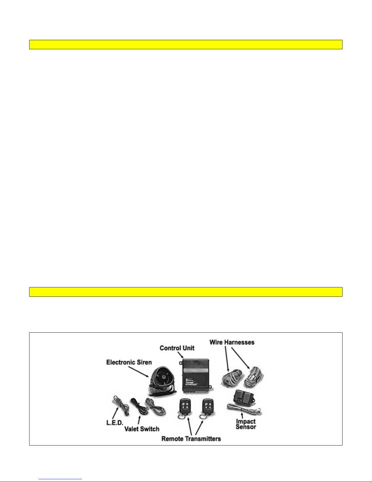
A Basic Remote Start System
Copyrght 2002-2004 Triple S Customs 27
Page 28

CAR ALARM AND REMOTE START INSTALLATION GUIDE
NOTE: This is only an example. Much more complex and much more simple systems exist, but this example is a
starting point to build an understanding of alarm and remote start systems.
CCOONNTTRROOLL UUNNIITT
The control unit or “brain” of the alarm and remote start system is the heart of the system. This is often a black
box that all harnesses and components connect to. The control unit is where the processing of various input and
output functions takes place. The control unit monitors signals from trigger inputs and sensor outputs to trigger the
alarm. The control unit also monitors signals from the remote transmitters to arm or disarm the system, lock and
unlock the doors, remote start the vehicle, or operate other accessories such as the horn or trunk release.
WWIIRRIINNGG HHAARRNNEESSSS
The wiring harness may consist of one or more separate harnesses that plug into the control unit and connect to
various vehicle circuits, sensors, or switches. NOT EVERY WIRE IS USED OR CONNECTED. Alarm and remote
start systems are designed to integrate with a wide range of vehicles with many different types of circuits.
REMOTE TRANSMITTERS
One or more remote transmitters are used to control the various functions of the alarm or remote start system.
ELECTRONIC SIREN
Security systems and some remote start systems include an electronic siren. Most sirens have a positive and a
negative wire. The negative wire connects to chassis ground and the positive wire connects to the alarm’s siren
output wire. The electronic siren is the system’s sounding device. The system sounds the siren when the system
is armed or disarmed or when the alarm is triggered. Some electronic sirens have a self-contained battery to
power the siren if power to the alarm is disconnected.
VALET SWITCH
The valet switch is used for a variety of functions depending on the complexity of the system. The valet switch
connects to the control unit through a small harness. Generally, the valet switch is a momentary switch that plugs
into the system’s control unit. The valet switch supports functions of programming, sensor disable, and system
override.
L.E.D.
The L.E.D. (light emitting diode) shows visual status of the system. It connects to the control unit usually through
a small harness. It primarily serves as a theft deterrent. The L.E.D. shows that the system is armed and warns
potential thieves.
EXTERNAL SENSORS
Many security systems include external sensors, such as an external shock sensor. They connect to the system’s
control unit through a wire, cable, or ribbon harness. External sensors offer increased protection through their
ability to be mounted in locations where they would best detect a disturbance to the vehicle.
EXTENDED RANGE ANTENNA
Some systems include an extended range antenna. Generally the antenna is mounted on the windshield and
provides the user the benefit of increased range to control functions of the alarm or remote start.
Copyrght 2002-2004 Triple S Customs 28
Page 29
CAR ALARM AND REMOTE START INSTALLATION GUIDE
INTRODUCTION TO DIODES:
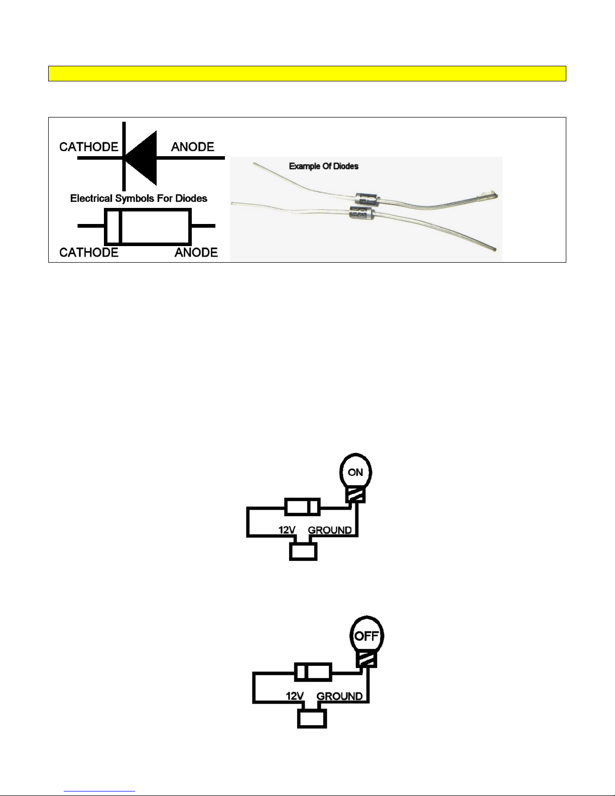
• A diode is a device designed to allow electron flow in one direction only.
When installing an alarm or remote start, diodes may be required to complete the installation. Diodes are primarily
used to isolate independent circuits from each other. Diodes will not be required on every installation, but it is still
a good idea to have a pack of 6-amp diodes on hand just in case.
• A diode has two terminals called the anode and cathode. The silver band of the diode indicates the cathode
side of the diode. Negative current flows through the cathode and out the anode but will not flow in the
opposite direction. Also, positive current flows through the anode side and out the cathode side.
• The concept of diodes is easy to understand with the help of the following illustrations. The first illustration
consists of a battery, a light bulb, and a diode. The positive terminal of the battery is connected to the anode
side of the diode. When the diode is connected this way, positive current is allowed to flow through the diode.
A diode connected to allow positive current to flow is called forward biased. Also, the cathode side of the
diode is wired to one terminal of the light bulb and the other terminal of the light bulb is connected to the
negative terminal of the battery. This completes the circuit, positive current is allowed to flow through the
diode to the light bulb and back to the battery’s negative terminal, and the light bulb will illuminate.
• In the second illustration, the diode has been reversed. The positive terminal of the battery is connected to the
cathode side of the diode. When the diode is connected this way, positive current is NOT allowed to flow
through the diode. A diode connected to block positive current to flow is called reverse biased. This prevents
the circuit from being completed and causes an open circuit. This prevents the light bulb from illuminating.
Copyrght 2002-2004 Triple S Customs 29
Page 30
CAR ALARM AND REMOTE START INSTALLATION GUIDE
INTRODUCTION TO RESISTORS:
• A resistor is an electrical component designed to have a specific resistance (or opposition) to the flow of
electrons, measured in ohms (Ω).
• When installing a remote start or security system, resistors of a specific resistance may be needed to
interface with the vehicle’s circuits. Some of a vehicle’s circuits may require a reduced voltage to operate a
specific accessory or function. A resistor can be added to reduce the trigger voltage to the circuit. Resistors
will not be required on most installations, but will be required for installations on many newer vehicles. For
example, on a 2002 Dodge Intrepid, a positive pulse through a 2700-Ohm resistor to the door lock wire will
lock the doors. If resistors are not included with the system you purchased, they can be found at almost any
electronics parts store such as Radio Shack.
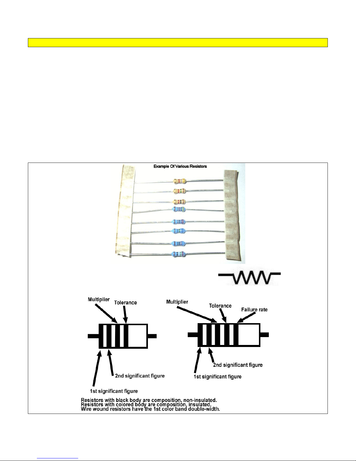
• Carbon-film resistors are the type most commonly used in vehicle security and convenience applications.
Color bands on the resistor will indicate the value in ohms as well as its tolerance in a plus or minus
percentage of accuracy. Resistors also have a watt rating to indicate the amount of power it can handle. If you
exceed the power rating of a resistor, it will overheat and burn.
Symbol used in wiring schematics to indicate a resistor:
Copyrght 2002-2004 Triple S Customs 30
Page 31
CAR ALARM AND REMOTE START INSTALLATION GUIDE
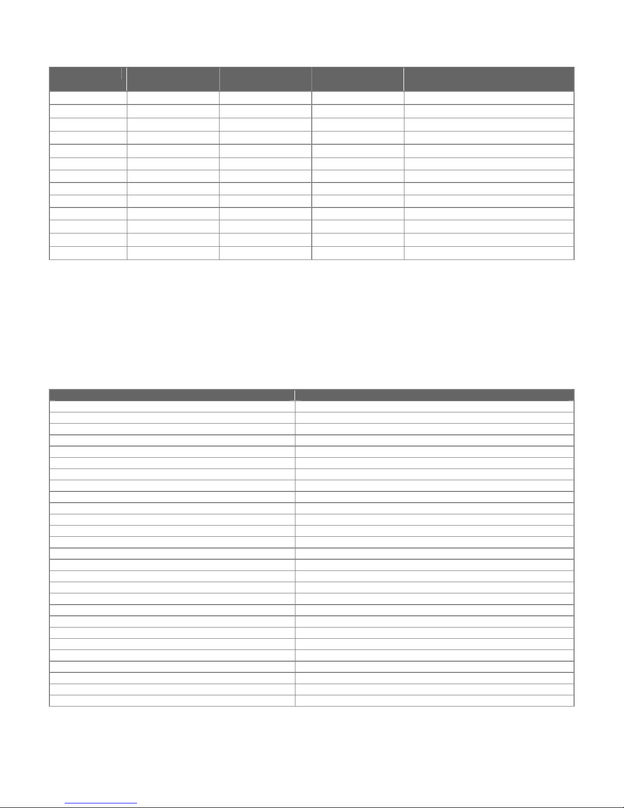
RESISTOR COLOR CODES
COLOR SIGNIFICANT
FIGURES
BLACK 0 1
BROWN 1 10
RED 2 100
ORANGE 3 1,000
YELLOW 4 10,000
MULTIPLIER TOLERANCE FAILURE RATE (% of failure per
1000 hours of operation)
± 20%
± 1%
± 2%
± 3%
± 4%
-
1.0
0.1
0.01
0.001
GREEN 5 100,000 - BLUE 6 1,000,000 - VIOLET 7 10,000,000 - GRAY 8 100,000,000 - WHITE 9 9 Solderable
GOLD - .01
SILVER - 0.01
NO COLOR -
± 5%
± 10%
± 20%
-
-
-
EXAMPLE:
st
If the 1
band is ORANGE and the 2nd band is GREEN and the 3
ORANGE 1
st
band=3, GREEN 2nd band=5, RED 3rd band=100, GOLD 4th band=5% so:
rd
band is RED and the 4th band is GOLD then:
35X100=3500 RESISTOR VALUE IS 3500 OHMS WITH A TOLERANCE OF 5%.
TROUBLESHOOTING RESISTORS:
Troubleshooting resistors is pretty straightforward. Resistors almost always open when they go bad. An open
resistor in a series circuit will stop current from flowing in the circuit. An open resistor in a parallel circuit will
increase the resistance and decrease the total current.
RESISTOR VALUE COLOR BANDS
249 OHMS RED YELLOW WHITE BLACK BROWN
330 OHMS ORANGE ORANGE BROWN GOLD
365 OHMS ORANGE BLUE GREEN BLACK BROWN
390 OHMS ORANGE WHITE BROWN GOLD
430 OHMS YELLOW ORANGE BROWN GOLD
470 OHMS YELLOW VIOLET BROWN GOLD
487 OHMS YELLOW GRAY VIOLET BLACK BROWN
560 OHMS GREEN BLUE BROWN GOLD
620 OHMS BLUE RED BLACK BLACK BROWN
665 OHMS BLUE BLUE GREEN BLACK BROWN
750 OHMS VIOLET GREEN BROWN GOLD
820 OHMS GRAY RED BROWN GOLD
867 OHMS GRAY BLUE VIOLET BLACK BROWN
931 OHMS WHITE ORANGE BROWN BLACK BROWN
1000 OHMS BROWN BLACK RED GOLD
1200 OHMS BROWN RED RED GOLD
1500 OHMS BROWN GREEN RED GOLD
1870 OHMS BROWN GRAY VIOLET BROWN BROWN
2000 OHMS RED BLACK RED GOLD
2700 OHMS RED VIOLET BLACK BROWN BROWN
3000 OHMS ORANGE BLACK RED GOLD
4020 OHMS YELLOW BLACK RED BROWN BROWN
4700 OHMS YELLOW VIOLET RED GOLD
5360 OHMS GREEN ORANGE BLUE BROWN BROWN
7150 OHMS VIOLET BROWN GREEN BROWN BROWN
7500 OHMS VIOLET GREEN RED GOLD
9100 OHMS WHITE BROWN RED GOLD
Copyrght 2002-2004 Triple S Customs 31
Page 32
CAR ALARM AND REMOTE START INSTALLATION GUIDE
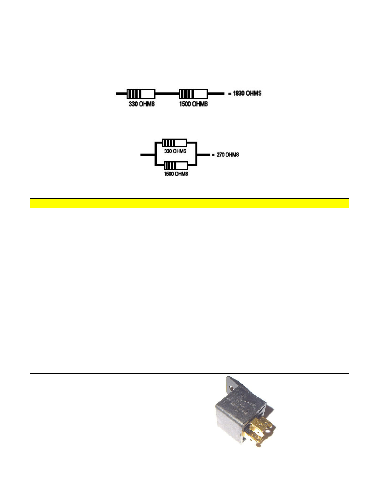
In some cases, you’ll need a resistor of a value other than what you have available. Different resistance values
can be obtained by combining the resistors in a series or parallel connection.
Series Connection
When two or more resistors are wired in series, the total value is the sum of the resistor values.
R1 + R2 = Total resistance value
Parallel Connection
When two or more resistors are wired in parallel, the total value is the total of the value of the first resistor
multiplied by the second resistor divided by the sum of the first resistor and the second resistor.
(R1 X R2) ÷ (R1 + R2) = Total resistance value
INTRODUCTION TO RELAYS;
• A relay is nothing more than a switch. A relay is an electrmechanical switch. Simply put, a relay will be used
for an alarm or remote start installation for one or more of the four purposes:
o To turn something ON
o To turn something OFF or disable something
o To change the polarity of a wire
o To increase the current supply of a wire.
• Relays involve the simple matter of switching. The difference between a switch that you turn on or off with
your finger and a relay is the method of activation. You use your finger to turn a switch on or off, but a relay is
activated electronically. This is how a car alarm or remote start system’s functions can operate without having
someone to turn a switch manually.
• Relays are often used in alarm or remote start installations to control functions like:
o Starter interrupts or disables
o Power door locks
o Flashing parking lights
o Power trunk, power hatch, or power fuel door releases
o Horn honk
o Multiple triggers
o Garage door openers
o Power window/sunroof control
Example of a Bosch SPDT 30-amp relay:
Copyrght 2002-2004 Triple S Customs 32
Page 33
CAR ALARM AND REMOTE START INSTALLATION GUIDE
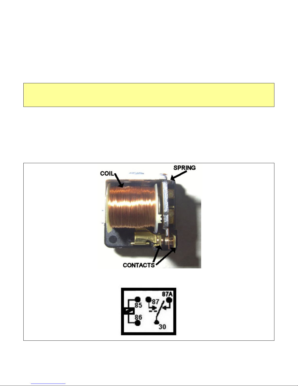
3 parts make up a standard relay. They are known as the COIL, CONTACTS, and the SPRING.
COIL:
• This is the part of the switch that allows the relay to be controlled electronically instead of by someone
pressing a button or flipping a switch. The coil of a relay is made up of many turns of small gauge wire
wrapped around an iron core. When the coil is energized it creates a magnetic field.
• Pins 85 and 86 make up the terminals of the coil. When 12V is connected to pin 86 and ground is connected
to pin 85, the coil is activated.
NOTE: Usually, it doesn’t matter whether pin 85 or 86 is used for 12V or ground. But if the relay has an
INTERNAL SPIKE SUPPRESSION DIODE, 85 must be the negative terminal and 86 must be the positive
terminal. Most OEM vehicle relays are wired this way and it is a good habit of always using 85 for the negative
terminal and 86 for the positive terminal.
CONTACTS:
These are the terminals that connect into the vehicle’s electrical system. Functions include turning a vehicle on/off
or disabling it, changing a wire’s polarity, or increasing the current. Depending on if the coil is energized or not,
pin 30 will be connected to either pin 87 or pin 87A.
SPRING:
This is the part of the relay that keeps the common (pin 30) and the normally closed contact (pin 87a) connected
while the coil is not energized. Magnetic force created by the energized coil will connect the common (pin 30) to
the normally open contact (pin 87)
AA llooookk iinnssiiddee aa rreellaayy
This is a schematic of a relay. A similar schematic is printed on the side of most relays.
Copyrght 2002-2004 Triple S Customs 33
Page 34
CAR ALARM AND REMOTE START INSTALLATION GUIDE
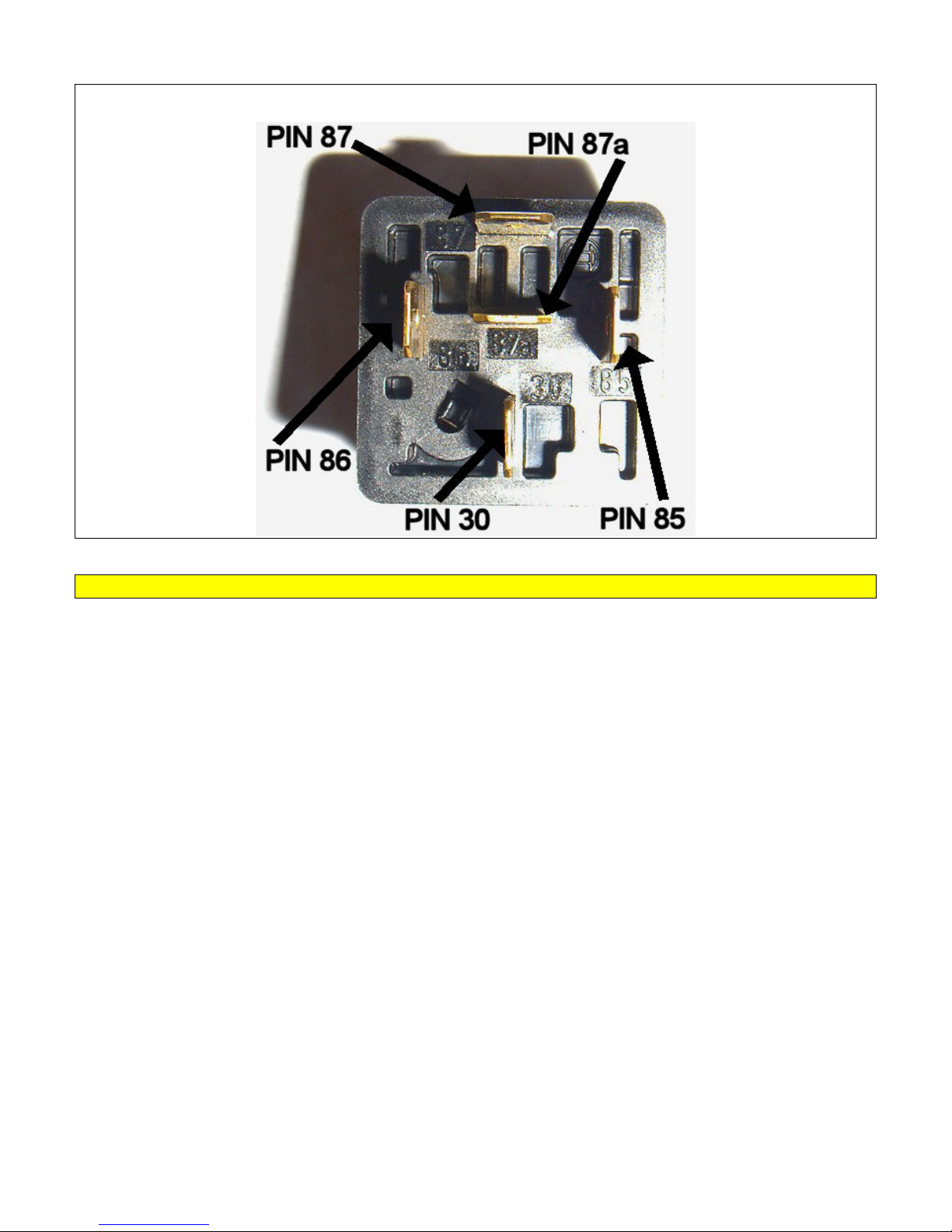
This is a look at the back of a relay. Actual connections are connected to these terminals or a custom wired
harness is plugged into the back of the relay.
BEFORE BEGINNING THE INSTALLATION:
• READ ALL INSTRUCTIONS!
• Take time to check out the vehicle thoroughly. Check what electrical items work and what items don’t work. It
helps to have someone help you with this to properly check the vehicle’s brake lights, reverse lights, turn
signals, hazard lights, parking lights, fog lights, and headlights. This may bring to your attention problems you
were not previously aware of and prevent unnecessary troubleshooting when the installation is completed.
• Check the contents of the alarm or remote start system that you will be installing. Make sure the system is
complete and that no components are visibly damaged.
• Consider what options will be installed. Many alarm and remote start systems have the option and ability for
features such as starter kill, keyless entry, trunk release, horn honk, and dome light supervision. Some
options will require additional parts or relays. It is always easier to install features when the system is first
installed than later.
• Plan and allow extra time to complete the installation. Most professional installers will admit that their first
security installation took 6-10 hours. It is recommended to schedule yourself a weekend to complete the
installation so you do not feel rushed.
• Set up to do the installation in a sheltered, dry, and well-lit area where you will not be disturbed or bothered by
other people or pets.
• Turn off the dome light. This prevents draining the battery while you complete the installation. If your vehicle
does not have a dome light switch, you can remove the dome light bulb itself. Consult your vehicle’s owner’s
manual on the best procedure to do this. Be careful, as the bulb gets very hot in a short time.
• Roll down the windows to avoid being accidentally locked out of the vehicle.
• Protect the vehicle by using floor mats, seat covers, and fender covers. It is also recommended to place an
old rug or blanket on the floor on the driver’s side of the vehicle. This will help lessen the strain on your knees
and prevent any screws, clips, or small parts accidentally dropped from bouncing across the floor.
• Remove any watches, rings, or jewelry. This will help prevent accidentally scratching or damaging the vehicle
or damaging the jewelry itself. Avoid wearing a belt or pants with rivets, metal zippers, or metal buttons that
could scratch or damage the vehicle.
Copyrght 2002-2004 Triple S Customs 34
Page 35

CAR ALARM AND REMOTE START INSTALLATION GUIDE
TOOLS AND ADDITIONAL PARTS REQUIRED;
COMMON TOOLS REQUIRED:
• Digital Multi-meter (never use a test light or analog meter to test automotive circuits)
• Wire cutters
• Wire strippers
• Quality wire crimping tool- such as Klein or Snap-On
• Soldering iron
• Cordless power drill
• Nut drivers or socket set in both metric and standard sizes.
• Drill bit set, 1/2" Unibit
• Torx bit set
• Allen bit set
• Phillips head screwdriver
• Small flathead screwdriver (for adjusting sensors)
• Panel removal tool (Available at most auto parts stores)
• Razor blades
• Droplight or flashlight
• Metal coat hanger (used to feed wires through rubber grommet in firewall)
ADDITIONAL PARTS AND MATERIALS OFTEN REQUIRED:
NOTE: Many of these parts or materials may be purchased at Radio Shack or better-equipped hardware stores.
• 3M vinyl electrical tape- 2 or 3 rolls
• Heat shrink tubing
• Plastic wire ties or zip ties in various lengths
• Vinyl split loom or tubing to conceal and protect wiring under the hood
• 60/40 resin core solder
• 12V 30A SPDT relays- the number of relays required will vary depending on the system being installed and
the features or options installed with it.
• Door lock actuators- required only if adding remote keyless entry to vehicles without power door locks
• Pack of insulated butt connectors
• Pack of 6 amp diodes
• Pack of resistors of various impedances
• Spring-loaded pin switch- necessary if installing an under hood pin switch
• Immobilizer bypass module- only available at better-equipped car audio stores- required when installing a
remote start on vehicles equipped with a factory immobilizer. Check your vehicle’s owner’s manual or this
document to help you determine if your vehicle is equipped with a factory immobilizer system.
WIRING THE SYSTEM AND MAKING YOUR CONNECTIONS;
• What makes or breaks an alarm or remote start system is the installation. Even the best systems on the
market will not properly protect a vehicle and function properly if they are poorly installed. A properly installed
system begins with how the system’s wiring is prepared.
• Most installers prefer to disassemble the vehicle first and find the wires they need before any
components are mounted or connections are made. It is recommended that when disassembling the
vehicle; place each part in a labeled box or bin. Do not leave pieces on the floor. They could get lost,
stepped on, or broken.
o It is recommended that the proper tool be always used to disassemble and reassemble parts
of the vehicle. Many tool companies make specialized tools such as window crank removal
tools and door panel removal tools that are available at better-equipped auto parts stores and
hardware stores.
o It is recommended that parts be placed in a labeled box or bag. This helps prevent parts from
being lost, stepped on, or broken. This will also help make reassembly easier.
Copyrght 2002-2004 Triple S Customs 35
Page 36

CAR ALARM AND REMOTE START INSTALLATION GUIDE
• Take time to test each wire to verify that it is the correct wire. Use a quality digital multi-meter. A digital multi-
meter is a multi-purpose instrument that combines the features of an ammeter, voltmeter, and ohmmeter into
one tool. Never use an analog volt-ohm meter or incandescent test light to test circuits. In today’s computer
equipped vehicles, the current draw that a volt-ohm meter or test light requires can permanently damage
delicate vehicle computers. Always use a digital multi-meter to test circuits. Wire colors and sometimes wire
polarities can vary from vehicle to vehicle. Also, take a note of how the vehicle’s factory wires are wrapped.
Are they wrapped in vinyl tape? Are they covered in split-loom? Are they covered in cloth tape? Wires should
be carefully wrapped to match the vehicle's wiring. This will make the system “blend in” with the factory
wiring, giving it a factory-installed appearance.
• Study the vehicle and find places to mount components such as the control unit, relays, and sensors. Make
sure components won’t be in the way of any moving parts. Make sure you can reassemble the vehicle without
the alarm/remote start system’s components being in the way. Nothing is worse than completing the
installation and finding a panel won’t fit back on because a relay or the control unit is in the way. Look under
the hood to find a spot to mount the siren. Many engine bays are very cramped. Take time to plan how you
will run your wires through the engine bay.
• Most installers prefer to screw down or use double-sided tape to secure the system’s control module on a
counter top or work bench to prep the system’s wiring. Some installers chose to wrap the system’s wires
individually. However, many systems can have over 50 wires. In this case many installers will wrap wires that
must go to a similar location together. For example, twist together wires that must go to a similar location like
the driver’s kick panel, the ignition harness, the passenger kick panel, the headlight switch, under the hood, or
to any other location that you are routing wires to. Wrap the wires in tape or split loom to camouflage the
wires and make them look like factory wiring. Cap off wires that will not be connected to prevent any shorts.
• Connections should only be made by crimp connectors or solder connections. When properly performed, both
connections are reliable and trouble free.
• It is recommended that a Klein-style crimp tool be used for solderless crimp-on connectors instead of a cheap
hardware store crimping tool. When making crimp connections, the seam of the metal barrel in the solderless
crimp-on connector should be in the concave part of the crimp tool’s jaws.
• When soldering, solder should be applied so it flows over the connections. For best results, the tip of the
soldering iron should be held below the wire while applying the solder from above. This allows the solder to
flow from the top of the wire to the bottom more uniformly. Two or three balls of solder is not good enough
because it may contain air bubbles and either brake off over time or have little electrical connection value. A
good solder joint should be smooth and shiny. Once the soldering is completed, let the solder joint stand until
cool. Tape and seal the solder joint after the solder joint has cooled.
• When soldering, use a drop cloth to prevent solder drips and burns on the vehicle's carpeting. Also a drop
cloth makes clean up easier when installation is completed.
• Make certain that wires cannot be shorted to the chassis at any point.
• Use good-quality electrical tape; such as 3M, or heat shrink tubing
• Never twist-and-tape wires together without soldering. Never use “wire nuts.” Wire nuts are designed for a
stationary, stable environment. The vibration of being on the road could cause a wire nut to eventually fall off
the wire leaving the exposed wiring to short to ground, possibly causing severe electrical damage.
• Never use "fuse taps".
• Avoid using T-taps, especially in high current connections. Many installers get in the habit of using T-taps
because they are quick and easy to use. However, over time they can come loose. Also they are not meant to
be used in high-current connections such as the outputs from a remote start system to the vehicles ignition,
accessory, and starter wires.
HOW TO TEST THE VEHICLE’S WIRING
WARNING! Do not use a 12V test light to locate or test any wires! A test light may cause serious
damage to vehicle electronics. Only use a digital multi-meter to test circuits.
TESTING THE TACHOMETER WIRE:
• A multi-meter capable of testing AC voltage is needed to test for the tachometer wire.
• The tachometer wire will meter between 1V and 6V AC.
• Common locations for the tachometer are the ignition coil, instrument cluster, engine computers, or test
connector.
Copyrght 2002-2004 Triple S Customs 36
Page 37
CAR ALARM AND REMOTE START INSTALLATION GUIDE
WARNING! Do not test tachometer wires with a test light or logic probe. The vehicle WILL BE DAMAGED.
To find a tachometer wire with a multi-meter:
1. Set meter to AC voltage.
2. Attach the (-) probe of the meter to chassis ground.
3. Start and run the vehicle
4. Probe the wire suspected of being the tachometer wire with the other probe.
5. If this is the correct wire, the meter will read between 1V and 6V.
? Having trouble finding a tachometer wire?
• On some vehicles, the ignition coil may be difficult to reach.
• Many vehicles have a tachometer wire available behind the instrument cluster.
• A fuel injector wire can also be used for a tachometer signal on most vehicles. Each injector will have two
wires. Use the wire that is not common. For example, at one injector the wires may be BLACK/WHITE and
RED. At the next injector the wires may be GREEN/WHITE and RED. At the next injector the wires may be
BLUE/RED and RED. At the next injector wires may be PURPLE/WHITE and RED. In this case you would
use any wire that is not RED.
TESTING THE HOOD PIN WIRE
• Generally, models equipped with a factory security system have a factory hood pin switch.
• This wire can often be found at the factory anti-theft unit or at the hood pin switch.
To find the hood pin trigger wire with your multi-meter:
1. Set to DC voltage
2. Attach the (+) probe to 12V constant
3. Probe the wire you suspect of being the hood trigger wire with the (-) lead
4. The meter should indicate 12V with the hood open if you have found the correct wire
5. The meter will then read 0V when the hood is closed.
TESTING THE IGNITION WIRE
• The ignition wire is often found in the harness coming from the key cylinder.
• This wire is powered when the key is in the run or start position.
• This wire powers the ignition system and the fuel delivery system.
To find 12V ignition with a multi-meter:
1. Set meter to DC voltage
2. Attach the (-) probe of the meter to chassis ground
3. Probe the wire you suspect of being the ignition wire with the (+) probe. The steering column harness or
ignition harness is an excellent place to find this wire.
4. Turn the ignition key to the run position. If your meter reads 12V go to the next step
5. Turn the key to the start position. The meter should remain steady. If it drops close to or all the way to zero,
that is not the correct wire. Go back to step 3. If it stays steady at 12V that is the ignition wire.
NOTE: Some vehicles have more than one ignition wire that must be energized for the remote start process in
order for the vehicle to run properly. If the system only has one (+) ignition output, use a relay for each additional
ignition wire that must be energized.
Copyrght 2002-2004 Triple S Customs 37
Page 38
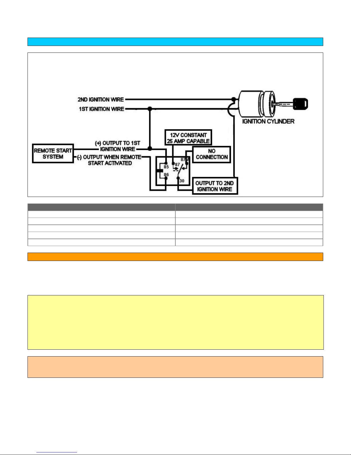
CAR ALARM AND REMOTE START INSTALLATION GUIDE
WIRING A RELAY FOR SECOND OR THIRD IGNITION
NEVER connect two Ignition wires of the vehicle together to avoid using a relay. If the vehicle
manufacturer wanted the Ignition 1 and 2 wires to be summed, they would have done it at the factory!
This is not only unwise because of the current draw issues, but this is a perfect opportunity for the dealer
to call the warranty void if ANYTHING relating to the electrical system goes wrong.
PIN CONNECTION
85 (+) OUTPUT TO 1ST IGNITION WIRE
86 (-) OUTPUT WHEN REMOTE START IS ACTIVATED
87 12V CONSTANT FUSED 25 AMP CAPABLE
87A NO CONNECTION
30 TO (+) SECOND IGNITION WIRE
TESTING THE 12V ACCESSORY WIRE:
• This wire is powered when the key is in the accessory and run position.
• This wire will not show 12V during the cranking cycle.
• Most often found in the harness coming from the key cylinder.
To find 12V accessory with a multi-meter:
1. Set meter to DC voltage
2. Attach the (-) probe of the meter to chassis ground
3. Probe the wire you suspect of being the accessory wire with the (+) probe. The steering column harness or
ignition harness is an excellent place to find this wire.
4. Turn the ignition key to the accessory and then the run position. If your meter reads 12V on each, go to the
next step
5. Turn the key to the start position. The meter should drop to zero. If it does, this is the correct wire.
NOTE: Some vehicles have more than one accessory wire that must be energized for the remote start process in
order for the vehicle to run properly. If the system only has one (+) accessory output, use a relay for each
additional accessory wire that must be energized and wire as shown:
Copyrght 2002-2004 Triple S Customs 38
Page 39
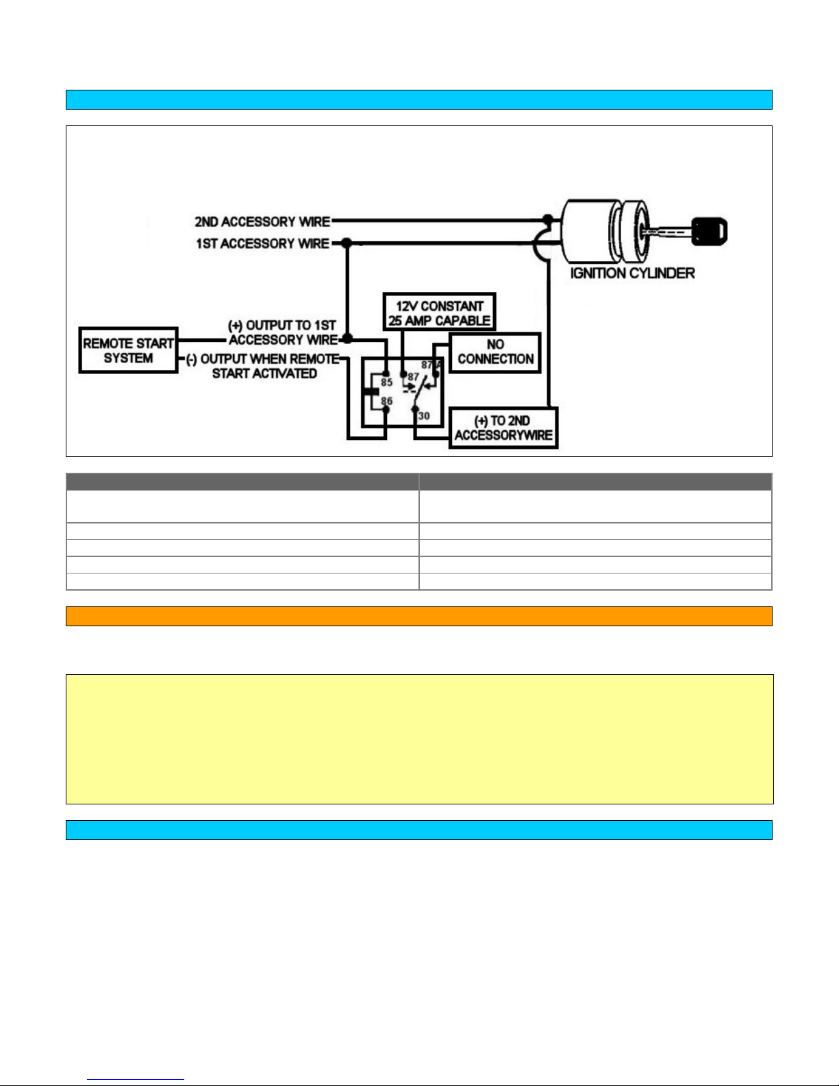
CAR ALARM AND REMOTE START INSTALLATION GUIDE
WIRING A RELAY FOR SECOND OR THIRD ACCESSORY
NEVER connect two Accessory wires of the vehicle together to avoid using a relay. If the vehicle
manufacturer wanted the Accessory 1and 2 wires to be summed, they would have done it at the factory!
This is not only unwise because of the current draw issues, but this is a perfect opportunity for the dealer
to call the warranty void if ANYTHING relating to the electrical system goes wrong.
PIN CONNECTION
85 (+) OUTPUT FROM REMOTE START TO 1ST
ACCESSORY WIRE
86 (-) OUTPUT WHEN REMOTE STARTED
87 12V CONSTANT FUSED 25 AMP CAPABLE
87A NO CONNECTION
30 TO (+) SECOND ACCESSORY WIRE
TESTING THE STARTER WIRE
• The starter wire is often found in the harness coming from the key cylinder.
To find the starter wire with your multi-meter:
1. Set your meter to DC voltage
2. Attach the (-) probe to chassis ground.
3. Probe the wire you suspect of being the starter wire with the (+) probe.
4. Turn the key to the start position. If the meter reads 12V go to the next step
5. Cut the wire you suspect of being the starter wire
6. Attempt to start the car. If the starter engages, reconnect it and go back to step 3. If the starter does not
engage, that is the correct wire.
WIRING A RELAY FOR STARTER DISABLE
• Most security systems include a starter disable. The security system controls a relay that interrupts the flow of
power to the starter solenoid when the alarm is armed and an attempt is made to start the vehicle. However, it
is important to note that if the vehicle has a manual transmission, this will not prevent the vehicle from being
“roll started.”
• Solid wire connections must be made. For maximum dependability, solder and shrink tube the connections.
• Wires should be wrapped in 3M electrical tape or plastic tubing to match the factory wiring.
Copyrght 2002-2004 Triple S Customs 39
Page 40
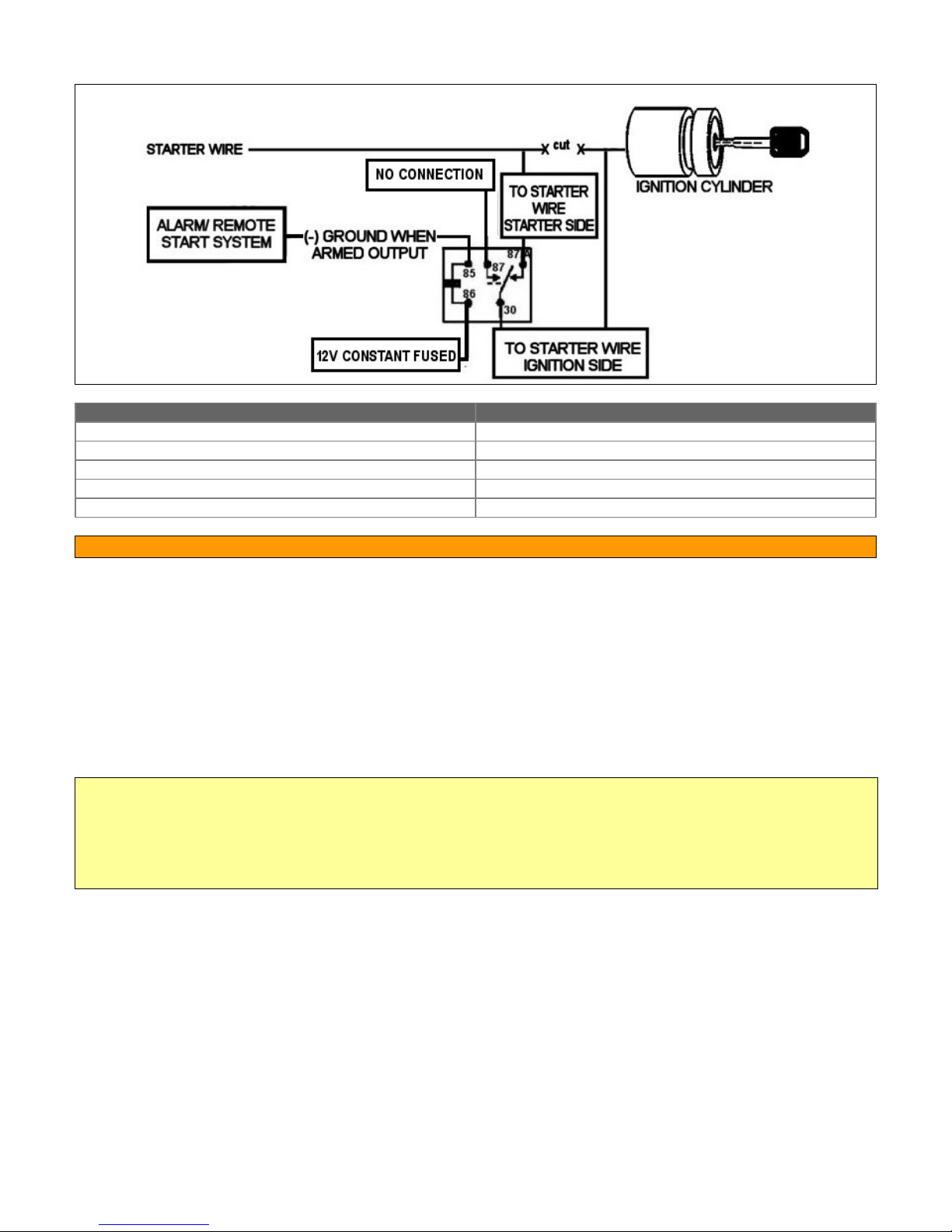
CAR ALARM AND REMOTE START INSTALLATION GUIDE
If the system does not come pre-wired for a starter disable, use a relay and wire as shown:
PIN CONNECTION
85 (-) GROUND WHEN ARMED OUTPUT
86 12V CONSTANT FUSED
87 NO CONNECTION
87A STARTER WIRE- IGNITION SWITCH SIDE
30 STARTER WIRE- STARTER SIDE
TESTING THE WAIT-TO-START WIRE FOR DIESEL VEHICLES
• Most remote start systems have the ability to be installed on a diesel vehicle. Check the installation manual
included with the remote start system. Some systems can simply be programmed to be compatible with a
diesel vehicle. Other systems have a (-) WAIT-TO-START INPUT wire that must be connected to be
compatible with a diesel vehicle.
• For systems with a (-) WAIT-TO-START INPUT wire it is necessary to interface with the wire that turns on the
WAIT-TO-START light in the dashboard. This wire illuminates the bulb until the vehicle's glow plugs are
properly heated. When the light goes out the vehicle can be started.
• This wire is always available at the connector leading to the bulb in the dashboard.
• Connect this wire from the remote start system to the wire in the vehicle that sends the signal to turn
on the WAIT-TO-START bulb in the dashboard.
To find the (-) WAIT-TO-START wire
1. Set the multi-meter to DC voltage.
2. Attach the (+) probe to 12V Constant
3. Probe the wire you suspect leads to the bulb with the (-) probe of the meter
4. Turn the ignition to the ON position
5. If the meter reads 12V until the light goes out and then reads 0V that is the correct wire.
Copyrght 2002-2004 Triple S Customs 40
Page 41
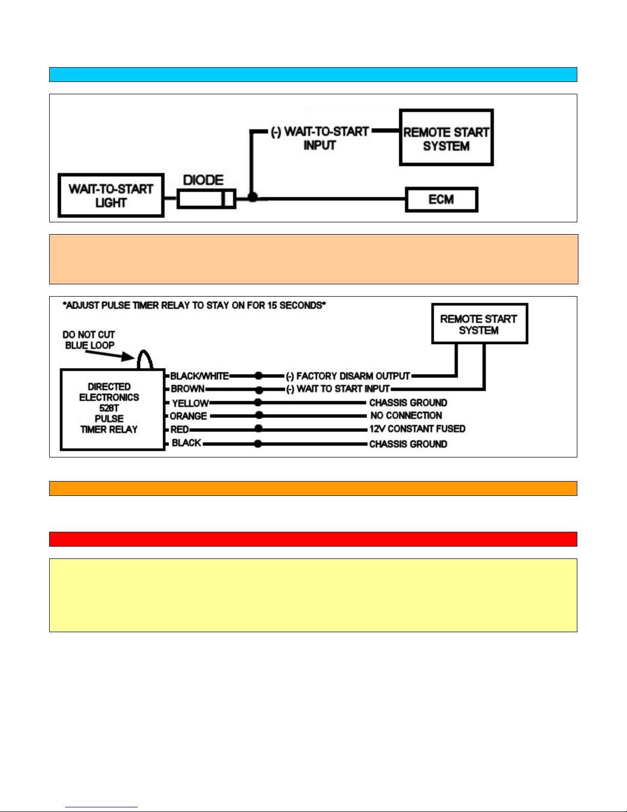
CAR ALARM AND REMOTE START INSTALLATION GUIDE
WIRING A DIODE TO INTERFACE THE WAIT-TO-START WIRE
For vehicles with a (-) WAIT-TO-START wire, use a relay and wire as shown.
NOTE: On 2002-Up diesel vehicles, the vehicle’s WAIT-TO-START wire should not be directly interfaced with.
Use a pulse timer relay to delay the remote start’s activation so the vehicle’s glow plugs can be properly heated.
Directed Electronics makes a pulse timer relay that is readily available at many car audio and security specialty
shops. Part number is 528T.
TESTING THE HORN TRIGGER:
• The horn trigger wire is usually found in one of the bundles of wires at the steering column.
NOTE: Always take care when working around the airbag wires. Do not probe or cut into them.
To find the (-) horn honk trigger wire with your multi-meter:
1. Set to DC voltage
2. Attach the (-) probe to chassis ground
3. Probe the wire you suspect of being the horn honk trigger wire with the other probe. The meter should read
12V.
4. Honk the horn. The meter should drop to 0V when the horn is honked. If it does, that is the correct wire.
Copyrght 2002-2004 Triple S Customs 41
Page 42
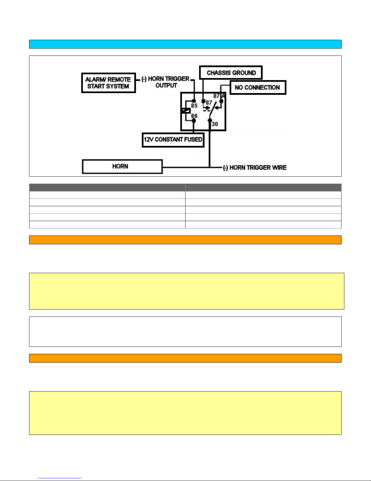
CAR ALARM AND REMOTE START INSTALLATION GUIDE
WIRING A RELAY FOR HORN HONK
In many cases a relay must be used to activate the horn. Use a relay and wire as shown:
PIN CONNECTION
85 (-) HORN TRIGGER OUTPUT
86 12V CONSTANT FUSED
87 CHASSIS GROUND
87A NOT CONNECTED
30 (-) HORN TRIGGER WIRE
TESTING THE BRAKE SWITCH WIRE:
• The brake switch wire is usually found at the brake switch or in the drivers kick panel or passenger kick panel
in a harness leading towards the rear of the vehicle.
To find the (+) brake wire with your multi-meter:
1. Set to DC voltage
2. Attach the (-) probe to chassis ground
3. Probe the wire you suspect of being the brake wire with the other probe.
4. Depress the brake pedal. The meter should read 12V with the pedal depressed and 0V with the pedal at rest.
? Having trouble finding or reaching the brake wire?
• On some vehicles, reaching the brake switch may be difficult or near impossible.
• The brake switch wire can usually also be found in the driver’s kick panel in a harness running towards
the rear of the vehicle.
TESTING THE POSITIVE DOOR TRIGGER WIRE
• Some models use a positive door trigger. This means when the door is open; the switch sends a
positive voltage to the dome light circuit.
To find the (+) door trigger wire with your multi-meter:
1. Set to DC voltage
2. Attach the (-) probe to chassis ground.
3. Probe the wire you suspect of being the door trigger wire with the (+) lead
4. The meter should indicate 12V with the door open/dome light on if you have found the correct wire.
5. The meter will then read 0V when the door closed/dome light off.
Copyrght 2002-2004 Triple S Customs 42
Page 43
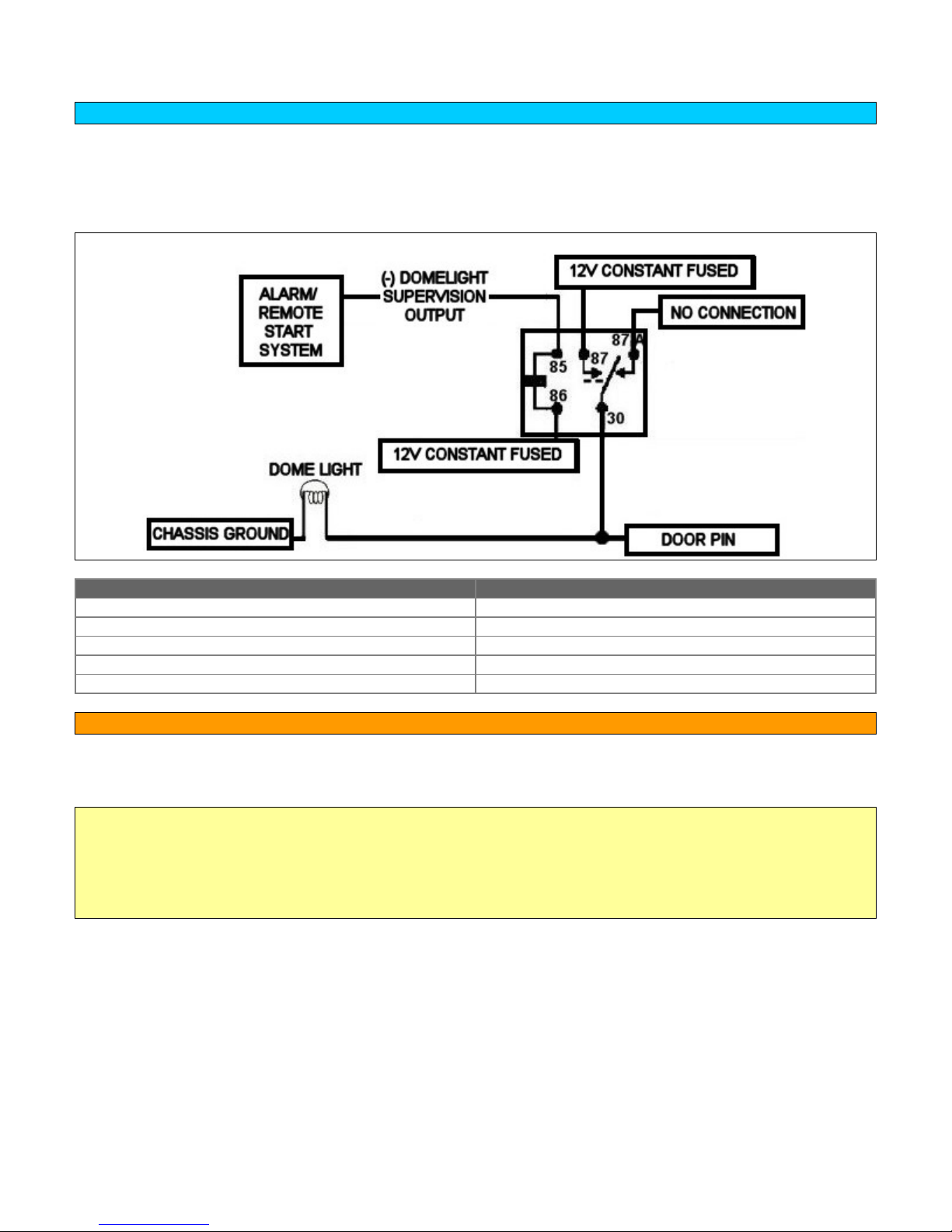
CAR ALARM AND REMOTE START INSTALLATION GUIDE
WIRING A RELAY FOR DOMELIGHT SUPERVISION (POSITIVE DOOR TRIGGER)
• Many alarm or remote start systems include the optional feature of dome light supervision. Dome light
supervision is the ability of a security system to turn on the vehicle’s interior courtesy lights or dome light for a
short time when the system is disarmed/unlocked. This allows the owner to check the interior for an intruder
before entering.
NOTE: For dome light supervision connect the dome light supervision output as shown:
PIN CONNECTION
85 (-) DOMELIGHT SUPERVISION OUTPUT
86 12V CONSTANT FUSED
87 12V CONSTANT FUSED
87A NOT CONNECTED
30 TO (+) DOMELIGHT SUPERVISION WIRE
TESTING THE NEGATIVE DOOR TRIGGER/DOMELIGHT SUPERVISION WIRE
• The door trigger wire can typically be found at the fuse box or in the driver’s kick panel. Some models may
require finding the door trigger wire in each kick panel or in one or more of the vehicle’s doors.
To find the (-) door trigger wire with your multi-meter:
1. Set to DC voltage
2. Attach the (+) probe to 12V constant
3. Probe the wire you suspect of being the door trigger wire with the (-) lead
4. The meter should indicate 12V with the door open if you have found the correct wire
5. The meter will then read 0V when the door closed.
Copyrght 2002-2004 Triple S Customs 43
Page 44
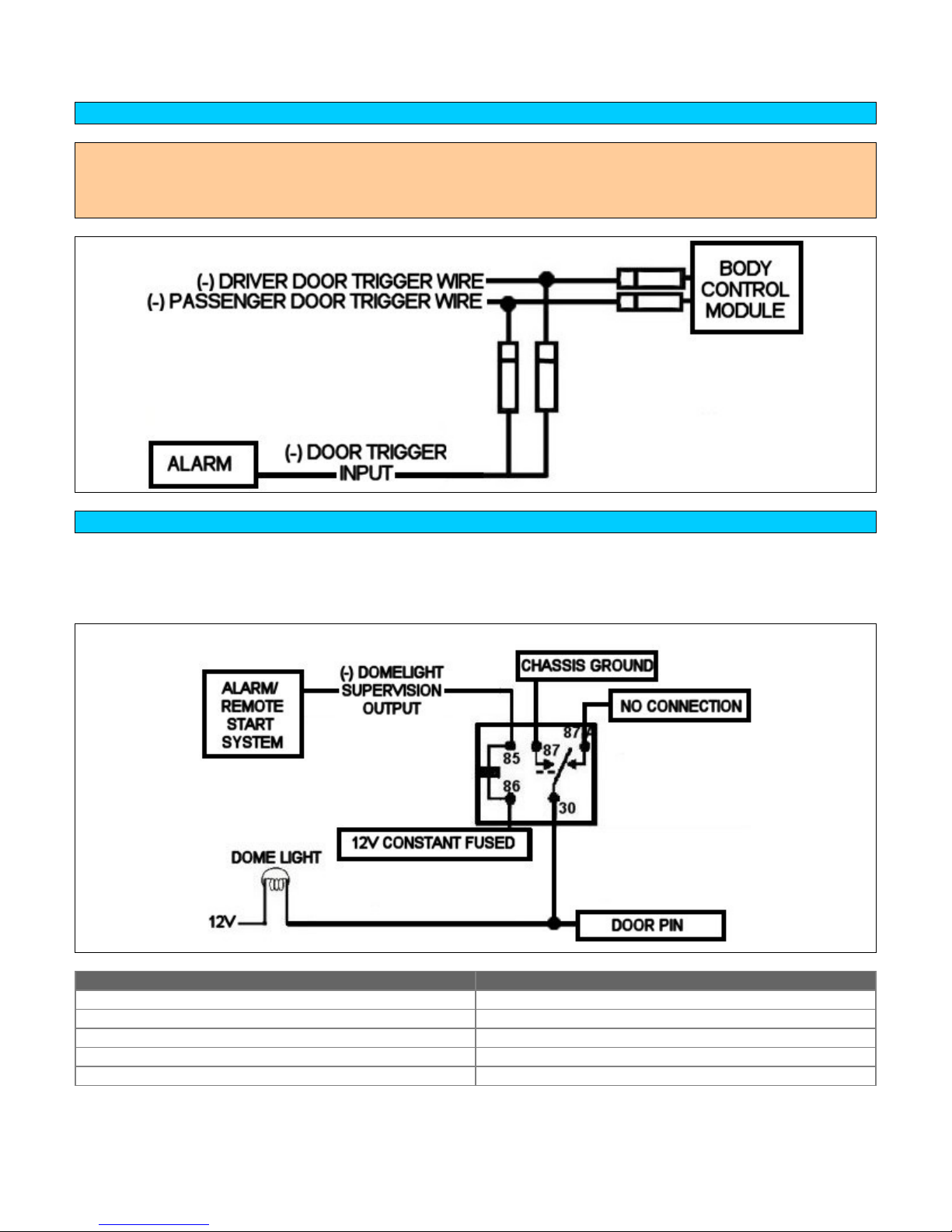
CAR ALARM AND REMOTE START INSTALLATION GUIDE
WIRING DIODES FOR VEHICLES WITH MORE THAN ONE DOOR TRIGGER WIRE
NOTE: 97-Up F-Series Light Duty Pickups have a separate door trigger wire for each door. The BLACK/YELLOW
catches the driver’s door and the BLACK/PINK catches the passenger’s door. Use both wires and diode isolate
each. The wires are found in there respective door harnesses. Both wires may also be found at the GEM module
located above the fuse box.
WIRING A RELAY FOR DOMELIGHT SUPERVISION (NEGATIVE DOOR TRIGGER)
• Most alarm and remote start systems include the option of dome light supervision. Dome light supervision will
turn on the vehicle’s dome light for a set time when the system unlocks/disarms the vehicle. This allows the
user to check the interior of the vehicle for an intruder before entering.
For dome light supervision connect the dome light supervision output as shown:
PIN CONNECTION
85 (-) DOMELIGHT SUPERVISION OUTPUT
86 12V CONSTANT FUSED
87 CHASSIS GROUND
87A NO CONNECTION
30 DOOR TRIGGER WIRE IN VEHICLE
Copyrght 2002-2004 Triple S Customs 44
Page 45
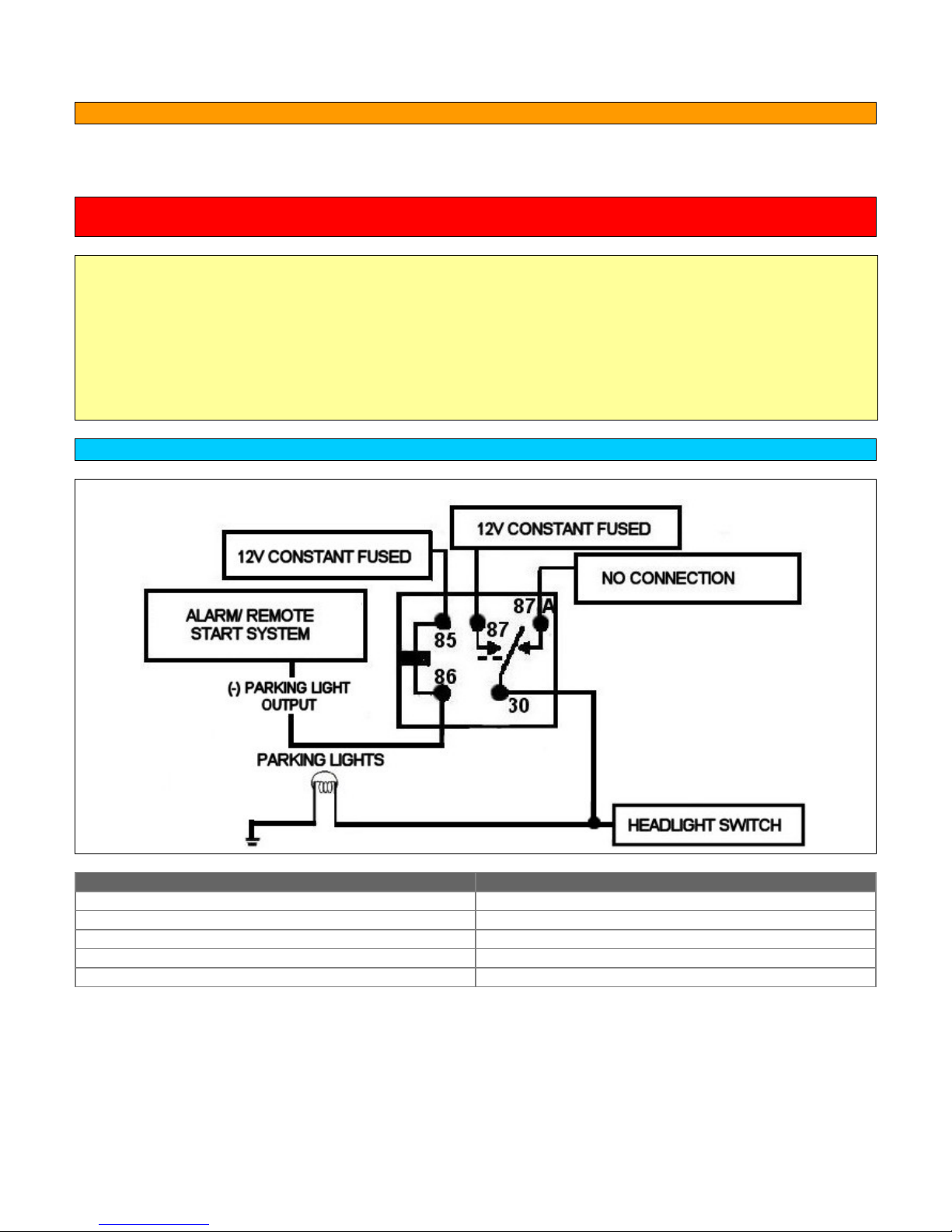
CAR ALARM AND REMOTE START INSTALLATION GUIDE
TESTING THE PARKING LIGHT WIRE
• The parking light wire can typically be found behind the headlight switch, at the fuse box, in the driver’s kick
panel, or in a harness from the steering column.
NOTE: Never connect the parking light output to the headlight circuit. Doing so may cause the headlights
to burn out prematurely
To find the parking light wire with your multi-meter:
1. Set to DC voltage
2. Attach the (-) probe to chassis ground
3. Probe the wire you suspect of being the parking light wire
4. Turn on the parking lights. If your meter shows 12V, turn off the parking lights and make sure it goes back to
zero.
5. If it does return to zero, turn the parking lights back on, and turn the dimmer up and down. If the meter
changes more than a volt when using the dimmer, look for another wire. If it stays relatively close to 12V, that
is the correct wire.
WIRING A RELAY FOR PARKING LIGHT FLASH
NOTE: If the aftermarket unit only has a (-) parking light output, use a relay and wire as shown:
PIN CONNECTION
85 12V CONSTANT FUSED
86 (-) PARKING LIGHT OUTPUT
87 12V CONSTANT FUSED
87A NOT CONNECTED
30 TO (+) PARKING LIGHT WIRE
Copyrght 2002-2004 Triple S Customs 45
Page 46
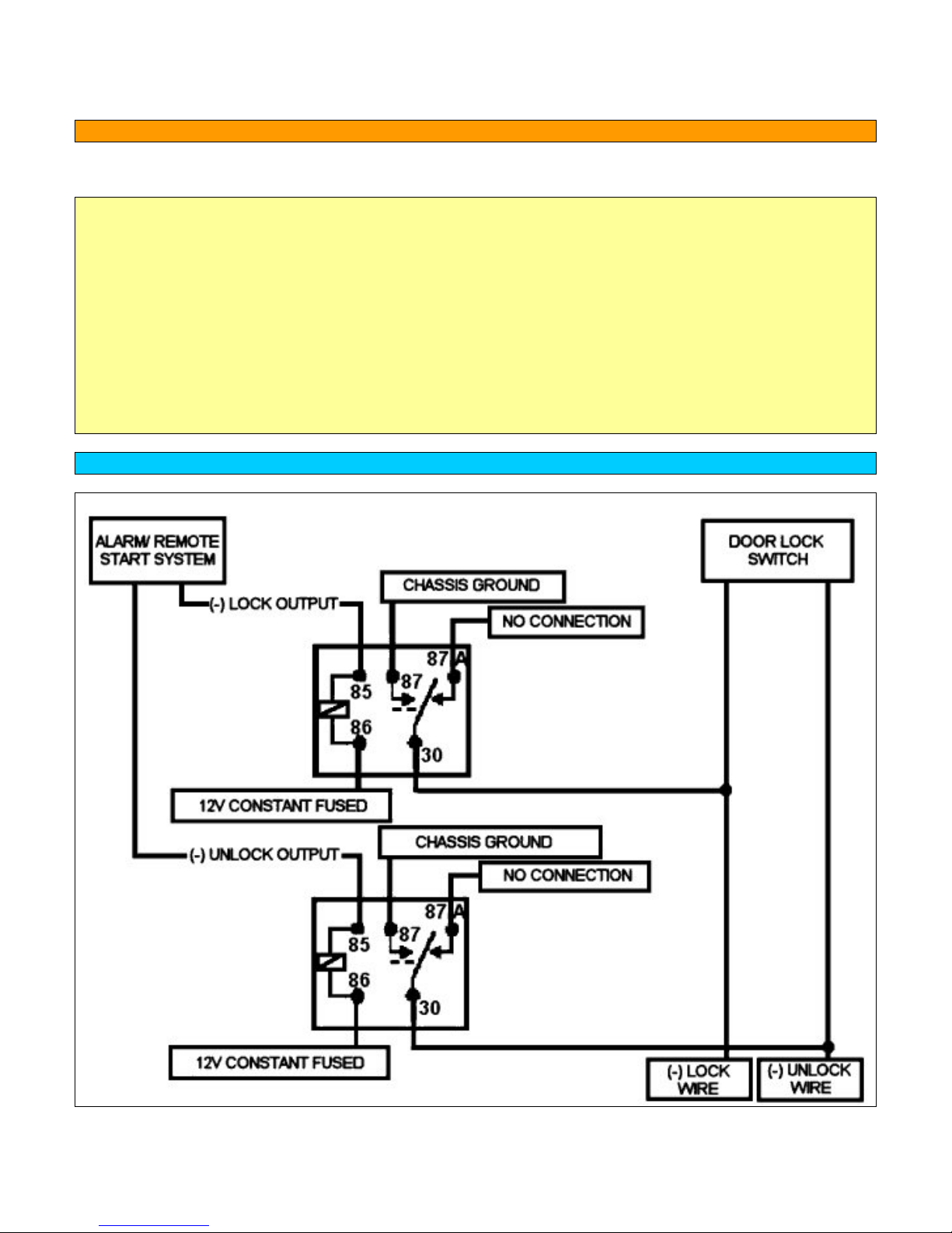
CAR ALARM AND REMOTE START INSTALLATION GUIDE
TESTING NEGATIVE TRIGGER DOORLOCKS
• Some models with power locks use a negative (-) triggered door lock system.
To find the door lock wire with your multi-meter:
1. Set to DC voltage
2. Attach the (-) probe to chassis ground
3. Probe the wire you suspect of being the door lock wire
4. When the switch is at rest, the meter should read 12V
5. Lock the door with the switch. The meter should read 0V or close to it. If it does, that is the correct wire.
To find the door unlock wire with your multi-meter:
1. Set to DC voltage
2. Attach the (-) probe to chassis ground
3. Probe the wire you suspect of being the door unlock wire
4. When the switch is at rest, the meter should read 12V
5. Unlock the door with the switch. The meter should read 0V or close to it. If it does, that is the correct wire.
WIRING RELAYS FOR NEGATIVE TRIGGER DOOR LOCKS
NOTE: Use relays and wire as shown:
Copyrght 2002-2004 Triple S Customs 46
Page 47
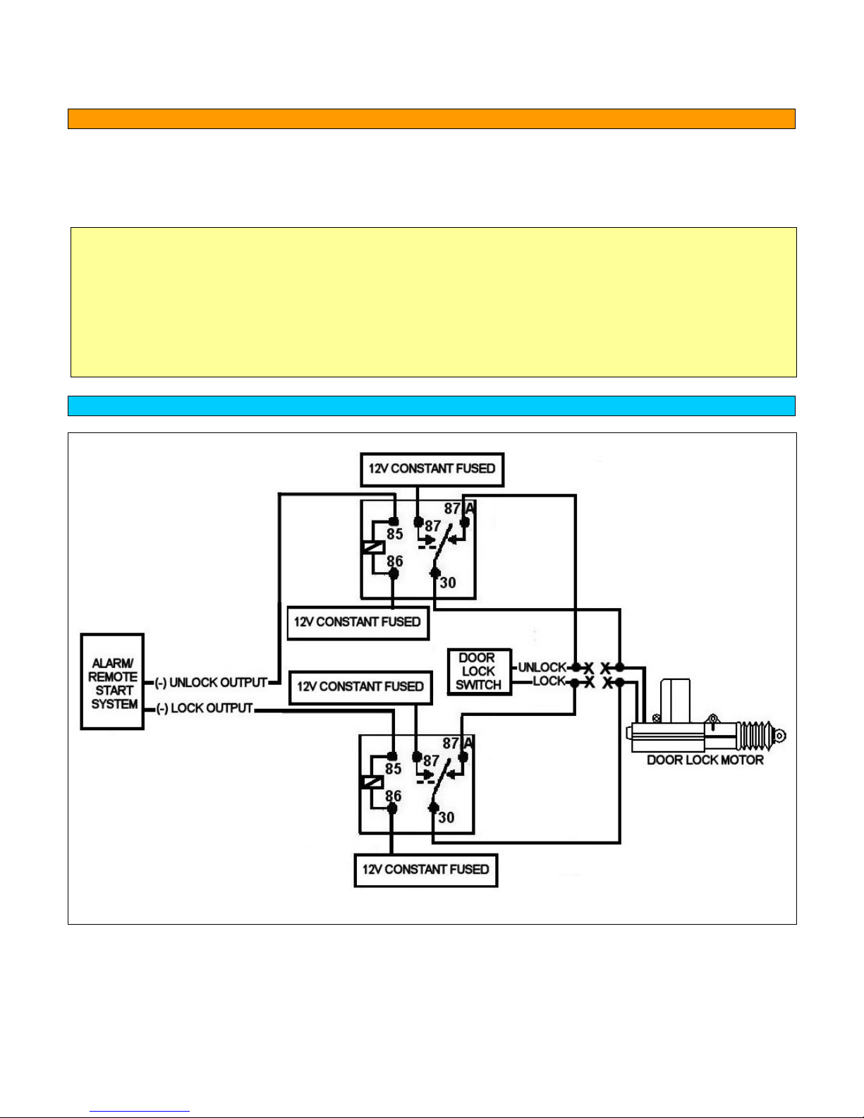
CAR ALARM AND REMOTE START INSTALLATION GUIDE
TESTING REVERSE POLARITY DOOR LOCKS
• Some models use a reverse polarity door lock system. Interfacing with a reversing polarity door lock
system requires two relays. It is critical to identify the proper wires and locate the master switch to
interface properly.
1. Locate a wire that shows 12V on lock and a wire that shows 12V on unlock.
2. Cut one of the suspect wires and check operation of the locks from both switches. If one switch loses
operation in both directions and the other switch operates in one direction only, you have located one of the
target wires.
3. The switch that lost all operation is the master switch.
4. If both switches still operate, but one door has stopped responding entirely, you have cut a motor lead.
Reconnect it and continue to test for another wire.
5. Once both wires have been located and the master switch identified, cut both wires and interface with two
relays as shown below:
WIRING RELAYS FOR REVERSE POLARITY DOOR LOCKS
Use relays to interface with a reverse polarity door lock system as shown:
NOTE: If not connected correctly, the system or factory switch may be damaged.
Copyrght 2002-2004 Triple S Customs 47
Page 48
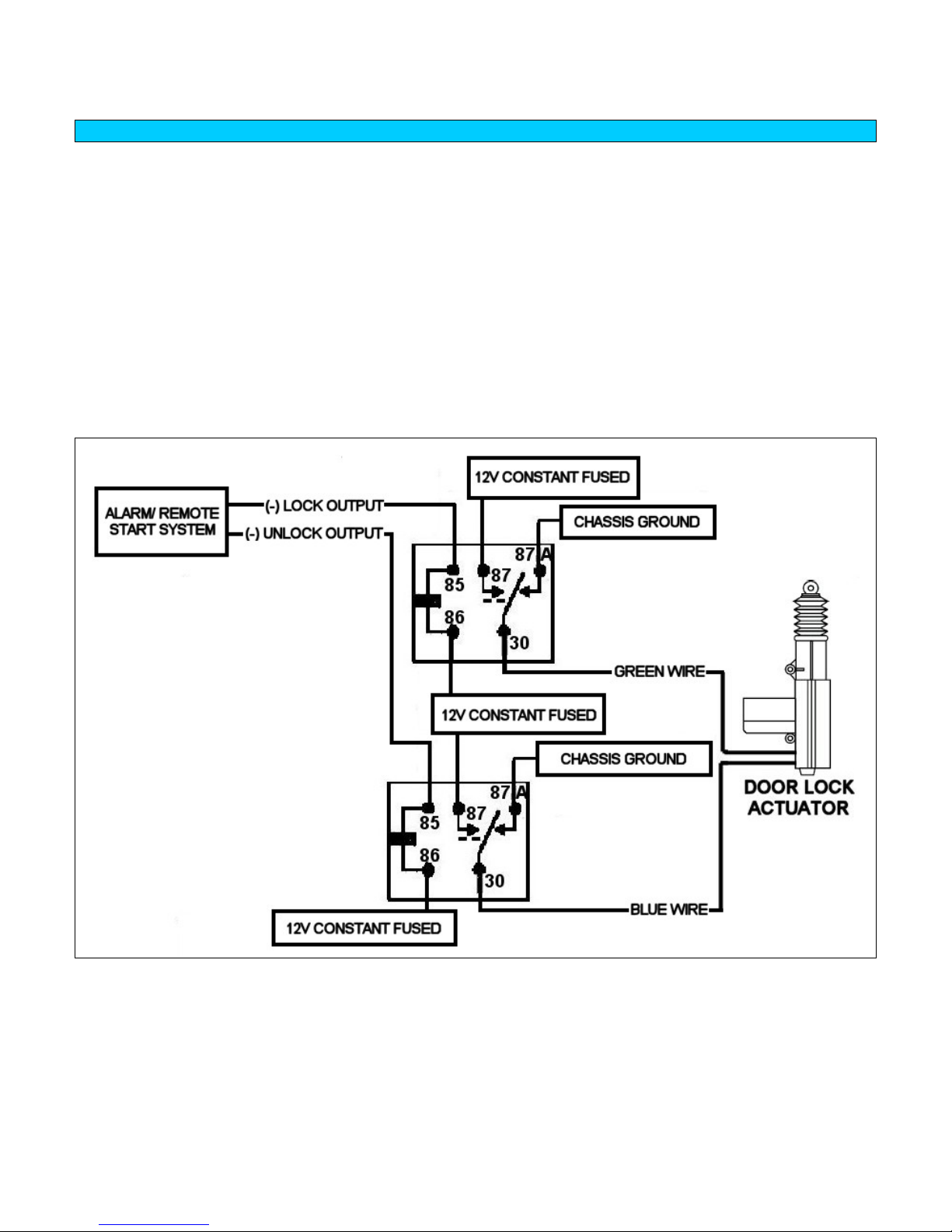
CAR ALARM AND REMOTE START INSTALLATION GUIDE
ADDING DOOR LOCK ACTUATORS
• Vehicles without factory power door locks require the installation of an actuator in each door.
• This requires mounting the door lock actuator inside the door. The fuse used on 12V inputs should be 7.5A
per motor.
• To install door lock actuators the door panel must be removed.
• Most actuators come with mounting instructions. Read and carefully follow all directions.
• Locate the metal rod that moves when the doors are locked or unlocked. Notice how it moves when the locks
are locked and unlocked. The actuator needs to be mounted so that it can pull and push that rod to lock and
unlock the door.
• The actuator should be mounted in a way that it moves parallel to the locking rod of the door.
• The actuator must be mounted so that the door panel can be reinstalled without interfering with movement of
the door lock actuators, windows, or the door handle.
• Some good spots are located towards the rear of the door
• Carefully wrap all wires and run them into the car.
Copyrght 2002-2004 Triple S Customs 48
Page 49
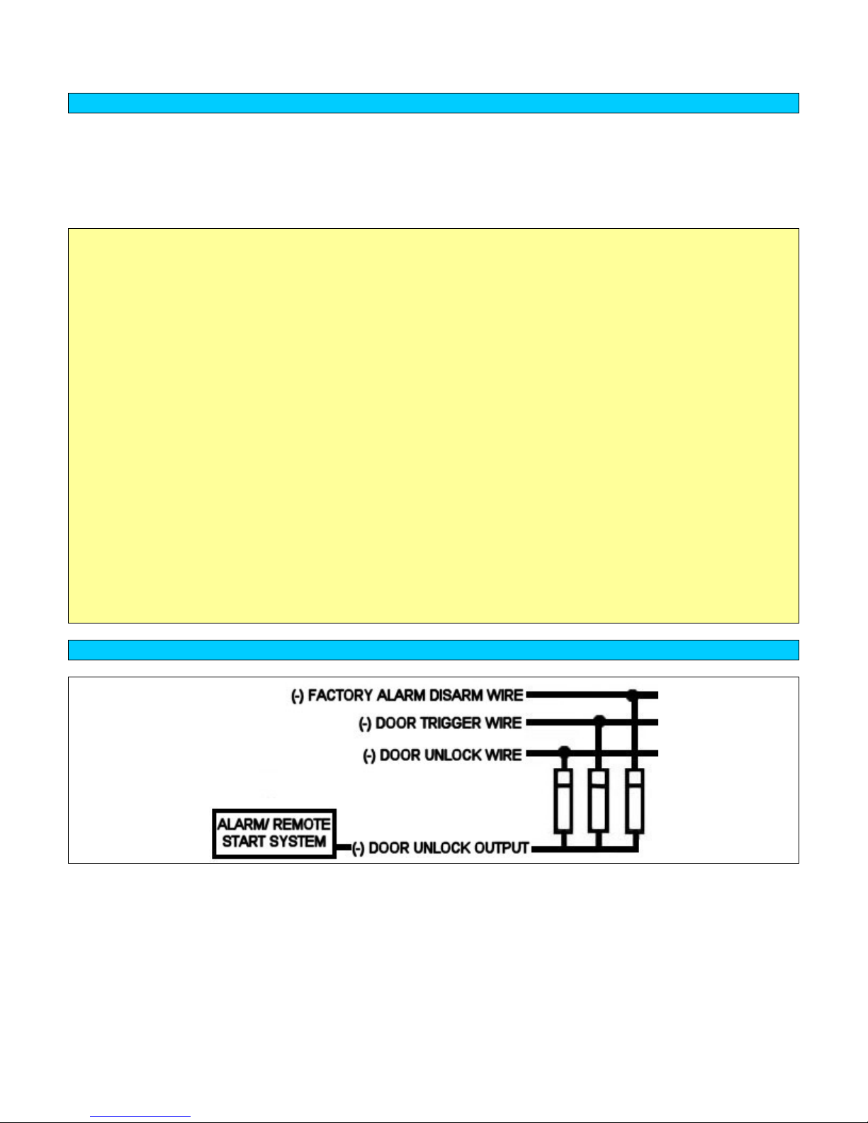
CAR ALARM AND REMOTE START INSTALLATION GUIDE
TESTING THE GEM SHUTDOWN ON 2001-UP MODELS
• For 2001-up models with factory keyless entry, the GEM (General Electronic Module) shuts down a few
minutes after the doors have been locked to conserve battery power. The indication that the GEM is shutting
down will be that the doors will not unlock when the unlocking the doors after the vehicle has been sitting for a
few minutes. The GEM must be awakened in order for the locks to function properly. The GEM will only
awaken if the factory remote is used or a door is opened.
To test the GEM if the factory remote is available
1. With the driver's window rolled down, close all the doors.
2. Lock the doors using the remote control.
3. Wait at least 2 minutes, then reach in through the driver's window and push the unlock switch in the door. If
the doors fail to unlock, then proceed to wire the remote start to wake up the GEM.
To test the GEM if the remote control is not available:
1. Roll down the driver's window and close all doors except for the driver's door.
2. With the driver's door open, manually lock the door by pressing the driver's door lock switch.
3. Close the driver's door.
4. Wait at least 2 minutes, then reach in through the driver's window and press the unlock switch in the door. If
the doors fail to unlock proceed to wire the remote start to wake up the GEM.
To wake up the GEM for a system without a factory alarm
1. Wire the door unlock using wires A and B as shown below. Diode isolate the wires.
2. Program the door unlock output to the double pulse setting.
3. Unlock the system using the alarm system remote. The first pulse to the door ajar and door unlock wire
awakens the GEM; the second pulse unlocks the doors.
To wake up the GEM for a system with a factory alarm
1. Wire the door unlock using wires A and C as shown below. Diode isolate the wires.
2. Program the door unlock output to the double pulse setting.
3. Unlock the system using the alarm system remote. The first pulse to the factory alarm disarm wire awakens
the GEM; the second pulse unlocks the doors.
WIRING DIODES TO WAKE UP THE GEM MODULE
Copyrght 2002-2004 Triple S Customs 49
Page 50
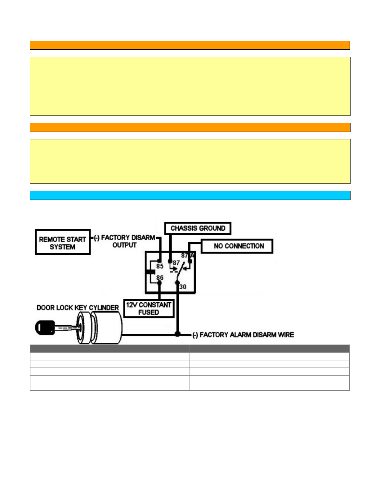
CAR ALARM AND REMOTE START INSTALLATION GUIDE
TESTING TO SEE IF THE VEHICLE IS EQUIPPED WITH A FACTORY ALARM
To test if the vehicle is equipped with a factory security system:
1. Roll down the window on the driver’s door and close all doors of the vehicle.
2. Open the driver’s door and press the door lock switch inside the driver’s door to lock the doors.
3. Close the door. You may notice the “THEFT” light on the instrument cluster stays solid for about 30 seconds
and then begins flashing.
4. Wait 5 minutes, then reach inside the driver’s door and open the driver’s door.
5. If the horn honks, the vehicle is equipped with a factory security system. If the horn does not honk, the vehicle
is not equipped with a factory security system.
TESTING THE FACTORY ALARM DISARM WIRE
To find the factory disarm wire with your multi-meter:
1. Set to DC voltage
2. Attach the (-) probe to chassis ground
3. Probe the wire you suspect of being the factory alarm disarm wire
4. When the switch is at rest, the meter should read 12V
5. Unlock the door with the key. The meter should read 0V or close to it. If it does, that is the correct wire.
WIRING A RELAY FOR FACTORY ALARM DISARM
Use a relay and use the remote start system’s (-) factory disarm wire to disarm the factory security system
as shown:
PIN CONNECTION
85 (-) FACTORY ALARM DISARM OUTPUT
86 12V CONSTANT FUSED
87 CHASSIS GROUND
87A NOT CONNECTED
30 TO (-) FACTORY ALARM DISARM WIRE
Copyrght 2002-2004 Triple S Customs 50
Page 51

CAR ALARM AND REMOTE START INSTALLATION GUIDE
BYPASSING THE PATS ANTI-THEFT SYSTEM
Most new Rangers and B-Series Pickups are equipped with PATS (Passive Anti Theft System). The PATS system
is a transponder based anti theft system. It uses a very small electronic chip (the PATS capsule) hidden in the top
of the key to send a code to the vehicle's transceiver whenever the ignition is energized. For this to happen the key
must be placed in the ignition and turned to the RUN position. This energizes a coil surrounding the key, which in
turn energizes the chip, which sends the signal to the vehicle. If the vehicle does not "see" the code being sent the
car will start and immediately shut off and the anti-theft light in the dash will flash. In order to do a remote start on
a PATS-equipped vehicle, a PATS bypass module MUST be used. Installation instructions may vary depending on
the brand of the bypass module so it's highly recommended to follow the directions included with the bypass
module.
In most cases, a PATS bypass module will be installed this way:
1. Install the remote start and make the proper wire connections to the bypass module. Usually, there is one wire
that is connected to 12V Constant and another wire is hooked up to an output from the remote start that gives
a negative (-) pulse when the vehicle is remote started.
2. Remove the steering column shroud. There should be a plastic ring surrounding the ignition switch. This is the
coil or antenna ring. Connected to the antenna ring through a rubber coated ribbon cable is a small black box.
This is the PATS transceiver. Locate these parts.
3. From the PATS bypass module is a PATS capsule. Attach the PATS capsule to the PATS antenna ring using a
wire tie. Be careful with the placement of the PATS capsule and keep in mind that the steering column shroud
must go back on after installation is successful and complete.
4. With an ignition key, turn the ignition to the RUN position for one second, then turn the ignition off and remove
the key.
NOTE: In some instances it may be required to turn the ignition to the RUN position until the "theft" light in the
dash turns off.
5. With a second key, turn the ignition to the RUN position for one second, and then turn the ignition off. This
must be done within 5 seconds of removing the last key.
NOTE: In some instances it may be required to turn the ignition to the RUN position until the "theft" light in the
dash turns off.
6. Within 10 seconds remote start the vehicle.
7. If the vehicle starts and continues running and the THEFT light in the dash goes out, installing the PATS
capsule has been done successfully. If the vehicle cranks and does not start, and the THEFT light is blinking,
the PATS capsule was not successfully learned. Repeat steps 4-6 again. If the vehicle still does not start, it
may be necessary to relocate the PATS capsule.
NOTE: Placement of the PATS capsule takes some trial and error. Attach the capsule against the outside of the
antenna ring as close to the ribbon cable as possible. Avoid resting the capsule against metal.
Copyrght 2002-2004 Triple S Customs 51
Page 52
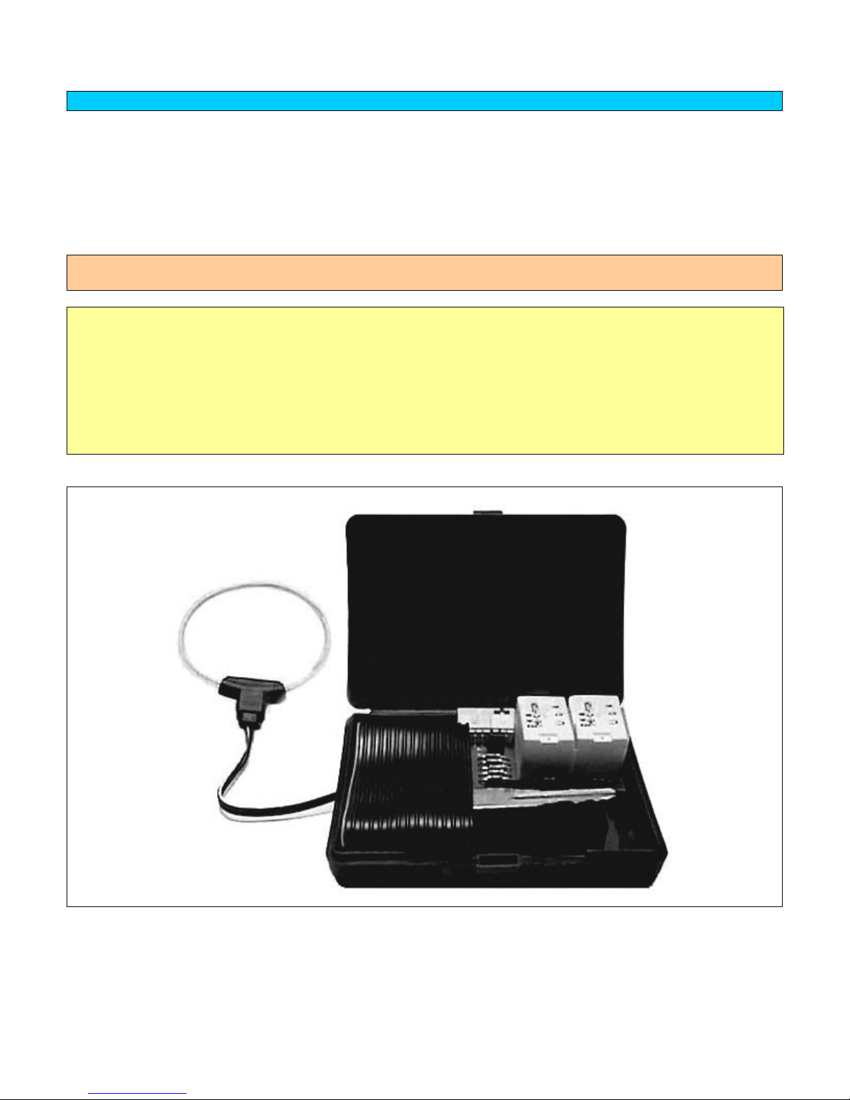
CAR ALARM AND REMOTE START INSTALLATION GUIDE
BYPASSING THE SECURILOCK IMMOBILIZER SYSTEM:
Some models have a factory Immobilizer system. This type of system uses a small chip imbedded in the ignition
key, called a transponder, to transmit a very low powered RF signal. This signal is picked up through an antenna
or coil around the ignition switch, which is then sent to the immobilizer's transceiver. Once the correct signal is
received, the immobilizer will enable the ignition and/or fuel systems. If an attempt is made to start the vehicle and
the transceiver does not receive a valid code, the ignition and sometimes the fuel systems are disable. The
immobilizer system will then render the remote start system useless. The immobilizer system needs to be
bypassed when doing a remote start.
Installation instructions may vary depending on the brand of the bypass module so it's highly recommended to
follow the directions included with the bypass module.
In most cases, an Immobilizer bypass module will be installed this way:
1. Open the module unit and place the vehicle's coded key.
2. Reassemble the unit with the key inside.
3. Carefully disassemble the steering column shroud and place the antenna ring around the ignition switch.
4. The unit will usually have two wires that will need to be connected. One will be connected to 12V constant and
the other will need to be hooked up to a negative (-) output when the vehicle is remote started. This will trigger
the unit when the vehicle is remote started and make the vehicle think the key is in the ignition.
5. Test unit before reassembling the steering column.
6. Reassemble the steering column shroud.
Example of an Immobilizer bypass module:
Copyrght 2002-2004 Triple S Customs 52
Page 53
CAR ALARM AND REMOTE START INSTALLATION GUIDE
WIRES OF AN ALARM AND REMOTE START SYSTEM AND WHAT THEY CONNECT TO:
WIRE FROM SYSTEM WIRE IN VEHICLE TO CONNECT TO
12V+ INPUT (large gauge
wire)
STARTER OUTPUT (large
Connect to high current 12V+ source such as the 12V constant wire in the ignition
harness or the battery
Connect to starter wire at ignition harness
gauge wire)
IGNITION OUTPUT (large
Connect to main ignition wire at ignition harness
gauge wire)
SECOND IGNITION
OUTPUT (large gauge
Connect to second ignition wire at ignition harness. Not all vehicles will have a
second ignition wire.
wire)
ACCESSORY OUTPUT
(large gauge wire)
Connect to main accessory wire at ignition harness. Some vehicles have more than
one accessory wire. If so, each additional accessory wire must be energized with a
relay.
LOCK OUTPUT Usually a low-current output. Connects directly to the lock wire on some vehicles.
Relays or diodes will be required to interface on most vehicles.
UNLOCK OUTPUT Usually a low-current output. Connects directly to the unlock wire on some vehicles.
Relays or diodes will be required to interface on most vehicles.
12V+ INPUT (smaller
gauge wire)
Some systems have an additional 12V+ input wire. This will connect to the 12V+
constant wire in the ignition harness or the battery
IGNITION INPUT Connects to the main ignition wire at the ignition harness
CHASSIS GROUND Connects to the chassis of the vehicle preferably at a factory ground point
SIREN OUTPUT Typically connects to the siren’s RED wire. The BLACK wire from the siren is
connected to chassis ground.
(+) DOOR TRIGGER
Connects to the vehicle’s (+) door trigger wire if the vehicle has a (+) door trigger.
INPUT
(-) DOOR TRIGGER
Connects to the vehicle’s (-) door trigger wire if the vehicle has a (-) door trigger
INPUT
Some vehicles with (-) door trigger wires have a separate door trigger wire for each door. All door triggers must be
located and diode isolated.
DOMELIGHT
SUPERVISION OUTPUT
This will connect to the vehicle’s domelight wire or door trigger wire. Usually
programmable for (+) or (-) door trigger circuits. Check your alarm/remote start
system’s documentation
PARKING LIGHT
OUTPUT
Connects to the vehicle’s parking light wire. Relays or diodes will be required to
interface on some vehicles.
AUXILIARY OUTPUT Can be used to operate a trunk release, fuel door release, power windows or other
features. Relays or other parts may be required.
GROUND WHEN ARMED
OUTPUT
GROUND WHEN
REMOTE START
OUTPUT
Usually used to wire a starter kill relay. Can also be used to provide a negative
trigger for modules that require a signal when the alarm is armed.
Typically connects to modules used to bypass factory security systems when
remote starting the vehicle. May also be used to wire relays for additional starter,
ignition, or accessory wires for remote starting the vehicle.
WAIT-TO-START INPUT On diesel vehicles connects to one of the wires from the wait-to-start bulb in the
dash. May require relays or other parts on some vehicles.
BRAKE INPUT Connects to the vehicle’s brake light wire
TACHOMETER INPUT Connects to the vehicle’s tachometer wire
FACTORY ALARM ARM
OUTPUT
FACTORY ALARM
Connects to the vehicle’s factory alarm arm wire or can be used with a relay to
simulate locking the doors with a door open.
Connects to the vehicle’s factory alarm disarm wire
DISARM OUTPUT
HORN OUTPUT Connects to the vehicle’s horn wire. May require a relay.
Copyrght 2002-2004 Triple S Customs 53
Page 54

CAR ALARM AND REMOTE START INSTALLATION GUIDE
INSTALLING AN ALARM AND REMOTE START SYSTEM WITH KEYLESS ENTRY:
Note: Some steps will not be required when installing a basic alarm system a basic remote start system
or a basic keyless entry system.
1. Begin by carefully disassembling the vehicle. Typically, the dash below the steering wheel, driver’s
running board, and kick panel will need to be removed to access the vehicles wiring. Some vehicles may
require that some of the vehicle’s door panels be removed as well as the running board and kick panel on
the passenger side. When disassembling the vehicle document the disassembly procedure so you know
how to reassemble the vehicle. Place all disassembled parts in a safe place where they will not be
accidentally lost or stepped on.
2. If you haven’t already done so, locate and tag (with wire ties or masking tape) the wires in the
vehicle you will need to connect to. Knowing the exact locations of the wires before you begin installing
the system will help you plan out where you need to route your wiring.
3. Begin installing the system by mounting the system’s control unit. Install the control unit securely in
a safe, dry place inside the vehicle. Never install the control unit under the hood. The control unit should
be mounted in a suitable location that would be difficult for a potential thief to located, but allow for
convenient installation position. Do not mount the control unit in the way of any moving parts. Do not
mount the control unit near any heat sources. Mount the control unit in a way that it does not vibrate or
rattle. Avoid installing the unit anywhere easily visible under the driver's side dash. The first place a thief
will go when attempting to steal a car is the driver's side under dash to access the starter and ignition
wires. If the control unit is easily visible, it can be disconnected and defeated during a theft attempt.
Some good locations are above or behind the glove box, under the center console, above the under dash
fuse box, or in the dash behind the radio. For maximum remote range, mount the control unit high under
the dash and as far away as possible from metal.
4. Route the antenna. The position and location of the antenna will affect remote control range. Do not
shorten or lengthen the antenna. Route the antenna wire away from the control unit. Avoid running the
antenna along any wire harnesses. Keep the antenna and control unit as far away from metal as possible.
If the antenna is intended to be mounted to the windshield, it is recommended that the antenna be placed
behind the rear view mirror or in the upper corner of the passenger side of the windshield with the
antenna pointing down.
5. Mount the LED status indicator. Most alarm and remote start systems have an LED status indicator
used for system programming and diagnostics. It also serves as a theft deterrent. The LED should be
installed in a place visible from both sides and the rear of the vehicle. It is best to install the LED on a
small removable panel like a blank switch or dash bezel. Check for clearance on both sides before any
drilling. Use quick-disconnects near the LED if the panel is removable. This allows the panel to be
removed without having to cut wires
6. Mount the override/ program switch. Alarm and remote start systems have an override switch to
disable the alarm system if the remotes are damaged or missing. The switch is also used for feature
programming. Care must be given to mounting the override switch since just by hotwiring the ignition and
flicking the switch, a thief can disarm the alarm and steal the car. The alarm override switch should be
mounted in someplace hidden but convenient. Good locations include behind the hood release lever,
inside the ashtray opening, inside the center console (where it can't be accidentally bumped), or in the
glove box. Before drilling, check for clearance on both sides.
Copyrght 2002-2004 Triple S Customs 54
Page 55

CAR ALARM AND REMOTE START INSTALLATION GUIDE
7. If the alarm system has an outboard shock sensor (the shock sensor is not “built-in” to the
control unit), secure the shock sensor. Shock or impact sensors are the most common sensors
included with vehicle security systems. They are designed to detect various degrees of impact to the
vehicle during a break-in attempt. Some shock sensors have a dual-stage response. A light shock to the
vehicle may only chirp the siren and/or flash the parking lights to warn away a potential thief or intruder. A
heavy shock will trigger the alarm. These sensors are most effective in detecting a punched-out door lock.
However, when adjusted to be sensitive enough to detect breaking glass, they will false alarm. The shock
sensor should be securely mounted underneath the dash. Use double sided tape or a wire tie to secure it
to an air duct, wire harness, or trim panel. Avoid mounting it in the way of any moving parts or relays.
Avoid mounting it to the steering column or screwing it to metal, as it will cause poor sensitivity
8. Secure the radar, microwave, or field disturbance sensor. Most aftermarket systems do not include
radar sensors but most allow for additional sensors to be added. These sensors are very useful in helping
protect vehicle contents. They flood the area to be protected with a microwave energy field. When the
field is disturbed by a large mass such as a human body, the sensor sends a trigger to the alarm control
unit to trigger the alarm. The larger the object the faster the sensor will react. These sensors are ideal for
protecting convertibles and vehicles with removable tops. Like most shock sensors, these sensors can
also be dual stage sensors. This means they can warn at a distance and trigger to a full alarm if the
interior space is entered. Radar, microwave, and field disturbance sensors generally cover an area similar
to the head of a mushroom. It should be mounted in the center of the interior of the vehicle, facing
upward. If your vehicle has a center console between the front seats, mounting the sensor under this
console facing up may be an ideal location. Make sure that the sensor is not placed behind any metal
parts or major harnesses of the car. The sensor will detect through fabric or plastic, and it needs to face
towards the area that is to be protected. The sensor should always be adjusted outside, away from any
fluorescent lights. These lights, as well as temperature, and weather conditions can affect the sensitivity
of these sensors.
9. After mounting the control unit, shock sensor, and any additional sensors or modules, route the
wires to their intended locations inside the vehicle. In most vehicles you will need to route your wiring
to the ignition harness, the driver’s kick panel, under the hood, the trunk, passenger kick panel, and
sometimes inside one or more of the vehicle’s doors. Plan out what wires need to be routed to each
location and carefully route your wires to that location. Wires should be carefully run from the control unit
to each component. Wires should be wrapped in electrical tape, split loom, or plastic tubing to match the
look of the factory wires. Wires should be run alongside factory wires to make the wires look as if they
came that way from the factory.
10. Running wires from the control module inside the vehicle to the locations under the hood should
be carefully considered. Unlike an amplifier power wire, the wires from an alarm and remote start
system are relatively small gauge, which makes using an existing hole through the firewall a good option.
An alternate method, if an existing hole cannot be found or if thicker wires must be run to provide power
to the alarm and remote start system, is to drill a hole in the firewall. Be certain not to drill through any
fluid lines or factory cables. Use a plastic grommet to protect the wires from being cut by the metal edge
of the drilled holes.
TIPS FOR ROUTING WIRES THROUGH THE FIREWALL:
• Most vehicles have rubber grommets that are large enough to feed your siren wire through using a coat
hanger.
• If the vehicle has an automatic transmission, there is usually a spot reserved for where the clutch cable would
go through the firewall. This is usually an excellent spot to drill a hole.
• Avoid drilling a hole whenever possible. Some vehicles have wires, fuel lines, or brake lines that run inside
the firewall, invisible from either side
Copyrght 2002-2004 Triple S Customs 55
Page 56

CAR ALARM AND REMOTE START INSTALLATION GUIDE
11. Mount the siren. The siren must be mounted securely under the hood. Mount the siren where the siren
cannot be seen or reached from below the vehicle. Mount it away from any heat sources or moving parts
Point the siren down to avoid water collecting in it.
12. Make your connections under the hood. For most alarm and remote start installations you will need to
locate and connect to the vehicle’s tachometer wire and hood pin wire under the hood. Most remote start
systems have a hood trigger input to shut down or disable the remote start when the hood is opened. This
is a safety feature. For a security system, the hood trigger input will trigger the alarm if the hood is
opened. The intent of a hood trigger input is to protect the engine compartment and the contents that are
susceptible to tampering such as the siren, battery, or starter. Generally, models equipped with a factory
security system have a factory hood pin switch. Some vehicles do not have a factory hood pin. In order
to protect the engine compartment a hood pin must be added. Some systems include a pin switch and pin
switch bracket that can be used as a hood pin, or they are available at most car audio and electronics
stores. The pin switch bracket is used to mount the hood pin switch. The bracket is typically and “L”
shape and is mounted to the side of the firewall or inside fender area.
13. Make your connections inside the driver’s door. This will not be necessary on most vehicles, but a
handful of vehicles will require making connections inside one or more of the doors of the vehicle. This
may be required if the door lock wires, door trigger wire, or factory alarm arm or disarm wires are located
only inside one or more of the doors of the vehicle.
14. Make your connections in the driver’s kick panel. This is the area under the driver’s side dash on the
far left side. On many vehicles the door lock wires, door trigger wire, parking light wire, brake wire, factory
alarm disarm wire and/or trunk trigger wire can be found in the driver’s kick panel. These wires may be
found at a module up high in the driver’s kick panel or in the corner against the firewall or they may be
found low in the drivers kick panel in a harness leading towards the rear of the vehicle.
15. Make your connections in the passenger kick panel or behind the glove box. It will not be necessary
to make connections in this location in many vehicles, but on some vehicles wires must be located in a
harness or at a module in the passenger kick panel or behind the glove box.
16. Make your connections in the trunk or rear hatch. It will not be necessary to make connections in this
location on most vehicles, but on a few vehicles the trunk trigger wire or trunk release wire can only be
found in the trunk area.
17. Make your connections at the steering column. This is where you will make all your power
connections and in some cases the horn trigger wire. Take care in working with the ignition harness of
any vehicle. Many other wires, including airbag wires, can usually be found in the ignition harness of most
vehicles. You want to be careful not to accidentally unplug or damage any of the connectors or the wiring.
Unplugging any of the connectors may deploy the airbags or trigger a “check engine” light or similar error
code light to appear on the dash.
18. Connect chassis ground. This is one of the most important connections. A poor or improper ground
causes 90% of all problems that may arise with an alarm or remote start. The best ground point in a
vehicle is a place with a good physical connection to the same metal that the vehicle battery ground itself
shares. Avoid using the bracing underneath the dash. This is a high-resistance ground point and should
not be used. It is preferred that a factory ground point (usually located in the driver’s kick panel) is used.
Some manufacturers in their installation manual recommend and insist on using the negative terminal of
the battery for the alarm or remote start system’s ground point. Connect this wire to bare metal, preferably
with a factory bolt rather than your own screw. Screws tend to either strip or loosen with time. Ground all
components to the same point. If a screw must be used, connect chassis ground to bare metal and use a
star washer to ensure a proper ground connection. Check for clearance on both sides before drilling
Copyrght 2002-2004 Triple S Customs 56
Page 57

CAR ALARM AND REMOTE START INSTALLATION GUIDE
19. Test features and functions. At this point, all your connections should be made and the installation is
complete Program all necessary and desired features for the alarm or remote start system. Consult the
installation manual on how this must be done. If a remote start has been installed, test the vehicle
outdoors in a well ventilated area. Roll down the driver’s window. Put the vehicle in park and set the
emergency brake. Sit inside the vehicle and remote start the vehicle. Turn the climate control system on.
Turn the fan to medium and turn the temperature to hot. Verify the fan is working and there is hot air
coming out of the air vents. Next turn the temperature to cold and turn on the air conditioning and wait to
verify that cold air is coming out of the vents. Verify adequate transmitter range by remote starting the
vehicle from a distance of at least 100 feet. Shut down the vehicle from the same range. Sit in the vehicle
and lock the doors with the remote. Wait 3-5 minutes and remote start the vehicle. If the vehicle’s horn
honks and lights flash, the factory security has been triggered. The remote start will need to be wired to
disarm the factory security. Test the shutdown inputs. The remote start should shut down when the brake
pedal is depressed. Also, most remote start systems have a hood trigger input. This will shut down the
remote start or prevent the remote start from operating if the hood is up. This is a safety feature. If an
alarm has been installed, arm and disarm the system and check that the siren chirps and parking lights
function properly. If power door locks have been integrated, verify the doors lock when the alarm is armed
and unlock when the alarm is disarmed. Test the door inputs. Make sure all doors trigger the system, not
just the driver's door. If the trunk trigger has been interfaced, verify the trunk or rear hatch triggers the
alarm when opened. If a starter disable has been installed, arm the vehicle, wait 30 seconds and try to
start the vehicle. It should not start. If the alarm includes an impact sensor, arm the system, wait 30
seconds and try to trigger the alarm by firmly thumping your fist on the window pillar. Be careful not to
use enough force as to dent the vehicle’s body! Be sure to remove all rings and jewelry first. Adjust
the shock sensor until the desired sensitivity is obtained. Verify the system can be disarmed using the
alarm’s override switch. Consult the alarm’s owner’s manual for the proper procedure. Test any additional
features that have been installed.
20. If all is satisfactory, make sure unit and harnesses are tied up properly and reassemble the
vehicle.
TROUBLESHOOTING
• Remote start will not activate
o Check harnesses and connections. Check power and ground connections.
o Make sure shutdown inputs (brake wire, hood pin) are not active.
• Ignition comes on, but starter does not crank
o Check starter wire connection.
o Check power and ground connections.
o If a starter kill relay is wired make sure the starter wire is connected to the starter side of the relay.
• Starter cranks but does not start
o Check ignition connection.
o Make sure both ignition wires are being energized.
o Make sure system's ignition and accessory wires are not connected backwards.
o Some remote start systems require that the tachometer input wire be programmed before the remote
start will operate properly.
o The vehicle may be equipped with a factory immobilizer system. Try remote starting the vehicle with
the key in the ignition. If the vehicle starts and runs, the vehicle is equipped with an immobilizer. This
will need to be bypassed to remote start the vehicle.
• Climate control system does not work when remote starter is operating
o Check to make sure the correct accessory wire is being energized.
• Starter continues to crank even though engine has started
o Check tachometer wire connection
o Make sure tachometer wire is programmed properly to remote start system
Copyrght 2002-2004 Triple S Customs 57
Page 58

CAR ALARM AND REMOTE START INSTALLATION GUIDE
• CHECK ENGINE light, ABS light, or SERVICE ENGINE SOON light stays after remote starting the vehicle.
o Check that the vehicle’s ignition wires and accessory wires have all been properly interfaced and they
are energized when the remote start is activated
o Check that none of the vehicle’s wiring harness connectors are unplugged
• Factory remotes do not operate when the vehicle is remote started.
o On some vehicles, the factory keyless entry will not operate when the engine is running. This is
normal and cannot be changed.
• System does not respond to remotes.
o Check your power and ground inputs at the system’s control unit.
o Check that all connectors to the alarm/remote start are properly inserted.
o Make sure the system’s antenna is plugged in properly.
o Make sure the remotes are properly programmed and the batteries are new.
• System has poor remote range.
o Most systems provide two remotes. Try using the other remote. The problem may be caused by a
weak remote battery.
o Reposition antenna. Make sure the antenna is extended straight upward and not touching metal.
• Doors lock when they should unlock and unlock when they should lock.
o The door lock outputs from the system are connected backwards.
• Vehicle’s power door lock fuse blows when locking or unlocking the doors using the aftermarket keyless entry
remote.
o Check to be sure you have correctly identified the vehicle’s door lock system and wires for your
vehicle.
o If the vehicle has a reverse-polarity door lock system, the switch side and motor side of the door lock
wires are connected incorrectly.
• Parking lights do not flash.
o Check that the correct parking light wire has been found and interfaced.
• Opening the driver door triggers the alarm but opening any of the passenger doors does not.
o The vehicle has individual door trigger wires. You must find the trigger wire(s) for the passenger
doors.
• Opening the doors triggers the alarm but opening the rear hatch or trunk does not.
o There is a separate trigger wire for the trunk or rear hatch that must be connected to the alarm.
• A short time after arming the alarm, the alarm goes off for no reason.
o You must diode isolate the vehicle’s door trigger wires as described earlier in this document.
o If you have already diode isolated the vehicle’s door trigger wires, check to be sure the diodes are
wired in the proper direction.
• The shock sensor is too sensitive/ not sensitive enough.
o Adjust the sensitivity of the sensor according the manufacturers instructions.
o Try moving or relocating the sensor to a different location.
• Starter disable doesn't work
o Wrong wire has been interrupted.
o Some systems require that the alarm be triggered before the starter disable is active.
• LED doesn't work
o Is it properly plugged in?
• Override switch doesn't work
o Is it properly plugged in?
Copyrght 2002-2004 Triple S Customs 58
Page 59

CAR ALARM AND REMOTE START INSTALLATION GUIDE
o Check the alarm's ignition wire. Make sure it is connected and hooked up to true ignition. True ignition
will show 12V in the run and crank positions of the ignition switch.
• There is a clicking noise coming from the control unit.
o The clicking that you hear is actually from relays inside the control unit. You are hearing the contacts
of the relays opening and closing as the system responds to initial power up or other commands from
the remote or vehicle. This may happen even with the system inactive, and is normal.
GLOSSARY OF TERMS
ACTIVE ARMING: A method of arming a security system that requires the user to physically arm the system by
pressing a button on a remote or entering a code on a keypad.
ARM: The act of causing a security system to reach a state in which it will protect the vehicle.
ARMING DELAY: The elapsed time between the moments a security system is told to arm and the moment it is
actually armed. This normally applies to systems that are passively armed but can also apply to actively armed
systems.
AMPERAGE: Unit of electrical current. Measured in amps.
AUTO RESET: The ability of a security system to automatically reset itself after being triggered.
BACK-UP BATTERY: A separate battery added to the security system as an alternate power supply to serve as
a backup in case the vehicle’s main battery is disabled. Back-up batteries are typically led-acid gel cell types.
These components are most effective when well hidden from detection.
BRAIN: This term refers to the main control unit of a security system or remote start system.
CHANNEL: An output from an alarm or remote start system’s remote that can be used to control a certain
function such as a power trunk release, garage door opener, or power window roll-up.
CHIRP: The brief output from the siren of a security system to indicate if the system has been armed or disarmed.
CONTROL UNIT: The central processor of an alarm or remote start system. Also known as the “brain”.
CURRENT SENSING: The form of a security system trigger input that relies on sensing a change in the power
supply of the vehicle. More accurately called voltage sensing, this feature is found on many inexpensive alarms.
DIODE: A two terminal device that allows a voltage/signal to pass in one direction only.
DISARM: The action of placing a security system in an inactive or standby mode.
DOPPLER SENSOR: Another name for a field disturbance sensor, also known as a radar sensor.
DOMELIGHT: Light mounted in the interior of the vehicle that is turned on when a door is opened. Also called a
courtesy light.
DOMELIGHT SUPERVISION: The ability of a security or remote start system to turn on the vehicle’s dome light
when the alarm is disarmed or when the doors are unlocked. This allows the user to check the interior for an
intruder before entering the vehicle. The light is turned off after a predetermined amount of time or when the
ignition switch is turned on.
EMERGENCY OVERRIDE: Also called valet mode. This allows the vehicle to be disarmed in the case of a lost or
damaged remote or other emergency.
Copyrght 2002-2004 Triple S Customs 59
Page 60

CAR ALARM AND REMOTE START INSTALLATION GUIDE
ENGINE DISABLE: Prevents the engine from starting when the system is armed. The starter, fuel pump, or
ignition may be inhibited.
EVENT MEMORY: A feature with some security systems that informs the car owner of a theft attempt on the
vehicle and which sensor responded to the attempt. This information is given to the user by chirps, LED, and/or
parking lights. Some systems use a prerecorded voice.
FUSE: A device designed to provide protection for a given circuit or device by physically opening the circuit.
Fuses are rated by their amperage and are designed to blow or open when the current being drawn through it
exceeds its rating.
GLASS SENSOR: Detects sound of breaking glass. May pick up sounds of metal on glass and tampering with
windows.
HARNESS: Collection of wires that plugs into the alarm or remote start system and connects to wires in the
vehicle.
IGNITION CONTROLLED DOORLOCKS: Feature included on most alarm and remote start systems that will
locks the doors when the ignition switch is turned on. This is to increase passenger safety.
IMPACT SENSOR: Detects blows and sharp impact to the body of the vehicle. Also known as a shock sensor.
INPUT: Any wire on a security or remote start system designed to accept a signal from some outside source such
as the vehicle’s wiring. Door trigger, hood trigger, trunk trigger, and sensor trigger, and sensor triggers are all
examples of inputs.
LED (Light Emitting Diode): Small light that mounts in car interior and indicates the alarm or remote start’s
status. Flashes to serve as a theft deterrent.
LIGHT FLASH: Sometimes called parking light flash. A feature on alarm and remote start systems that will flash
the vehicle’s parking lights when the system is armed, disarmed, or remote started. May also indicate system
status on some systems.
MULTI-METER: Tool used to measure voltage, resistance, and resistance.
OHM: Unit of measurement for electrical resistance.
OUTPUT: Any wire on a security or remote start system designed to produce a signal intended to be wired to
some outside circuit. Siren wires, parking light flash wires, and door lock wires are all examples of outputs.
OVERRIDE SWITCH: Also called a valet switch. It is a hidden switch used for emergency override or to put the
alarm in a state that will prevent the system from arming. Also used for system programming.
PAGER: A device designed to transmit a signal to the vehicle’s owner to alert the owner that the alarm has been
triggered.
PAIN GENERATOR: Also known as a piezo siren. Small, high frequency siren that sounds in the vehicle’s interior
when the alarm is triggered.
PANIC: Ability to sound the siren or horn to draw attention in case of emergency.
PASSIVE ARMING: Ability of an alarm system to arm automatically after a preset time after the ignition is turned
off and/or all doors are closed.
PINSWITCH: Spring loaded switch that mounts in the door, trunk, or under the hood. Used to complete a circuit
and trigger the alarm if the door, trunk, or hood is opened.
POLARITY: In electricity, refers to the condition of being either positive or negative.
Copyrght 2002-2004 Triple S Customs 60
Page 61

CAR ALARM AND REMOTE START INSTALLATION GUIDE
PROGRAMMABLE FEATURE: The alarm system’s ability to have its features changed to suit the user’s needs.
Some features must be programmed at the time of installation, while others can be made by the owner at will.
RADAR SENSOR: Detects movement within a predetermined area or zone inside or outside the vehicle.
RANGE: Maximum distance from the vehicle at which the remote transmitter will operate.
RELAY: An electromagnetic switch that allows small, relatively low-level signals to operate higher amperage
devices. Also used when polarity-reversal is necessary.
REMOTE: A common name for the remote control unit transmitter used with a remote security or remote start
system.
RESISTOR: A component designed to have a specific resistance.
SENSOR: A device designed to detect or sense an intrusion or attack upon a vehicle by monitoring such things
as motion, vibration, impact, sound, or the presence or a foreign mass.
SIREN: A device designed to produce a loud warning sound when triggered by a security system.
TRIGGER: The common name for any type of stimulus that will cause a security system to produce an alarm. A
trigger can come in the form of a pin switch, sensor, or a direct command from a transmitter or accessory button.
TRUNK RELEASE: The ability of a system to open the trunk/hatch by remote control.
ZONE: The specific area of a security system’s coverage, or a term used to describe a specific trigger input.
Copyrght 2002-2004 Triple S Customs 61
 Loading...