

Page 1
Page 2

TABLE OF CONTENTS
Machine Components
Safety Precautions
Machine Set Up
Machine Operation
Machine Maintenance & Storage
Troubleshooting
Technical Specifications
Parts Lists
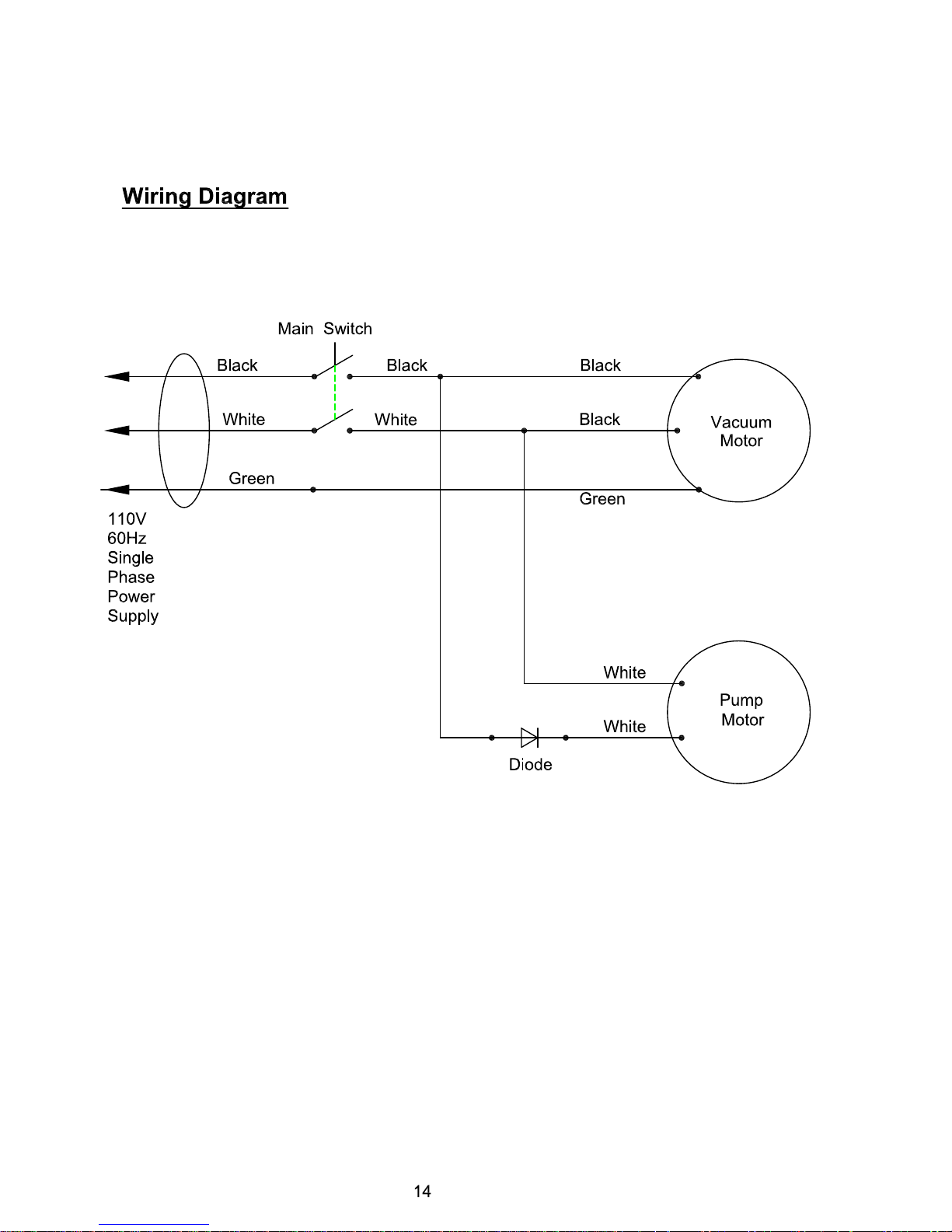
Wiring Diagram
Warranty Policy
1
2
3
3 - 4
5
6
7
8 - 13
14
15
Page 3
Page 4
2
SAFETY PRECAUTIONS
GROUNDING INSTRUCTIONS
General – This carpet spotting machine shall
be grounded while in use to protect the
operator from electric shock. The machine is
provided with a three-contact grounding type
attachment plug to fit the proper grounding
type receptacle. The green (or green & yellow)
conductor in the cord is the grounding wire.
Never connect this wire to other than the
grounding pin of the attachment plug.
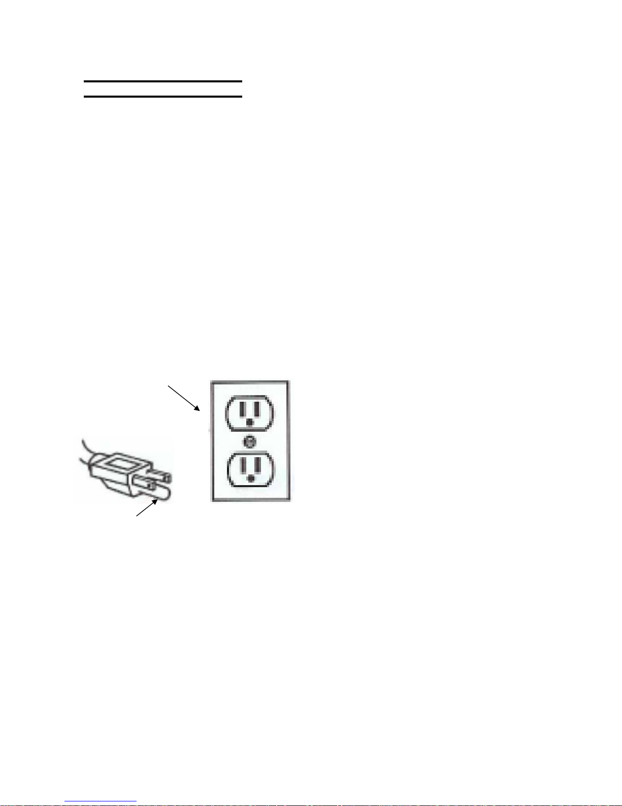
This machine is for use on a nominal 120-volt
circuit and has a grounding plug that
resembles the plug illustrated in figure below.
Make sure that the machine is connected to
an outlet having the same configuration as the
plug. No adapter should be used with this
machine.
Grounded
3 Hole Outlet
Ground Pin
(120V)
This machine is intended for commercial use.
It is constructed for use in an indoor
environment and is not intended for any other
use. Use only recommended accessories.
All operators shall read, understand and
exercise the following safety precautions:
1) Do not operate machine:
- Unless trained and authorized
- Unless you have read and understand
operators manual
- In flammable or explosive areas.
- With damaged or modified cord or plug.
- If not in proper operating condition.
- In outdoor areas.
- In standing water.
- Without filters in place.
- With the use of unapproved extension
cords.
2) Before operating machine:
- Make sure all safety devices are in place
and operate properly.
3) When using machine:
- Mix and handle any chemicals according
to manufacturer’s recommendations
- Do not run machine over cord.
- Do not pull machine by cord or plug.
- Do not pull cord around sharp edges or
corners.
- Do not unplug by pulling on the cord.
- Do not stretch cord.
- Do not handle plug with wet hands.
- Keep cord away from heated surfaces.
- Do not pick up flammable materials or
reactive metals.
- Report machine damage or faulty
operation immediately.
4) Before leaving or servicing machine:
- Turn off machine.
- Unplug power cord from outlet.
5) When servicing machine:
- Unplug cord from outlet.
- Use manufacturer supplied or approved
replacement parts.
- Avoid moving parts. Don’t wear
loose clothing.
Page 5
3
CARPET SPOTTER - SETUP
!!! Read operators manual thoroughly
prior to operating or servicing this
machine!!!
Carefully check the shipping carton for signs
of damage. Report any carton damage to
carrier immediately.
Check carton contents to ensure carton is
complete. Contact your distributor if anything
is missing.
Contents:
z Carpet Spotter
z Vacuum & Solution hoses
z Hand tool
!!! Read operators manual
thoroughly prior to operating or
servicing this machine!!!
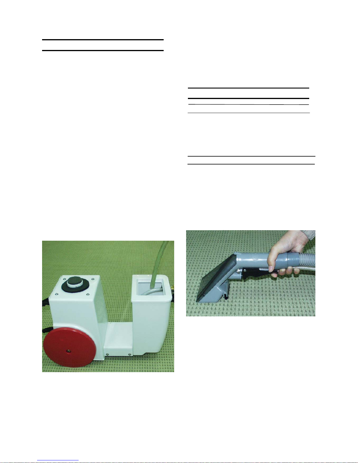
1) Using a hose or bucket, fill tank with a
maximum of 1 gallon of water.
!!! Do not use flammable liquids or
operate machine in or near
flammable liquids or vapors!!!
2) Connect the solution hose and vacuum
hose to the machine.
3) Connect the power cable to a grounded
wall outlet. (see grounding instructions)
MACHINE OPERATION
PRIOR TO REMOVING SPOTS
1) Inspect power cable for damage.
Replace cable if damage is found.
2) Vacuum carpet to remove debris prior to
extracting the spot.
SPOT REMOVAL
1) Turn on vacuum / pump switch.
NOTE: Solution will only spray when the
spray handle(on the hand tool) is pulled.
2) To start cleaning, pull the spray handle
(hand tool) and begin to pull the tool
backwards over the spot.
NOTE: For best cleaning results, use
the built-in agitation brush on the hand
tool to help loosen stain.
3) Release spray handle when you have
reached the end of the spot. Continue to
pull hand tool back for another 4 inches to
pick up excess solution.
4) Continue until spot is removed.
Page 6
4
OPERATING HINTS
1) Use cool water only. Hot water may set a
stain.
2) Use the built-in agitation brush to help free
up stain.
3) Continually check for foam buildup in
recovery tank. Use a distributor
recommended foam control solution.
NOTE: Excessive foam buildup will cause
damage to the vacuum motor.
4) Repeat extraction path on heavily soiled
areas.
5) When recovery of the dirty solution ends, or
the solution tank is empty, you must drain
the recovery tank. (see TANK DRAINING)
DRAINING TANKS
DRAINING SOLUTION TANK
1) Turn machine off and unplug from power
source.
2) Disconnect solution and vacuum hoses
from front of machine.
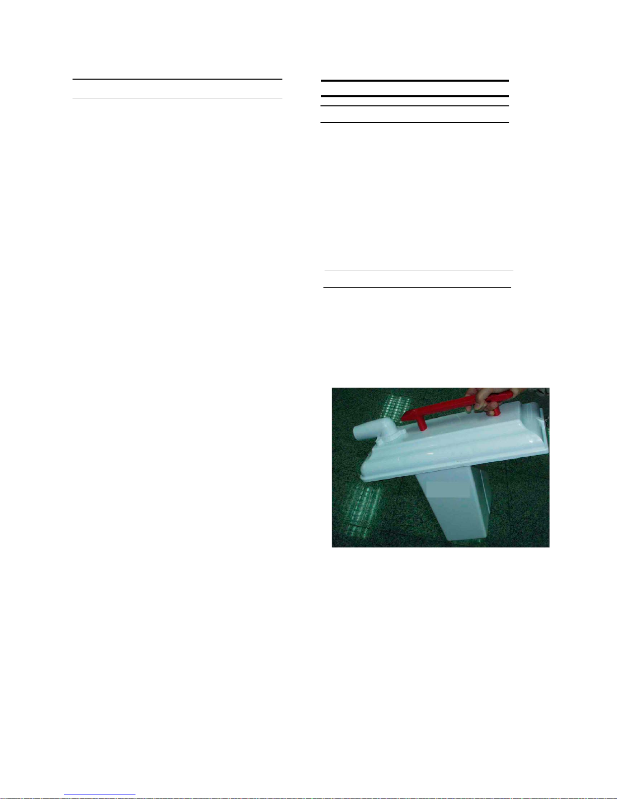
3) Unhook clamps on recovery tank and
remove recovery tank from machine.
4) Carry solution tank to an approved drain,
and dump out contents.
DRAINING RECOVERY TANK
1) Turn off machine and unplug from
power source.
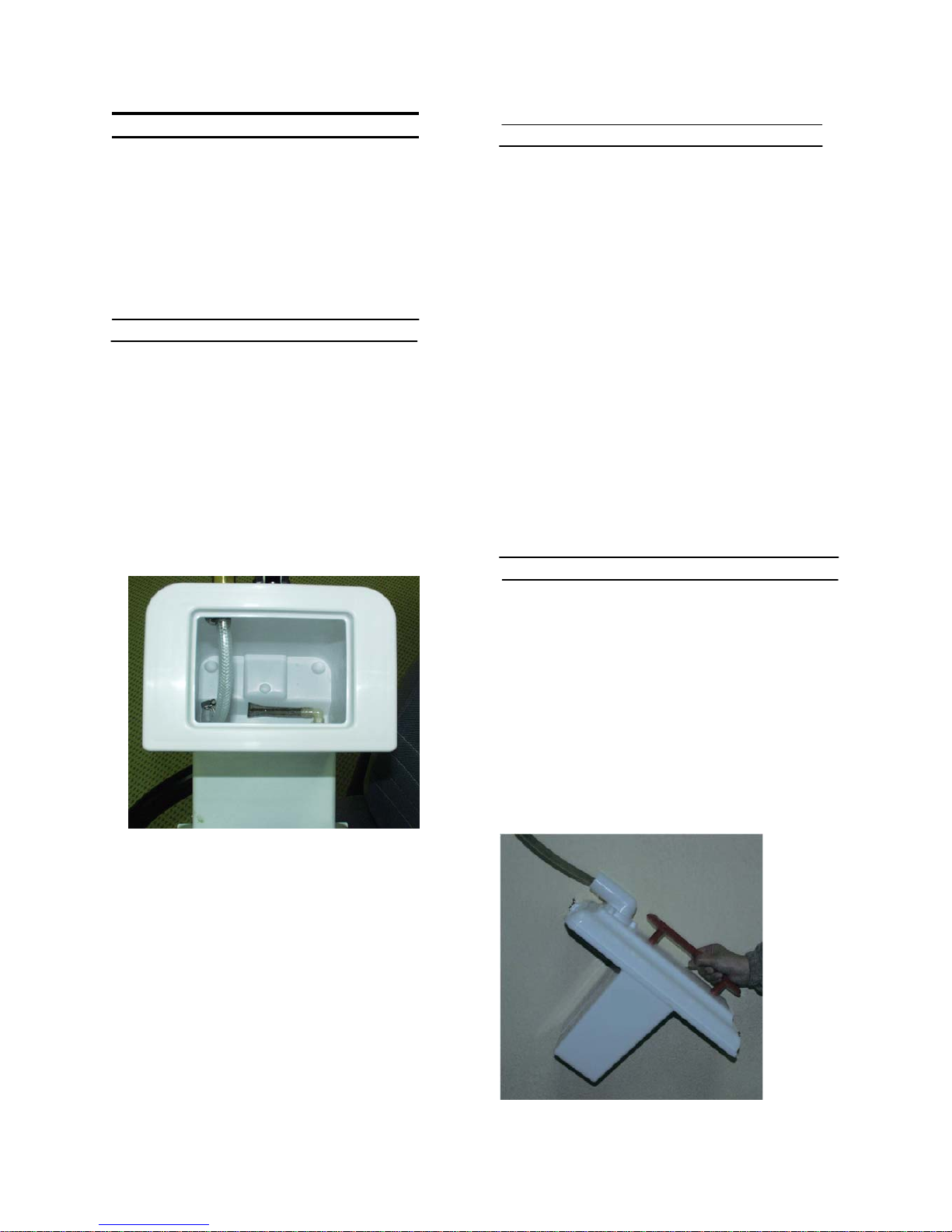
2) Unhook clamps on recovery tank and
remove recovery tank from machine.
3) Carry recovery tank to an approved
drain and dump out contents.
4) Rinse recovery tank with clean water.
5) Reattach recovery tank to the solution
tank.
Page 7
5
MACHINE MAINTENANCE
To keep the machine performing well
for many years, please follow the
following maintenance procedures.
!!! Always confirm that the machine
is unplugged prior to performing
any maintenance or repairs!!!
DAILY MAINTENANCE
1) When cleaning operation is complete
for the day, drain and rinse the
recovery tank thoroughly with clean
water.
2) Remove remaining solution from
solution tank.
3) Remove vacuum filter and rinse with
clean water.
4) Replace filter when dry.
5) Remove and inspect spray jet. If
necessary, clean jet.
NOTE: Do not clean jet with a pointed
object, as it will damage the jets.
6) Check brush strip & remove any debris
or carpet fibers.
7) Check pick up head on hand tool and
remove any debris or carpet fibers.
8) Clean machine with a nonabrasive cleaner.
9) Inspect power cable for any damage.
Replace if necessary.
MONTHLY MAINTENANCE
1) Flush pump & plumbing with an acetic
acid solution to dissolve any chemical
buildup.
Mixing Instructions:
a) Premix 8 oz. of an acetic acid solution
with 1 gallon of water and pour into
solution tank.
b) Turn vacuum / pump switch on
c) Put floor tool head over floor drain
and pull solution trigger for one (1)
minute.
d) Turn machine off and allow
remaining solution to sit in machine
overnight.
e) The following day, spray out
remaining solution and flush system
again with 1 gallon of clean water.
2) Inspect machine for water leaks.
3) Check machine for loose or missing nuts,
screw and bolts and replace as necessary.
MACHINE STORAGE
1) Prior to storing the machine, ensure the
solution and recovery tanks are clean and
empty of any solution.
2) Store machine in upright position in a dry
area, with the vacuum hose removed for
air circulation.
NOTE: If you are storing the machine in an
area which can freeze, be sure both tanks
and the solution plumbing are empty of all
water and dry!
Page 8
6
BASIC TROUBLESHOOTING
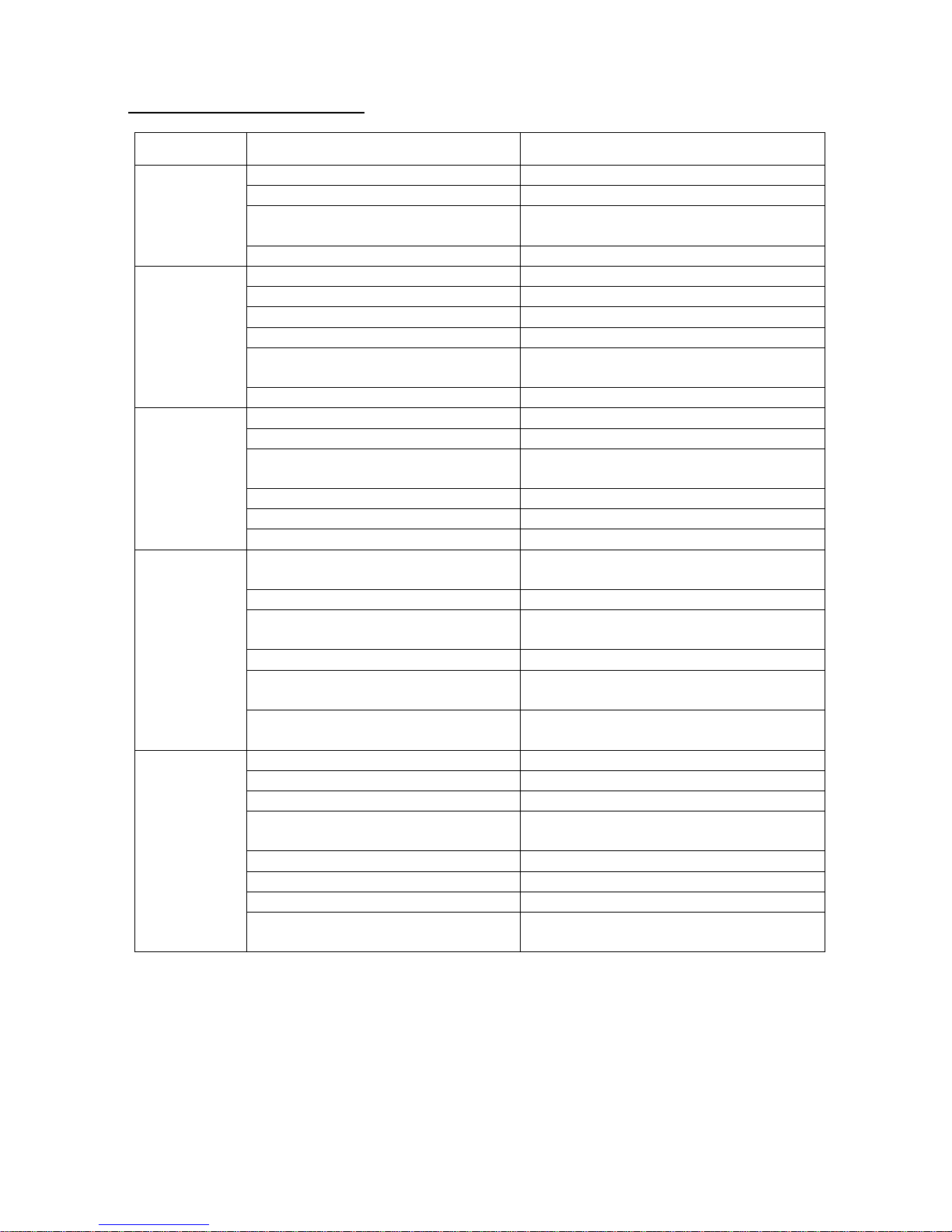
PROBLEM CAUSE SOLUTION
Machine
doesn't work
Not plugged in to power source Plug into a grounded outlet
Faulty power cable Contact Distributor
Faulty extension power cable Replace with new extension power
cable
Building circuit breaker tripped Reset circuit breaker
Solution
pump not
working
Vacuum / pump switch not on Turn on switch
Vacuum / pump switch faulty Contact Distributor
Faulty solenoid Contact Distributor
Faulty solution pump Contact Distributor
Pump overheated
Determine cause and allow 30
minutes for pump to cool
Loose or broken wiring Contact Distributor
Vacuum
motor not
working
Vacuum / pump switch not on Turn on switch
Vacuum / pump switch faulty Contact Distributor
Vacuum motor thermal overload
tripped
Check for obstruction and allow 30
minutes to cool
Faulty vacuum motor Contact Distributor
Worn carbon brushes Contact Distributor
Loose or broken wiring Contact Distributor
Poor pick up
Air leaking around recovery
gasket
Ensure recovery lid is firmly tightened
Vacuum gasket damaged or worn Replace gasket
Loose vacuum hose connections Ensure vacuum hose connections are
tight
Defective vacuum hose Replace vacuum hose
Loose vacuum hose cuffs Ensure cuffs are secure to the
housing
Vacuum hose clogged Remove obstruction from vacuum
hose
Uneven or
no solution
spray
Solution tank is empty or low Fill solution tank
Vacuum / pump switch not on Turn on switch
Dirty or plugged spray tips Clean or replace spray tips
Improper spray tip size or spray
angle
Contact Distributor
Worn spray tips Contact Distributor
Faulty solution pump Contact Distributor
Clogged solution tank filter Clean or replace filter
Pinched or kinked solution hose
Check for obstructions and kinks and
reroute or replace if needed
Page 9
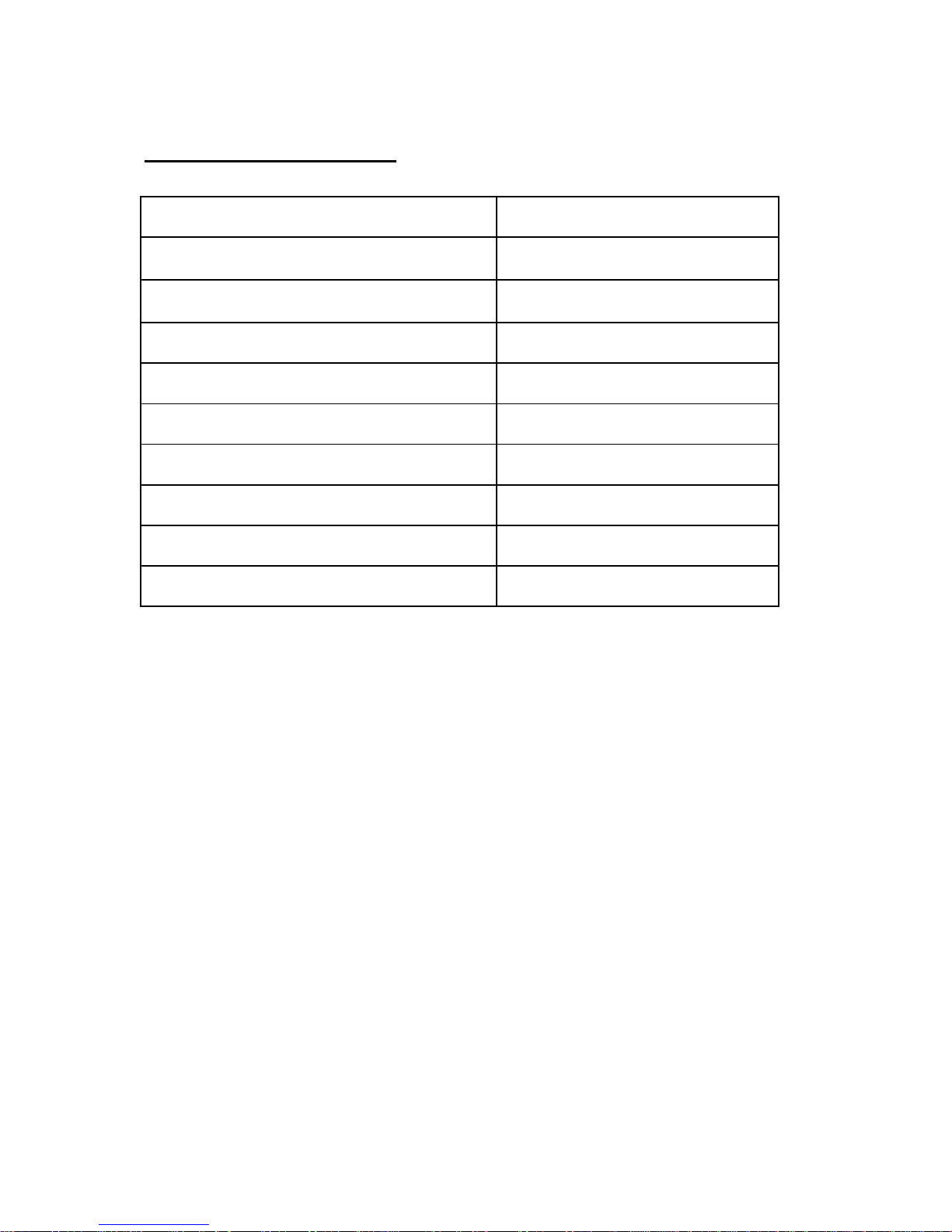
Gallon Capacity 1 Gal (3.79Ltr)
Cleaning Path 4" (10.2cm)
Pump 30PSI
Vac Motor 2-Stage
Voltage 110V
Waterlift 85" (215.9cm)
Cable 25ft.
Wheels 8" (203.2mm)
Vacuum Hose 8.2ft.
Solution Hose 8.5ft.
7
Technical Specifications:
Page 10
Page 11

DIA
NO.
PART
NUMBER
DESCRIPTION
NO.
REQ'D
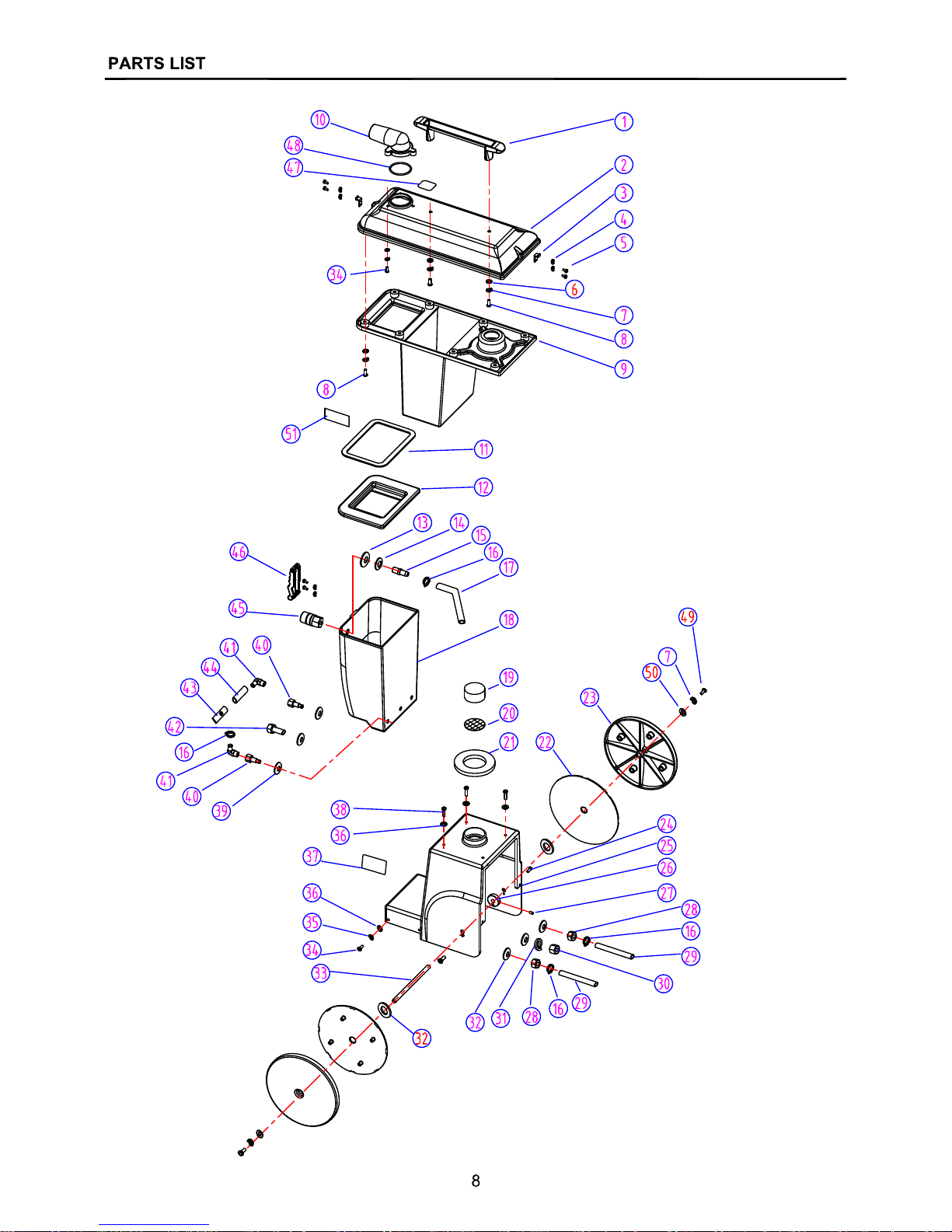
1
VV68104TP HANDLE / CO RD WRAP
1
2
VV68201-2 COVER, RECO V E RY TANK
1
3
VF83109-7 HOOK
2
4
VV20291 WA S HE R, LOCK, M4
6
5
VV13667 SCREW, PH, M4 X 8
6
6
VF13614 WASHER, PLAI N, M6
10
7
VV13607 WA S HE R, LOCK, M6
12
8
VF14200 SCREW, PH, M6 X 16
12
9
VV68201-1 RECOVERY TANK
1
10
VV68201-3 ELBOW, HOSE BARB
1
11
VV68115 GASKET, RECOVERY TANK
1
12
VV68301-2 COVER, SOLUTION T A NK
1
13
VV68130 WASHER, SEAL
1
14
VV20274A WASHER, PLAIN, M14
1
15
VV68135 BARB, HOSE
1
16
VF46400 CLAMP
4
17
VV68141 HOSE
1
18
VV68301-1 SOLUTIO N TANK
1
19
VV68113 FILTER, V A C M OTOR
1
20
VV68114 SCREEN
1
21
VV68111 GASKET, SOLUTI O N T A NK, 4"
1
22
VV68127TP COVER
2
23
VV68105TP WHE E L, 8"
2
24
VF14301 SCREW, M4 X 12
2
25
VV68101 HOUSING
1
26
VV68119 COLLAR
2
27
VF13525 SCREW, M6 X 8
2
28
VV13665 NUT, M10 X 1
2
29
VV68143 HOSE
2
30
VF14005 NUT, M10
1
31
VF13518 WASHER, LOCK, M10
1
32
VF13537 WASHER, PLAIN,M10
5
33
VV68118 AXLE
1
34
VV20501 SCREW, PH, M5 X 14
7
35
VV13601 WA S HE R, LOCK, M5
7
36
VV13662 WASHER, PLAIN, M5
7
37
VV68133TP DECAL, SERIA L
1
38
VV13635 SCREW, PH, M5 X 20
4
39
VV68132 WASHER, SEAL
3
40
VV68128 HOSE BARB
2
41
RD60128 ELBOW, HOS E B A RB
2
42
VF13634 BOLT, M10 x 30
1
43
RD10461 SCREEN
1
44
VV68142 HOSE
1
45
VV80208 COUPLE R, QUICK CONNECT
1
46
VF83109 CATCH
1
47
VV68308 LABEL, DRAINING
1
48
VV68145 SEALER
1
49
VV60220S1 SCREW,M6 X 16
2
50
VF13533 WASHER, PLAI N, M6
2
51
VV68136TR LOGO
2
9
Page 12
Page 13
DIA
NO.
PART
NUMBER
DESCRIPTION
NO.
REQ'D
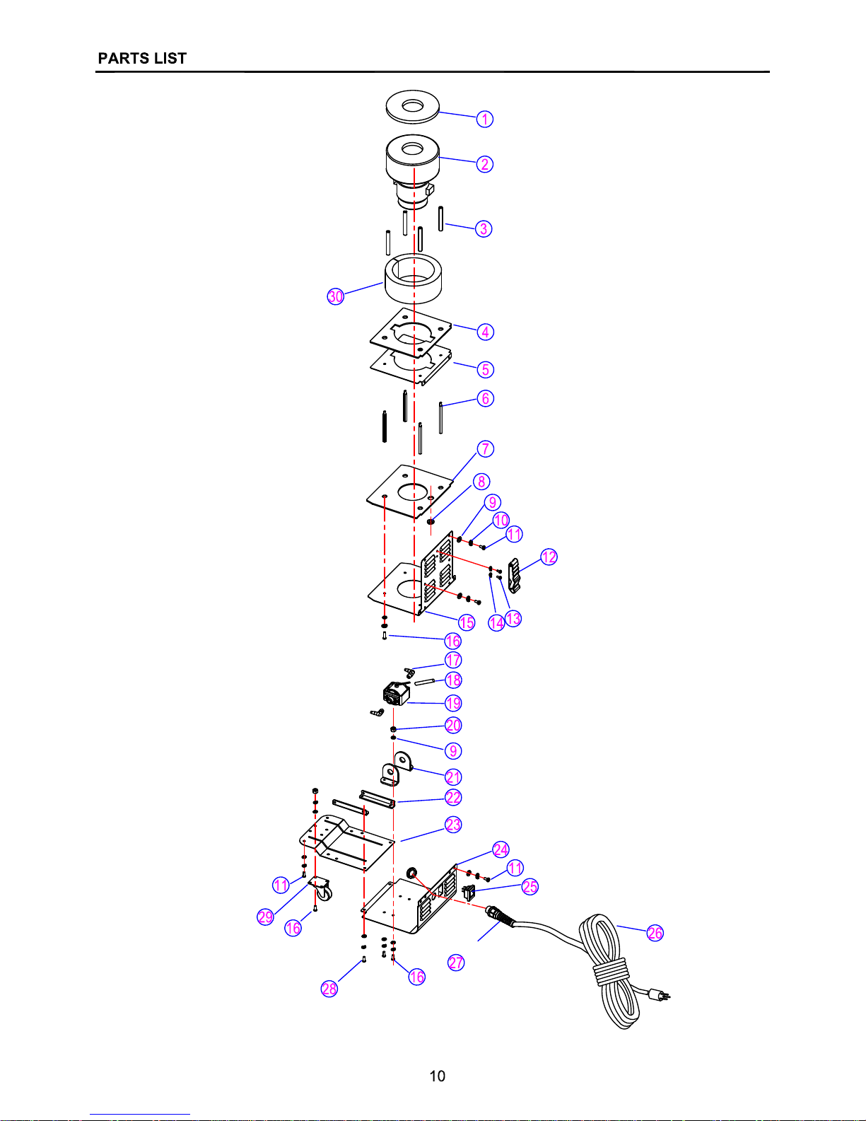
1 VV68112 GASKET, VAC MO TOR, 5.75"
1
2 ZD49000A VACUUM MOTOR, 110V
1
3 VV68116 SPACER, VAC MOTOR
4
4 VV68110 GASKET, VAC MO T O R
1
5 VV68109 MOUNTI NG PLATE, VAC MOTOR
1
6 VV68117 SPACER, VAC PLATFORM
4
7 VV68120 GASKET, BAFFLE
1
8 YQ60504 RING
1
9 VV13662 WA S HE R, PLAIN, M5
32
10 VV13601 WA S HE R, LOCK, M5
28
11 VF14214 SCREW, PH, M5 X 8
12
12 VF83109 CATCH
1
13 VF13666 SCREW, PH, M4 X 6
2
14 VV20291 WA S HE R, LOCK, M4
2
15 VV68107 BAF FLE & REAR PANEL
1
16 VV20501 SCREW, PH, M5 X 14
16
17 RD60128 BARB, HOSE
2
18 RD50258 DIODE ASSEMBLY
1
19 RD50264 PUMP, 110V
1
20 VV13633 NUT, M5
8
21 VV68126 BRACKE T, PUMP MOUNTING
2
22 VV68108-2 CONNECTOR
2
23 VV68108-1 BOTTOM MOUNT PLATE
1
24 VV68106 MOUNTING PLATE, SW I T CH ASSEMBLY
1
25 VA91346 SWITCH ASSEMBLY
1
26 VV30183 POWER CORD
1
27 VF99008B CO RD S TRAIN RELIEF
1
28 VV20509 PH SCREW, M5X10
4
29 VV68123 CASTER, 1.5"
1
30 VV68183 SPONGE
1
11
Page 14
Page 15
DIA
NO.
PART
NUMBER
DESCRIPTION
NO.
REQ'D
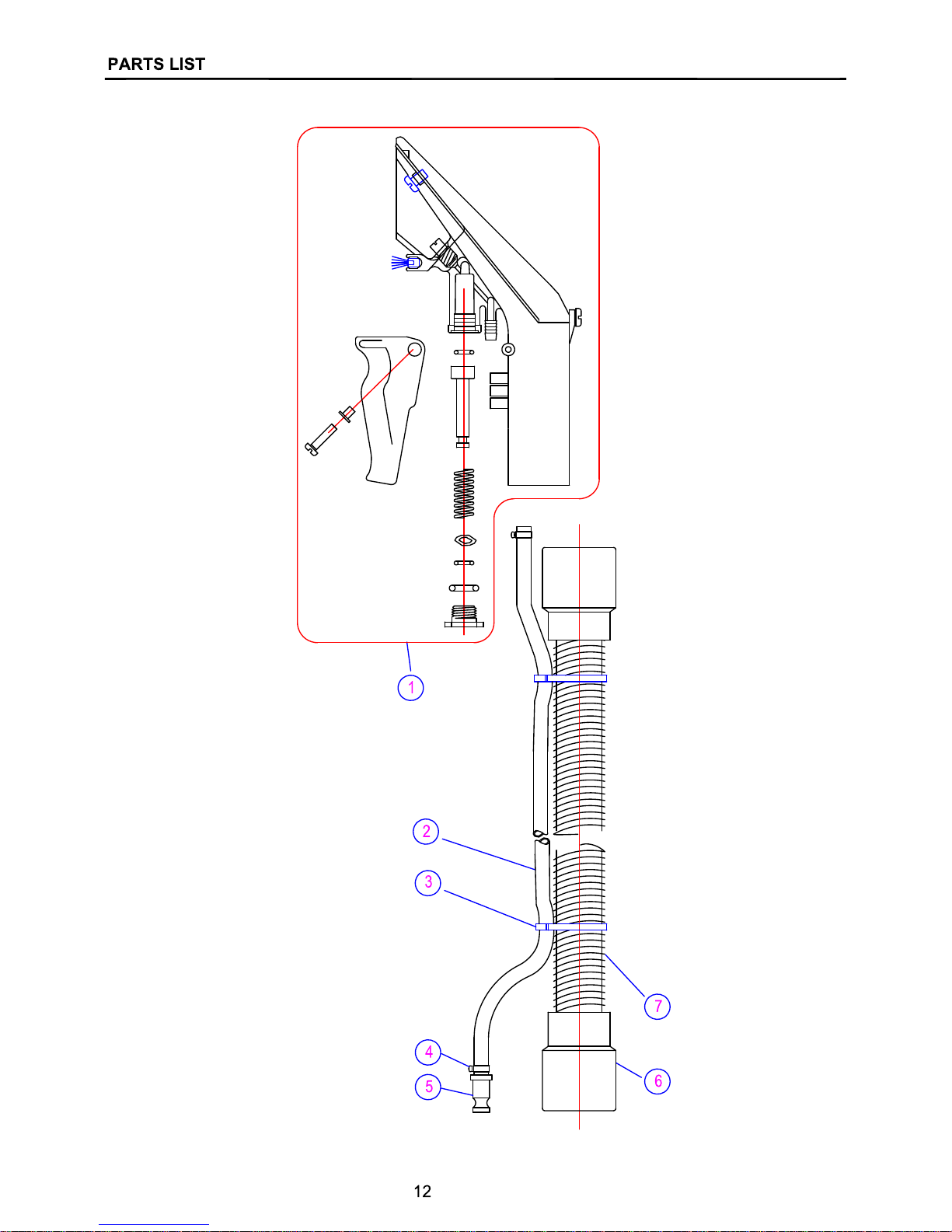
1 ******* HAND TOOL
1
2 VV68148 SOLUTI ON HOSE
1
3 RD20652 CABLE TIE
8
4 RD11177 CLAM P , HOSE
2
5 RD80784 COUPLER, MALE END
1
6 RD60388 HOS E E ND
2
7 VV68147 HOSE
1
******* Contact distr ibutor
13
Page 16
Page 17

WARRANTY POLICY
The warranty terms outlined below are in lieu of any other warranties, either stated or
implied, including any implied warranty of merchantability, fitness for a particular
purpose or otherwise. Under no circumstances will seller be liable for any loss,
damage, expense or consequential damages arising in connection with the use or
inability to use this product.
This warranty does not apply to damage or defect caused by accident, misuse,
negligence, abuse, fire or to any Triple S product which has been serviced by anyone
other than a Triple S authorized service representative. Housings or parts that have
become damaged as a result of improper use of the machine are excluded from this
warranty. Refer to owner’s manual for proper machine u
se and maintenance. Parts
that are expected to wear from normal use and, therefore are not covered under the
parts warranty include, but are not limited to: batteries (pro-
rated for one year);
bearings; belts; brushes; filters; squeegees; switches; and tires.
This warranty commences on the date of purchase of the product by the original end
user from an authorized Triple S distributor, subject to proof of purchase. If proof of
purchase date is unavailable, the warranty begins 90 days after the sale of the
product to an authorized Triple S distributor.
Subject to the conditions outlined above, the manufacturer warrants the
rotationally-molded polyethylene housings and parts on its machines to be
free from defects in material
s and workmanship, under normal use and
service for twelve (12) years to the original purchaser.
Under this warranty, the manufacturer guarantees the performance of
non-polyethylene parts and components on Triple S machines to be free
from defects for up to five (5) years to the original end user. Parts replaced
under this warranty are guaranteed for the remainder of the original
warranty period.
Labor charges are covered for two (2) full years from the date of purchase
for Triple S products, provided an authorized Triple S service provider is
used for repair. No travel coverage is extended for cord electric machines.
Product Exceptions & Exclusions:. Battery chargers and all accessories are
warranted for one year.
Triple S reserves the right to change the warranty policy without notice.
15
 Loading...