

Ace 20BA Auto Scrubber
The contents of this manual are based on the
latest product information available at the time
of publication. Triple S reserves the right to
make changes or improvements to its
machines without notice.
For new manuals write to:
Triple S
2 Executive Park Drive
Billerica, MA 01862
or download the most recent version of the
manuals from our website:
www.triple-s.com
Carefully inspect all components to ensure that
there is no concealed freight damage. If such
damage is discovered, file a “CONCEALED
DAMAGE REPORT” immediately with the
delivering carrier.
FOR YOUR CONVENIENCE, RECORD THE
FOLLOWING IMPORTANT INFORMATION:
SERIAL NUMBER
DATE PURCHASED
Page 1 of 38

SAFETY INSTRUCTIONS
1) You must have training in the operation of the machine before using it. READ THE
INSTRUCTION BOOK. If you do not understand any instruction, ask your supervisor.
2) Make sure all labels, decals, warnings, cautions and instructions are fastened to the
machine.
3) Read the labels carefully on the machine. Do not cover them for any reason and replace
them if damaged.
4) Do not operate this machine unless it is completely assembled and inspect the machine
carefully before operation.
5) Pay close attention to other people and especially children while operating this machine.
6) Be a careful driver and do not strike shelving or scaffolding, especially where there is a
danger of falling objects.
7) Machines can cause an explosion when operated near flammable materials and vapors.
Do not use this machine with or near fuels, grain dust, solvents, thinners, or other
flammable materials.
8) In case of fire, use a powder extinguisher. Do not use water.
9) Do not use this machine as a means of transport.
10) Do not use acid solutions that could damage the machine or flooring.
11) Adjust your speed to the conditions of the floor.
12) Do not turn the machine on an incline. Do not stop and leave the machine on a ramp or
incline.
13) During any maintenance operation disconnect the power supply from the machine.
14) Lead acid batteries generate gases that can cause an explosion. Read the instruction
manual supplied with the battery charger. Keep sparks and flames away from batteries.
NO SMOKING. Charge the batteries only in an area with good ventilation.
15) Do not use a charger if the power cord is damaged or a charger that is not matched to the
machine.
16) Always wear eye protection and protective clothing when working near batteries. Remove
all jewelry. Do not put tools or other metal across the battery terminals, or on the top of the
batteries.
17) Maintenance and repairs must be performed by authorized Service Centers only.
18) Keep the electrical parts of the machine dry. Do not wash the machine with direct water
jets or high pressure, or with corrosive material. For storage, keep the machine in a dry
location.
19) Water solutions or cleaning materials used with this type of machine can leave wet areas
on the floor surface. These areas can cause a dangerous condition for the operator or
other persons. Always put CAUTION signs near the area you are cleaning.
20) Do not reach under shrouds with fingers, hands, or toes when machine is running.
Page 2 of 38
SYMBOLS USED ON THE AUTOMATIC SCRUBBER
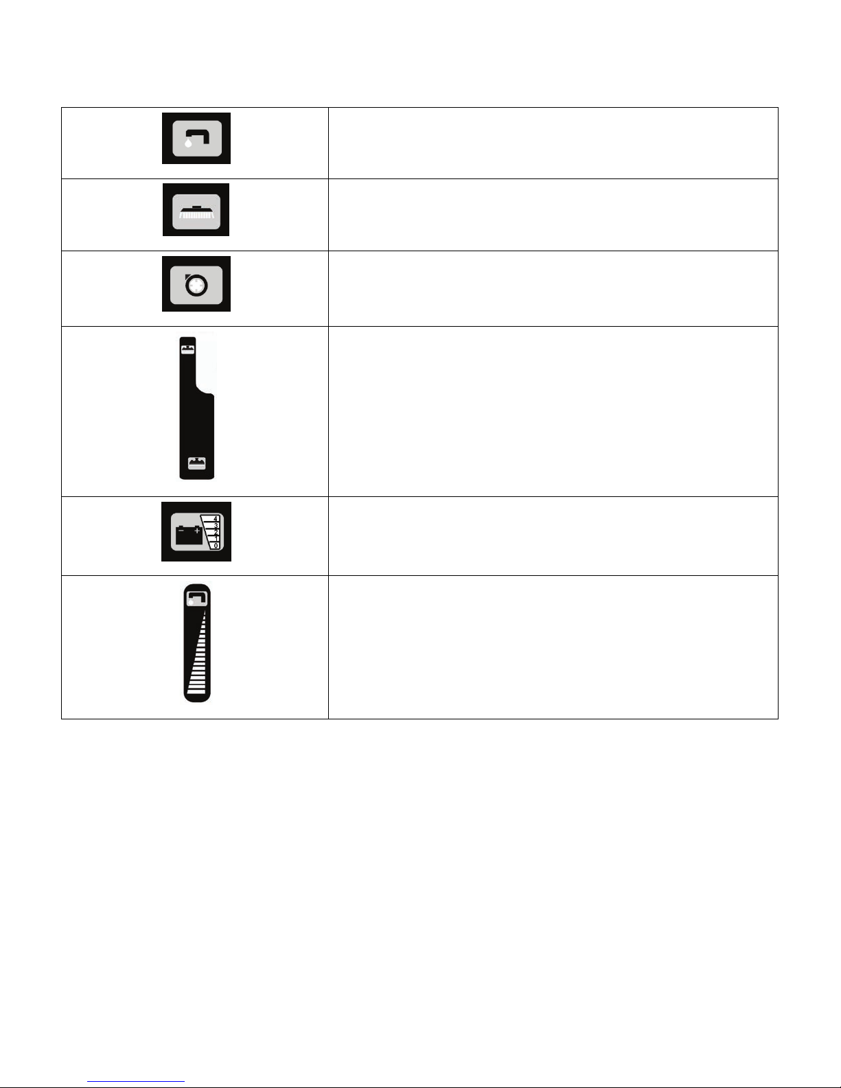
Water Valve Indicator
Brush Drive Motor Control Switch
Vacuum Motor Control Switch
Squeegee Lift Lever Indicator
Battery Charge Indicator
Water Flow Control Indicator
Page 3 of 38
MACHINE PREPARATION
1) UNPACKING THE MACHINE
a) Take off the outer
packaging.
b) The machine is fastened to
the pallet with wooden
wedges that block the
wheels. Remove tie down
straps.
c) Using a ramp, pull the
machine off the pallet.
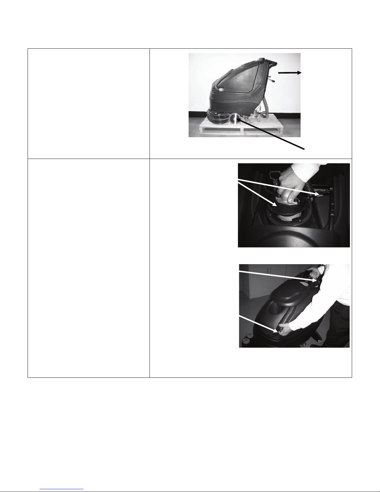
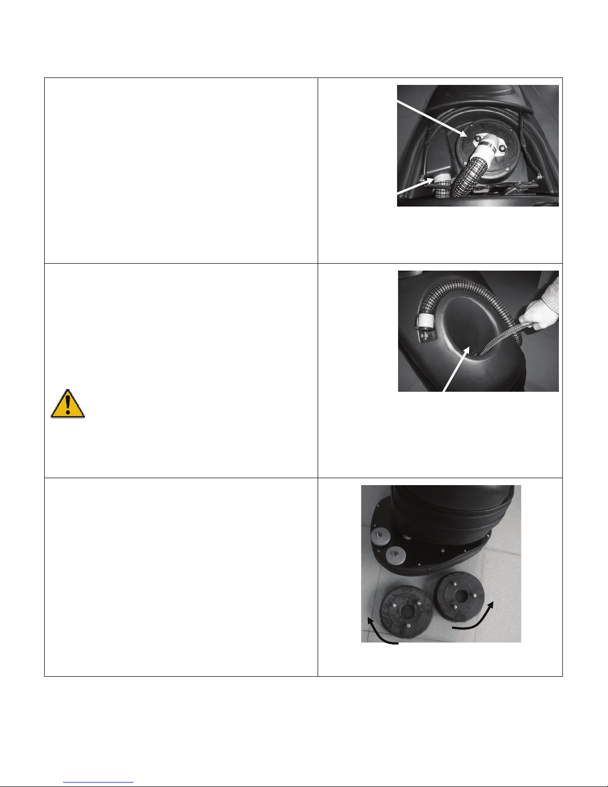
2) BATTERY INSTALLATION
a) Remove the squeegee hose
from the recovery tank.
b) Remove the vacuum cover
by rotating it
counterclockwise.
c) Remove recovery tank by
lifting tank by lift chain at the
back of the tank and the
drain hose at the front of the
tank.
Remove
Lift Chain
Drain Hose Lift Point
Pull
Backwards
Remove
Page 4 of 38
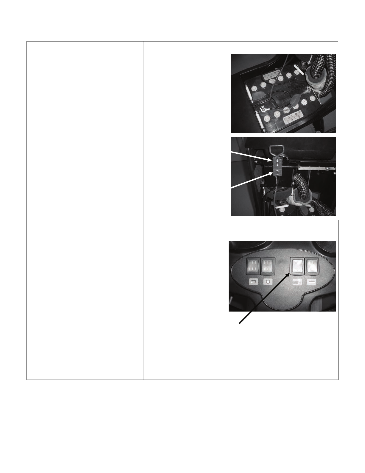
BATTERY INSTALLATION
(Cont.)
d) Place the batteries in the
battery compartment.
e) Connect the battery
connector to the machine
connector
f) Replace the recovery tank
and reassemble the vacuum
cover and squeegee hose.
MACHINE PREPARATION
Machine Connector
Battery Connector
3) BATTERY CHARGE LEVEL
INDICATOR
The battery indicator is digital with
4 display levels and a flashing one.
The numbers, which appear on the
display, show the approximate
charge level. 4 represents a full
charge and 0 represents
discharged and the batteries must
be recharged.
NOTE: The brush motor
automatically switches off after
the battery indicator light
begins to flash. You will be
able run the vacuum motor and
finish drying any wet areas.
Battery Charge
Indicator
Page 5 of 38
MACHINE PREPARATION
4) SQUEEGEE ASSEMBLY INSTALLATION
The squeegee is assembled to the machine
by lifting the locking latches and sliding the
squeegee assembly onto the 2 posts at the
rear of the squeegee swing arm. Push on the
locking latches down. Lower the squeegee
and install vacuum hose over vacuum outlet
on squeegee assembly. The hose should be
located to the rear of the lifting cable.
5) ADJUSTING SQUEEGEE HEIGHT
The height from floor to squeegee should be
adjusted based on blade wear. Rotate the
adjusting knobs counter-clockwise to lower
squeegee and clockwise to lift it.
NOTE: Rotate the right and left adjusting
knobs until the squeegee is positioned parallel
to the floor.
Vacuum
Outlet
Locking Latches
Height
Adjusting
Knobs
6) ADJUSTING SQUEEGEE INCLINATION
During operation the rear squeegee blade is
most efficient when bent backwards roughly
3/16
ths
to 5/16
ths
of an inch along its entire
length. To increase the blade bending in the
center of the squeegee, tilt the squeegee body
backward by turning the adjuster knob
counter-clockwise. Conversely, turn the
adjuster knob clockwise to increase the
bending at the outside edges of squeegee
blade.
Inclination
Adjusting
Knob
Page 6 of 38
r
MACHINE PREPARATION
7) RECOVERY TANK
Open the lid and confirm the following
connections are secure:
a) The vacuum cover is securely attached.
Align the notches and rotate the cover
clockwise to close. The vacuum hose
must also be attached.
b) Confirm that the squeegee hose is properly
connected.
c) Confirm that the drain hose plug, which is
located at the front of the machine, is
closed.
8) SOLUTION WATER
Fill the solution tank with clean water at a
temperature not higher than 50°C / 122°F. Add
the proper concentration of liquid detergent by
following the manufacturer instructions. Excess
foam in the recovery tank can damage the
vacuum motor, so use only the minimum amount
of detergent necessary. Reassemble the cover.
WARNING! Always use low foaming
detergent. Adding antifoam liquid into
the recovery tank before cleaning will also help
prevent foaming.
NEVER USE ACID, BLEACH or AMMONIA
Vacuum
Cove
Squeegee
Hose
Solution Tank
Fill Opening
9) BRUSH INSTALLATION
a) Lift the brush base by depressing the foot
level at the rear of the machine.
b) Place the brushes under the base. Align
the brush lugs with the holes in the brush
plate. Insert the brushes into the plate and
turn each brush so the lugs are pushed
toward their retaining springs, until locked.
The photo shows the directions to rotate
the brushes to lock them into operating
position.
Page 7 of 38

MACHINE PREPARATION
10) SPLASH GUARD INSTALLATION
a) Wrap splash guard around the brush deck
base.
b) Place band clamp over the front band
clamp stud.
c) Pull band clamp around brush deck base
and place band clamp spring over rear
band clamp stud.
d) Repeat process on opposite side of brush
deck base.
Splash
Guard
Front Band Clamp
Stud
Rear Band
Clamp Stud
Band Clamp Spring
Page 8 of 38
r
r
r
r
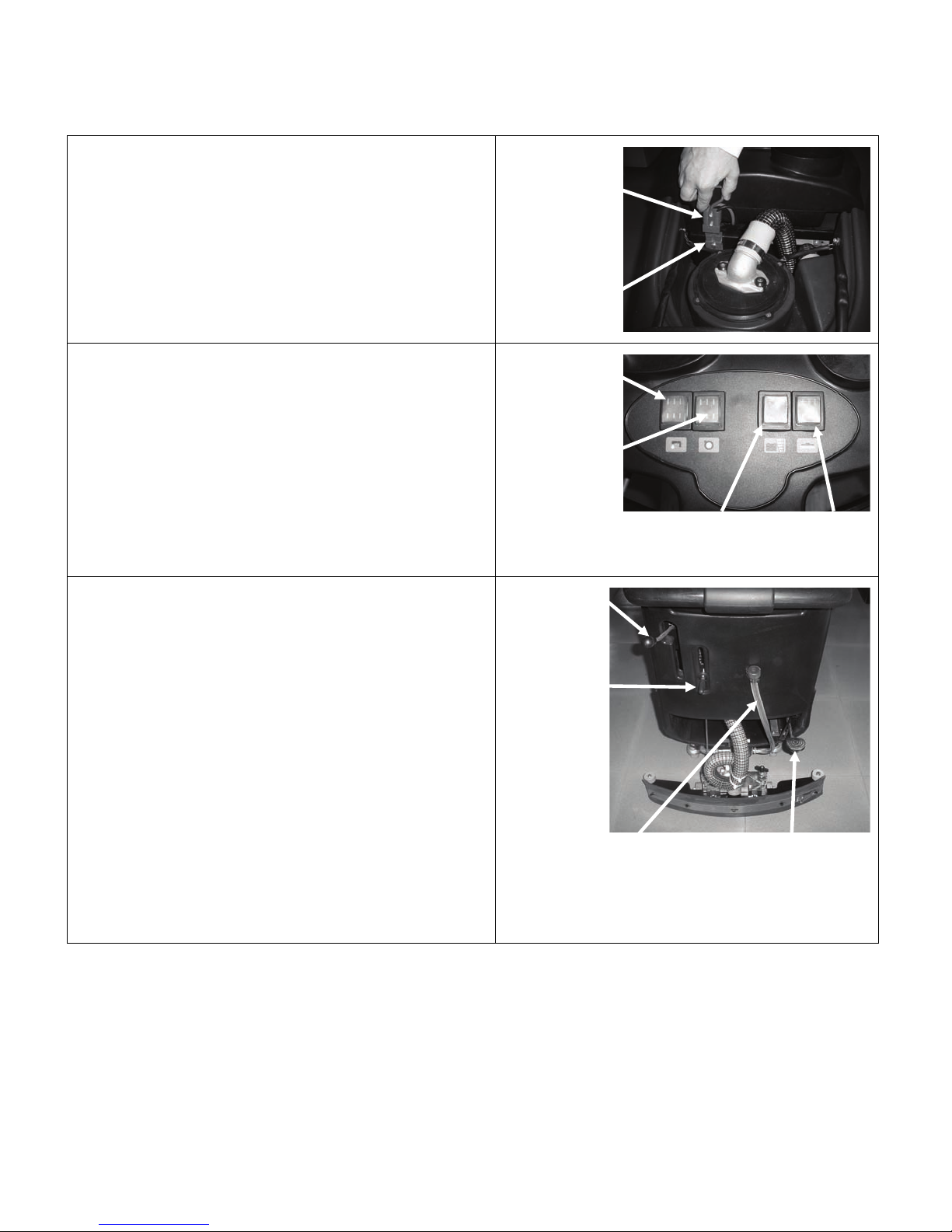
MACHINE OPERATION
1) Connect machine connector to the battery
connector.
2) Turn on the brush motor switch. Battery
charge indicator will illuminate indicating the
charge level of the batteries. If the indicator is
flashing the batteries need to be charged.
Please note that the scrubbing brushes will
not rotate until the hand switch lever is
engaged.
3) Turn on the water solenoid valve switch.
4) Turn on the vacuum motor switch.
5) Adjust the flow rate of the cleaning solution
with lever. Moving the solution flow control
lever downward increase the flow rate and
raising the lever decreases the flow rate.
There should be enough solution to wet the
floor uniformly, but not so much that the water
gets past the splash guard. Remember that
the correct solution quantity depends on the
type of floor, the dirt level and the scrubbing
speed.
6) Release and raise the brush base lift lever to
lower the brush base.
7) Lower the squeegee using the squeegee lift
lever.
Machine
Connecto
Battery
Connecto
Water
Solenoid
Switch
Vacuum
Motor
Switch
Squeegee
Lift Leve
Solution
Flow
Control
Lever
Battery Charge
Indicator
Solution
Tank
Drain
Hose
Brush Motor
Switch
Brush Base
Lift Leve
Page 9 of 38

r
MACHINE OPERATION
8) SCRUBBING
This machine is equipped with brush assist
propulsion. Depress the handle switch lever.
The scrub brushes will begin to rotate and
solution will begin to flow. During the first few
yards of operation, check that the quantity of the
cleaning solution is sufficient to wet the floor and
that the squeegee dries the floor surface.
WARNING! Always lift the squeegee when
moving backwards.
9) OVER FILL PROTECTION
The machine is equipped with a float that stops
the vacuum exhaust air flow when the recovery
tank is full. Vacuum motor does not stop
operating but the vacuum exhaust air flow rate is
greatly reduced. When this occurs, empty the
recovery tank by removing the drain plug on the
drain hose and then empty the recovery tank.
WARNING! Use gloves for protection
from contact with dangerous solutions.
Handle Switch
Leve
Float
Drain Plug
Page 10 of 38
r
r
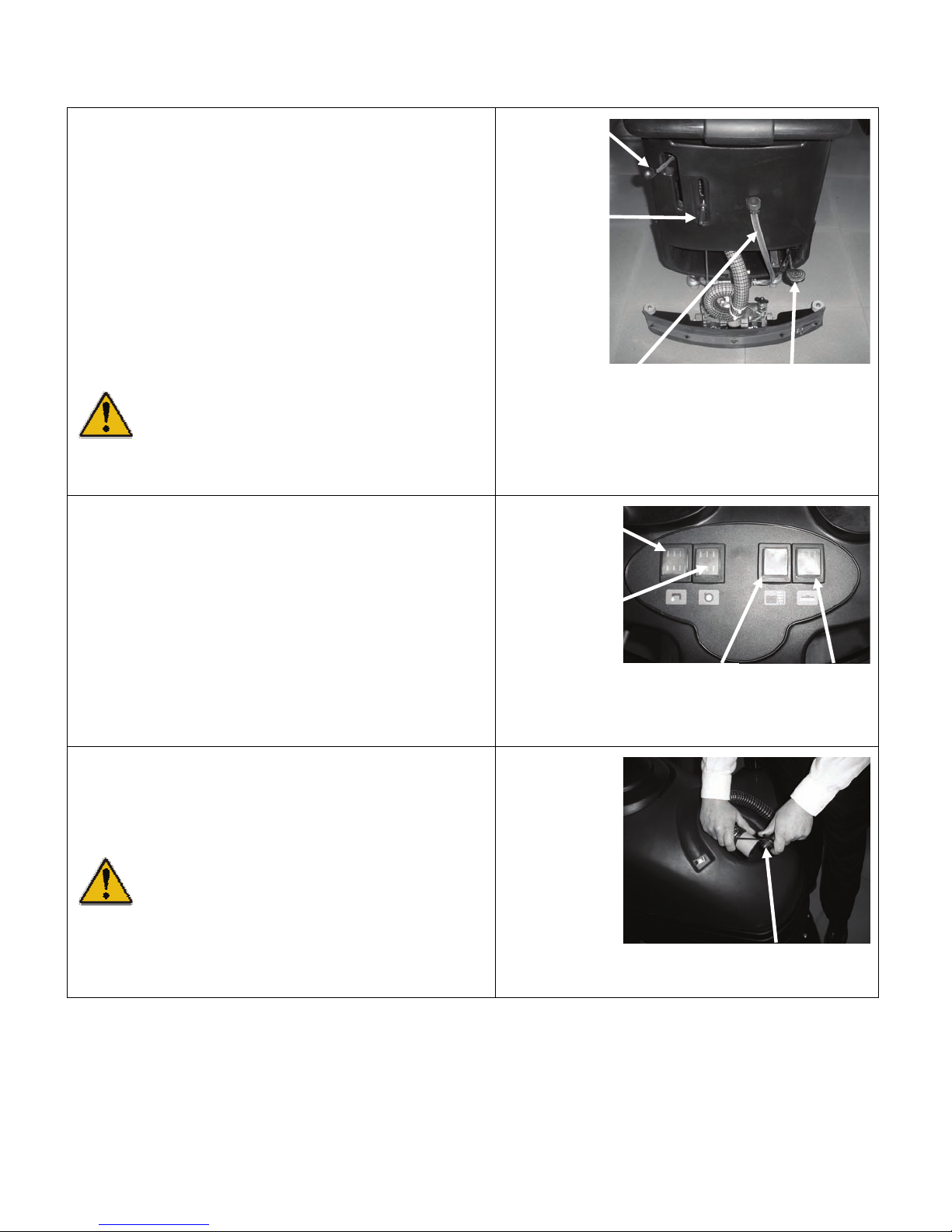
UPON COMPLETION OF MACHINE USE
After finishing your work and before any type of
maintenance is done, it is necessary to do the
following:
1) Close the water valve by raising the solution
flow control lever.
2) Raise the brush base by stepping down
locking the brush base lift lever. To lock the
lever move your foot to the right while the
lever is pressed down.
3) Lift the squeegee by raising the squeegee lift
lever and locking it by moving the lever to the
left.
WARNING! The squeegee blades can
be damaged if the squeegee is not raised
during storage or transport.
4) Switch off the water solenoid valve switch.
5) Switch off the brush motor switch.
6) Switch off the vacuum motor switch.
7) Transport the machine to the location where
the recovery tank should be emptied.
Squeegee
Lift Leve
Solution
Flow
Control
Lever
Water
Solenoid
Switch
Vacuum
Motor
Switch
Solution
Tank
Drain
Hose
Battery Charge
Indicator
Brush Base
Lift Leve
Brush Motor
Switch
8) Remove the drain hose at the front of the
recovery tank.
9) Remove the drain plug and empty the
recovery tank.
WARNING! Use gloves for protection
from contact with dangerous solutions.
10) Remove the brushes or pad drivers and clean
them with clear water.
Drain Plug
Page 11 of 38

r
DAILY MACHINE MAINTENANCE
CLEANING THE RECOVERY TANK
1) Empty the recovery tank by removing the drain
plug from the drain hose.
WARNING: Use gloves for protection from
contact with dangerous solution.
Drain Plug
2) Lift the cover of the recovery tank.
3) Take off the vacuum cover by rotating it
counter clockwise.
4) Remove the filter and its housing.
5) Rinse the tank with clean water.
CLEANING THE VACUUM FILTER
6) Lift the cover.
7) Take off the vacuum cover by rotating it
counter clockwise.
8) Remove the filter and its housing.
9) Use clear water to clean the walls and the
bottom of the filter.
10) Remove the filter and its housing.
11) Wash all components thoroughly.
12) Reassemble repeating the above operations
in reverse.
Vacuum
Cove
Squeegee
Hose
Page 12 of 38

DAILY MACHINE MAINTENANCE
CLEANING THE SQUEEGEE
To obtain the best drying results, keep the
squeegee clean. To clean the squeegee it is
necessary to:
13) Remove the vacuum hose from the
squeegee.
14) Lift locking latches. Remove the squeegee
assembly by pulling rearward.
15) Clean the inside of the squeegee thoroughly.
16) Clean the squeegee blades thoroughly.
17) Reassemble.
Vacuum
Outlet
Locking Latches
REPLACING THE SQUEEGEE BLADES
Check the squeegee blades for wear and if
necessary, change them. To replace the
squeegee blades:
18) Remove the squeegee vacuum hose from its
port.
19) Lift locking latches and pull squeegee
assembly rearward.
20) Release the band clamps by lifting the band
clamp latch.
21) Remove squeegee blades.
22) Rotate or replace the blades. Please note
that the squeegee has 4 useable edges so
you may be able to rotate squeegee blades.
23) To reassemble the squeegee, repeat the
above operations in reverse.
Band
Clamp
Latch
Squeegee
Blade
Band
Clamp
Band
Clamp
Latch
Squeegee
Blade
Band
Clamp
Page 13 of 38

DAILY MACHINE MAINTENANCE
BRUSH / PAD DRIVER REMOVAL
24) Lift the brush base by depressing the foot
level at the rear of the machine.
25) The photo shows the directions to rotate the
brushes to unlock them from the auto
scrubber. Clean the brushes with clear water.
Page 14 of 38
WEEKLY MACHINE MAINTENANCE
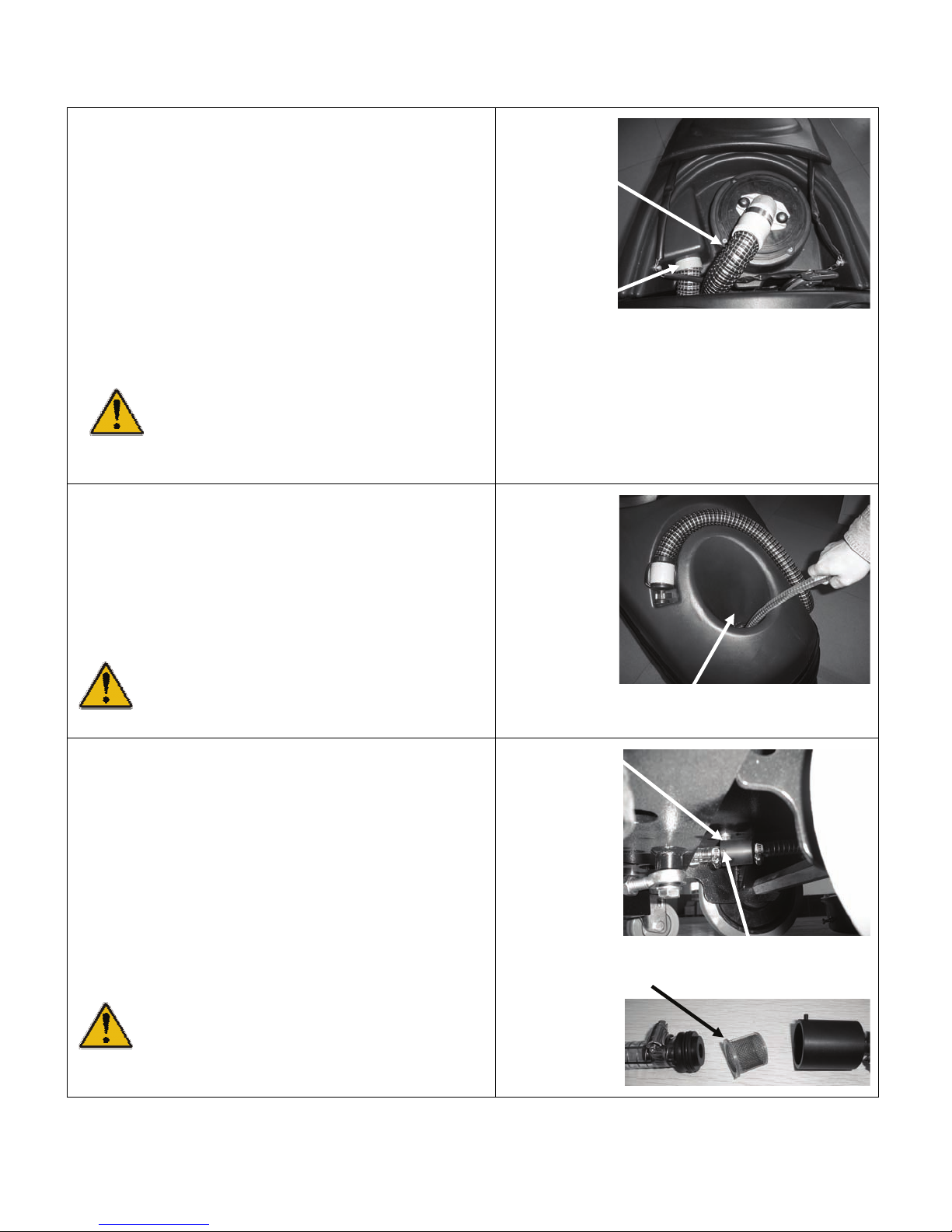
CLEANING THE SQUEEGEE HOSE
To obtain the best drying results, keep the
squeegee hose clean. To clean the squeegee
hose it is necessary to:
1) Take off the vacuum hose from its vacuum
port on the squeegee.
2) Remove the other end of the vacuum hose
from the recovery tank.
3) Wash the inner part of the hose with clean
water.
4) Reassemble.
WARNING: Do not wash the hose that
goes from the vacuum motor to the
vacuum cover.
SOLUTION TANK CLEANING
5) Remove the fill cap from the solution tank.
6) Rinse with clear water.
7) Remove the solution tank drain hose and cap
at rear of machine and empty the solution
tank.
WARNING: Use gloves for protection
from contact with dangerous solution.
Do Not
Wash
Vacuum
Cover
Hose
Wash
Squeegee
Hose
Solution Tank
Fill Opening
IN-LINE FILTER CLEANING
8) Drain solution tank.
9) Turn off solenoid valve.
10) Loosen set screw on in-line filter but do not
remove.
11) Pull rear hose rearward and separate in-line
filter into 2 pieces.
12) Remove the filter element and clean with
clear water.
13) Reassemble.
WARNING: Use gloves for protection
from contact with dangerous solution.
Page 15 of 38
In-Line Filter
Set Screw
Filter Element
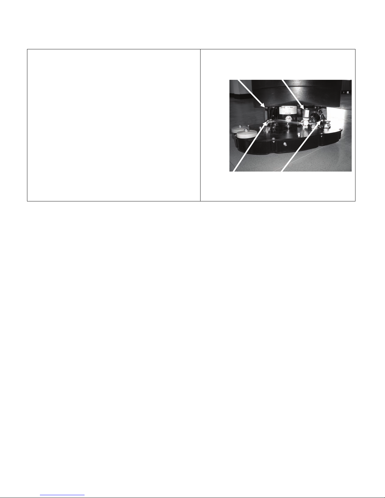
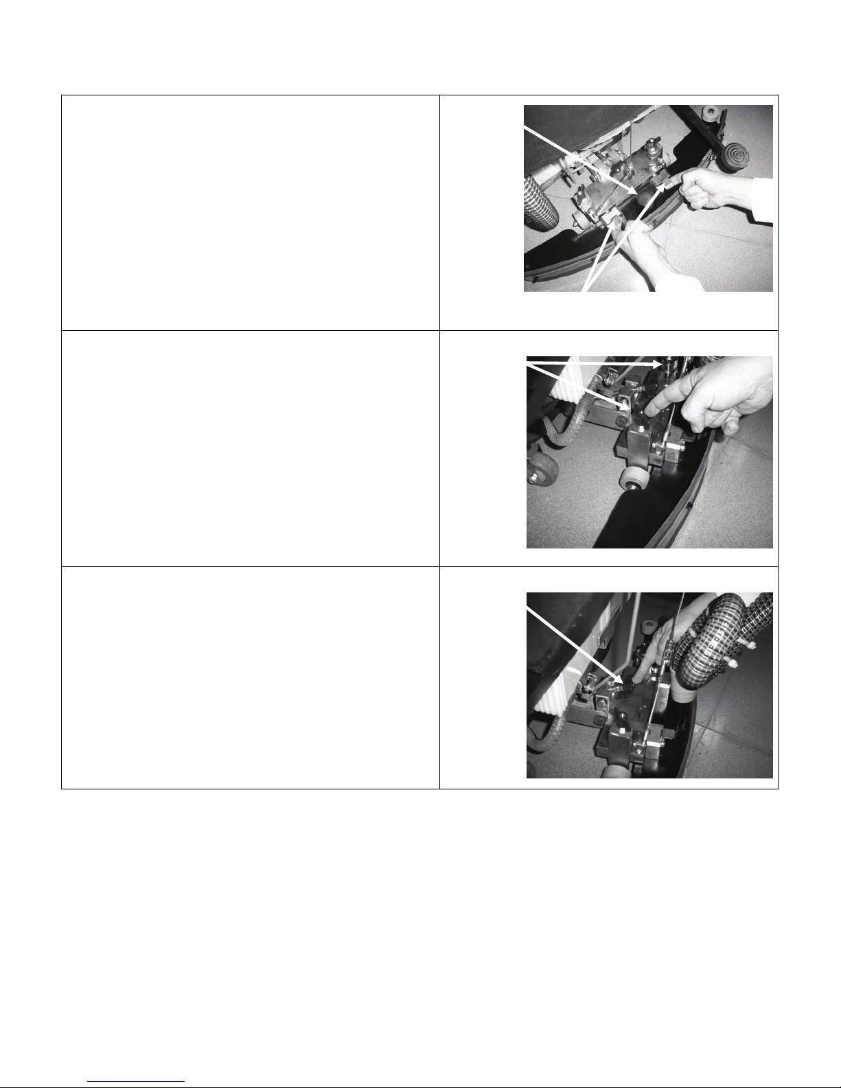
WATER SOLENOID MAINTENANCE
In the event that the water solenoid begins to
leak when turned off debris must be cleared at
the valve seat. To gain access the water
solenoid the scrub deck most be disassembled
from the lifting arms. Remove the 3 bolts shown
in the photo to release the scrub deck.
Remove
Water
Solenoid
Remove
Remove
Page 16 of 38

TROUBLE SHOOTING GUIDE
1) INSUFFICIENT WATER TO THE BRUSHES
a) Make sure the solution flow control valve is open.
b) Confirm that there is water in the solution tank.
c) Make sure solution dispensing tubes are not clogged or
obstructed.
2) THE MACHINE DOES NOT CLEAN SATISFACTORILY
a) Check the condition of the brushes or pads and replace them if necessary.
b) The brushes should be replaced when the bristles reach a length of 5/8 inches (15mm).
3) THE SQUEEGEE DOES NOT DRY THE FLOOR WELL
a) Check that the squeegee blades are clean.
b) Adjust the inclination of the squeegee.
c) Confirm the vacuum hose is correctly fitted into its port in the recovery tank and free from
Solution
Flow
Control
Lever
obstructions.
d) Replace the squeegee blades if worn.
e) Check that the vacuum motor switch is on.
f) Check the squeegee height adjustment (see "MACHINE PREPARATION" section).
4) EXCESSIVE FOAM PRODUCTION
a) Check that a low foaming detergent has been used. If required, add a small quantity of
defoamer liquid to the recovery tank. More foam is generated when a floor is lightly
soiled. Use less detergent if this is the case.
Page 17 of 38
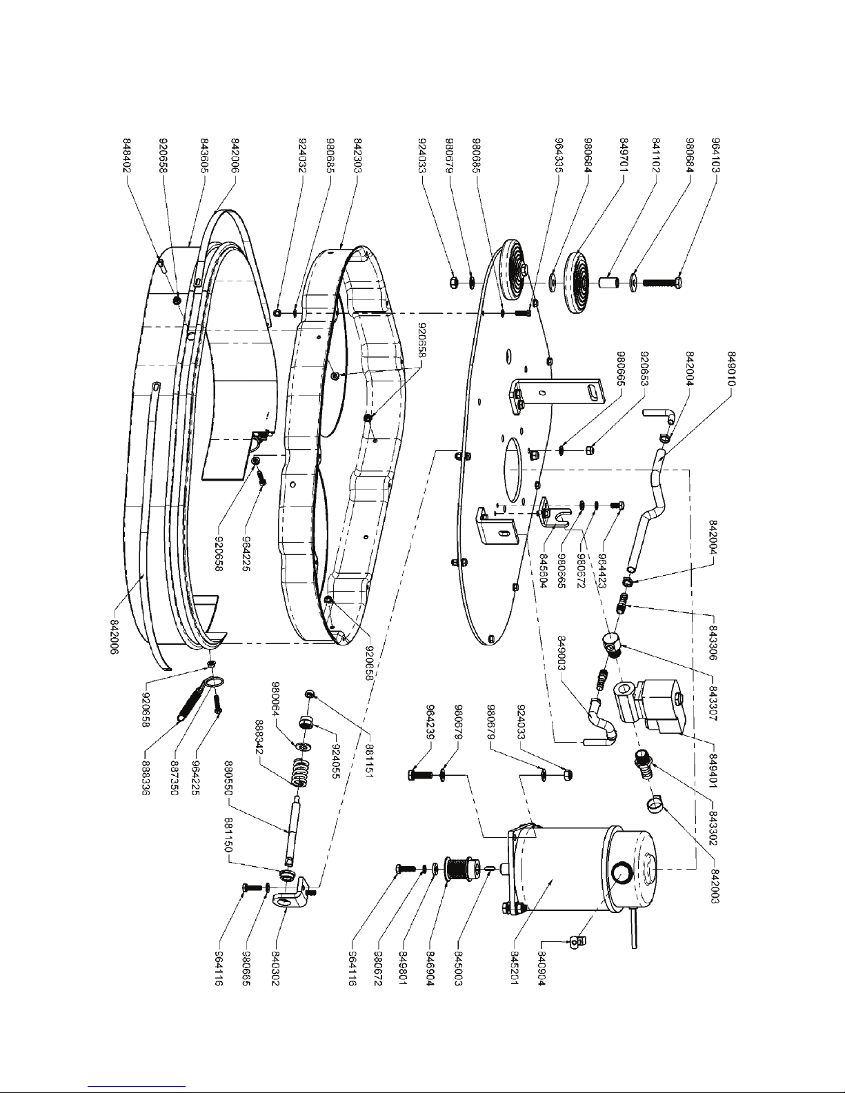
Brush Deck Assembly Drawing 1
Page 18 of 38

Drawing 1
PART NUMBER DESCRIPTION & SPECIFICATION QTY NOTE
840302 Brush Base Idler Arm Adj uster 1 EPOXY PAINT
840904 Carbon Brush 2
841102 Wheel Bushing 2 BRASS
842003 Hose Clamp 1 SS
842004 Hose Clamp 4 SS
842006 Clamp - Band 2 SS
842303 Base Cover 1 EPOXY PAINT
843302 Fitting Barbed 1
843306 Fitting Barbed 2
843307 Fitting 1
843605 Splash Guard 1
845003 Key - Motor Shaft 1
845201 Brush Motor 1
845604 Solenoid Valve Mount 1 ZINC
846904 Pulley 1 ZINC
848402 Stud Screw 1 SS
849003 Tubing 1
849010 Tubing 1
849401 Solenoid Valve 1
849701 Wheel 2
849801 Thrust Washer 1 ZINC
880550 Adjuster - Bolt 1 ZINC
881150 Bushing 1
881151 Bushing 1 ZINC
887350 Ring 2 ZINC
888336 Spring 2 ZINC
888342 Spring 1 ZINC
920653 M6 Nyloc Hex Nut Zinc 2 ZINC
920658 Nut Flange M5 Zinc 6 ZINC
924032 M5 Nyloc Hex Nut Zinc 9 ZINC
924033 NyLoc Hex Nut M8 Zinc 6 ZINC
924055 Lock Nut M10 1 ZINC
964103 Hex Bolt-Full M8x45 Zinc 2 ZINC
964116 Hex Bolt M6x20 Zinc 3 ZINC
964225 Hex Bolt M5X20 Zinc 2 ZINC
964239 Hex Bolt M8x25 Zinc 4 ZINC
964335 Hex Bolt M5X16 Zinc 9 ZINC
964423 Hex Bolt M6X12 Zinc 2 ZINC
980064 M10 Washer Flat Zinc 1 ZINC
980665 M6 Flat Washer Zinc 6 ZINC
980672 M6 Lock Washer Zinc 3 ZINC
980679 M8 Washer Flat Zinc 10 ZINC
980684 M8 Washers Flat L Zinc 4 ZINC
980685 M5 Washer Flat Zinc 18 ZINC
Page 19 of 38
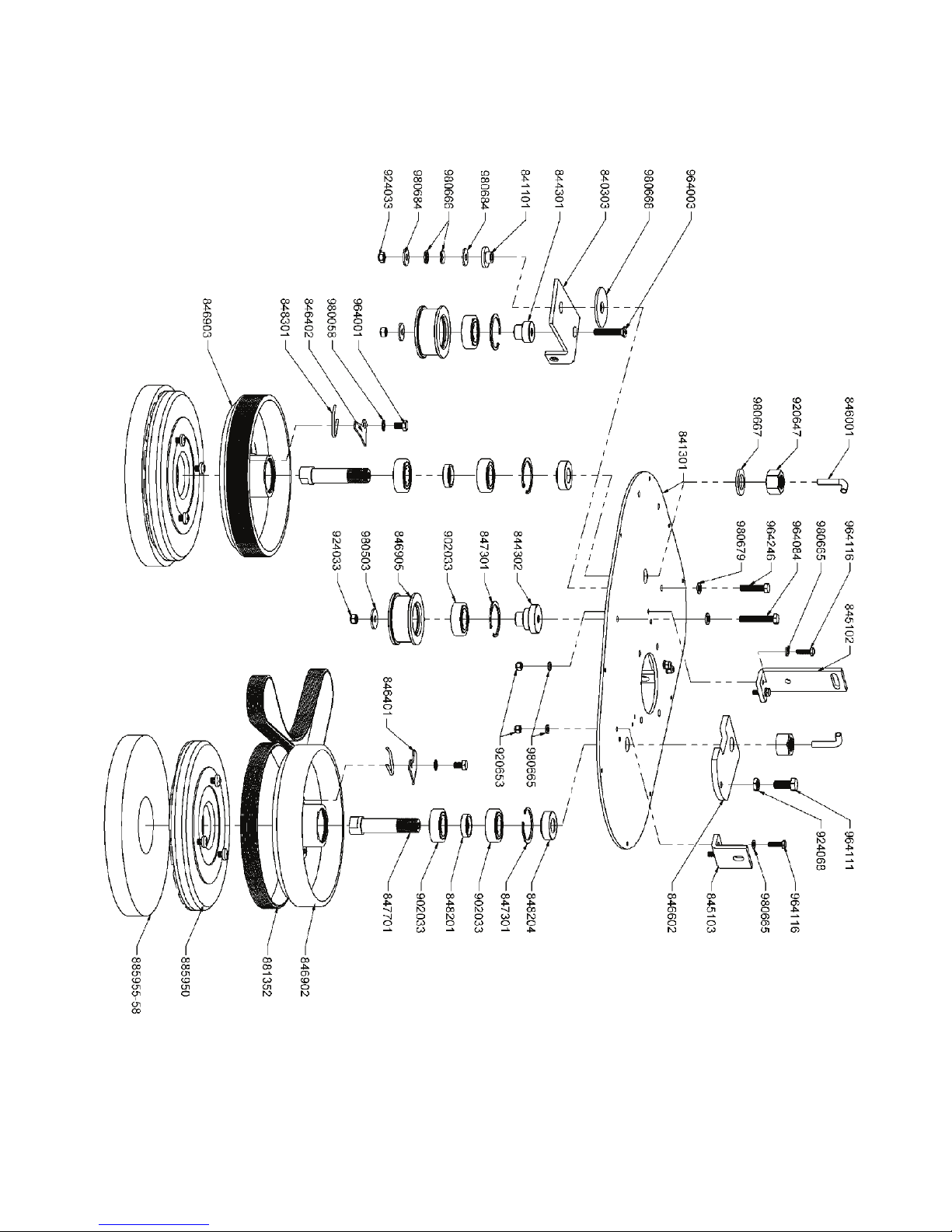
Brush Base Assembly Drawing 2
Page 20 of 38

Drawing 2
PART NUMBER DESCRIPTION & SPECIFICATION QTY NOTE
840303 Idler Arm 1 EPOXY PAINT
841101 Bushing 1
841301 Brush Base Deck 1 EPOXY PAINT
844301 Bearing Hub 1 ZINC
844302 Bearing Hub 1 ZINC
845102 Brush Base Dual Lift Link 1 EPOXY PAINT
845103 Brush Base Lift Link 1 EPOXY PAINT
846001 Pipe 2
846401 Left Spring Retaining Plate 1 ZINC
846402 Right Spring Retaining Plate 1 ZINC
846602 Plate 1 ZINC
846902 Brush Clutch Pulley 1
846903 Brush Clutch Pulley 1
846905 Idler Pulley 2 ZINC
847301 Reataining Ring 50 mm 4
847701 Brush Pulley Shaft 2 BLACK OXIDE
848201 Bearing Spacer 2 ZINC
848204 Spacer 2 ZINC
848301 Brush Retaining Spring 2 ZINC
881352 Brush Drive Belt 1
885950 Pad Driver 10 Inch 2
902033 Bearing 6
920647 Hex Nut M20 Zinc 2 ZINC
920653 M6 Nyloc Hex Nut Zinc 4 ZINC
924033 NyLoc Hex Nut M8 Zinc 3 ZINC
924068 Hex Nut M10 Thin Zinc 1 ZINC
964001 Hex Bolt M8x12 2 ZINC
964003 Screw Flat Head Torx Drive M8x45 1 ZINC
964084 Hex Bolt-Full M8X50 Zinc 1 ZINC
964111 Hex Bolt M10X25 Zinc 1 ZINC
964116 Hex Bolt M6x20 Zinc 4 ZINC
964246 Hex Bolt M8x35 Zinc 1 ZINC
980058 Washer Star Lock M8 2 ZINC
980503 M8 Washer XL Flat Zinc 2 ZINC
980665 M6 Flat Washer Zinc 8 ZINC
980666 Spring Washer M8x18 2
980667 Washer M20x39 Flat Zinc 1 ZINC
980668 Washer - Wide M16x56x3Thk 1
980679 M8 Washer Flat Zinc 2 ZINC
980684 M8 Washers Flat L Zinc 2 ZINC
885955-58 10 Inch Scrub Pad 2
Page 21 of 38

Main Frame Assembly Drawing 3
Page 22 of 38

Drawing 3
PART NUMBER DESCRIPTION & SPECIFICATION QTY NOTE
840301 Brush Deck Lift Idler Arm 1 ZINC
840306 Brush Deck Lift Arm ASM 1 ZINC
841105 Bushing 2 BRASS
842003 Hose Clamp 2 SS
842005 Clamp Bar 1 SS
842306 Pedal Cover 1
842701 Metal Disc 1 ZINC
843202 Main Frame Weldment 1 EPOXY PAINT
843314 In Line Filter Outer Housing 1
843315 In Line Filter Inner Housing 1
843316 In Line Filter Element 1
843602 Splash Guard 1
843801 Grommet 1
845801 O-Ring 21.2x2.65 1
847001 Brush Lift - Pivot Bloc k 6
847704 Wheel Shaft 1 ZINC
848211 Wheel Spacer 2 ZINC
848302 Spring 1 ZINC
849001 Tubing 1
849002 Tubing 1
849703 Castor 2
849704 Main Wheel 2
920648 M12 Nyloc Hex Nut Zinc 3 ZINC
920649 Hex Nut M8 Zinc 4 ZINC
920653 M6 Nyloc Hex Nut Zinc 6 ZINC
924033 NyLoc Hex Nut M8 Zinc 7 ZINC
964007 Hex Bolt M8X40 Zinc 1 ZINC
964083 Hex Bolt M8X30 Zinc 2 ZINC
964182 Screw M4x10 Pan Head Zinc 4 ZINC
964209 Hex Bolt M6X16 Zinc 4 ZINC
964230 Hex Bolt M12x65 Zinc 1 ZINC
964400 Flat Head Soc Hex Screw M6x16 Zinc 1 ZINC
964415 Hex Bolt M6x45 Zinc 6 ZINC
964437 Screw - SHCS M8x40 Zinc 2 ZINC
964442 Slotted Set Screw Cone Point M3x6 1 BLACK OXIDE
980043 Washer Flat M12 5 ZINC
980501 M6x22 OD Washer Flat Zinc 2 ZINC
980665 M6 Flat Washer Zinc 12 ZINC
980670 M6 External Lock Washer Zinc 2 ZINC
980671 M6 Washer Flat XL Zinc 2 ZINC
980672 M6 Lock Washer Zinc 2 ZINC
980676 M8 Washer - Plastic 2
980679 M8 Washer Flat Zinc 8 ZINC
980684 M8 Washers Flat L Zinc 5 ZINC
Page 23 of 38

Squeegee Arm Assembly Drawing 4
Page 24 of 38

Drawing 4
PART NUMBER DESCRIPTION & SPECIFICATION QTY NOTE
840304 Squeegee Link Arm W el dment 1 EPOXY PAINT
840501 Squeegee Adjuster Bolt ASM 1 ZINC
841103 Wheel Bushing 2
842404 Squeegee Lift Cable 1
842405 Squeegee Lift Cable 2
845001 Adjustment Knob 3
845601 Squeegee Mount Base 1 ZINC
845602 Squeegee Mount Base Pivot 1 ZINC
846701 Squeegee Attachment Pin 2 ZINC
847302 Retaining Ring 20mm x 1.2mm THK 2 BLACK OXIDE
847303 Retaining Ring 15mm x 1.0mm THK 2 BLACK OXIDE
847305 Squeegee Lift Ring 2 ZINC
847403 Rod End Male M12 Zinc 1 ZINC
847702 Squeegee Adjuster Front Shaft 1 ZINC
847703 Squeegee Adjuster Rear Shaft 1 ZI NC
848302 Spring 1 ZINC
848303 Spring - Squeegee Adjust 2 ZINC
848401 Squeegee Wheel Adjust i ng S tud 2 SS
848501 Wheel Strut Upright 2 ZINC
849702 Wheel 2
887341 E-Ring 9 mm ID 2 BLACK OXIDE
920615 Hex Nut M5 Zinc 2 ZINC
920648 M12 Nyloc Hex Nut Zinc 1 ZINC
920649 Hex Nut M8 Zinc 3 ZINC
920650 Hex Nut M12 Zinc 1 ZINC
920653 M6 Nyloc Hex Nut Zinc 4 ZINC
924033 NyLoc Hex Nut M8 Zinc 1 ZINC
964005 Flat Head Soc Hex Screw M8X25 3 ZINC
964116 Hex Bolt M6x20 Zinc 2 ZINC
964220 M6x45 Flat Hd Phil Zinc 2 ZINC
964243 Hex Bolt M12x100 Lg Zinc 1 ZINC
980043 Washer Flat M12 4 ZINC
980671 M6 Washer Flat XL Zinc 2 ZINC
980679 M8 Washer Flat Zinc 4 ZINC
980685 M5 Washer Flat Zinc 2 ZINC
Page 25 of 38

Squeegee Assembly Drawing 5
Page 26 of 38

Drawing 5
PART NUMBER DESCRIPTION & SPECIFICATION QTY NOTE
840701 Squeegee Blade Front 1
840702 Squeegee Blade Rear 1
841304 Squeegee Attachment Block 2 ZINC
842001 Band Clamp-Rear 1 SS
842002 Band Clamp-Front 1 SS
843201 Squeegee Frame Weldment 1 EPOXY PAINT
843311 Filler - Squeegee 2
845104 Latch ASM 2 ZINC
845105 Squeegee Attachment Bloc k Latch 2 ZINC
881145 Wheel Bushing 2 BRAS S
889742 Wheel 45 Dia 2
920649 Hex Nut M8 Zinc 2 ZINC
924033 NyLoc Hex Nut M8 Zinc 2 ZINC
925009 Roll Pin M5.5x12 SS 1 SS
930012 Revit M4x8 Lg Oval Head Semi-Tubular 4
964004 Hex Set Screw M6X8 2 BLACK OXIDE
964103 Hex Bolt-Full M8x45 Zinc 2 ZINC
964209 Hex Bolt M6X16 Zinc 2 ZINC
964232 Hex Bolt M6x25 Zinc 4 ZINC
980665 M6 Flat Washer Zinc 6 ZINC
980672 M6 Lock Washer Zinc 4 ZINC
980679 M8 Washer Flat Zinc 4 ZINC
980681 Washer M4 Flat Zinc 4 ZINC
980684 M8 Washers Flat L Zinc 2 ZINC
Page 27 of 38

Solution Tank Assembly Drawing 6
Page 28 of 38

Drawing 6
PART NUMBER DESCRIPTION & SPECIFICATION QTY NOTE
841302 Rear Battery Bracket 1 ZINC
841303 Side Battery Bracket 1 ZINC
842003 Hose Clamp 2 SS
842705 Sound Deadener 1
843308 Fitting Barbed 1
843309 Fitting Barbed 1
843310 Filter Basket 1
843401 Battery Plastic Gasket 1
843402 Side Battery Gasket 1
843406 Conical Tank Gasket 1
844702 Fitting 1
845106 Brush Deck Lift Latch 1 EPOXY PAINT
845107 Lever - Valve 1 ZINC
845111 Water Control Label 1
845113 Squeegee Lift Label 1
846403 Plate Wire Retai ning 3
846603 Water Valve Lim it Plate 1
847401 Rod - Connecting 1 ZINC
848302 Spring 1 ZINC
848601 Solution Tank 1
849007 Drain Tubing - Solution Tank 1
849402 Valve 1
882440 Hook 1 SS
885044 Knob 1
886852 Cap 1
920615 Hex Nut M5 Zinc 1 ZINC
924051 M5 Retaining Nut 1 ZINC
925008 Cotter Pin M2x10 1 SS
964127 Screw M4X8 Pan Head Zinc 1 ZINC
964224 M5.5X16 Pan Head Plastite Screw 4 ZINC
964228 M3x9.5 Pan Head Plastite Screw 6 ZINC
964231 ST M4.2X12 Pan HD PL Zinc 2 ZINC
964398 Hex Bolt Full-THD M6x25 SS 1 SS
964423 Hex Bolt M6X12 Zinc 2 ZINC
964435 Hex Bolt M8x90 Zinc 4 ZINC
980060 Plastic Washer M5 1
980504 M6x30 OD Washer Flat Plastic 2
980665 M6 Flat Washer Zinc 2 ZINC
980671 M6 Washer Flat XL Zinc 4 ZINC
980672 M6 Lock Washer Zinc 2 ZINC
980679 M8 Washer Flat Zinc 1 ZINC
980680 Lock Washer M4 Zinc 1 ZINC
980682 M3 Waher Flat Zinc 6 ZINC
980684 M8 Washers Flat L Zinc 4 ZINC
980685 M5 Washer Flat Zinc 1 ZINC
980702 M4 Large Flat Washer Zinc 1 ZINC
Page 29 of 38

Recovery Tank Assembly Drawing 7
Page 30 of 38

Drawing 7
PART NUMBER DESCRIPTION & SPECIFICATION QTY NOTE
842007 Hose Clamp 1
842304 Recovery Tank Cover 1
842305 Solution Tank Cover 1
842403 Chain 2 SS
842410 Chain For Lift 1
843405 Tank Gasket 1
844101 Recovery Tank Vacuum Hose 1
844102 Squeegee Vacuum Hose 1
844103 Drain Hose 1
845110 Recovery Tank Cover Label 1
845131 Label For Lifting 1
846801 Plug - Solution Tank Fill 1
847304 Ring - Filter Holder 1
848101 Sleevee 2
848102 Sleeve For Lift 1
848608 Recovery Tank 1
849004 Tubing 1
882440 Hook 1 SS
882442 Vacuum Outlet Port 1
883343 Filter Basket 1
883344 Float 1
883441 Gasket 1
883442 Gasket 1
883446 Gasket 1
886841 Filter Cover 1
887440 Float Rod 1 SS
888551 Splash Protector 1
924045 M5 Nyloc Hex Nut Stainless 2 SS
925603 Cotter Pin M2x20 2 SS
964063 FLHD Screw Ph Drive SS 4.2x13 4 SS
964105 Oval HD PHL Screw M5x25 SS 2 SS
964231 ST4.2X13 Pan HD PL Zinc 2 ZINC
964438 Screw M5x16 Pan Head Zinc 4 ZINC
980060 Plastic Washer M5 2
980502 M5 x 15OD Flat Washer Zinc 4 ZINC
980675 M6 Flat Washer Stainless 2 SS
980704 M5 Washer Flat SS 2 SS
S611A Hose Clamp 45mm 3 SS
Page 31 of 38
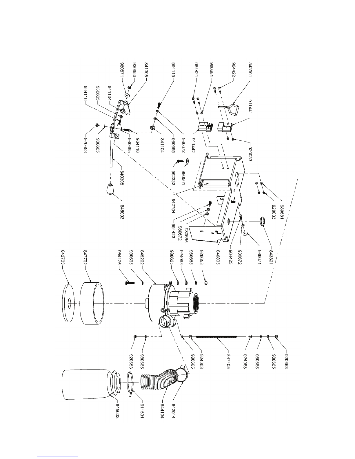
Vacuum Assembly Drawing 8
Page 32 of 38

Drawing 8
PART NUMBER DESCRIPTION & SPECIFICATION QTY NOTE
840305 Lever Arm Weldment 1 ZINC
840805 Bracket-Weldment 1 EPOXY PAINT
841104 Bushing 2 BRASS
841305 Lever Bracket 1 ZINC
842014 Hose Clamp 50mm 1 SS
842702 Vacuum Motor Sound Deadener 1
842703 Vacuum Motor Sound Deadener 1
842704 Sound Deadener 1
843801 Grommet 1
843901 Connector Handle 1
844104 Vacuum Exhaust Hose 1
845002 Lever Arm Knob 1 ZINC
845202 24VDC Vacuum Motor - SIX 1
845603 Muffler 1
847405 Rod - Connecting 1 ZINC
911441 Connector Male 50A 1
911442 Connector Female 50A 1
911531 Hose Clamp 1
920033 M4 Hexagon Lock Nut 4 ZINC
920653 M6 Nyloc Hex Nut Zinc 6 ZINC
924063 Hex Nut M6 Zinc 4 ZINC
962332 ST M6.3X22 Pan Head Zinc 2 ZI NC
964116 Hex Bolt M6x20 Zinc 3 ZINC
964176 Hex Bolt M6X30 Zinc 2 ZINC
964421 Screw M4x25 Pan HD PL Zinc 2 ZINC
964422 Screw M4x20 Pan HD PL Zinc 2 ZINC
964423 Hex Bolt M6X12 Zinc 5 ZINC
980501 M6x22 OD Washer Flat Zinc 2 ZINC
980665 M6 Flat Washer Zinc 18 ZINC
980671 M6 Washer Flat XL Zinc 2 ZINC
980672 M6 Lock Washer Zinc 6 ZINC
980681 Washer M4 Flat Zinc 4 ZINC
Page 33 of 38
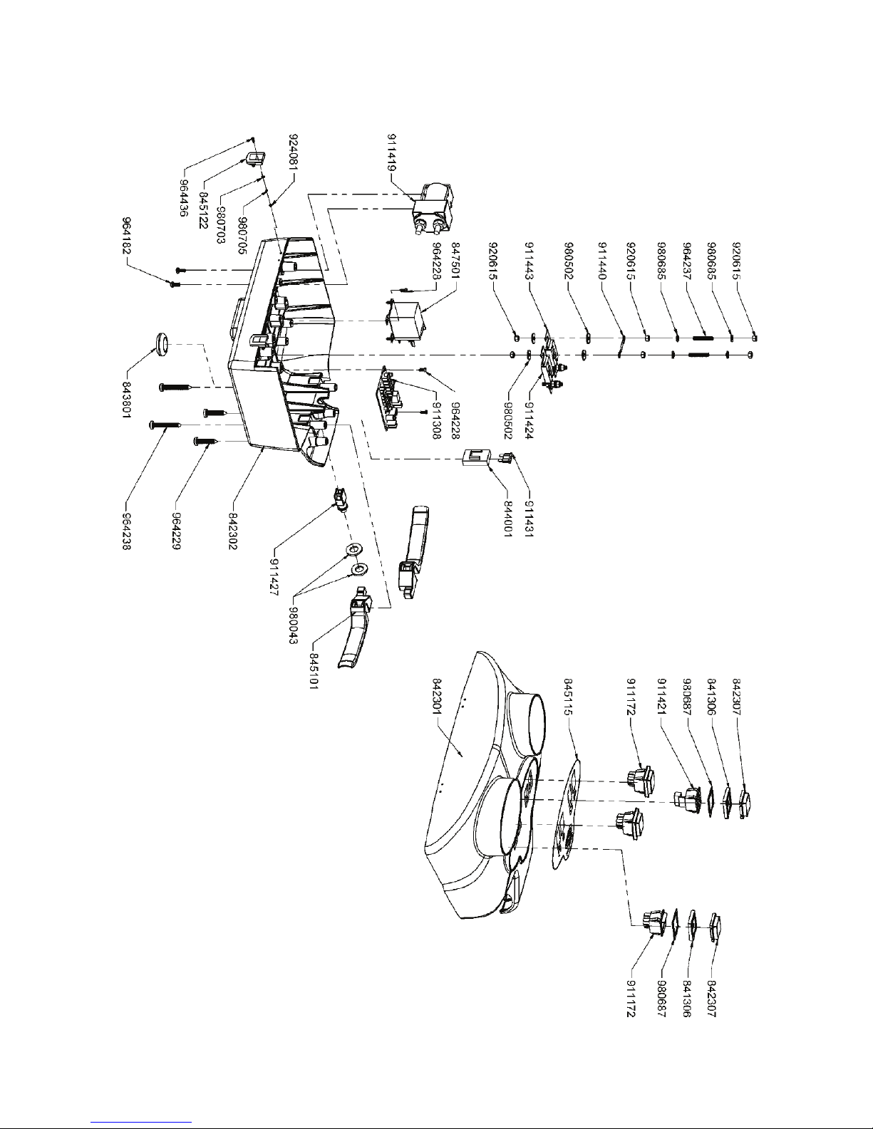
Switch Box Assembly Drawing 9
Page 34 of 38

Drawing 9
PART NUMBER DESCRIPTION & SPECIFICATION QTY NOTE
841306 Bezel - Rocker Switch 4
842301 Cover Upper Switch Box 1
842302 Cover Lower Switch Box 1
842307 Cover - Rocker Switch 4
843801 Grommet 1
844001 Fuse Holder 1
845101 Scrubber Lever - Switch Box 2
845115 Switch Box label 1
845122 Switch Box Latch 2
847501 Traction & Vacuum Motor Relay 1
911172 Rocker Switch Green 3
911308 Battery Check Card 1
911419 Brush Motor Relay 1
911421 Battery Charge Numberic Indicat or 1
911424 Fuse 30Amp 1
911427 Microswitch 1
911431 Fuse 3Amp 1
911440 Jumper Wire 1
911443 Fuse 50Amp 1
920615 Hex Nut M5 Zinc 12 ZINC
924081 Hex Nut M2 Zinc 8 ZINC
964182 Screw M4x10 Pan Head Zinc 2 ZINC
964228 M3 x9.5 Pan Head Plastite Screw 6 ZINC
964229 M6.0x32 Pan Head Plastite Screw 2 ZINC
964237 Set Screw Socket M5X30 Zinc 4 ZINC
964238 Plastite Screw M6x45 Pan HD PL Zinc 2 ZINC
964436 Flat HD PHL Screw M2x8 Zinc 8 ZINC
980043 Washer Flat M12 2 ZINC
980502 M5 x 15OD Flat Washer Zinc 8 ZINC
980685 M5 Washer Flat Zinc 8 ZINC
980687 Special Washer 4
980703 M2 Flat Washer Zinc 8 ZINC
980705 Spring Lock Washer M2 Zinc 8 ZINC
Page 35 of 38

Electrical Schematic Drawing 10
Page 36 of 38

Drawing 10
PART NUMBER DESCRIPTION & SPECIFICATION QTY
844505 Wire Harness 1
844506 Wire Harness 1
844507 Wire Harness 1
844508 Wire Harness 1
844509 Wire Harness 1
844510 Wire Harness 1
844511 Wire Harness 1
844512 Wire Harness 1
844513 Wire Harness 1
844514 Wire Harness 1
844515 Wire Harness 1
844516 Wire Harness 1
844517 Wire Harness 1
844518 Wire Harness 1
844519 Wire Harness 1
844520 Wire Harness 1
844521 Wire Harness 1
844522 Wire Harness 1
844523 Wire Harness 1
844526 Wire Harness 1
844527 Wire Harness 1
844528 Wire Harness 1
844529 Wire Harness 1
844530 2 Cables black-red and connector 50A 1
844531 2 Cables black-red and connector 50A 1
845201 Brush Motor 1
845202 24VDC Vacuum Motor - SIX 1
847501 Traction & Vacuum Motor Relay 1
849401 Solenoid Valve 1
911172 Rocker Switch Green 3
911308 Battery Check Card 1
911401 Capacitor 470nF-250V 1
911402 Resistor 220 Ohm 1
911419 Brush Motor Relay 1
911421 Battery Charge Numberic Indicator 1
911424 Fuse 30Amp 1
911427 Microswitch 1
911431 Fuse 3Amp 1
911440 Jumper Wire 1
911443 Fuse 50Amp 1
911490 Butt Connector 6.0mm Yellow 2
911491 Spade Connector Famale Ins 6.3x5.0mm Yellow 2
911495 Spade Connector male Ins 6.3x5.0m m Yellow 2
68000154 Cable Bridge 1
72500008 Diode IN4007 6
Page 37 of 38

WARRANTY POLICY
TRIPLE S LIMITED WARRANTY
The Triple S Ace 20BA has been manufactured, tested and inspected in accordance with specific
engineering requirements. This machine is WARRANTED to be free from defects in workmanship
and materials for periods as follows from the date of purchase.
Ten (10) Years Parts, One (1) Year Labor – Polyethylene Components
Five (5) Years Parts, One (1) Year Labor – Main Frame
Two (2) Years Parts, One (1) Year Labor – Brush Drive Motors
One (1) Year Parts & Labor – All other components unless excluded below
Travel time for warranty repair is authorized for a period of ninety (90) days following the date of sale
to the end user, with a maximum of three (3) hours per claim.
This warranty extends to the original user/purchaser and only when used, operated and maintained in
accordance with Triple S Operating and Maintenance instructions.
This warranty does not apply to certain wear parts and accessories of the machine such as electrical
cords, carbon motor brushes, floor brushes, belts, hoses, tools, squeegee blades, etc., nor does it
apply to damage or failure caused by improper use, abuse or neglect. Warranty credit of return parts
including motors, pumps, etc., is subject to incoming inspection of those items.
To secure repair under this warranty, the following procedure should be taken:
1. After the expiration of the ninety (90) day travel time warranty period, the customer is responsible
for warranty travel payment for the inoperative machine or warranted parts must be delivered to the
authorized dealer with shipping and delivery charges prepaid. If unable to locate the Dealer, you may
contact Triple S at the address listed herein for the location of the nearest Triple S repair center or
agent or for other instructions pertaining to your warranty difficulty.
2. Upon compliance with the above warranty procedure, all warranted repairs will be completed at no
additional charge or cost to the user.
3. Only Triple S or its authorized dealers and agents may make no charge warranty repairs on this
product. All others do so at their own risk.
This warranty limits Triple S liability to the repair of the product and/or warranted parts replacement
and does not include incidental or consequential damages arising from the use of a Triple S machine
whether defective or not.
BATTERY WARRANTY
In addition to the terms above, any original equipment Triple S battery which becomes unserviceable
under normal use within a period of ninety (90) days from the date of sale to the original user will be
repaired or replaced with one of equal specification at our option, F.O.B. any authorized Triple S
sales or service branch, with no charge to user, except transportation costs. After the expiration of
the above ninety (90) day period, any battery which fails under normal use will be adjusted to the
original user with a new battery of equal specification on a twelve (12) month pro rata basis from the
date of purchase. Adjustments will be determined using the then current list price, plus transportation
costs. Warranty is rendered null and void if battery is not kept filled to the proper level with
DISTILLED WATER.
This warranty is in lieu of all other expressed or implied warranties and is extended to the original
purchaser/user.
04/2008 Page 38 of 38 PN 845632
 Loading...