


low res. Internet brochurelow res. Internet brochure
PSxxx-90 Laser Scanner
low res. Internet brochure
User’s Manual
PS300-90
PS250-90
PS100-90
PS250-90 HT
PS100-90 HT
Triple-In GmbH | Poppenbütteler Bogen 64, D-22339 Hamburg, Germany

Content
Triple-IN
GmbH
1 INTRODUCTION ................................................................................................................ 3
1.1
A
BOUT PS LASER SCANNERS
1.2
A
BOUT THIS DOCUMENT
low res. Internet brochure
low res. Internet brochure
1.3
W
EBSERVER WITH LATEST DOCUMENTS AND FIRMWARE UPDATES
2 SAFETY INSTRUCTIONS ..................................................................................................... 5
3 ABOUT THE PSXXX-90 LASER SCANNER ............................................................................. 6
3.1
N
AMES AND FUNCTIONS OF COMPONENTS
3.2
S
YSTEM PARTS
3.3
T
RIPLE
3.4
S
ENSOR ORIGIN AND SCAN AREA
3.5
PS100-90-HT
4 TRANSPORT AND INSTALLATION ...................................................................................... 11
4.1
G
ENERAL HANDLING INSTRUCTIONS
4.2
P
ACKAGE AND TRANSPORT
4.3
M
ECHANICAL MOUNTING
5 CONNECTORS .................................................................................................................. 13
5.1
P
HOENIX
5.2
D
ATA AND POE CONNECTOR
5.3
S
ERIAL INTERFACE CONNECTOR
................................................................................................................... 7
-IN’S KEM T
FOR HIGH SURFACE TEMPERATURES
SPEEDCON
................................................................................................. 3
...................................................................................................... 3
............................................... 4
.............................................................................. 6
IME-OF-FLIGHT TECHNOLOGY
........................................................................................... 9
..................................................................................... 11
................................................................................................. 11
.................................................................................................. 12
®
QUICK LOCKING SYSTEM
.............................................................................................. 14
........................................................................................... 16
..................................................................... 7
.................................................................. 9
..................................................................... 13
6 SETTING INTO OPERATION ............................................................................................... 21
6.1
W
INDOWS® SOFTWARE TOOLS
6.2
P
OWER-UP
6.3
S
ERIAL
6.4
E
THERNET CONNECTION
6.5
PS L
6.6
T
AKING SCANS
6.7
F
ILTERS AND MASTER ECHO SELECTION
6.8
S
ETTING UP THE DIGITAL SWITCHING OUTPUTS
6.9
C
ONTROLLING THE HEATER (OPTIONAL
6.10 R
7 MAINTENANCE ................................................................................................................ 48
7.1
7.2
8 TROUBLE SHOOTING ........................................................................................................ 52
8.1
8.2
9 TECHNICAL SPECIFICATIONS............................................................................................. 55
9.1
EADING THE EXTERNAL INCREMENTAL ENCODER (OPTIONAL
C
LEANING
U
PDATING THE FIRMWARE
LED I
S
ELF-TEST MESSAGES AND SYSTEM HEALTH STATUS
T
ECHNICAL DATA
..................................................................................................................... 24
RS232
COMMUNICATION
ASER SCANNER CONFIGURATION
................................................................................................................. 36
....................................................................................................................... 48
NDICATORS
.............................................................................................................. 52
............................................................................................................. 55
............................................................................................ 21
........................................................................................ 24
.................................................................................................... 28
................................................................................... 31
................................................................................. 40
...................................................................... 43
) ................................................................................ 46
) ................................................... 46
................................................................................................. 48
................................................................. 53
© Triple-In GmbH • 11/01/2017 14:31:00
PSxxx-90 Laser Scanner User's Manual
1

9.2
9.3
9.4
9.5
9.6
9.7
9.8
PS
XXX
.90 HT V
L
ASER SPOT SIZE AND SIGMA DIAGRAMS
L
ASER SPOT PATTERN
3D CAD M
PS
XXX
-90 L
S
ERIAL MULTIFUNCTION CABLE LAY OUT
E
THERNET AND POE CABLE LAYOUT
ERSIONS
........................................................................................................ 59
ODEL
.............................................................................................................. 61
ASER SCANNER OUTLINES
Triple-IN
GmbH
.................................................................................................... 57
............................................................................... 58
.................................................................................. 62
................................................................................ 63
...................................................................................... 64
low res. Internet brochure
low res. Internet brochure
10 INDEX .............................................................................................................................. 65
10.1 T
10.2 D
ABLE OF FIGURES
OCUMENT VERSIONS
............................................................................................................ 65
....................................................................................................... 66
Copyright © 2017 by Triple-IN GmbH
All rights reserved, including the right to reproduce this book or portions
thereof in any form whatsoever.
All trademarks, product names and logos are the property of their respective
owners.
Text, photographs, and illustration by C. Bruelle-Drews/Triple-IN GmbH
© Triple-In GmbH • 11/01/2017 14:31:00
PSxxx-90 Laser Scanner User's Manual
2

Triple-IN
GmbH
1 Introduction
1.1 About PS Laser Scanners
Triple-Ins PS Laser Scanners are 2D Laser Scanners for outdoor automation,
low res. Internet brochure
low res. Internet brochure
industrial applications, security and surveying.
• long range
• large scan angle
• small spot size
• accurate in range and angle
• fast scan rate
• robust, IP67
• real time Ethernet
PSxxx-90 is the backbone of the whole Triple-IN sensors portfolio, providing
rapidly and efficiently accurate and detailed 3D data. PSxxx-90 is suitable for both
indoor and outdoor applications, ensuring also goals achievement for existing
systems integration.
1.2 About this document
This document describes the PSxxx-90 Laser Scanner family. It is related to the
PS Firmware Version 3.03.16
If you or your colleagues have any comments on this manual, we would be
grateful to hear from you. Please write to:
Triple-IN GmbH
Poppenbütteler Bogen 64
D-22399 Hamburg
Germany
Telefon +49(0)40 50091998
Mail
info@triple-in.de
© Triple-In GmbH • 11/01/2017 14:31:00
PSxxx-90 Laser Scanner User's Manual
3

Triple-IN
GmbH
1.3 Webserver with latest Documents and Firmware
Updates
The latest version of this document and the latest firmware updates can be
obtained from Triple-IN’s webserver:
low res. Internet brochure
low res. Internet brochure
Picture 1 Triple-IN webserver login
Please contact Triple-IN to get access to the reserved area of the webserver:
info@triple-in.de
© Triple-In GmbH • 11/01/2017 14:31:00
PSxxx-90 Laser Scanner User's Manual
4

2 Safety Instructions
Triple-IN
GmbH
ATTENTION
low res. Internet brochure
low res. Internet brochure
• Before using the PS Laser Sensor, the user manual must be read and all
instructions must carefully be observed.
• The PS Laser Scanner must be installed, configured, and serviced only by
qualified personnel.
• National and international rules and regulations must be applied according
to the field of application and usage.
• PS Laser Sensor cannot be used as a safety device.
ATTENTION
• Measurement Laser is a laser class 1 product. Emits invisible light (905 nm).
Do not look into the laser beam!
• Red laser marker is a laser class 2 product. Emits visible light (660 nm). Do
not look into the laser beam!
ATTENTION
Only authorized personnel are allowed to perform the electrical installation
work.
To reduce the risk of electric shock, do not remove the cover. Device contains
high voltage components!
Connect and disconnect electrical linkages only under de-energized conditions.
WARNING
Do not open the PS Laser Scanner.
If opened, the mechanical adjustment will be damaged and warranty will get
void!
© Triple-In GmbH • 11/01/2017 14:31:00
PSxxx-90 Laser Scanner User's Manual
5

Triple-IN
Front
window
GmbH
3 About the PSxxx-90 Laser Scanner
3.1 Names and Functions of Components
low res. Internet brochure
low res. Internet brochure
4 x M4 x 6mm
Protection tube thread holes
Operating LEDs
Picture 2: PS Laser Scanner front view
5 x M6 Mounting thread holes
WARNING
Never remove these two plastic caps!.
Serial interface connector
© Triple-In GmbH • 11/01/2017 14:31:00
PSxxx-90 Laser Scanner User's Manual
Data and PoE connector
Picture 3: PS Laser Scanner rear side.
6

Triple-IN
GmbH
3.2 System Parts
• Red Laser Marker
is a visible class-2 laser. The red laser beam is aligned with the beam of the
measurement laser.
• Measurement Laser
low res. Internet brochure
low res. Internet brochure
emits a 905 nm invisible laser beam.
• Receiver
contains a receiver diode and is connected with the KEM-IC.
• Micro Processor Unit (MPU)
contains a microcontroller and a Triple-IN KEM-IC chip to record time-offlight events.
• Angle Encoder
is an encoder with a resolution of 32000 coder counts.
• Motor Unit
drives the mirror cube motor with a constant frequency. The motor
frequency is adjusted in the factory and cannot be changed. The motor can
be switched off for calibration purposes.
• Communication Board (“Olimex”)
is a separate board with a microcontroller and an Ethernet interface. This
board is responsible for the TCP/IP communication.
• Heater (optional)
The heater extends the temperature working range to -30 Celsius.
• Discrete switch outputs SW1and SW2
are configurable 5 Volt DC collector switch outputs. The function of the
digital switching output can be programmed.
• External incremental encoder interface
is the 3.3 - 5 Volt input for a 32 bit counter used to provide a horizontal
position from an external encoder.
3.3 Triple-IN’s KEM Time-of-Flight Technology
The technological basis for the Triple-IN PS Laser Scanners is “Time-of-Flight”
(ToF): the travel time of light emitted by a laser diode to natural surface.
Triple-IN’ KEM method (“kontinuierliche Event Messung”) improves this wellknown technology:
© Triple-In GmbH • 11/01/2017 14:31:00
PSxxx-90 Laser Scanner User's Manual
7

Triple-IN
GmbH
low res. Internet brochure
low res. Internet brochure
Picture 4 Principle of operation
1. An angle encoder triggers a laser diode in regular angle steps. The laser
diode emits an infrared laser beam. This “start pulse“marks the beginning
of the time-of-flight measurement.
2. A mirror cube, which is connected to the angle encoder, reflects the laser
beam in certain directions. Each rotation of the mirror provides four scans.
3. The laser beam is reflected by natural surfaces. Several echoes can be the
result of window panes, rain drops, snowflakes and similar objects which
reflect parts of the laser pulse’s energy. This effect is called “multi-echo”.
4. PS Laser sensors can record the results of up to 4 echoes for each laser
beam. One echo signal is used as “Master Echo” to build the final
measurement result
5. The echo signal varies by the surface reflectivity and the distance to the
object. The echo signal will be detected as soon as it passes a receiver
threshold. The sensor measures the time-of-flight and the pulse width
(PW) of the echo signal.
6. The KEM technology applies various corrections to compensate deviations
of the echo signal strength. The result is accurate time-of-flight
measurement, independently of the temperature, reflectivity, and target
distance. The distance to the target is calculated by
d = ToF * c / 2 - corr
© Triple-In GmbH • 11/01/2017 14:31:00
PSxxx-90 Laser Scanner User's Manual
8

Triple-IN
GmbH
d distance
ToF measured time-of-flight
c speed of light in ambient atmosphere
corr echo signal corrections
low res. Internet brochure
low res. Internet brochure
3.4 Sensor Origin and Scan Area
PSxxx-90 Laser Scanners trigger 1000 laser beams on a 90° scan field:
• The angle encoder zero-direction is to vertical axis of the sensor.
• The scan field starts at angle encoder position 45° and ends after 90° at
encoder position 135°.
The zero point (origin of the measurements) is marked on the casing.
The laser source is located with a parallaxes of 17 mm beside the vertical axis.
Picture 5: Scan area and Sensor origin
3.5 PS100-90-HT for high Surface temperatures
Standard PSxxx-90 Laser Scanners measures on natural target surfaces with
temperatures up to 500° Celsius.
© Triple-In GmbH • 11/01/2017 14:31:00
PSxxx-90 Laser Scanner User's Manual
9

Triple-IN
GmbH
PSxxx-90-HT is a special version dedicated to high temperature operating
conditions. Technical data are based on standard PSxxx-90 sensors, with essential
improvements to stand hard working conditions where temperature is extremely
high, such as in steel industry.
PS100-90-HT Types extend this temperature range up to 1200° Celsius and allow
measurement on hot and glowing surfaces.
low res. Internet brochure
low res. Internet brochure
© Triple-In GmbH • 11/01/2017 14:31:00
PSxxx-90 Laser Scanner User's Manual
10

Triple-IN
GmbH
4 Transport and Installation
4.1 General Handling Instructions
• Ensure during the installation that the entire system is disconnected from
low res. Internet brochure
low res. Internet brochure
power supply.
• Mount the sensor at a location where the device is protected from damages,
pollution and high humidity.
• Mount the PS laser sensors in a way that it is not exposed to direct sunlight!
• Route cables such that danger is excluded for persons and all cables are
protected from damages.
• Do not remove the label or the two gray plastic caps from the rear side.
• Follow the safety instructions in the chapter 2.
4.2 Package and Transport
Use original Triple-IN packing material to transport the sensor.
Two deepings at the top side indicate the upper foam inlet.
Picture 6 Storage packaging
ATTENTION
Your warranty may be voided if returned sensor is received as a result of
inadequate packaging.
At the time of delivery, the user should examine the shipment for loss or damage.
If there is evidence of loss or damage, note it on the delivery receipt; this will be
used as evidence to back up the claim. Do not use or install a defective device.
© Triple-In GmbH • 11/01/2017 14:31:00
PSxxx-90 Laser Scanner User's Manual
11

Triple-IN
GmbH
4.3 Mechanical Mounting
PSxxx-90 Laser Sensors can be fitted at the rear side with five socket head screws
with washers.
• Maximum Screw-in depth is max. 10 mm.
• Minimum screw-in depth is 4 mm.
low res. Internet brochure
low res. Internet brochure
• Maximum tightening torque is 12 Nm.
5x M6 thread holes
Max. screw-in depth 10 mm
Picture 7: Mounting thread holes
ATTENTION
• Use correct M6 screws only.
• Apply washers. The sensor must be fixed with at least four mounting screws.
• Observe the maximum screw-in depth for the screw holes. The device will be
mechanically destroyed if the maximum screw-in depth is exceeded!
• Do not extend the maximum tightening torque of 12 Nm.
© Triple-In GmbH • 11/01/2017 14:31:00
PSxxx-90 Laser Scanner User's Manual
12
Triple-IN
CLICK
GmbH
5 Connectors
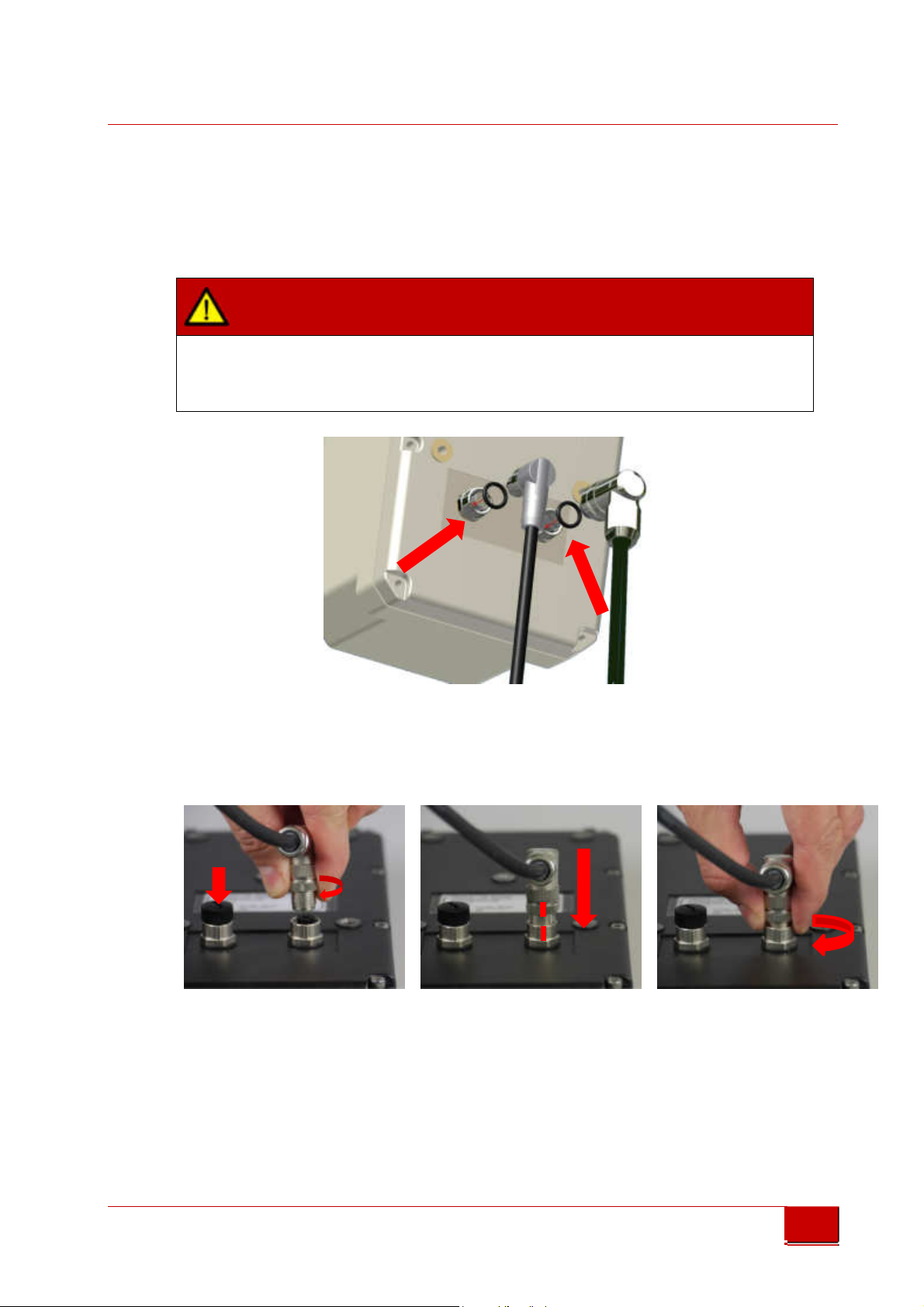
5.1 Phoenix SPEEDCON® quick locking System
low res. Internet brochure
low res. Internet brochure
ATTENTION
Before attaching the connectors, make sure the sealing rubber rings in the
sockets are all in place.
Always fit sealing connector caps onto plugs which are not used.
Picture 8: Connector rubber gaskets
PS Laser sensors are equipped with Pheonix SPEEDCON® M12 quick locking
connectors.
cap
Picture 9: Using the quick locking connectors
1. Make sure the rubber gaskets in the sockets are in place.
2. Turn the retainer ring until you notice a distinct „click“.
3. Align marks at the retainer ring and the socket.
4. Push the connector into the socket.
5. Turn the retainer ring to secure the connection.
© Triple-In GmbH • 11/01/2017 14:31:00
PSxxx-90 Laser Scanner User's Manual
13

Triple-IN
GmbH
5.2 Data and PoE Connector
5.2.1 Layout of the Data and PoE Connector
The Data and PoE Connector connects the sensor with the local network and
includes Power over Ethernet.
low res. Internet brochure
low res. Internet brochure
The Data and PoE Connector connects the sensor with the local network and
includes Power over Ethernet.
• M12 connector/ IP67/CAT6 connector
• Type Phoenix Contact
" Flush-type socket - SACC-CI-M12FS-8CON-L180-10G - 1402457"
• Adapter type reference is Phoenix Contact
" Bus system plug connector - VS-08-M12MR-10G-P SCO - 1417443".
• The pin/pair assignments conforms with the T568B standard
Picture 10: M12 Data and PoE scheme (plug side view)
Pin Signal Purpose
1. Tx+ Transmit
2. Tx- Transmit
3. Rx+ Receive
4. DC+ Positive supply voltage
5. DC+ Positive supply voltage
6. Rx- Receive
7. DC- Negative supply voltage
8. DC- Negative supply voltage
© Triple-In GmbH • 11/01/2017 14:31:00
PSxxx-90 Laser Scanner User's Manual
14

Triple-IN
GmbH
5.2.2 Power over Ethernet (PoE)
PS Laser Sensor uses the Power over Ethernet (PoE) technology. PoE systems pass
electrical power along with data on Ethernet cabling. This allows a single cable to
provide both data connection and electrical power.
The power lines on the serial interface become outputs if PoE is used. These
low res. Internet brochure
low res. Internet brochure
input/output lines are designed to provide power to an external turn table.
Picture 11 Scheme of the cross-linked power connectors
DANGER
Power supply
• Without heater: 24 Volt, 0.30 Ampere, 8 Watt
• With optional internal heater: 24 Volt, 1.25 Ampere, 30 Watt
To reduce the risk of electric shock and damages, only suitable PoE devices and
Ethernet cables specified for 30 Watt must be used. Note that IEEE
802.3af/Power over Ethernet Standards limit power to 12.95 Watt and PS Laser
Scanners will not meet this standard.
© Triple-In GmbH • 11/01/2017 14:31:00
PSxxx-90 Laser Scanner User's Manual
15

Triple-IN
GmbH
DANGER
Danger of a short circuit:
PoE and Serial interface connector are cross-linked.
The power lines on the serial interface become outputs if PoE is used.
low res. Internet brochure
low res. Internet brochure
The Ethernet interface of the control computer shall be protected by an
Ethernet Splitter to prevent short circuits if power is connected to the serial
interface connector.
Suitable PoE injectors and power supplies are offered by:
PHIHONG® USA
Model: POE31U-240 for 24 Volt/30 Watt
Available on www.digikey.com
Digikey part number: 993-1083-ND
5.3 Serial Interface Connector
5.3.1 Layout of the Serial Interface Connector
The PS Interface cable connects the control computer with the RS232 interfaces of
the Ethernet board and the measurement board.
The connector is type M12 connector/IEC 61076-2-101.
Picture 12: M12 Serial interface connector scheme (plug side view)
Pin
1 brown DC- Negative supply voltage Input
2 blue 24V DC+ Positive supply voltage Input
3 white GND 5 Volt Ground (RS232)
Color Signal Comment Direction
© Triple-In GmbH • 11/01/2017 14:31:00
PSxxx-90 Laser Scanner User's Manual
16
Triple-IN
GmbH
Pin
4 green 5V_IB 5 Volt DC output Do not connect
5 pink ORX RS 232 RxD Ethernet Board Input
6 yellow OTX RS 232 TxD Ethernet Board Output
7 black SWI4 Reserved for future use Output
8 gray SWI3 Reserved for future use Output
9 red 485A Reserved for future use Do not connect
low res. Internet brochure
low res. Internet brochure
10 purpur 485B Reserved for future use Do not connect
11 gray pink CH_A External incremental encoder input A Input
12 red blue CH_B External incremental encoder input B Input
13 white green CH_I Reserved for future use Do not connect
14 brown green SWI2 Digital switching output SW2 Output
15 white yellow SWI1 Digital switching output SW1 Output
16 yellow brown STD_RXD RS 232 RxD Measurement Board Input
17 white gray STD_TXD RS232 TxD Measurement Board Output
The color column refers to the layout of the optional “Serial interface cable”.
If Pin 1 and 2 are used for power supply, the Power-over-Ethernet connection
must be disconnected by use of a PoE splitter. Otherwise there can be a short
circuit in the Ethernet connector to the gateway.
Color Signal Comment Direction
ATTENTION
ATTENTION
In the table, any grey field is there for an expansion to a standard sensor. These
signals are required for special scanner versions
5.3.2 Power over the serial interface connector
The Serial interface connector includes 24 Volt power lines cross linked with the
PoE adapter. These input lines are designed to supply power over the serial
interface connector.
WARNING
Power supply
• Without heater: 24 Volt, 0.30 Ampere, 8 Watt
• With optional internal heater: 24 Volt, 1.25 Ampere, 30 Watt
© Triple-In GmbH • 11/01/2017 14:31:00
PSxxx-90 Laser Scanner User's Manual
17

Triple-IN
GmbH
5.3.3 Wiring the Measurement Board (MPU) RS232 Serial
Interface
The Serial Interface Connector includes RS232 to the the Measurement Board
(MPU).
The RS232 interface to the Measurement board (MPU) is used for system
low res. Internet brochure
low res. Internet brochure
configuration, e.g. to setup the network parameter.
PS Laser Sensors are classified as Data Terminal Equipment (DTE). According to the
standard, PS Laser Sensors shall be equipped with male connectors. A “null
modem cable” consisting only of “Transmit Data”, “Receive Data”, and “Ground”,
is commonly used since the full facilities of RS-232 are not required.
A DSUB9 connector must connect the following leads:
Picture 13 Measurement Board (MPU) DSUB9 male DTE pin layout (socket view)
Pin Color Signal Comment Direction
3 white GND 5 Volt Ground
16 yellow brown STD_RXD RS 232 RxD Measurement Board Input
17 white gray STD_TXD RS232 TxD Measurement Board Output
The color column refers to the layout of the optional “Serial interface cable”.
5.3.4 Wiring the Communication Board RS232 Serial Interface
The Serial Interface Connector includes the RS232 to the the Communication
Board (“Olimex”).
The Communication board provides the Ethernet interface. The RS232 interface is
only used for network status messages and for firmware updates of the
Communication board.
PS Laser Sensors are classified as Data Terminal Equipment (DTE). According to the
standard, PS Laser Sensors shall be equipped with male connectors. A “null
modem cable” consisting only of “Transmit Data”, “Receive Data”, and “Ground”,
is commonly used since the full facilities of RS-232 are not required.
Picture 14 Communication Board DSUB9 male DTE pin layout (socket view)
© Triple-In GmbH • 11/01/2017 14:31:00
PSxxx-90 Laser Scanner User's Manual
18

Triple-IN
GmbH
Pin Color Signal Comment
3 white GND 5 Volt Ground
5 pink ORX RS 232 RxD Communication Board Input
6 yellow OTX RS 232 TxD Communication Board Output
The color column refers to the layout of the optional “Serial interface cable”.
low res. Internet brochure
low res. Internet brochure
5.3.5 Wiring Digital Switching Outputs
The PS Laser scanner has two 5 Volt digital open-collector outputs, called SW1 and
SW2. These outputs can be programmed for different purposes:
• To give a scan synchronization signal
• As switch output, controlled by the connected computer
• As a preset counter, providing a programmable number of output signals.
Direction
Pin
1 brown DC- Ground
14 brown green SWI2 Digital switching output SW2 Output
15 white yellow SWI1 Digital switching output SW1 Output
The color column refers to the layout of the optional “Serial interface cable”.
© Triple-In GmbH • 11/01/2017 14:31:00
PSxxx-90 Laser Scanner User's Manual
Color Signal Comment
Picture 15 Digital output wiring scheme
Direction
19

Triple-IN
GmbH
5.3.6 Wiring an External Incremental Encoder
The PS Laser Scanner provides one 3.3 to 5.0 Volt incremental encoder input.
Purpose of the external incremental encoder is to report changes in the horizontal
position of the sensor.
The incremental encoder must provide two pulses A and B. The PS Sensor
low res. Internet brochure
low res. Internet brochure
firmware counts these pulses in both directions by use of a 32 bit register.
Input is limited to 128.000 counts/second.
Reset of the counter is done at startup or by software.
Picture 16 Incremental encoder wiring scheme
Pin
1 brown DC- Ground
3 white GND 5 Volt Ground (RS232)
11 gray pink CH_A External incremental encoder input A Input
12 red blue CH_B External incremental encoder input B Input
The color column refers to the layout of the optional “Serial interface cable”.
Color Signal Comment
Direction
© Triple-In GmbH • 11/01/2017 14:31:00
PSxxx-90 Laser Scanner User's Manual
20

6 Setting into Operation
6.1 Windows® Software Tools
Triple-IN
GmbH
low res. Internet brochure
low res. Internet brochure
6.1.1 Windows Program TeraTerm for the RS232 Serial Interface
TeraTerm, written by T. Teranishi, is a very suitable program for the so-called
Terminal Mode of the PS Laser Scanner. TeraTerm is a free software terminal
emulator (serial communication program) for Windows. The program is available
on Triple-IN’s webserver. Any other terminal program will be suitable as well.
1. Download TeraTerm from Triple-IN’s webserver.
2. Run the TeraTerm program installer.
3. Connect the EDM via a RS232 connection, using either a generic COM port or
an USB-to-serial adapter.
4. Open TeraTerm and navigate to "Setup > Serial port..."
5. Choose the correct COM port.
6. Set the baud rate to 115200, 8 data bits, no parity, 1 stop bit, no flow control.
7. Close the setup dialog.
8. If you want to store these settings for future use, go to "Setup > Save setup…"
9. Navigate to the TeraTerm installation directory and store the setup in
TERATERM.INI.
© Triple-In GmbH • 11/01/2017 14:31:00
PSxxx-90 Laser Scanner User's Manual
21

Triple-IN
GmbH
6.1.2 Windows® Program “TCP/IP Manager” to manage
Network Configurations
Triple-IN recommends the open-source Freeware “TCP/IP Manager” (author: A. C.
Tundrea) to prepare the computer’s network settings for PS Laser Sensors. With
the tool, you may simply save and restore network settings for PS Laser Scanners
low res. Internet brochure
low res. Internet brochure
and standard Windows applications in different profiles.
1. Download TCP/IP Manager from Triple-IN’s webserver.
2. Run the installer resp. unpack the ZIP file.
3. Start TCP/IP Manager.
4. Select in “TCP/IP Settings > Network connection name” the network
adapter connected with the PS Laser Sensor.
5. Check if “IP address” matches the Gateway IP address as stored in the PS
Laser Sensor. The default Gateway address is 10.0.10.0.
6. Check if “Subnet mask” matches the subnet mask as stored in the PS Laser
Sensor. The default network mask is 255.255.0.0.
7. For later use, consider “Network profile > Create a new profile” to save the
setup.
8. Choose “Apply Settings”.
9. To connect a PS Laser Sensor with the default settings:
Picture 17 Network configuration for PS Laser Sensors with TCP/IP Manager
© Triple-In GmbH • 11/01/2017 14:31:00
PSxxx-90 Laser Scanner User's Manual
22

Triple-IN
GmbH
After disconnecting the sensor, you may use TCP/IP Manager to restore the
Windows standards:
low res. Internet brochure
low res. Internet brochure
Picture 18 Restore the Network configuration with TCP/IP Manager
1. Start TCP/IP Manager.
2. Select in “TCP/IP Settings > Network connection name” the network
adapter connected with the PS Laser Sensor.
3. “Obtain an IP address automatically” should be checked.
4. For later use, consider “Network profile > Create a new profile” to save the
setup.
5. Choose “Apply Settings”.
6.1.3 Triple-IN’s PSControlProgram
Triple-IN’s PSControlProgram is a PC application for controlling the functionality of
Triple-In Laser sensors via Ethernet connection. It makes the user able to set the
user parameters of the sensor, start measurements, record the scans to files or
show it on the chart or in the table.
The program is available on Triple-IN’s webserver.
To install the application please follow the instructions:
© Triple-In GmbH • 11/01/2017 14:31:00
PSxxx-90 Laser Scanner User's Manual
23

Triple-IN
GmbH
1. Start Windows installation program “Install_PSControlProgram.exe”.
2. Confirm that you have administrator permissions to install the program.
3. The installer inspects the version information in order to use it during the
installation process.
4. The product information (company, product name and version) is displayed
on the screen if it's found during the analysis process.
low res. Internet brochure
low res. Internet brochure
5. Confirm installation.
A full description of the program can be found in the “of PSControlProgram User’s
manual”. The manual is part of the program distribution.
6.2 Power-up
To start the system:
• Connect the control computer to the same network of the PS Laser Scanner.
• Connect the power supply to the PS Laser Scanner
• After switching on the supply voltage the scanner runs through a self-test. All
LEDs are flashing. The firmware of the device checks important hardware
components and parameters. Commands will respond to the control computer
with a "device not ready" error.
• The red LED is switched off after the self-test has passed successfully.
ATTENTION
After disconnecting the sensor from power supply, you have to wait 30 seconds
before turning it on. Otherwise capacitors not being discharged could leave the
sensor peripheral not fully reset
6.3 Serial RS232 communication
6.3.1 Setting up the serial Communication
PS Laser Scanners have serial RS232 interfaces to connect a control computer with
the measurement board. A second RS232 can be connected to the Ethernet board
to allow firmware updates. The standard communication settings are:
• RS232 Serial input/output
• Baud rate 115.200 Baud,
• Data 8 data bit,
© Triple-In GmbH • 11/01/2017 14:31:00
PSxxx-90 Laser Scanner User's Manual
24

Triple-IN
GmbH
• no parity, 1 stop bit,
• no flow control, no handshake
The first serial interface, internally connected with the Measurement board
(MPU), is used to program the TCP/IP connection parameters and to update the
Measurement board firmware. This interface supports the so-called Terminal
Mode (see chapter "Terminal Mode"). After startup displays the terminal the
low res. Internet brochure
low res. Internet brochure
sensor's serial number, IP address and self-test results.
Picture 19: TeraTerm with Measurement Board startup message
The second serial interface is connected with the communication board and is
used for Ethernet firmware updates only (see chapter "Firmware updates"). It
displays the current Ethernet board firmware version and a connection status.
Picture 20: TeraTerm with Communication board startup message
© Triple-In GmbH • 11/01/2017 14:31:00
PSxxx-90 Laser Scanner User's Manual
25

Triple-IN
GmbH
6.3.2 Entering the Terminal Mode
The PS Laser Scanner provides a Terminal Mode as an additional user interface.
This is an ASCII oriented, human-readable menu structure and user interface
available on the RS232 serial interface.
The Terminal mode is entered after the user sends 4 successive carriage return
low res. Internet brochure
low res. Internet brochure
characters from a RS232 terminal console.
Note
The Ethernet interface is not available while the sensor operates in the Terminal
Mode.
________________________________________________________________________
Terminal Mode
________________________________________________________________________
1 - Show user parameter
2 - Show system health status
3 - Network configuration...
4 - Restore to factory settings
5 - Show reference tables...
E - Edit parameter
S - Take a scan
L - Switch laser marker
0 - Exit to Run Mode
>
Show user parameter
Lists the parameters set by the user. With the function "Edit parameter" these
values can be edited.
Show system health status
List the results of the self-test.
Network configuration
Change the IP settings to standard configurations.
Restore to factory settings
This function is used to set parameters to their default values.
© Triple-In GmbH • 11/01/2017 14:31:00
PSxxx-90 Laser Scanner User's Manual
26

Triple-IN
GmbH
IMPORTANT
All changed user parameters will get lost.
Show reference tables
Display the firmware versions and parameter code reference tables.
low res. Internet brochure
low res. Internet brochure
Edit parameters
This function is used to change any parameter. The parameter codes are needed
for this. After entering the parameter code the firmware shows the current value,
the measurement unit and the valid range of values. The program then asks
whether the changed parameters should be stored in the flash.
> E
> Enter parameter ID:
3_
> Enter parameter "Scan mode: 0=off, 1=normal, 2=fast, 3=fine":
2_
Take a scan
Starts the motor and carries out a single scan. The result is presented as CVS table.
This function shall be used to check the basic functionality of the sensor.
Switch laser marker
Switch the red laser marker on and off.
6.3.3 Binary Command/Control Interface
Control computer programs, such as PSControlProgram, communicate with PS
Laser Scanners over Ethernet or serial RS232 by use of binary commands. A full
reference of the binary command/control interface can be found in the “PS Laser
Scanner Programmer’s Manual”.
IMPORTANT
Avoid communicating with the PS Laser Sensor via Ethernet and RS232 at the
same time. The commands can influence each other and may lead to
unpredictable system states.
© Triple-In GmbH • 11/01/2017 14:31:00
PSxxx-90 Laser Scanner User's Manual
27

Triple-IN
GmbH
6.4 Ethernet Connection
6.4.1 PS Laser Scanner Network Settings
PS Laser scanners use the Internet Socket Interface for communications over
Ethernet.
low res. Internet brochure
low res. Internet brochure
The sensor socket address is the combination of an IP address (the location of the
sensor) and a port (which is mapped to the application program process) into a
single identity.
The transport protocol UDP assumes that error checking and correction is
performed in the application by checking the CRC that comes with the sensor
command structure. This avoids the overhead of such processing at the network
interface level. As a time-sensitive application use the firmware UDP because
dropping packets is preferable to waiting for delayed packets.
• Type: 100 MBit/s Local area network
• Network layer Ethernet IPv4
• Transport Protocol UDP
• Application Protocol Binary Command Interface
• Sensor IP address 10.0.xx.xx
where x is formed by the sensor serial number
• Server socket port 1024 (factory pre-setting)
• Gateway IP address 10.0.10.0 (factory pre-setting)
• Gateway socket port 1025 (factory pre-setting)
IMPORTANT
The sensor replies to any computer in the same IP address space.
The Gateway IP address is used as default.
The MAC address of the scanner is locally administered by setting the secondleast-significant bit of the most significant byte (the so-called U/L bit, short for
Universal/Local). That address bit is 1, the address is locally administered and
the sensor might be used in local networks only.
© Triple-In GmbH • 11/01/2017 14:31:00
PSxxx-90 Laser Scanner User's Manual
28

Triple-IN
GmbH
6.4.2 Changing the Sensor’s Network Settings using the RS232
Terminal Mode
The sensor IP address and the Gateway IP address can be set in the RS232
Terminal Mode with the parameters “Sensor IP address”, “Gateway IP address”,
and “IP Subnet Mask”.
low res. Internet brochure
low res. Internet brochure
The Terminal Mode includes a function “3 - Network configuration ...” for a simple
IP setup. The following configurations are available and can be changed
individually:
______________________________________________________________________________
Network configuration menu
Sensor IP address is 10.0.8.01
Gateway IP address is 10.0.10.0
______________________________________________________________________________
1 - Set default sensor IP address
2 - Set static sensor IP address
3 - Set private sensor address (APIPA)
4 - Edit sensor IP address
5 - Edit Gateway IP address
6 - Edit network mask
0 - Exit
• Default sensor IP address which is created in address space 10.0.x.x
according to the sensor serial number.
• A static sensor IP address which is 192.168.0.10 by default.
• Private sensor IP address (APIPA) which is 169.254.0.10 by default.
APIPA addresses are by standalone Windows computers.
These IP settings can be changed individually after the default has been set:
> Enter Parameter “Sensor IP Address AAA.xxx.xxx.xxx”:
192
> Enter parameter “Gateway IP Address xxx.BBB.xxx.xxx”:
168
[…]
© Triple-In GmbH • 11/01/2017 14:31:00
PSxxx-90 Laser Scanner User's Manual
29

Triple-IN
GmbH
IMPORTANT
• The sensor need to be restarted after IP addresses has been changed.
• The Ethernet interface is disabled while the Terminal mode is active.
low res. Internet brochure
low res. Internet brochure
6.4.3 Changing the Sensor’s Network Settings using
PSControlProgram
PSControlProgram is useful to change the sensors’s default network settings over
Ethernet:
1. Start PSControlProgram.
2. Choose button “Connect” to connect the application with a sensor. The IP
and port dialog appears on the beginning of the connection progress.
3. Enter the sensor’s standard IP address and the computer’s IP address. Note
that both addresses must be part of the same network.
Picture 21 PSControlProgram network connection dialog
4. Once the connection has been made, all parameters including the network
settings can be changed on the “Parameters” view.
© Triple-In GmbH • 11/01/2017 14:31:00
PSxxx-90 Laser Scanner User's Manual
30

Triple-IN
GmbH
low res. Internet brochure
low res. Internet brochure
Picture 22 PSControlProgram Parameter view
5. Switch-off and restart the sensor to apply the changed network settings.
6.5 PS Laser Scanner Configuration
6.5.1 Ways of Configuration
You can configure the PS Laser Scanner in two ways:
• Using the commands “GPRM get parameter” and “SPRM set parameter” of
the binary command/control interface. This way is most suitable for
computer programs, such as PSControlProgram
• interactively using the RS232 Terminal Mode
6.5.2 About User Parameters
The entire sensor configuration is stored in a table of user parameters. Every
parameter has a number as unique parameter identification code. The user can
© Triple-In GmbH • 11/01/2017 14:31:00
PSxxx-90 Laser Scanner User's Manual
31

Triple-IN
GmbH
edit the parameter either by use of the Terminal Mode, or over RS232 and
Ethernet by use of binary commands.
ATTENTION
Parameter identifiers always refer to a certain firmware version. Therefore an
low res. Internet brochure
low res. Internet brochure
individual parameter reference table exists for every firmware version.
You find the description of the binary commands for the processing of the user
parameters in the “PS Laser Scanner Programmer’s Manual”.
There are different types of parameter:
• Usual parameters can be set by the user for sensor configuration. Those
parameters are stored in the non-volatile memory of the sensor.
•
Constant parameters
user.
•
Temporary parameters
a device status has been changed. Note that temporary parameters are
typically updated by a self-test during the startup phase. It is
recommended to set temporary parameters only after the self-test has
been finished.
(e.g. the serial number) cannot be changed by the
(e.g. the system temperature) will be overwritten if
© Triple-In GmbH • 11/01/2017 14:31:00
PSxxx-90 Laser Scanner User's Manual
32

6.5.3 Table of User Parameters
ID Default
Name Description
A version number of the parameter set
The terminal mode can be protected by a password
This parameter defines
the operating scan mode:
If this parameter is 1, the scanner provides a continuous
If this parameter
was set to 1, the scanner enters the
If this parameter was set to 1, the startup messages like
If this parameter was set to 1, the red laser marker is
Temporary parameter
indicating the current status of the
A constant that defines the angle unit.
Defines the size of the scan angle and the scan area.
Defines the start direction of the scans.
Defines the angle between two measurements in a scan.
Each of four subsequent scans is shifted by
this angle. Only
Contains the local IP address of the sensor
Contains the local IP address of the sensor
Contains the local IP address of the sensor
Contains the local IP address of the sensor
IP Socket number of the sensor
Contains the Gateway IP
address of the control computer
Contains the Gateway IP address of the control computer
Contains the Gateway IP address of the control computer
Contains the Gateway IP address of the control computer
Contains the socket number at the control computer
Triple-IN
GmbH
1 20160112 Const: User
2 0 User parameter
low res. Internet brochure
low res. Internet brochure
3 0 Scan mode:
4 0 Auto-start without
5 0 Start mode,
6 1 Startup message on
7 1 Red Laser Marker at
8 1 Temp: Red Laser
9 360000 Const: Angle units
10 90000 Scan angle size
11 45000 Profile scan start
12 90 Const: Scan a ngle
13 0 Const: Sc an angle
14 10 Sensor IP Add ress
15 0 Sensor IP Address
16 1 Sensor IP Address
17 23 Sensor IP Add ress
18 1024 Sensor socket port
19 10 Gateway IP Ad dress
20 0 Gateway I P Address
21 10 Gateway IP Ad dress
22 0 Gateway I P Address
23 1025 Gateway socket port
settings
password,
0=disabled
off=0,
normal=1,
fast=2,
fine=3
SCAN/GSCN command,
enabled=1,
disabled=0
0=Standard,
1=Terminal Mode
serial interface,
enabled=1
startup:
off=0,
on=1,
auto=2
Marker status:
off=0, on=1
on a full circle
[0.001 deg]
direction
[0.001 deg]
step [0.001 deg]
shift [0.001 deg]
AAA.xxx.xxx.xxx
xxx.BBB.xxx.xxx
xxx.xxx.CCC.xxx
xxx.xxx.xxx.DDD
AAA.xxx.xxx.xxx
xxx.BBB.xxx.xxx
xxx.xxx.CCC.xxx
xxx.xxx.xxx.DDD
number.
Enter "0" to disable the password
fine/normal/fast.
output stream of profiles
Terminal mode after startup.
the firmware version are not displayed on the serial
interface.
switched after startup.
Set to 0 if you wish the red laser marker to be off after
startup.
red laser marker.
used by the “Fine Mode”.
© Triple-In GmbH • 11/01/2017 14:31:00
PSxxx-90 Laser Scanner User's Manual
33

Triple-IN
ID Default
Name Description
Defines the IP sub
-
net mask of the local sensor network.
Defines the IP sub
-
net mask of the local sensor network.
Defines the IP sub
-
net mask of the local sensor network.
Defines the IP sub
-
net mask of th
e local sensor network.
The number of different echoes the sensor is able to
Defines the
master echo.
Defines how many scans shall be buffered. This parameter
Defines the data transmitted with the GSCN command.
Number of scans to be
stored in the internal buffer
This offset is added to all distances.
This parts
-
per-million correction is applied to all distances.
The heater is switched on if the internal temperature is
The heater is switched off i f the internal temperature is
Temporary parameter containing the curre
nt status of the
If set to “0”, the motor is stopped after the sensor has
Temporary
parameter containing the current status of the
The optional incremental encoder input is enabled if this
This param
eter contains the offset of the external
GmbH
24 255 IP Sub-net mask
25 255 IP Sub-net mask
26 0 IP Sub-ne t mask
27 0 IP Sub-ne t mask
28 1 Const: Nu mber of
low res. Internet brochure
low res. Internet brochure
29 1 Master ec ho:
30 4 Temp: Num ber of
31 8 Scan data content:
32 14 Scan buffer size;
33 0 User defi ned
34 0 Const: Us er defined
35 150 Air condition
36 200 Air condition
37 0 Temp: Air condition
38 1 Vertical motor at
39 1 Temp: Ver tical
40 0 External
42 0 External
AAA.xxx.xxx.xxx
xxx.BBB.xxx.xxx
xxx.xxx.CCC.xxx
xxx.xxx.xxx.DDD
multi-echos
1=first, 0=last
profiles to be
measured with SCAN
4=distances,
7=distance+Echo+PW
8=distances+PW
distance offset
[0.1 mm]
ppm correction
[mm/km]
heater ON threshold
[0.1 celsius]
heater OFF
threshold [0.1
celsius]
heater status,
off=0, on=1
startup, off=0,
on=1
motor status,
1=running
incremental
encoder: enabled=1,
disabled=0
incremental
encoder: offset
output. Constantly 1, because either the first echo or
alternately the last echo is provided.
If the parameter is set to “1” the closest target is
measured.
If the parameter is set to “0”, the fu rthest target is
measured.
is set by the SCAN command.
The parameter is equal with the number of bytes
transferred for each echo:
4: only distances are transmitted (4 bytes)
7: distance (4 bytes), echo number (1 byte), and pulse
widths are transmitted.
8: distances (4 bytes) and pulse widths (4 bytes) are
transmitted
Other values may lead to unexpected results.
below this threshold.
Note that the internal temperature is about 15° Celsius
above ambient temperature.
above this threshold.
The heater is always switched on if the temperature is
below the operating range.
heater.
passed the self-test.
The motor is restarted by the first SCAN command.
vertical motor.
parameter was set to 1.
incremental encoder.
© Triple-In GmbH • 11/01/2017 14:31:00
PSxxx-90 Laser Scanner User's Manual
34

Triple-IN
ID Default
Name Description
This parameter contains the current reading from the
Bit map that reflects the system health. Invalid if bit 0 is
Reserved for future use.
If this parameter was set on 0, the front LEDs flash only at
Current reading of the temperature sensor in 0.1 Celsius
Constant parameter, containing the pulse width in
Constant parameter, containing the pulse width in
Sensor model number to identify the type of sensor
Sensor seria
l number
Gives information about the actual near field dimension.
Defines the near field suppression zone. Each zone extends
Programs the function of the digital switching output 1:
Current logical status of the discrete output switch 1
Number of signals to be output if digital output switch 1
"Holds" digital switching output 1 for the given
Requires a sensing event to last for at least the given
Defines the physical logic of digital switching output 1:
Programs the function of the digital switching output 2:
Current logical status of digital switching output 2
Number of signals to be output if digital switching output 2
"Holds" digital switching output 2 for the given
Requires a sensing event to last for at least the given
GmbH
42 0 Temp: Ext ernal
43 0 System he alth
44 0 (reserved )
45 1 Front sid e LEDs
low res. Internet brochure
low res. Internet brochure
46 368 Const: Temperature
47 12000 Const: Pulse width
48 4096 Const: Pulse width
49 2025 Const: Sensor
50 1234 Const: Sensor
51 21000 Const: Near field
52 0 Near fiel d
53 1 SW1 funct ion:
54 0 Temp: SW1 status:
55 0 Temp: SW1 preset
56 20 SW1 hold time [ms]
57 20 SW1 delay [ms ]
58 0 SW1 logic :
59 0 SW2 funct ion:
60 0 Temp: SW2 status:
61 0 Temp: SW2 preset
62 20 SW2 hold time [ms]
63 20 SW2 delay [ms ]
incremental
encoder: counts
status
enabled=1,
disabled=0
sensor reading [0.1
celsius]
at 100% signal [ps]
at 3% signal [ps]
model;
serial number
suppression range
[0.1 mm]
suppression zone:
0=min
0=off, 1=scan sync,
2=switch, 3=counter
0=open 1=closed
counter: setup
0=normal, 1=low
active
0=off, 1=scan sync,
2=switch, 3=counter
0=open 1=closed
counter: setup
external incremental encoder.
set.
the start and be turned off then.
picoseconds related to a signal of 100%.
picoseconds related to a signal of 3%.
the near field for about 0.8 m.
1=SW is closed while a scan is active
2=SW is closed if parameter "SW status" is set to 1
3=SW is used as a preset counter
was configured as preset counter.
milliseconds after the input signal is removed.
Allows the control device to igno re intermittent signal
losses.
milliseconds before digital switching output 1 is switched.
Allows the control device to igno re short sensing events.
0=SW is high active, 1=SW is low active.
1=SW is closed while a scan is active
2=SW is closed if parameter "SW status" is set to 1
3=SW is used as a preset counter
was configured as preset counter.
milliseconds after the input signal is removed.
Allows the control device to igno re intermittent signal
losses.
milliseconds before digital switching output 2 is switched.
Allows the control device to igno re short sensing events.
© Triple-In GmbH • 11/01/2017 14:31:00
PSxxx-90 Laser Scanner User's Manual
35

Triple-IN
ID Default
Name Description
Defines the physical logic of digital switching output 2:
If the laser spot is only partly reflected by object edges,
If the laser spot is
reflected by several surfaces, incorrect
Parameter without function.
User parameters
are stored the volatile memory.
GmbH
64 0 SW2 logic :
65 0 Low echo filter:
66 1 High echo filter:
low res. Internet brochure
low res. Internet brochure
67 0 User para meter ID
68 0 Temp: Mem ory write
0=normal, 1=low
active
0=disabled,
1=enabled
0=disabled,
1=enabled
used for testing
protection,
1=locked
0=SW is high active, 1=SW is low active.
incorrect measuring arises. This filter removes
measurements with very low echo signals.
measurements arise. This filter removes measurements
with very strong echo signals.
Setting this parameter to “0” prevents the firmware to
write parameters to the flash.
6.6 Taking Scans
6.6.1 Setting up the Scan mode
PS Laser Scanners can operate in “normal scan mode”, “fast scan mode”, or “fine
scan mode”. Scan modes are set by binary commands or by use of the Terminal
mode. The scan mod can be set with the user parameter:
Scan mode: 0=off, 1=normal, 2=fast, 3=fine
With each of the scan modes, the following measurement parameters are set:
• Scan rate: Number of scans per second.
• Scan start direction: direction of the first measurement point of a scan.
• Scan angle: size of the scan area in degree.
• Scan angle step: small angle between two subsequent measurement points.
Defined by the scan angle size and the number of measurement points.
• Scan Angle Shift: small angle between the start directions of subsequent scans.
Normal scan mode
The „Normal Scan Mode” is defined by the following parameters:
• Scan rate: 20 scans per second.
• Scan start direction: min. 45°
• Scan angle: max. 90° with 1000 points.
• Scan angle step: 90°/1000 points = 0.090°
• Scan Angle Shift: Normal-Mode scans are not shifted.
© Triple-In GmbH • 11/01/2017 14:31:00
PSxxx-90 Laser Scanner User's Manual
36

Triple-IN
GmbH
Fast scan mode
For increasing the scan rate the point density has to be reduced. In „Fast Scan
Mode” the point density is halved, the scan rate is doubled and the “profile rate”
reduced accordingly.
• Scan rate: 40 scans per second.
• Scan start direction: min. 45°
low res. Internet brochure
low res. Internet brochure
• Scan angle: max. 90° with 500 points.
• Scan angle step: 90°/500 points = 0.180°
• Scan Angle Shift: Fast-Mode scans are not shifted.
Fine scan mode
If the scan rate is not important but the lateral resolution is the important
parameter, the shift of the scans may be reduced. This leads to more
“scans/profile” and consequently to a better lateral resolution with overlapping
spots and a reduced profile rate. This measurement mode is called “Fine Scan
Mode”.
• Scan rate: 20 scans per second
• Profile rate: 5 profiles per second
• Scan start direction: min. 45°
• Scan angle: max. 90° with 1000 points.
• Profile angle: max. 90° with 3000 points interlaced.
• Scan angle step: 90°/1000 points = 0.090°
• Profile angle step: 90°/3000 points interlaced = 0.0225°
Scan Angle Shift: Each scan is shifted by 0.0225°. Subsequent scans are interlaced
to a single profile.
Reserved scan mode
Option for customized scanners. Do not use this scan mode with standard PSxxx90 Laser scanners.
6.6.2 Taking Scans with the Terminal Mode
The Terminal Mode function “Take a scan” creates a table with the latest profile
scan. The ASCII format is "comma separated" and can easily use Excel or Open
Office.
1. Enter the Terminal Mode
2. Open in TeraTerm "File > Log...". Check "Plain text" and disable "Append"
© Triple-In GmbH • 11/01/2017 14:31:00
PSxxx-90 Laser Scanner User's Manual
37

Triple-IN
GmbH
3. Choose a log file name and close the dialog. Teraterm will now record all
sensor outputs.
4. Choose "S – Take a Scan"
5. Close TeraTerm
6. The log file can be opened directly with a common spread sheet program
low res. Internet brochure
low res. Internet brochure
like Excel or OpenOffice Calc.
Scan;
______________________________________________________________________________
375.877; Time Stamp [s] ;
0; Incremental encoder position [counts];
45.000; Profile start direction [deg];
90.000; Scan angle [deg];
0.090; Angle step [deg];
1000; Points in profile ;
0; Master echo (0=last echo);
1; Number of echoes;
31.7; Temperature [Celsius];
______________________________________________________________________________
Point ; Echo ; Direction ; Distance ; Pulse width ;
; ; [deg] ; [m] ; [ps] ;
______________________________________________________________________________
1 ; 1 ; 45.000 ; 2.4388 ; 9907 ;
2 ; 1 ; 45.090 ; 2.4305 ; 9895 ;
3 ; 1 ; 45.180 ; 2.4340 ; 9871 ;
4 ; 1 ; 45.270 ; 2.4437 ; 9772 ;
[…]
1000 ; 1 ; 314.910 ; 1.6629 ; 6465 ;
The header of the table contains
• Time stamp [s]: is the time in seconds since the sensor was started
• Incremental encoder position [count]: is the count of the external
incremental encoder.
• Profile start direction: is the start direction of the profile, where 0 is
upwards to the zenith.
• Scan angle: is the scanned area in degrees.
• Angle steps: give the scan resolution in degrees.
• Points in profile: give the length of the following table.
• Master echo: 1 for the first echo or 0 for the last echo.
• Number of echoes: the number of echoes processed.
© Triple-In GmbH • 11/01/2017 14:31:00
PSxxx-90 Laser Scanner User's Manual
38

Triple-IN
• Temperature: is the reading from the internal temperature sensor in
Celsius.
The measurement table contains
• Point: the number of the current point in the scan
GmbH
low res. Internet brochure
low res. Internet brochure
• Echo: the number of the evaluated echo. This value is always 1 if the
Master Echo parameter has been set to “1=first echo”. The echo number
varies from 1 to 4 if the Master Echo has been set to “0=last echo”.
• Direction: direction to the target in degree.
• Distance: distance in meters to the target surface.
• Pulse width : echo signal pulse width in pico-seconds
6.6.3 Taking Scans with Triple-IN’s PSControlProgram
Triple-IN’s PSControlProgram is a Windows application with user menu, toolbar,
status line, workspace explorer bar and the data output widgets ordered in the
tabs. User menu and main toolbar are providing the basic functionality for the
system actions like connecting the program with a sensor, performing the scans,
recording, loading or, exporting the data to “*.csv” files.
1. Connect to the PS Laser Sensor
© Triple-In GmbH • 11/01/2017 14:31:00
PSxxx-90 Laser Scanner User's Manual
39

Triple-IN
GmbH
2.
Once online the record button allows the user to write the scans to the
binary files for later evaluation.
3. If the recording starts successfully the application starts to write the binary
data to files. Every minute the new file for recorded files is created.
4. To find the easily files easily press “Open output directory” button on the
toolbar and windows
low res. Internet brochure
low res. Internet brochure
6.7 Filters and Master Echo selection
6.7.1 Near-field suppression
The near-field suppression is used to suppress measurements to targets close to
the sensor. This prevents the sensor to detect contamination of the optics.
PS Laser Scanners have optional, adjustable near-field suppression. This is divided
up in zones, each with a width of 760 millimeter. Zone 0 defines the closest
distance. The closest distance depends on the PS Senor type.
The near field suppression zone can be configured with the user parameter:
Near-field suppression zone, min=0
The current near field range can be obtained by the parameter
Const: Near field suppression range [0.1 mm]
© Triple-In GmbH • 11/01/2017 14:31:00
PSxxx-90 Laser Scanner User's Manual
40

Triple-IN
GmbH
low res. Internet brochure
low res. Internet brochure
Picture 23 Near-field configuration, example with zone 3
Example:
1) Echoes of targets in Zone 0 are always ignored and not detected by the
laser receiver.
2) In this example was zone 3 has set as near field zone. The target in this
range is ignored. The near-field range is calculated as
Near_field_range = zone0 + zone1 + zone2 + zone3
Any echo in this range will be ignored.
3) Echoes of targets beyond the near-field range give valid echoes.
6.7.2 Low echo filter
If the laser spot is only partly reflected by object edges, incorrect measurements
may arise. A “low echo filter” removes measurements with echo signals less than
© Triple-In GmbH • 11/01/2017 14:31:00
PSxxx-90 Laser Scanner User's Manual
41

Triple-IN
GmbH
3%. To use the full range of sensitivity, the low echo filter can be disabled. The
user parameter must be set to 0:
Low echo filter; 0=disabled, 1=enabled
low res. Internet brochure
low res. Internet brochure
6.7.3 High echo filter
If the laser spot is reflected by several surfaces, incorrect measurements may arise
due to deformations of the echo signal. The “high echo filter” removes
measurements which appear with very wide echo signal amplitudes.
The high echo filter can be disabled to allow measurements on reflectors and
reflecting foil. The user parameter must be set to 0:
High echo filter: 0=disabled, 1=enabled
6.7.4 Master Echo selection
At measuring through rain, through protection windows, or in dusty surroundings
several objects may reflect the laser beam. The echo of the actual measuring
target is called “Master Echo”.
Picture 24 Multi-Echo with Master Echo selection
© Triple-In GmbH • 11/01/2017 14:31:00
PSxxx-90 Laser Scanner User's Manual
42

Triple-IN
GmbH
PS Laser scanners can handle the first or the last one of up to 4 echoes as "Master
Echo". For configuration the user parameter “Master echo” is used:
Master echo: 1=first, 0=last
• Scans contain the first echo (closest object) if the parameter has been set to
low res. Internet brochure
low res. Internet brochure
“1”.
• If the parameter is set to “0”, the furthest measuring is evaluated.
6.7.5 Alternating Master Echo
Some applications require measurements to the first and the last echo. The
master echo configuration can be set to alternate with each scan. With every new
Scan the master echo changes between "first echo" and "last echo" to support this
requirement.
For alternating master echo configuration the following user parameters are used:
Number of registered echoes: 2
Master echo: 0=last
• The “Number of registered echoes” defines the echoes to be captured.
Always the same echo (first or last) is taken if the parameter was set to 1. If
set to 2 allows to capture alternating echoes.
• The parameter “Master echo” must always be set to “0=last echo” for
alternating master echoes.
6.8 Setting up the Digital Switching Outputs
PSxxx-90 Laser Scanners have two digital outputs. These outputs can be
programmed for different purposes:
• To give a scan synchronization signal
• As switch output, controlled by the connected computer
• As a preset counter, providing a programmable number of output signals.
© Triple-In GmbH • 11/01/2017 14:31:00
PSxxx-90 Laser Scanner User's Manual
43

Triple-IN
GmbH
6.8.1 Using a digital output for scan synchronization signals
One digital output can be configured to provide a scan synchronization signal. The
signal is set high while the measuring laser is active during a scan. The signal is
cleared during the idle period between two scans.
Only one of the digital outputs can be used for the synchronization signal.
low res. Internet brochure
low res. Internet brochure
Changing the synchronization output port will leave the previous synchronization
output port inactive.
The feature is set active by setting the parameter “SW function” to “1=scan sync”:
SWn function: 1=scan
6.8.2 Setting the status of a digital switching output
The state of the digital switching outputs can be set by software. This allows a
control computer to signal application depending status information to another
system.
The feature is set active by setting the parameter “SW function” to “2=switch”.
The open/closed status of the output is set by the user parameter:
SWn function: 2=switch
SWn status: 0=open, 1=closed
6.8.3 Using a digital switching output as preset counter
User applications can set a counter value in advance to produce output signals of
a specific count. This function permits a control computer to transmit a counting
stand or volume information as digital signals to another system. All digital
switching outputs can be used independently. The preset counter feature is set
active by setting user parameter “SW function” to “3=counter”.
The counter value must be written to the parameter
SWn function: 3=counter
SWn preset counter: setup
The sensor firmware copies this value, sets the parameter register back to 0, and
starts the countdown. After this, new counts can be added to current output by
writing another counter value. Make sure that the parameter “SW preset counter
setup” has reached 0 before adding new counts.
The hold time can be defined by the user parameter
© Triple-In GmbH • 11/01/2017 14:31:00
PSxxx-90 Laser Scanner User's Manual
44

Triple-IN
GmbH
SWn hold time [ms]
The delay between counter signals can be defined by the user parameter
SWn delay [ms]
low res. Internet brochure
low res. Internet brochure
The resolution of both timing parameters is about 10 ms.
Example
The parameter setup
53; 3; SW1 function: 0=off, 1=scan sync, 2=switch, 3=counter;
56; 10; SW1 hold time [ms];
57; 20; SW1 delay [ms];
58; 0; SW1 logic: 0=normal, 1=low active;
59; 3; SW2 function: 0=off, 1=scan sync, 2=switch, 3=counter;
62; 30; SW2 hold time [ms];
63; 40; SW2 delay [ms];
64; 1; SW2 logic: 0=normal, 1=low active;
In conjunction with the counter parameters
55; 4; Temp: SW1 preset counter: setup;
61; 2; Temp: SW2 preset counter: setup;
Results in the following signal pattern:
© Triple-In GmbH • 11/01/2017 14:31:00
PSxxx-90 Laser Scanner User's Manual
45

Triple-IN
GmbH
Picture 25 Digital switching output example signal pattern
6.9 Controlling the Heater (optional)
PS Laser Scanners for outdoor applications can optionally be equipped with an
th
internal heater. Temperature parameters are handled in 10
low res. Internet brochure
low res. Internet brochure
“312” are 3.12°C.
The switching points of the heater can be configured by the user parameters
Air condition heater ON threshold [0.1 celsius]
Air condition heater OFF threshold [0.1 celsius]
The heater is switched on if the internal temperature is below the ON threshold
and is switched off if the internal temperature is above the OFF threshold.
Note that the internal temperature during operation is about 15° Celsius above
ambient temperature. Allow a hysteresis difference between the on and the off
temperature of >5° Celsius.
The current heater status and the actual system temperature can be read from
the user parameters
Celsius. Example:
Temp: Air condition heater status, off=0, on=1
Const: Temperature sensor reading [0.1 celsius]
6.10 Reading the external Incremental Encoder
(optional)
The PS Range Module provides one 3.3 to 5.0 Volt incremental encoder input.
Purpose of the external incremental encoder is to report changes in the horizontal
position of the sensor.
The incremental encoder must provide two pulses A and B. The PS Sensor
firmware counts these pulses in both directions by use of a 32 bit register.
Input is limited to 128.000 counts/second.
The external incremental encoder must be enabled by setting the parameter
External incremental encoder: 0=disabled, 1=enabled=1;
An offset can be added to every encoder value:
External incremental encoder: offset;
© Triple-In GmbH • 11/01/2017 14:31:00
PSxxx-90 Laser Scanner User's Manual
46

Triple-IN
GmbH
The current reading plus offset can be read from parameter:
Temp: External incremental encoder: counts;
Reset of the counter is done at startup or with software by disabling and reenabling the external incremental encoder.
low res. Internet brochure
low res. Internet brochure
© Triple-In GmbH • 11/01/2017 14:31:00
PSxxx-90 Laser Scanner User's Manual
47

Triple-IN
GmbH
7 Maintenance
7.1 Cleaning
PS Laser Scanners are mainly free of maintenance. The front window must be
low res. Internet brochure
low res. Internet brochure
checked regularly and must be cleaned from dust and dirt.
• Use a clean and moistened cloth to clean the body.
• Use a microfiber cloth to clean the front window. Don’t put pressure on the
cloth while cleaning the front window.
WARNING
Don't use abrasives, household cleaners, or other aggressive liquids.
7.2 Updating the Firmware
The PS Laser Scanner contains two different computer boards:
• The MPU board is responsible for the measurement process
• The Communication Board (“Olimex”) is used for the Ethernet communication.
Both boards can be updated over the serial RS232 interfaces by use of the
XMODEM protocol. The sensor supports XMODEM-CRC and XMODEM-1K variants
to improve performance and transfer safety.
ATTENTION
Carefully read the entire instructions before you start updating your sensor.
Do not power off the sensor until the firmware is updated!
Do not try to downgrade to previous versions! Contact Triple-IN if there is a
reason to do so.
7.2.1 Updating the Measurement Board (MPU)
1. Download the new firmware image from the internet.
2. Make sure that the "MPU RS232" lines of the serial interface connector are
connected with the serial interface of your computer.
© Triple-In GmbH • 11/01/2017 14:31:00
PSxxx-90 Laser Scanner User's Manual
48

3. Start Teraterm.
Triple-IN
GmbH
4. Switch the sensor
- Running self-test ...
- Selftest OK!
low res. Internet brochure
low res. Internet brochure
Type 4 x ENTER to switch to Terminal Mode
Check the serial connection if that message does not appear.
5. Switch the sensor off.
6. Choose Teratrem File > Transfer > XModem > Send...
Locate and single click on the required firmware binary file.
7.
Select
8.
from the options at the foot of the dialogue and click "Open
1K
. Make sure the following message appears:
on
":
Picture 26 Teraterm Firmware file selection
9. When the XMODEM Send dialogue is displayed in TeraTerm, power the sensor
on
10. Data will start transferring to the sensor. TeraTerm Pro will display progress:
Picture 27 Teraterm XMODEM upload
© Triple-In GmbH • 11/01/2017 14:31:00
PSxxx-90 Laser Scanner User's Manual
49

Triple-IN
GmbH
11.
Once the firmware has been transferred, the sensor will update the firmware
in the flash memory. This process needs about 30 seconds.
- new firmware; size: 328704
- unlock and erase 20 blocks from 1 to 20
- Programming from RAM 0x04001000 to ROM 0x00008000 = 164352 words
low res. Internet brochure
low res. Internet brochure
12. The sensor will now reboot the new firmware.
PS Laser Scanner
[PS Firmware; 03.xx.xx; 2016-01-20; (c) Triple-IN GmbH 2016]
SN: 1234
Local IP: 10.0.12.34:1024
Gateway IP: 10.0.10.0:1025
13. The parameters stored in the non-volatile memory of the sensor might be
incompatible with the new firmware version and must be updated. In this case
the sensor will request a parameter update. The firmware asks to reset all
parameters and to store the parameters in the flash. Confirm both questions
with “yes”:
- Warning: Firmware update detected; System need factory reset.
> Set all parameters to defaults (y/n)?
> Y
- Restoring control values...
- Restoring user settings...
- Restoring factory settings...
- Restoring factory user settings...
> Write changed parameters to flash (y/n)?
> Y
- Writing parameter setup file...
- Saving user settings...
- System needs to be restarted.
>
For a clean restart, finally switch the sensor off and on again with a delay of 30s.
© Triple-In GmbH • 11/01/2017 14:31:00
PSxxx-90 Laser Scanner User's Manual
50

Triple-IN
GmbH
7.2.2 Updating the Communication Board (“Olimex”)
The Ethernet support is implemented on a separate board inside of the laser
scanner. The communication board firmware can be updated in the same way like
the MPU firmware.
1. Make sure that the Communication board RS232 of the serial interface
low res. Internet brochure
low res. Internet brochure
connector is connected with the serial interface of your computer.
2. Proceed like described for the MPU board update.
© Triple-In GmbH • 11/01/2017 14:31:00
PSxxx-90 Laser Scanner User's Manual
51

Triple-IN
System Status
Description
Power off
Startup
all LEDs are on
Self-test All LEDs are blinking
After self
-
test System error has occurred, check system
Measurement laser off
Yellow is off
Starting the motor,
Green is blinking
scan in
process
Green is steady on
Terminal mode,
Green is blinking
Terminal mode,
Green is steady on
System error
Red is steady on.
GmbH
8 Trouble Shooting
8.1 LED Indicators
The PS Laser Scanner supports 3 LEDs:
low res. Internet brochure
low res. Internet brochure
Indicator
• Green LED: Power indicator; blinks if the scanner is in Terminal mode.
• Yellow LED: Measurement laser indicator.
• Red LED: Error indicator.
LEDs can be turned off permanently with the user parameter:
"Front side LEDs enabled=1, disabled=0."
health status.
Waiting for SCAN
command
waiting for user input
Scan in process
Yellow is blinking
Yellow is steady on
Yellow is steady on
Check system health status.
© Triple-In GmbH • 11/01/2017 14:31:00
PSxxx-90 Laser Scanner User's Manual
52

Triple-IN
GmbH
8.2 Self-test messages and System Health status
PS Laser Scanners perform a self-test at startup and check various hardware
components. All LED are blinking during the self-test.
The result of the self-test is reported on the RS232 of the MPU board.
low res. Internet brochure
low res. Internet brochure
PS Laser Scanner
[PS Firmware; 03.xx.xx; 2016-01-20; (c) Triple-IN GmbH 2015]
SN: 1234
Local IP: 10.0.1.234 1024
Gateway IP: 10.0.10.0:1025
- Running self-test ...
- Warning [see below]
- Error [see below]
The Terminal mode provides the function “Show system health status”.
System health & Self-test bits;
______________________________________________________________________________
Bit ; Result ; Error ;
______________________________________________________________________________
0 ; OK ; - Warning: Self-test not completed.
1 ; OK ; - Scan buffer is empty.
2 ; disabled ;
3 ; disabled ; - Error: Switching output failure!
4 ; disabled ; - Error: Digital input failure!
5 ; disabled ; - Error: External incremental encoder failure!
6 ; OK ; - Error: Check motor!
7 ; OK ; - Error: Check angle encoder and mirror parameter!
8 ; disabled ; - Error: Front screen not clear!
9 ; OK ; - Error: Temperature out of operating range!
10 ; OK ; - Warning: Check Ethernet!
11 ; OK ; - Error: Check CPLD version.
12 ; OK ; - Warning: Check serial number and model number
13 ; OK ; - Warning: No basic system offset.
14 ; OK ; - Warning: No basic system ppm.
15 ; OK ; - Warning: No close range compensation.
16 ; OK ; - Warning: No pulse width compensation.
17 ; OK ; - Warning: No temperature drift compensation.
18 ; OK ; - Warning: Check KEM-IC delay unit!
19 ; OK ; - Error: Measurement clock error
20 ; OK ; - Warning: Synthetic echoes are enabled!
21 ; OK ; - Error: Cannot read Factory Parameter File!
22 ; OK ; - Error: Cannot read compensation file!
23 ; OK ; - Error: Cannot read User Parameter File!
28 ; OK ; - Warning: Firmware update needs factory reset.
29 ; OK ; - Error: Check communication board firmware!
© Triple-In GmbH • 11/01/2017 14:31:00
PSxxx-90 Laser Scanner User's Manual
53

Triple-IN
GmbH
30 ; OK ; - Warning: System needs to restart.
The following warnings can be fixed by the user:
Warning: User Parameter File was restored!
The user parameter setup got lost, probably due to a power-off while parameters
low res. Internet brochure
low res. Internet brochure
were written to the internal non-volatile memory.
Enter the terminal mode and check the user parameter setup.
Error: Temperature out of operating range!
The sensor is too hot or too cold. Disconnect immediately from power supply and
check the environmental conditions. Let the sensor operate only in it’s specified
temperature range.
Warning: Check Ethernet!
Check the Ethernet connections.
Restart the sensor to apply changed IP settings.
Warning: Firmware update needs factory reset.
The firmware has been updated, but the parameter setup does not match for the
new version. Restart the sensor. The sensor will ask for a parameter update.
Follow the instructions from chapter “7.2.1 Updating the Measurement Board
(MPU)”
Error: Check I/O Board version!
The MPU firmware has been updated and requires a newer version of the
communication board firmware. Please follow the instructions from chapter “7.2.2
Updating the Communication Board“.
Warning: System needs to restart.
Restart the system by power-off and power-on.
WARNING
Any other warning or error message reports a serious system defect. In this
case, contact Triple-IN for a service and repair request.
© Triple-In GmbH • 11/01/2017 14:31:00
PSxxx-90 Laser Scanner User's Manual
54

9 Technical Specifications
9.1 Technical Data
Triple-IN
GmbH
low res. Internet brochure
low res. Internet brochure
Sensor
PS300-90
PS250-90
PS100-90
preliminary
Order No. 1300 1200 1000
WOR KING RANGE
Maximum Range @ R = 100%,
lambertian Reflector (m)
Maximum Range @ R = 10%,
lambertian Reflector (m)
Minimum Range (m) 2.1 1.8 0.6
ACC URACY D ATA
Resolution (mm) 1 1 1
Repeatability 1 σ @ stro ng signal (mm) 10 5 5
Repeatability 1 σ @ weak signal (mm) 30 20 20
Accuracy ( systematic error) (mm) ≤ 4 ≤ 4 ≤ 4
SPOT PROPERTIES
Divergence
in scan direction (°)
Divergence
in scan direction (mrad)
Divergence perpendicular
to scan direction (°)
Divergence perpendicular
to scan direction (mrad)
Spo t close to the sensor window (mm) 12 x 16
Focusing distance (m) 45
SCAN AND P ROFILE PROPERT IES
Maximum Sc an and Profile Angle 90°
Scan Mirror Type 4 Mirror Polygon
Maximum Scanning Duty Cycle 50%
OPERATIONAL MODES
Normal M ode
Beam Scan Angle Step (°) 0.09
Measurements in 90° Scan 1000
Scan Rate (Hz) 20
Scan Time @ 90° Scan (ms) 25
Gap between Spots in Scan (°) Overlap 0.005 0.014
Fine Mode
Beam Scan Angle Steps in Profile (°) 0.023
Measurements in 90° Scan 1000
Scan Rate (Hz) 20
Scan Time @ 90° Scan (ms) 25
Scans/Prof ile 4
Profile Rate (Hz) 5
300 250 150
95 80 45
0.095 0.076 0.04
1.67 1.33 0.7
0.020 0.020 0.020
0.3 0.3 0.3
0.050
© Triple-In GmbH • 11/01/2017 14:31:00
PSxxx-90 Laser Scanner User's Manual
55

Triple-IN
GmbH
Profile T ime @ 90° Scan (ms) 200
Measurements in Profile 4000
Overlap of Spots in Scan (°) 0.072 0.053
Fast Mode
Beam Scan Angle Step (°) 0.18
Measurements in 90° Scan 500
Scan Rate (Hz) 40
Scan Time @ 90° Scan (ms) 12.5
Gap between Spots in Scan (°) 0.085 0.104 0.140
low res. Internet brochure
low res. Internet brochure
0.017
Sensor PS300-90 PS250-90
MULTI-ECHO EVALUATION
Echoes evaluated 4
Selectable echo es First or last
TAR GET SURFACE TEMPERATURE
Temperature Range T < 500°C
LASER DATA
Measurement Laser
Mea surement Laser Type Pulse Laser Diode
Wave Length (nm) 905
Saf ety Cla ss; EN 60825-1; 94,96,01 1M
Mea surement or Pulse Rate (kHz) 40
Red Laser Marker
Red Laser Marker (indicate the spot) DC Laser Diode
Wav e Length (nm) 635-678
Safety Class; EN 60825-1; 94,96,01 2
INTERFACES
Ethernet UDP 100 Mb/s
RS232 for Sensor Programming 115 kBaud, 8n1
Discrete Switching Outputs 2; programmable
External E ncoder Inputs Incremental Encoder; A, B
POWER SUPPLY
Power Vo ltage 24 VDC ± 5 VDC
Direct Power Supply yes
POE Supply yes
Power Consumption (W) 7 (witho ut optional heater)
Sta rt-up T ime (s) < 30
SENSOR PROTECTION
Ingress Protectio n IP67
Operating Temperature Range -30°C to +50°C
Temperature Range for Storage -30°C to + 80°C
Enclosure Aluminum, Die Cast; Seawa ter resistant
Enclosure Finish Powder coated
Fro nt Screen AR-coated glass
Function in strong Sunshine Ambient light control
DIMENSIONS & WEIGHT
Height x Width x Length (mm) 247 x 121 x 109
1M 1
PS100-90
© Triple-In GmbH • 11/01/2017 14:31:00
PSxxx-90 Laser Scanner User's Manual
56

Triple-IN
GmbH
Weight (kg) 2.6
low res. Internet brochure
low res. Internet brochure
9.2 PSxxx.90 HT Versions
PS250-90 HT PS100-90 HT
Order No. 2700 2600
TAR GET SURFACE TEMPERATURE
Target Temperature Range T ≤ 1200°C T ≤ 1200°C
WOR KING RANGE
Maximum Range @ R = 100%,
lambertian Reflector (m)
Maximum Range @ R = 10%,
lambertian Reflector (m)
Minimum Range (m);
Sensor has to be protected!
100 50
30 20
2.5 1.8
© Triple-In GmbH • 11/01/2017 14:31:00
PSxxx-90 Laser Scanner User's Manual
57
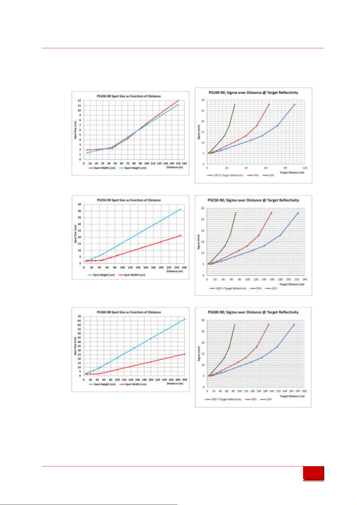
9.3 Laser Spot size and Sigma Diagrams
Triple-IN
GmbH
PS100-90
low res. Internet brochure
low res. Internet brochure
PS250-90
PS300-90
© Triple-In GmbH • 11/01/2017 14:31:00
PSxxx-90 Laser Scanner User's Manual
58

Triple-IN
0,5
mrad
0,09
°
GmbH
9.4 Laser Spot pattern
PS300-90 PS250-90 PS100-90
low res. Internet brochure
low res. Internet brochure
0,029°
0,029°
0,029°
0,5 mrad
0,115°
Normal Scan
Mode
0,09°
0,076°
Normal Scan Mode
0,09°
0,5 mrad
0,031°
Normal Scan Mode
© Triple-In GmbH • 11/01/2017 14:31:00
PSxxx-90 Laser Scanner User's Manual
59

Triple-IN
GmbH
PS300-90 PS250-90 PS100-90
Fast Scan Mode
low res. Internet brochure
low res. Internet brochure
Fast Scan Mode
Fast Scan Mode
© Triple-In GmbH • 11/01/2017 14:31:00
PSxxx-90 Laser Scanner User's Manual
60
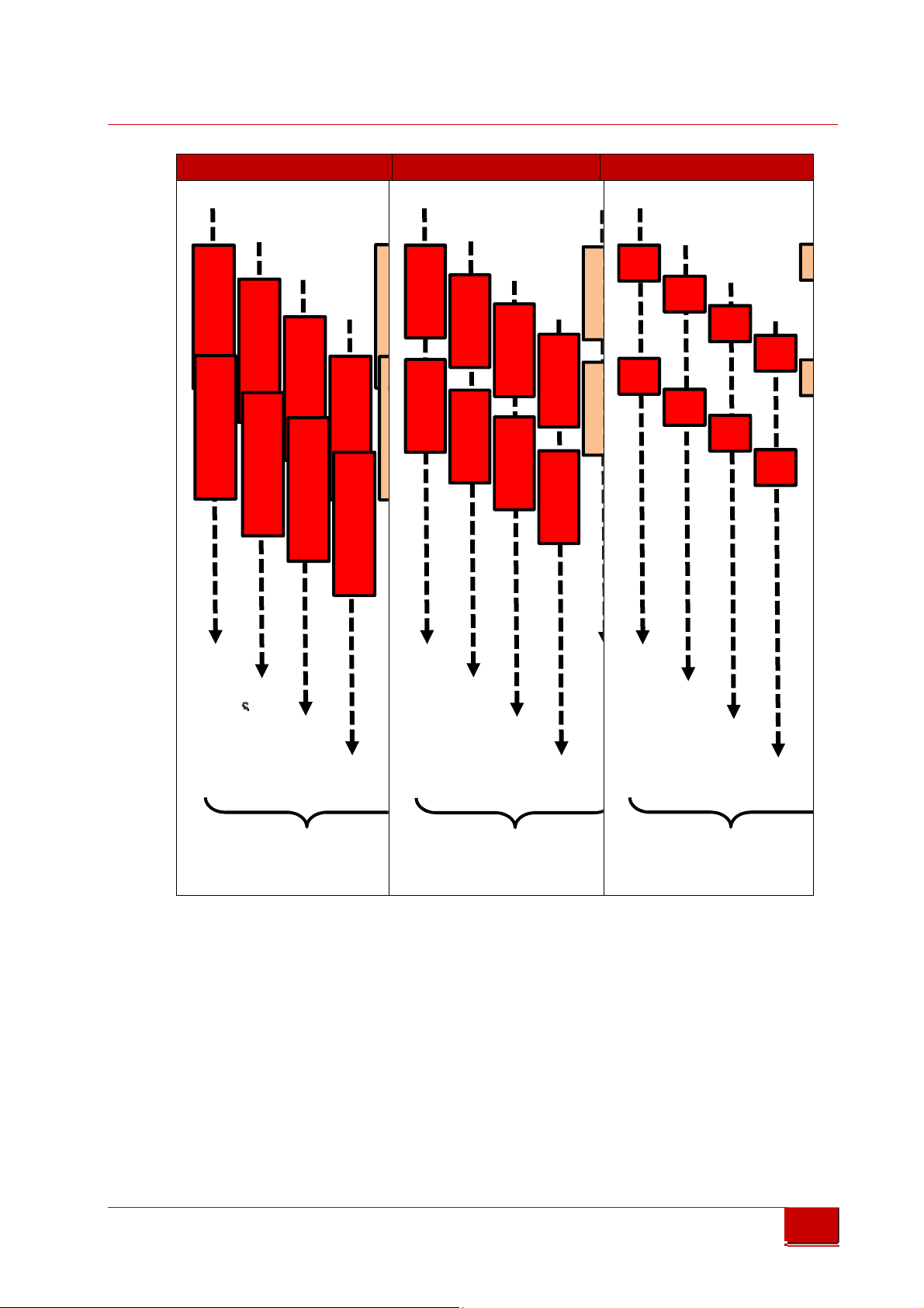
Triple-IN
one on top of the other
one on top of the other
GmbH
PS300-90 PS250-90 PS100-90
low res. Internet brochure
low res. Internet brochure
Scan
1
one on top of the
other
9.5 3D CAD Model
A 3D CAD model (STEP format) of the PS Laser Scanner outlines is available on
demand.
© Triple-In GmbH • 11/01/2017 14:31:00
PSxxx-90 Laser Scanner User's Manual
61

Triple-IN
GmbH
9.6 PSxxx-90 Laser Scanner Outlines
low res. Internet brochure
low res. Internet brochure
Picture 28 PSxxx-90 Laser scanner outlines (no scale)
© Triple-In GmbH • 11/01/2017 14:31:00
PSxxx-90 Laser Scanner User's Manual
62

Triple-IN
GmbH
9.7 Serial Multifunction cable layout
low res. Internet brochure
low res. Internet brochure
Picture 29 Serial multifunction cable
© Triple-In GmbH • 11/01/2017 14:31:00
PSxxx-90 Laser Scanner User's Manual
63

Triple-IN
GmbH
9.8 Ethernet and PoE cable layout
low res. Internet brochure
low res. Internet brochure
Picture 30Data and PoE cable
© Triple-In GmbH • 11/01/2017 14:31:00
PSxxx-90 Laser Scanner User's Manual
64

10 Index
10.1 Table of Figures
Triple-IN
GmbH
Picture 1 Triple-IN webserver login ............................................................................ 4
low res. Internet brochure
low res. Internet brochure
Picture 2: PS Laser Scanner front view ....................................................................... 6
Picture 3: PS Laser Scanner rear side. ......................................................................... 6
Picture 4 Principle of operation .................................................................................. 8
Picture 5: Scan area and Sensor origin ....................................................................... 9
Picture 6 Storage packaging ...................................................................................... 11
Picture 7: Mounting thread holes ............................................................................. 12
Picture 8: Connector rubber gaskets ........................................................................ 13
Picture 9: Using the quick locking connectors .......................................................... 13
Picture 10: M12 Data and PoE scheme (plug side view) ......................................... 14
Picture 11 Scheme of the cross-linked power connectors....................................... 15
Picture 12: M12 Serial interface connector scheme (plug side view) ..................... 16
Picture 13 Measurement Board (MPU) DSUB9 male DTE pin layout (socket view) 18
Picture 14 Communication Board DSUB9 male DTE pin layout (socket view) ........ 18
Picture 15 Digital output wiring scheme .................................................................. 19
Picture 16 Incremental encoder wiring scheme ....................................................... 20
Picture 17 Network configuration for PS Laser Sensors with TCP/IP Manager ....... 22
Picture 18 Restore the Network configuration with TCP/IP Manager ..................... 23
Picture 19: TeraTerm with Measurement Board startup message ......................... 25
Picture 20: TeraTerm with Communication board startup message ....................... 25
Picture 21 PSControlProgram network connection dialog ...................................... 30
Picture 22 PSControlProgram Parameter view ......................................................... 31
Picture 23 Near-field configuration, example with zone 3 ...................................... 41
Picture 24 Multi-Echo with Master Echo selection .................................................. 42
Picture 25 Digital switching output example signal pattern .................................... 46
Picture 26 Teraterm Firmware file selection ............................................................ 49
Picture 27 Teraterm XMODEM upload ..................................................................... 49
Picture 28 PSxxx-90 Laser scanner outlines (no scale) ............................................. 62
Picture 29 Serial multifunction cable ........................................................................ 63
Picture 30Data and PoE cable ................................................................................... 64
© Triple-In GmbH • 11/01/2017 14:31:00
PSxxx-90 Laser Scanner User's Manual
65

Triple-IN
GmbH
10.2 Document versions
Date Changes
2016-10-06 Chapter “Document updates and firmware updates”
Correct accuracy in tech. data
low res. Internet brochure
low res. Internet brochure
2016-10-13 Remove PS150-90 type. Not in production any more.
Change closes distance of PS100-90 to 0.6 m.
2017-01-10 Update technical data according to production year 2017
Updated outline drawings
© Triple-In GmbH • 11/01/2017 14:31:00
PSxxx-90 Laser Scanner User's Manual
66
 Loading...