

Page 1
COMMANDER AND
EMBASSY SERIES
OWNER'S MANUAL
Experience the Difference
Page 2

Triple E
Recreational Vehicles
301 Roblin Blvd., Box 1230
Winkler, Manitoba
Canada R6W 4C4
Tel: (204) 325-4361
Fax: (204) 325-5241
Email:WWW.tripleerv.com
Production improvement is a continuing process at Triple E
Recreational Vehicles. Thus, we reserve the right to change
specications, operating instructions, standards and options
on any and all products without prior notice. Errors and omissions excepted. The diagrams included were current at the
time of printing.
NOTE
PART NUMBER:
146-4587-JAN05
Page 3

P.O. Box 1230
Winkler, Manitoba
Canada R6W 4C4
Tel: (204) 325-4361
Fax (204) 325-5241
www.tripleerv.com
Printed in Canada
Page 4
FORWARD
A WORD TO MOTORHOME OWNERS
Welcome to the growing number of discerning people
who own and operate a Triple E Motorhome.
Our company takes great pride in the quality and excellence that the Triple E name represents. We have sought
to anticipate your needs and desires with respect to
safety, convenience, styling, and engineering.
WARNING
Failure to read the manual completely and thoroughly may lessen your total enjoyable experience.
We appreciate having you as our customer and have
provided this manual and various component manuals to introduce you to the many features of your new
motorhome. Each person using the motorhome should
take time to read this manual before operation. It will
help you to better understand the many built-in operational features of this recreation vehicle. Talk to your
dealer if you have any questions about your unit.
We hope you will enjoy your new motorhome, and we
wish you pleasant and carefree driving.
Modications that are not approved by Triple
E may void the warranty and transfer responsibility for the changes to the owner.
This manual is intended to be a guideline. This
manual despite our best eorts should not be
considered comprehensive in all details. We
invite you to use this manual to help you learn
the basics about your vehicle. The component
operation instructions i.e. fridge, stove, etc. are
incluced in the owner's information package.
INFORMATION AND SAFETY
The driver may need a special License to drive this
Recreational Vehicle or tow a trailer behind it. Check
with the local transportation authorities to nd out
the road and driving regulations in the area you
intend to travel.
Throughout the manual, certain instructions, procedures and information is emphasized with the
words IMPORTANT, CAUTION and WARNING. These
key words denote the level of care that each operator should exercise on mechanical and safety items.
IMPORTANT
This vehicle is equipped with the latest systems, appli-
ances and operational equipment making it consider-
ably more complicated than a normal automobile.
The use of three way systems; 120V, 12V and propane
needs careful consideration as the availability of energy
in both the 12V and propane systems has a limited capacity and volume. Due caution should be applied and
in case of doubt, clarication from the authorized Triple
E dealer or our factory service department should be
obtained. Do not modify the unit in any way. Unauthorized modication may impair the function or life of the
vehicle and could lead to an accident.
Page 5

TABLE OF CONTENTS
SECTION DESCRIPTION PAGE SECTION DESCRIPTION PAGE
1 Introduction ...................................................................1-1
1.1 Operator's Manuals ....................................1-1
1.2 Information Package ..................................1-1
1.3 Options and Equipment ...........................1-1
1.4 Keys ..................................................................1-1
1.5 Vehicle Certication Label .......................1-2
1.6 Identication Information ........................1-4
1.7 Exterior Feature Identication ................1-5
1.8 Service Assistance .......................................1-7
1.9 Reporting Safety Defects ..........................1-7
1.10 Driving Comfort ...........................................1-7
2 Safety ................................................................................2-1
2.1 General Safety ..............................................2-1
2.2 Driving Safety ...............................................2-2
2.3 Fuel (Motor and LP Gas) ............................2-2
2.4 Asphyxiation .................................................2-3
2.5 Formaldehyde ..............................................2-3
2.6 LP Gas Leaks ..................................................2-3
2.7 Alarms..............................................................2-4
2.8 Electrical .........................................................2-4
2.9 Loose Components ....................................2-5
2.10 Maintenance .................................................2-5
2.11 Emergency Exits ..........................................2-5
3 Preparation .....................................................................3-1
3.1 Vehicle Preparation ....................................3-1
3.1.1 Keys ..................................................................3-1
3.1.2 Vehicle Loading............................................3-1
3.1.3 Trailer Towing ................................................3-2
3.1.4 Auxiliary Vehicle Towing ...........................3-2
3.1.5 Parking, Levelling and Blocking .............3-3
4 Controls 4-1
4.1 Chassis Controls ...........................................4-1
4.2 Dash Controls ...............................................4-1
4.3 Driver's Door (Commander Only) ..........4-3
4.4 Driver's/Co-Pilot Seat .................................4-4
4.5 Cocktail Seat ..................................................4-5
4.6 Seat/Shoulder Belts ....................................4-5
4.7 DVD/VCR Combination .............................4-7
4.8 TV ......................................................................4-8
4.9 Entrance Door ...............................................4-9
4.10 Refrigerator ................................................ 4-10
4.11 Light Switches ........................................... 4-11
4.12 Comfort Control Center .........................4-12
4.13 Furnace ........................................................ 4-13
4.14 Thermostatically
Controlled Celing Fan ............................. 4-14
4.15 Water/Plumbing System ........................ 4-15
4.15.1 Water Heater .............................................. 4-15
4.15.2 Water Heater Bypass ...............................4-16
4.15.3 Water Pump ................................................ 4-17
4.15.4 Utility Compartment ............................... 4-18
4.15.5 Water System (Embassy Only) ............. 4-20
4.16 TV Antenna ................................................. 4-21
4.17 Satelite Dish (Optional) ...........................4.22
4.18 Battery Disconnect .................................. 4-23
4.19 Slide-Out Room (Optional) ................... 4-24
4.20 System Monitor ......................................... 4-25
4.21 Energy Management System
(EMS) (Optional) ........................................ 4-26
5 Driving ...........................................................................5-1
5.1 Pre-Trip Inspection ......................................5-1
5.2 Emergency Equipment Check List ........5-2
5.3 Before Departing .........................................5-2
5.4 Engine Operation ........................................5-2
5.5 Driving Characteristics ..............................5-3
5.6 Driving Safety Tip ........................................5-3
5.7 Travel Tips .......................................................5-4
5.8 Quick Loading Check List .........................5-5
5.9 Severe Weather Information ...................5-6
6 Safety Equipment Operation ....................................6-1
6.1 Fire Prevention .............................................6-1
6.1.1 Fire Safety Tips ..............................................6-1
6.1.2 Fire Extinguisher ..........................................6-2
6.2 Emergency Escape ......................................6-3
6.3 Alarms..............................................................6-4
6.3.1 LP Gas Alarm .................................................6-4
6.3.2 Carbon Monoxide Alarm ..........................6-5
6.3.3 Smoke Alarm .................................................6-6
6.4 Rear View Camera/Monitor System ......6-8
7 Traveling ..........................................................................7-1
7.1 Preparation ....................................................7-1
7.2 Baggage Loading ........................................7-1
7.3 Vehicle Weight-Loaded .............................7-1
7.4 Front Axle Tire Alignment ........................7-1
7.5 Maximum Occupancy................................7-1
7.6 Seat Belts ........................................................7-2
7.6.1 Lap Belts .........................................................7-2
Page 6

TABLE OF CONTENTS
SECTION DESCRIPTION PAGE SECTION DESCRIPTION PAGE
7.6.2 Shoulder/Lap Belts .....................................7-2
7.6.3 Care and Cleaning .......................................7-3
7.6.4 Child Restraints ............................................7-3
7.7 Mirrors .............................................................7-3
7.8 Free Standing Table & Chairs ...................7-4
7.9 Refuelling .......................................................7-4
8 Emergencies While Driving .......................................8-1
8.1 Hazard Warning Lights ..............................8-1
8.2 Flat Tire ............................................................8-1
8.3 Towing .............................................................8-2
8.4 Overheating ..................................................8-2
8.5 Jump Starting ...............................................8-3
9 Home Use ........................................................................9-1
9.1 Parking ............................................................9-1
9.2 Motorhome Levelling System
(Optional) .......................................................9-1
9.3 Slide Out Room ........................................... 9-3
9.3.1 Slide Out Room Operation .......................9-3
9.3.2 Slide Out Room
Emergency Operation ...............................9-5
9.4 Slide Out Room Troubleshooting ..........9-6
9.5 Central Vacuum System ............................9-6
9.6 Prolonged Occupancy ...............................9-6
10 Electrical Systems ...................................................... 10-1
10.1 120-Volt AC System .................................10-1
10.1.1 External Power Cord (Shoreline) ......... 10-1
10.1.2 Power Control Center
(Optional - Commander Only) ............. 10-2
10.1.3 120-Volt Circuit Breakers........................ 10-2
10.1.4 Ground Fault Circuit Interrupter
(GFCI) ............................................................10-3
10.2 Auxiliary 120-Volt Generator ................ 10-4
10.2.1 Generator Safety ....................................... 10-4
10.2.2 Generator Operation ............................... 10-5
10.2.3 Automatic Power Transfer Switch.......10-6
10.2.4 Generator Refuelling ............................... 10-6
10.3 12-Volt DC System .................................... 10-7
10.3.1 Automotive Batteries .............................. 10-7
10.3.2 Auxiliary Batteries .................................... 10-7
10.3.3 12-Volt Coach Fuses ................................ 10-8
10.3.4 Battery Maintenance ............................... 10-8
10.3.5 Battery Condition Meter ......................10-10
10.4 Trailer Wiring Connector ......................10-10
10.5 Electrical Schematics ............................10-11
10.6 Electrical Circuit Panels ........................10-12
11 LP Gas System .......................................................... 11-1
11.1 Safe Use of LP Gas ....................................11-1
11.2 How LP Gas Works .................................... 11-1
11.3 Selecting Fuel Types ................................ 11-2
11.4 LP Tank System .......................................... 11-2
11.5 LP Tank Capacity ....................................... 11-2
11.6 Relling LP Tank ........................................ 11-3
11.7 Air in the LP Tank ...................................... 11-4
11.8 Travelling LP Gas ....................................... 11-4
11.9 Regulator ..................................................... 11-4
11.10 LP Gas Leaks ............................................... 11-5
11.11 LP Gas Detector ........................................11-5
12 Water/Plumbing System .........................................12-1
12.1 Fresh Water System ................................. 12-1
12.1.1 Fresh Water Tank Filling
Procedure .................................................... 12-2
12.1.2 Water Pump ................................................ 12-2
12.1.3 Water Pump Switch ................................. 12-3
12.1.4 Water Pump Filter ..................................... 12-4
12.1.5 Water System Access ............................... 12-4
12.1.6 Water Pump Initial Start-Up.................. 12-4
12.1.7 Water Pump Troubleshooting.............. 12-5
12.1.8 Disinfection of Water Tank .................... 12-5
12.1.9 External Water Supply ............................ 12-6
12.2 Waste Systems ........................................... 12-6
12.2.1 Grey Water - Waste Holding Tank........12-6
12.2.2 Black Water - Waste Holding
Tank ............................................................... 12-6
12.2.3 Dumping Holding Tanks ........................ 12-7
12.2.4 Tank Rinse ................................................... 12-8
12.2.5 Do's And Don'ts Holding Tanks ........... 12-8
12.2.6 Using On-Site Sewer Hook-Ups ........... 12-8
12.2.7 Holding Tank Level Indicators .............. 12-9
12.3 Plumbing System Operation ................ 12-9
12.3.1 Water Heater ............................................12-19
12.3.2 Toilet ...........................................................12-10
12.3.3 Shower .......................................................12-10
12.3.4 Exterior Shower (Optional) .................12-11
12.3.5 Water Purier
(Optional - Commander only) ............12-11
12.4 Plumbing Specications ......................12-11
12.4.2 Plumbing Schematics ...........................12-12
13 Appliances And Interior Features ........................ 13-1
13.1 Refrigerator ................................................ 13-1
13.1.1 Operating Instructions ...........................13-1
13.1.2 Operating Tips ........................................... 13-1
Page 7

TABLE OF CONTENTS
SECTION DESCRIPTION PAGE SECTION DESCRIPTION PAGE
13.1.3 Exterior Fridge Access ............................. 13-2
13.2 Range And Oven.......................................13-2
13.2.1 Lighting Burners ....................................... 13-2
13.2.2 Lighting Oven Pilot ................................... 13-3
13.2.3 Operating Oven Control ........................ 13-3
13.2.4 Shut Down Instructions ..........................13.3
13.2.5 Range Hood ............................................... 13-3
13.2.6 Safety Tips ................................................... 13-3
13.3 Microwave Oven ....................................... 13-4
13.4 Monitor Panel ............................................ 13-4
13.5 LP Gas Furnace ..........................................13-5
13.6 Roof Air Conditioners.............................. 13-6
13.7 TV Antenna ................................................. 13-6
13.8 TV Signal Amplier ...................................13.7
13.9 Television ..................................................... 13-7
13.10 Video Cassette Recorder ........................ 13-8
13.11 Video Control Center .............................. 13-8
13.12 Phone And Cable TV Hook-Ups ........... 13-8
13.13 AC/DC Inverter .......................................... 13-8
13.14 Sleeping Facilities ..................................... 13-9
13.15 Seats ............................................................13-10
13.16 Seat / Shoulder Belts .............................13-10
13.17 Fresh Water Toilet ...................................13-11
13.18 Electric Step (Optional) ........................13-12
13.19 Screen Windows .....................................13-12
13.20 Power Roof Vent .....................................13-12
13-21 Central Vacuum System .......................13-13
13.22 Washer/Dryer Hook-Ups ......................13-13
14 Care And Maintenance ............................................ 14-1
14.1 Exterior ......................................................... 14-1
14.2 Interior .......................................................... 14-2
15 Motorhome Maintenance ......................................15-1
15.1 Chassis Customer Service ...................... 15-1
15.2 Engine Access ............................................ 15-1
15.3 Engine Cooling System ..........................15-1
15.4 AC And Oil Coolers ................................... 15-1
15.5 Tires ...............................................................15-1
16 Storing Your RV ........................................................... 16-1
17 Winterization ............................................................... 17-1
17.1 Cold Temperature Operation ............... 17-1
17.1.1 Chassis .......................................................... 17-1
17.1.2 LP Gas ........................................................... 17-1
17.1.3 Furnace ........................................................ 17-1
17.1.4 Waste System ............................................. 17-1
17.1.5 Fresh Water System ................................. 17-1
17.1.6 Exterior shower .......................................... 17-1
17.2 Cold Temperature Storage .................... 17-2
17.2.1 Water System Winterization .................17-2
17.2.2 Water Purier(Commander only) ........ 17-2
17.2.3 Fridge Ice Maker ....................................... 17-2
17.2.4 Washer/Dryer (Comander only) .......... 17-3
17.2.5 De-Winterize Water System .................. 17-3
Page 8

COMMANDER / EMBASSY
1 INTRODUCTION
ment. It utilizes the latest design features and manufacturing techniques to insure safe, ecient and troubleCongratulations on your choice of a Triple E built Motorhome for your travelling and touring comfort and enjoy-
free operation at all times.
1.1 OPERATOR'S MANUALS
All owners/operators should read, understand and
follow all instructions in this the motorhome manual,
chassis manual and manuals for all auxiliary systems
and appliances. A few minutes spent reading the appropriate manual will pay rich dividends in providing
safe, ecient and trouble-free operation.
Refer to the Ford or Workhorse Custom Chassis Operator's Manual for detailed information on the chassis.
Refer to the appropriate manual supplied for auxiliary
equipment and appliances as required.
This manual covers the systems, controls and operation unique to this vehicle. Always keep the information package with the vehicle for easy reference. Pass
the package on to new operators or owners as appropriate for their information as well. Use the Table of
Contents or Index to nd specic information.
If more information is required or you do not understand something, please contact:
Your Triple E RV dealer
or
Triple E Recreational Vehicles
301 Roblin Blvd., Box 1230
Winkler, Manitoba Canada
R6W 4C4
Tel: (204) 325-4361
Fax: (204) 325-5241
E-mail: [email protected]
1.2 INFORMATION PACKAGE
An information package is provided with each vehicle
and includes information on specic systems, features
and appliances including:
1. Chassis
2. Air Conditioning
3. Generator
4. Furnace / Thermostat
5. General Operation
6. Entertainment System
7. Leveling System
8. Water Heater
9. Safety
10. Flooring and Counter Tops
11. Rear View Monitor
12. Electric Step
13. Fridge
14. Alarm System
15. Plumbing Fixtures
16. Roof and Side Walls
17. Appliances
18. Converter
19. EMS (Energy Management System)
20 Inverter
21. Central Vac
22. Satellite Dish
1.3 OPTIONS AND EQUIPMENT
The Triple E Recreational Vehicles are available in
various sizes, models and oor plans. The equipment,
accessories and components described in this manual
may not necessarily apply to your vehicle. Refer to the
material provided in the information package for the
detailed instructions unique to your unit.
1.4 KEYS
It is a good idea to keep a record of all key code numbers
and keep them in a safe place - not in your vehicle. Use
the charts in this manual but make a duplicate copy to
be stored elsewhere.
1-1
Page 9
COMMANDER / EMBASSY
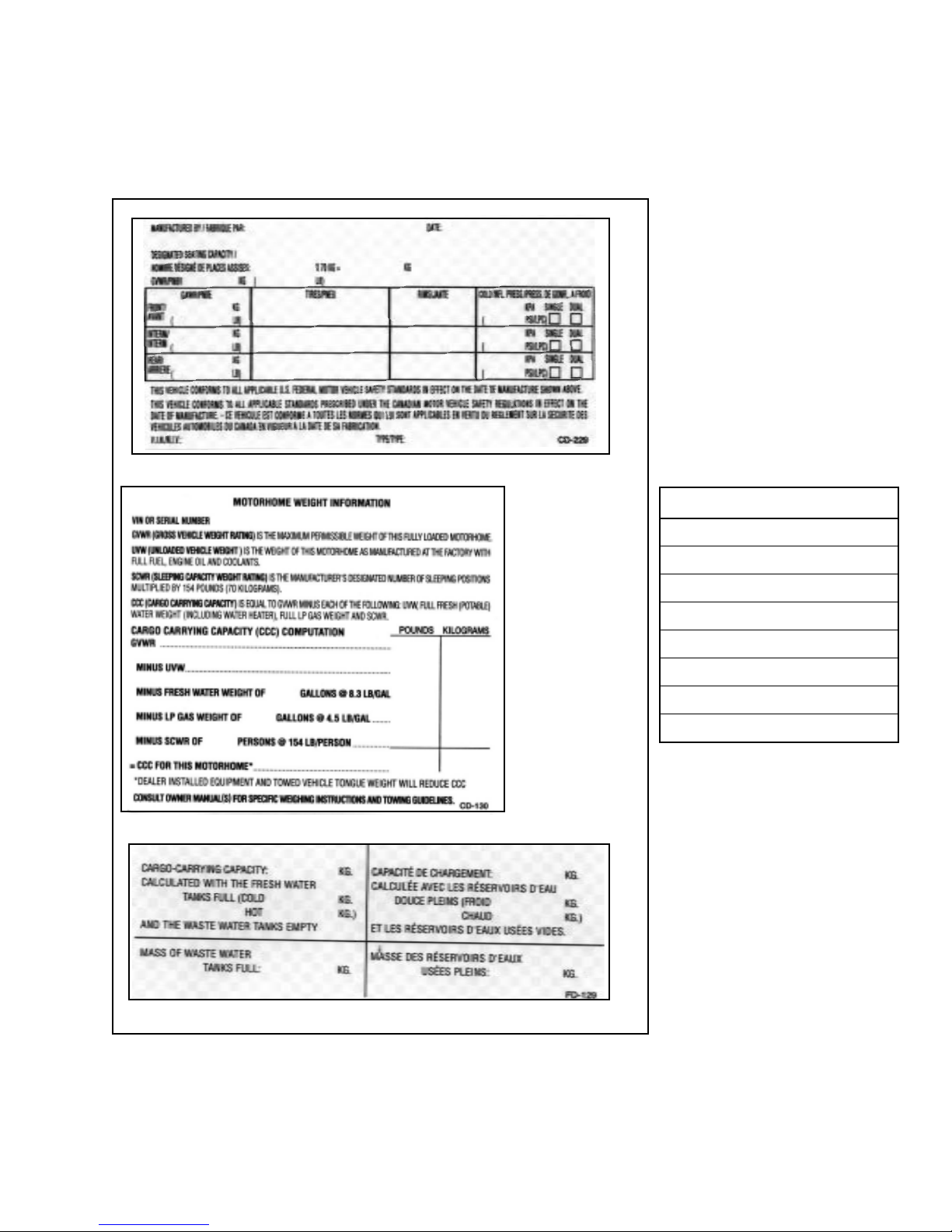
1.5 VEHICLE CERTIFICATION LABEL
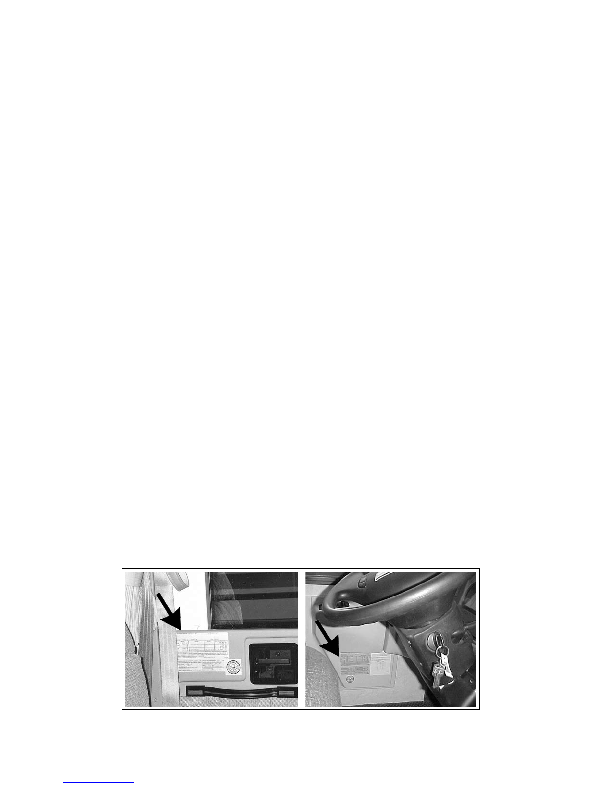
This label contains vehicle identication and other important reference information. The vehicle certication
label is located on the sidewall to the left of the steering wheel, or on the driver's door. Never remove or destroy
this label.
Custom Paint Colors
U.S.
2003 Blue Horizon Decor
Skirt 1991 Ford Mocha Frost
RM #21146 Mfg. #DD
Fig. 1-2 Color Code Sample
Fig. 1-1 CERTIFICATION LABELS
Canadian
1-2
Page 10
COMMANDER / EMBASSY
Denitions:
1. Recreational Vehicle manufacturer.
2. R.V. manufacture date.
3. Month and year of manufacture at Triple E Recreational vehicle.
4. Gross Vehicle Weight Rating (GVWR):
Is the maximum permissible weight of this fully
loaded motorhome.
5. Unloaded Vehicle Weight (UVW):
Is the weight of this motorhome as manufac-
tured at the factory with full fuel, engine oil and
coolants.
6. Cargo Carrying Capacity (CCC):
Is equal to GVWR minus each of the following:
UVW, full fresh (potable) water weight (including
water heater), full LP - Gas weight and SCWR.
7. Gross Combination Weight Rating (GCWR):
Means the maximun allowable loaded weight
of this motorhome and towed trailer or towed
vehicle.
8. Sleeping Capacity Weight Rating (SCWR):
Is the manufacturer's designated number of
sleeping positions multiplied by 154 lbs (70 Kgs)
9. Gross Axle Weight Rating (GAWR):
Is the value specied as the load carring capacity
of a single axle system, as measured at the tireground interfaces.
10. Tires :
Tires recommended to meet handling and safety
requirements
and safety requirements.
12. Cold Tire Ination Pressure:
Ination pressures recommended (while cold) for
the tires originally equipped on your vehicle.
13. Rear Axle Wheel Conguration:
Single axle/Dual wheels.
14. Serial Number:
This is the serial number assigned to the com-
pleted vehicle by Triple E Industries.
15. Vehicle Identication Number (VIN):
This number identies the chassis on which the
motorhome is built.
16. Type:
States the National Highway Trac Safety Associ-
ation (NHTSA) designated usage classication for
your motorhome. MPV signies a Multi-purpose
Passenger Vehicle.
17. Model:
Lists the Triple E product model number of your
vehicle.
18. Color:
Signies the color code number of the decor
used throughout the vehicle. This number is
necessary for ordering replacement cushions,
curtains, carpet, etc. It is located in the wardrobe
beneath the specication sheet.
NOTE
Triple E motorhomes are built according
to CSA and RVIA standards.
11. Rims:
Wheel rims recommended to meet handling
Fig. 1-3 IDENTIFICATION INFORMATION (LABEL LOCATION)
1-3
Page 11

COMMANDER / EMBASSY
1.6
Take a few minutes to ll in this information. It will be a handy reference for you. The Chassis label is located on
the sidewall to the left of the steering wheel or on the driver's side door. (The component model and serial numbers are recorded on a serial number data sheet stored in the owner information package.)
Your Name __________________________________
Motorhome Model ___________________________
Coach Serial No. ______________________________
Chassis Serial No. _____________________________
Date Purchase _______________________________
Dealer Name ________________________________
Address ____________________________________
____________________________________________
Phone No. ___________________________________
Insurance Policy
Agent Name _____________________________
Policy No. _______________________________
Agent's Phone No. ________________________
Range/Oven
Manufacturer ____________________________
Model __________________________________
Serial No. ________________________________
Microwave Oven
Manufacturer ____________________________
Model __________________________________
Serial No. ________________________________
Video Cassette Player
Manufacturer ____________________________
Model __________________________________
Serial No. ________________________________
Television
Manufacturer ____________________________
Model __________________________________
Serial No. ________________________________
Dash Stereo
Manufacturer ____________________________
Model __________________________________
Serial No. ________________________________
IDENTIFICATION INFORMATION
Water Heater
Manufacturer ____________________________
Model __________________________________
Serial No. ________________________________
Furnace
Manufacturer ____________________________
Model __________________________________
Serial No. ________________________________
Air Conditioner #1
Manufacturer ____________________________
Model __________________________________
Serial No. ________________________________
Air Conditioner #2
Manufacturer ____________________________
Model __________________________________
Serial No. ________________________________
Generator
Manufacturer ____________________________
Model __________________________________
Serial No. ________________________________
Miscellaneous
Key No. _________________________________
Paint Codes
________________________________________
________________________________________
________________________________________
1-4
Page 12
COMMANDER / EMBASSY
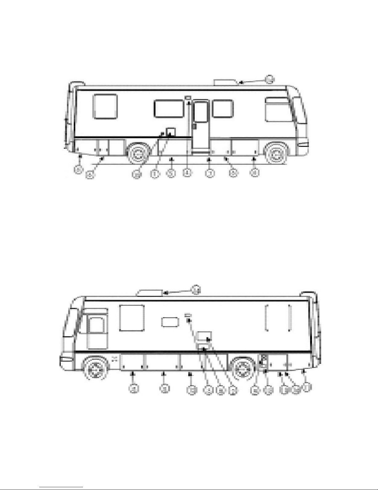
1.7 EXTERIOR FEATURE IDENTIFICATION - TYPICAL MODEL
Composite model shown for illustration purposes only. Actual locations of features depends on coach model
and options.
*
Fig. 1-3 EXTERIOR IDENTIFICATION - COMMANDER ONLY (RIGHT)
1. Water Heater Service Access.
2. Refrigerator Service Access.
3. Range Hood Vent.
4. Porch Light.
5. Propane Tank
6. Storage Compartment
7. Entrance Step.
8. Furnace Service Access Panel.
9. Engine and Generator Fuel Tank Fill.
10. Battery Compartment.
11. Generator Compartment.
*
*
12. Utility Service Compartment.
Includes: Water Drain Valves.
Fresh Water Filler.
Winterization Valve.
Holding Tank Drain Valves.
Black Water Flush System.
13. Sewer Hose Storage.
14. Roof Air Conditioner.
15. Exterior 120v Receptacle.
16. Shore Power Hook-Up.
Fig. 1-4 EXTERIOR IDENTIFICATION - COMMANDER ONLY (LEFT)
NOTE
Some equipment shown may be
optional.
1-5
*
CAUTION: Be careful. These features
*
may become hot while water heater or
furnace are in use.
Page 13
COMMANDER / EMBASSY
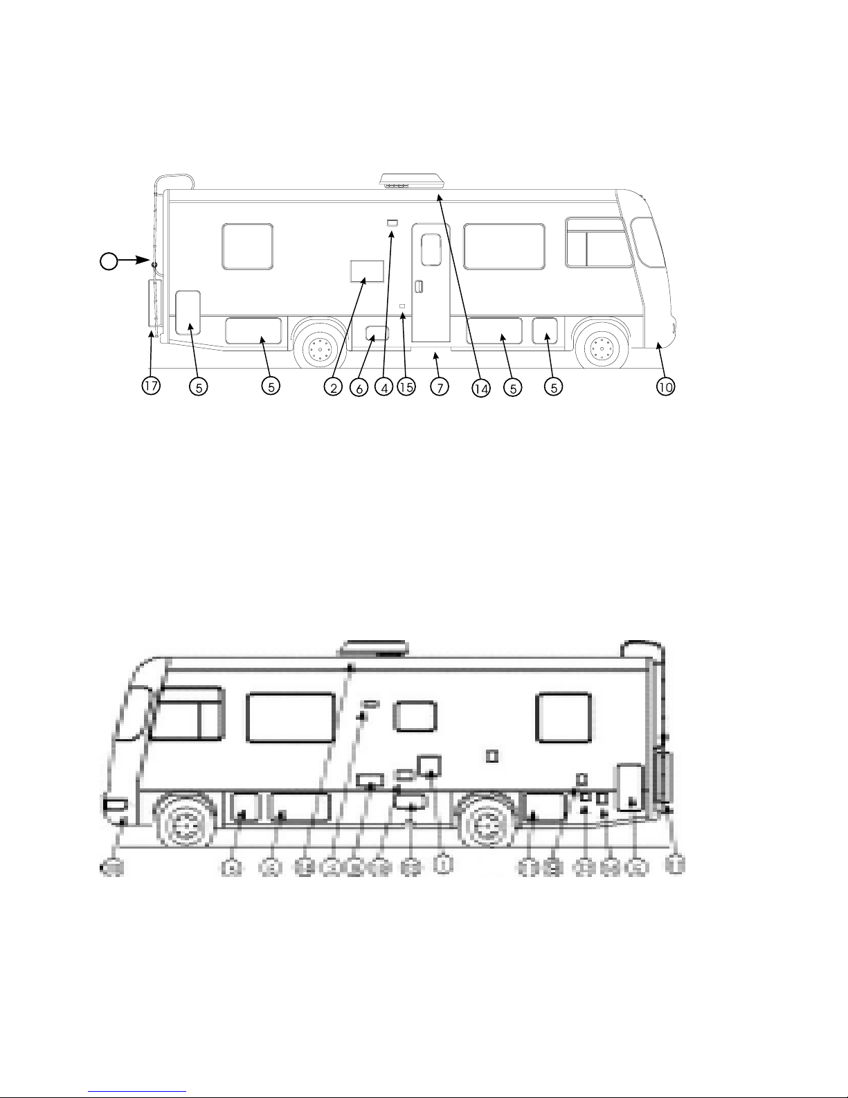
TYPICAL MODEL
Composite model shown for illustration purposes only. Actual locations of features depends on coach model
and options.
18
Fig. 1-5 EXTERIOR IDENTIFICATION - EMBASSY ONLY (RIGHT)
1. Water Heater Service Access.
2. Refrigerator Service Access.
3. Range Hood Vent.
4. Porch Light.
5. Storage Compartment.
6. Propane Tank Access
7. Entrance Step.
8. Furnace Service Access Panel.
9. Engine and Generator Fuel Tank Fill.
10. Battery Compartment.
11. Generator Compartment.
*
12. Utility Service Compartment.
Includes: Water Drain Valves.
13. Sewer Hose Storage.
14. Roof Air Conditioner.
15. Exterior 120v Receptacle.
16. Shore Power Hook-Up
17. Spare Tire
*
18. Ladder (Opt.)
19. Exterior Shower (Opt.)
Fig. 1-6 EXTERIOR IDENTIFICATION - EMBASSY ONLY (LEFT)
NOTE
Some equipment shown may be optional.
*
*
CAUTION: Be careful. These features
*
may become hot while water heater or
furnace are in use.
1-6
Page 14

COMMANDER / EMBASSY
1.8 SERVICE ASSISTANCE
Your RV dealer is best equipped to provide any additional information you need and to answer any
questions you may have about the operation of
your motorhome. When it comes time for service,
remember that your dealer knows your vehicle best
and is interested in your satisfaction. Your dealer will
provide quality maintenance and assistance during
the period of your ownership. It is advisable that you
follow a regular maintenance schedule to keep your
vehicle functioning at its best.
Should you require warranty assistance while travelling, take your motorhome to the nearest Triple E
dealer for help.
1.9 REPORTING SAFETY
DEFECTS
If you believe that your motorhome has a safety
defect of any kind that could cause injury, or death,
contact Triple E immediately. As well, make sure to
contact the National Highway Trac Safety Administration (NHTSA) if you are a resident of the US, or
Transport Canada if you are a Canadian resident and
report your concern.
The NHTSA or Transport Canada will investigate the
concern should there be a number of similar complaints. They have the authority to order a recall and
repair campaign depending on the nature and severity of the problem.
The NHTSA may be reached by using the Auto Safety
Hotline at 1-800-424-9393 (366-0123 in the Washington, DC area) or by writing to: NHTSA, US Department
of Transportation, Washington, DC 20590. The Hotline
will also provide you with additional information on
motor vehicle safety.
In Canada, call 1-613-993-9851 or write to: Transport
Canada and Road Safety, 2780 Sheeld Road, Ottawa,
Ontario K1B 3V9.
1.10 DRIVING COMFORT
Triple E has made every eort to design and construct
your motorhome for your comfort and safety. We
know that your investment is important to you as well
as to us. Our design team has dedicated itself to the
development of the best motorhome comfort and
protection packages in the industry. Here are some
of the features that make your unit one of the nest
motorhomes on the road today.
1. Passenger Comfort
a. Optional, ducted roof-mounted air condition-
ing units with up to 13,500 BTU's of cooling
capacity per unit. Available with the air conditioner is a heat strip to supplement the forced
air furnace. An optional single 15,000 BTU unit
is also available.
b. High output chassis air conditioner for travel-
ling comfort.
c. Electronic ignition LP gas furnace designed to
maintain a comfortable temperature of +20
degrees C (+70 degrees F) when the temperature outside is -20 degrees C (-5 degrees F).
However, temperatures may vary in the coach
depending on register location.
d. High output chassis heater for your driving
comfort.
e. Thermally ecient vacuum-bonded composite
walls, oor and roof, using rigid foam insulation
for strength are designed to reduce freezethrough.
f. One piece headliner for warmth and noise
reduction.
g. Automatic, electronic ignition water heater.
h. Motor-aid water heater to keep the water in the
water heater hot while travelling.
2. Unit Protection
a. Fiberglass (Commander) or FRP (Embassy) all-
weather exterior nish. Easy to maintain. Will
not rust or pit.
b. Seamless EPDM rubber roof (Embassy only) to
ensure a weather proof seal.
c. Seamless FRP one piece roof sheeting (Com-
mander only) to ensure a weather proof seal.
d. Tubular aluminum reinforced walls and roof.
Steel reinforced oor.
e. Urethane undercoating for protection against
dust and moisture and to provide extra insula-
tion against heat and cold.
f. Fully insulated, heated holding tank compart-
ment and discharge valves to prevent winter
freeze-up (Optional on Embassy). Enclosed to
protect against road damage.
g. Simplied manual water winterization system
complete with water heater bypass.
h. Ultraviolet stabilized exterior components to
resist fading and deterioration.
i. Exterior screws and fasteners that resist corro-
sion.
j. Heavy duty mud aps for additional protection
against ying stones and other debris.
1-7
Page 15

COMMANDER / EMBASSY
2 SAFETY
Safety, comfort and ease of operation are key considerations during the design and manufacturing of all
Triple E Motorhomes. It is the responsibility of the
owner or operator to read, understand and follow all
instructions in the Motorhome, chassis and appliance
or auxiliary system manuals and safety signs on the
vehicle. Specic items, procedures or instructions are
identied with the key words IMPORTANT, CAUTION
and WARNING to emphasize areas of special concern.
These key words are dened as:
IMPORTANT -
CAUTION -
WARNING -
The safety glyph identies an area that involves
the personal safety of the operator, passengers or a
bystander. Always read, understand and follow the
instructions and information in the safety sign or
manual instruction. Do not take chances with safety.
Most accidents can be prevented.
In this section we have compiled a series of items relating to safety that everyone should follow. Although
this compilation is thorough, we realize that it does
not cover everything. Each person has the responsibility of following all listed safety items covered in this
and other manuals.
This word is used to highlight
or emphasize a specic procedure, information or result for
a system or the vehicle.
This word is used to highlight
or emphasize a specic procedure or information that if not
followed will result in damage
to a system or the vehicle.
This word is used to high-
light or emphasize a specic
procedure or information that
if not followed can involve
your personal safety as well as
cause vehicle damage.
2.1 GENERAL SAFETY
1. The most important safety feature on this vehicle
is the operator. It is the operator's responsibility
to read, understand and follow all safety and operating instructions in the vehicle, chassis, appliance and system manuals. Most accidents can be
prevented.
2. A person who has not read and understood all
operating and safety instructions is not qualied
to operate this vehicle. Untrained or uninformed
operators expose themselves, passengers and
other drivers/vehicles/property to possible serious injury or death and property damage.
3. Do not modify the vehicle in any way. Unauthorized modication may impair the function and/or
safety and could aect the life of the vehicle.
4. All approved driver and passenger seats are
equipped with seat belts. Swivel seats when occupied while driving, each must be locked in the
forward facing direction. The driver and each passenger must occupy only the approved seats and
fasten seat belts when the unit is moving. Do not
allow any passengers in the vehicle unless they
have their seat belt attached while in an approved
seat. When the vehicle is moving, no one should
be using the bedroom, galley, or bathroom area of
the unit .
5. Always fasten the seat belt low on the torso and
keep it snug to transmit the force from the belt
into the hip/pelvic area of the body. Pregnant
women should wear a lap/shoulder belt whenever
possible. Wear the belt snug and low throughout
the pregnancy.
6. Review the location, function and operation of the
escape window with everyone who will be riding
in or using the motorhome. Inspect the locking
mechanism.
7. Establish a monthly re extinguisher inspection
program to keep the extinguisher in good condition and fully charged. Inspect the extinguisher
again prior to a vacation or trip.
8. Always exercise extreme care and caution when
climbing onto and walking on the roof.
2-1
Page 16

COMMANDER / EMBASSY
2.2 DRIVING SAFETY
1. Only trained and licensed drivers are allowed to
drive this vehicle.
2. Observe all applicable road and driving regulations. Check with local transport authorities if you
have any questions.
3. Inspect the vehicle before driving. Adjust, repair
or replace components or systems to maintain
vehicle in good driving condition. Do not drive
the motorhome unless it is in good condition.
4. Do not make adjustments such as seat position,
tilt steering wheel etc. while driving.
5. A motorhome is considerably larger and heavier than an automobile and results in dierent
handling characteristics. Allow more space for
stopping, turning, passing, parking, accelerating
etc. during operation. The extra height results in
dierent stability characteristics. Drive at a slower
speed when turning, cornering or on rough terrain. Use extra care in adverse conditions such as
rain, darkness, snow, sleet, icy surface, hilly terrain,
rough road or a soft surface. Refer to your chassis
manual for additional instructions.
6. Maintain brakes in top condition at all times. Allow extra distance for stopping. Be extra vigilant
in adverse surface conditions such as wet, icy,
slushy, rough or a soft surface when applying the
brakes. After going through water, slush or snow,
apply the brakes carefully in an open area to
check if one side grabs. Use gentle pedal pressure
to dry the brakes and restore uniform operation.
Do not operate vehicle if uneven brake action
persists.
2.3 FUEL
1. Do not smoke when lling vehicle/generator fuel
tank, or LP gas tank.
2. Extinguish all pilot lights before refuelling.
3. Do not ll the LP gas tank or vehicle fuel tank
when the generator is running.
4. Do not bring or store fuel or LP gas containers,
gasoline or other ammable liquids in the vehicle.
Vapours can be released causing breathing difculties or an explosion or re. LP gas containers
vent excess pressure into the atmosphere.
5. Do not ll LP gas containers more than 80% of
capacity. Overlling can lead to excessive venting
or gas ow and result in an explosion or re.
6. Do not use an open ame to check for an LP gas
leak. Use soapy water and watch for bubbles.
Close valve on tank and latch all covers, caps and
doors after lling system.
7. Do not connect natural gas supply to the LP system.
8. Install LP gas regulators with the pressure regulator vent facing downward. Do not obstruct vent
hole. In cold weather, condensation can get into
the regulator and cause freeze-up. Use a light
bulb to thaw out. Do not use an open ame or
heat lamp to thaw out.
9. Turn igniter knob to create a spark at the burner
when burner is turned on. Large volumes of gas
can lead to an explosion and re if igniter is not
turned when the burner is turned on. Turn burner
o and let gas dissipate before trying to relight if
it does not light immediately.
(MOTOR AND LP GAS)
10. Do not use the furnace when the vehicle is moving. Turn the gas o at the LP container.
11. Do not obstruct LP gas compartment when parking. Open access allows emergency workers to
close master valve if an emergency occurs.
2-2
Page 17

COMMANDER / EMBASSY
2.4 ASPHYXIATION
1. Do not use portable fuel-burning equipment including wood and charcoal grills and stoves in the
vehicle. The use of this equipment can generate
deadly carbon monoxide gas or cause res.
2. Provide proper ventilation when using the gas
range or oven to prevent asphyxiation. Do not
use the oven or range to heat the vehicle. Long
term use of these appliances for space heating increases the chance of asphyxiation. Before using
the range or oven:
a. Open overhead vent or turn on exhaust fan,
and…
b. Open window.
3. Avoid breathing the exhaust fumes from a gas
engine and LP gas burner such as the vehicle or
generator engines and the range, oven, refrigerator, furnace or water heater. Position the vehicle
so the wind blows the engine exhaust fumes
away. Provide ventilation to the inside of the vehicle for adequate air exchange when appliances or
furnaces are being used to prevent a build-up of
carbon monoxide. Be sure all alarms are working.
4. Do not run vehicle or auxiliary generator engine
in a conned area such as a garage unless you are
just moving it out of the area.
5. Use vent or air conditioning fan to force fresh air
into the interior when vehicle is in an open area
with the engine running for more than just a short
time.
6. Maintain engine(s) exhaust system components
in top condition to prevent fumes from entering
vehicle. Check when changing oil, when exhaust
sound changes or when underbody is damaged.
7. Close rear windows when driving to prevent
drawing exhaust fumes into vehicle.
2.5 FORMALDEHYDE
Formaldehyde based adhesives are used in some components in this vehicle and may release small amounts
of formaldehyde fumes into the vehicle for an unknown period of time until fully dissipated. Some
people who are allergic to the fumes may experience
irritation to the eyes, ears, nose and throat. Small
infants may have a more serious reaction. Although
long range eects are not well understood, testing
to date has not revealed any serious health eects in
humans at the level of emission from these products.
Reduce the eects of the formaldehyde fumes by
keeping the unit well ventilated.
2.6 LP GAS LEAKS
1. Check your RV unit for gas leaks annually before
you start using it for the season.
2. If you smell gas shut o the gas supply imediatly.
Do not operate electrical switches. Air out the unit
and have the gas system checked before using
again.
For U.S. units the following label has been placed
in the vehicle near the range area:
WARNING
IF YOU SMELL GAS
1. Extinguish any open ame, pilot lights and all smoking material.
2. Do not touch electrical switches.
3. Shut o thegas supply at the container valve(s) or gas supply connection.
4. Open doors and other ventilating openings.
5. Leave the area until the odour clears.
6. Have the gas system checked and leakage source corrected before
using again.
3. Use soapy water to check for leaks and watch for
bubbles. Do not use an open ame.
4. Correct or repair leak(s) before using appliances or
vehicle again.
2-3
Page 18

2.7 ALARMS
COMMANDER / EMBASSY
1. LP Gas Alarm:
a. Sounds whenever there is an unsafe amount of
propane gas in the vehicle.
b. Follow instructions on safety sign and air out
vehicle to silence alarm.
c. Have a qualied service personnel nd the
leak and correct the problem before using unit
again.
2. Carbon Monoxide Alarm:
a. Sounds whenever there is an unsafe amount of
carbon monoxide gas in the vehicle.
b. Open doors, vents and windows to air out ve-
hicle and silence alarm.
c. Have a qualied service personnel check all
burners, clean, repair or replace any defective
burners.
d. Remove all fuel or wood burning devices from
inside vehicle.
e. Have a qualied serviceman check all engine
exhaust system components. Repair or replace
any defective components. Position motorhome so wind blows exhaust fumes away.
3. Smoke Alarm:
a. Sounds whenever there is an unsafe amount of
smoke in the vehicle. Always use exhaust fan
over the stove when cooking.
b. Open doors, vents and windows to air out ve-
hicle and silence alarm. Correct and eliminate
smoke source.
c. Check alarm on a regular basis. Check when
removing from storage, before trips and weekly
thereafter. Depress center button to test alarm
electronics. Test alarm sensor by blowing
smoke (from safe, re-free source) past sensor.
If alarm does not sound when testing, determine source of problem and correct or replace
alarm.
d. Do not remove battery to silence alarm. When
alarm “beeps” every minute, battery is weak
and must be replaced. Do not allow battery to
go dead. Be sure to replace with recommended
battery. Test after battery is replaced.
e. Clean and vacuum opening on smoke alarm
once a month.
f. Do not try to repair alarm. Replace it.
g. Smoke alarms are not perfect and do not re-
spond in all situations. The best safeguard is
re prevention.
4. Recurring alarm(s) indicate the slow accumulation
of LP gas, carbon monoxide, or smoke. Have an
authorized service center check system and identify
source. Correct problem before resuming use of
unit.
5. Refer to alarm manual(s) for more detailed instruc-
tions.
2.8 ELECTRICAL
1. Use care when working around batteries. The gases
given o when charging are explosive. Keep sparks
and ames away from battery. Wear protective
clothing, eye protection and remove jewellery. Do
not short across terminals.
2. Do not overload electrical circuits. Replace circuit
breakers and fuses with components of similar
capacity. Do not replace with larger capacity components (breakers or fuses).
3. Be sure motorhome is well grounded to prevent
shocks or electrocution. Do not plug utility power
cord into an outlet that is not grounded. Do not
modify any plug to t a receptacle for which it was
not designed. Do not attach an extension cord to
the utility power cord.
4. Use care when handling electrical appliances,
power cords and other components. Misuse or
abuse of electrical components can lead to shocks
or electrocution. Do not use electrical components,
cords or appliances with bare feet, wet hands or
while standing in water or on wet ground.
2-4
Page 19
COMMANDER / EMBASSY
2.9 LOOSE COMPONENTS
Any loose component can become a projectile
during sudden stops, manoeuvring or an accident
therefore:
1. Tie, strap or secure all tables, chairs and other
furniture before travelling.
2. Close, latch or lock all doors, drawers, panels and
gates before travelling.
3. Turn all swivel seats in the forward facing direction and lock before moving. All passengers must
be seated in a seat that is equipped with a seat
belt and the seat belt fastened.
4. Stow all cooking, serving, eating and other loose
components before moving.
2.10 MAINTENANCE
1. Do not attempt to start vehicle by hot wiring or
shorting across starter terminals.
2.11 EMERGENCY EXITS
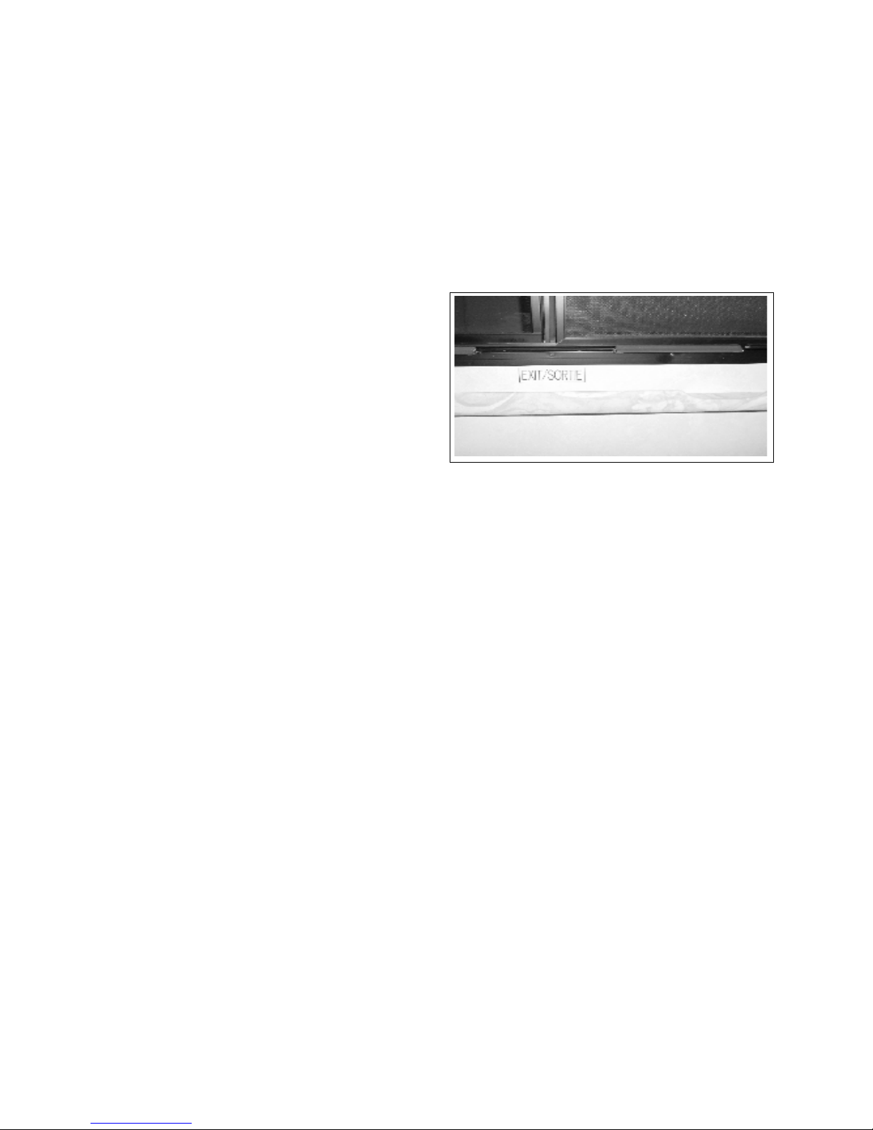
Each Motorhome is designed with an emergency exit
window in the sleeping area and the side windows can
also be used as an alternate emergency exit.
1. Emergency Exit:
Press down on the red latches of the emergency
egress window and push out the window. (The
egress window has hinges on top).
Fig. 2-1 EMERGENCY EXIT
2. Do not remove radiator cap when radiator or
engine is hot. Steam or hot uid can be released.
Check coolant level in overow reservoir.
3. Do not go under a vehicle that is only supported
with a jack.
4. Do not mix bias and radial ply tires on the vehicle.
Mixing dierent types of tires can aect handling
characteristics. Replace with the same size, type
and load rating.
2-5
Page 20

COMMANDER / EMBASSY
3 PREPARATION
Refer to information pack supplied with the
Motorhome prior to using or driving the unit. Read,
understand and follow instructions in the chassis,
motorhome, appliance and system manuals.
Also follow the safety tips provided in Section 2.
Motorhomes can be used many ways and in many
conditions or circumstances. We have tried to
compile operational and safety instructions to cover
the normal conditions encountered with the unit.
However these instructions are not all-inclusive. Each
user or operator has the responsibility to use common
sense around the unit and to consult a dealer if you
have any questions
3.1 VEHICLE PREPARATION
3.1.1 KEYS
Several number coded keys are supplied with the
vehicle and include ignition, side door, baggage
compartment, generator compartment and others
depending upon the features of your unit. Always
keep a list of these numbers in a safe place (not in the
vehicle) for easy reference should you misplace any of
the key(s). Supplying a locksmith with these numbers
will allow them to cut a key to t your lock.
3.1.2 VEHICLE LOADING
The components of your vehicle are designed to
provide satisfactory service if the vehicle is not loaded
in excess of either the gross vehicle weight rating
(GVWR) or the maximum front and rear gross axle
weight ratings (GAWR's). These ratings are listed on
the Canadian and U.S. Department of Transport Sticker
located on the driver door panel.
the value specied by the Chassis manufacturer as the
maximum allowable loaded weight of this motorhome
with its towed trailer or towed vehicle combined.
To check that your motorhome is properly loaded,
drive the fully loaded vehicle to a scale and weigh as
follows:
a. Drive only the front wheels onto the scale to
obtain the front gross axle weight.
b. Next, place the entire vehicle (both axles) onto
the scale to obtain the gross vehicle weight.
c. Drive forward till only the rear wheels are
on the scale and obtain the rear gross axle
weight.
Compare the gross vehicle weight (b) with the GVWR
on the sticker. If the gross vehicle weight exceeds the
GVWR, you will have to reduce the total vehicle load. If
the gross vehicle weight (b) is less than the GVWR on
the sticker, check the front and rear gross axle weights
against the front and rear GAWR's on the sticker. If either
axle weight exceeds the GAWR for that axle, redistribute
the load to ensure that loads on front and rear axles are
within the required limit.
Heavier items should be loaded as centrally and as low
as possible. Lighter items may be stored in cabinets,
closets and drawers. Luggage or similar cargo inside
your RV should be secured to prevent it from causing
damage.
Take no te of thi s label in all exterior storage
compartments
The (GVWR) Gross Vehicle Weight Rating, is the maximum
permissible weight of this fully loaded motorhome.
The (UVW) Unloaded Vehicle Weight means the weight
of the motorhome as manufactured at the factory with
full fuel, engine oil and coolants. The UVW does not
include cargo, fresh water, LP Gas, Occupants, or factory
and dealer installed options.
The (SCWR) Sleeping Capacity Weight Rating is the
manufacturer's designated number of sleeping
positions multiplied by 154 pounds (70 kilograms).The
(CCC) Cargo Carrying Capacity is equal to GVWR minus
each of the following: UVW, full fresh (potable) water
weight (including water heater), full LP-Gas weight and
SCWR.
The (GCWR) Gross Combination Weight Rating, means
CAUTION
Do not overload Baggage Compartments
Total Vehicle Load Not to Exceed The Maximum
GVWR/GAWR/GCWR Of The Chassis.
3-1
Page 21
COMMANDER / EMBASSY
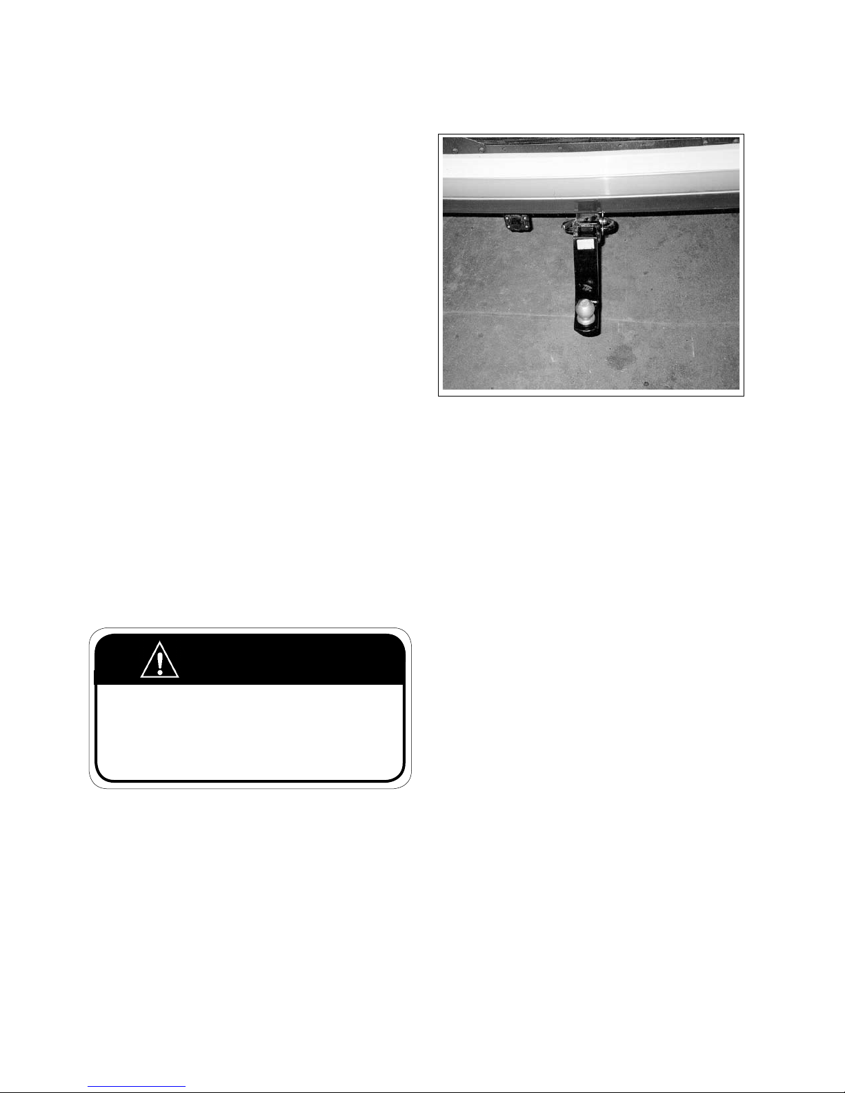
3.1.3 TRAILER / VEHICLE TOWING
A trailer can aect the handling, durability, performance and economy of your motorhome. The factory
installed towing hitch is rated for:
a. 500 lb. - maximum hitch or
tongue weight.
b. 5000 lb. - maximum trailer weight.
The combined weight of the motorhome and the towed
vehicle should not exceed the Gross Combined Weight
Rating (GCWR). Also, the combined weight of the motorhome and the tongue weight of the towed vehicle
should not exceed the motorhome's Gross Vehicle
Weight Rating (GVWR) or its rear Gross Axle Weight Rating (GAWR) as listed on the Vehicle Certication label.
To be sure of the correct balance in weight, it is advised
that you take your loaded vehicle to a weigh-scale to
determine the actual weight distribution. After you
have done this once, you will have a better idea on how
to load in the future.
Remember, your motorhome will handle dierently
with a trailer in tow. Stopping distances will change.
Make sure your trailer is equipped and connected to
your motorhome with the proper brake system.
When descending a steep or long grade, reduce speed
and shift to a lower gear to control vehicle speed. Avoid
prolonged or frequent application of brakes if at all possible to prevent overheating and possible failure of the
braking system.
Fig. 3-1 TRAILER HITCH
CAUTION
Exceeding any of the recommended gross
vehicle weight ratings may result in vehicle
damage.
Do not install a weight equalizing type of
hitch on your motorhome.
WARNING
For safety towing and vehicle handling, maintain proper
vehicle and trailer weight distribution.
The total weight of the motorhome and the vehicle
towed must not exceed the GCWR rating as stated on
the Vehicle Certication label.
3-2
Page 22
COMMANDER / EMBASSY
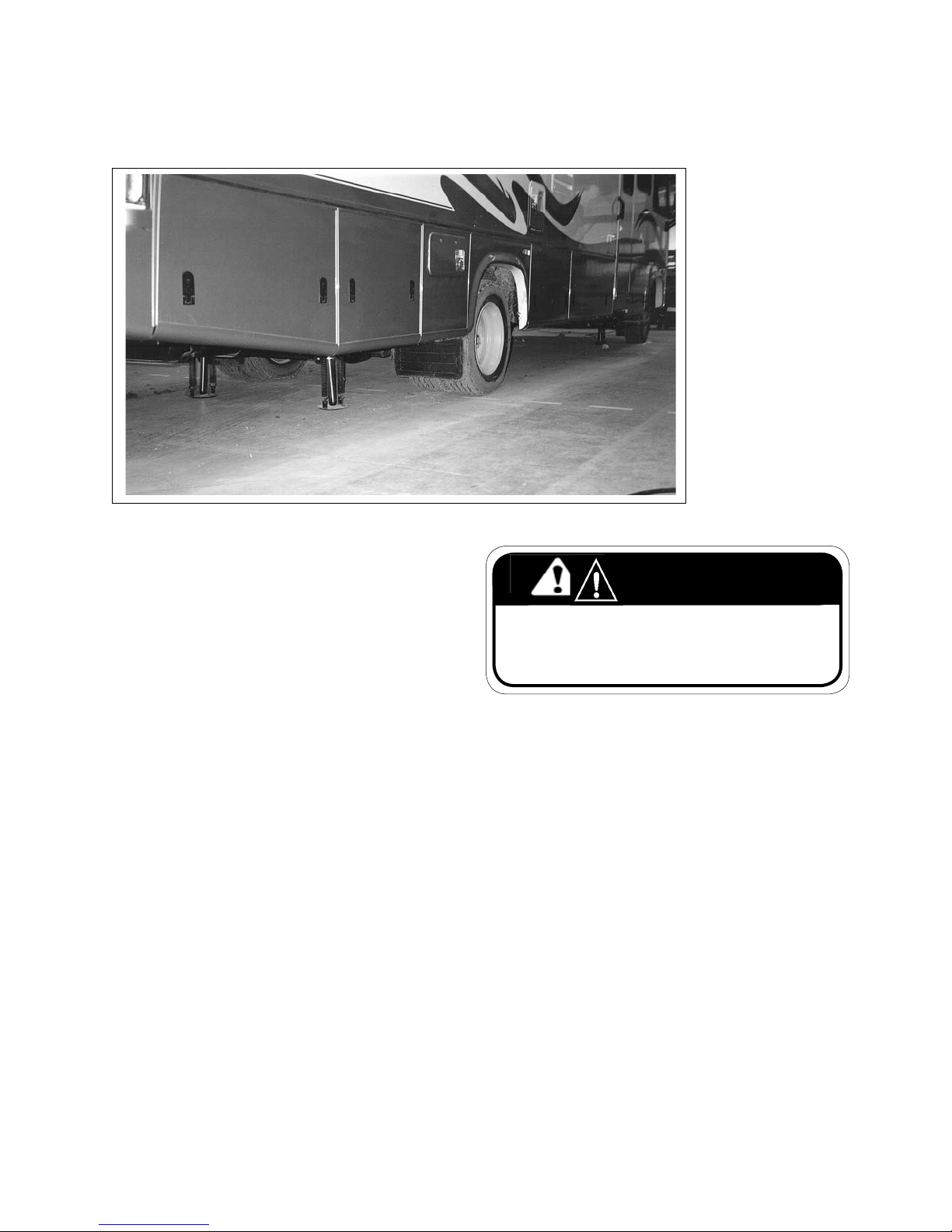
3.1.5 PARKING, LEVELING AND BLOCKING
Fig. 3-2 PARKING
Try to pick a spot as level as possible on which to park
your motorhome. You may choose to drive in or back
in depending on your personal preference. Remember,
however, that all your utility connections (water, sewer,
electrical, etc.) are all located on the left side of your
motorhome.
It is important that you make sure your motorhome is
levelled correctly whenever you park, not only for your
own comfort but for the proper functioning of your
appliances such as your refrigerator. The vapor cooling
system can “lock up” and damage the refrigerator if it is
not level. As well, the various water and waste levels in
the dierent holding tanks will have a reduced holding
capacity if not level. In addition, the sewer drainage
system needs to be level in order to function properly.
If your motorhome is equipped with the Hydraulic Levelling System, follow the directions under Motorhome
Leveling in Section 9.2 of this manual to level your
motorhome. If not equipped, use leveling blocks to
raise the lower end or side of the motorhome to bring
it to level. After your motorhome is levelled, use wheel
chocks or similar devices in front or behind the wheels
in order to prevent your motorhome from rolling o
the blocks. When placing blocks beneath a set of dual
wheels make sure you block both tires so that the load
is not carried by one tire.
WARNING
Always exercise care and caution when parking and level-
ling your motorhome. Make sure everyone, especially
children, are well clear until the vehicle has been stabilized
and parked with the ignition o.
3-3
Page 23
COMMANDER / EMBASSY
4 CONTROLS
It is the responsibility of each owner, operator, driver
or user to be familiar with the positions, functions and
settings of all controls. Each new person should be
trained in all aspects of motorhome operation prior
to starting. Review this section as often as required
to understand the controls. See the Chassis Operators
manual for further details. Contact your dealer if you
have any other questions.
4.1 CHASSIS CONTROLS
Refer to the manual provided in the information
package from the chassis manufacturers for details
on the standard automotive, steering column,
transmission and instrument cluster controls, lights
and gauges.
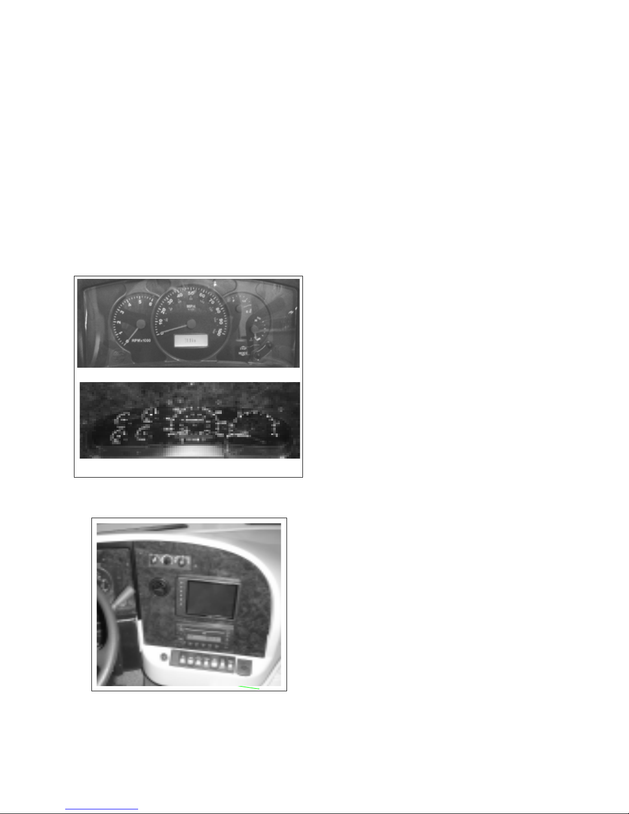
Workhorse Custom Chassis
Ford
Fig. 4-1 INSTRUMENT Cluster
4.2 DASH CONTROLS
a
b
c
d
e
f
g
h
k
m
n
o
Fig. 4-2 RIGHT SIDE - UPPER
1. Right Side:
a. Climate Control:
This is the standard climate control used for
all Class A Triple E vehicles and includes both
the heating and cooling functions for the
driving section of the vehicle.
b. AM/FM CD Deck:
This is a standard AM/FM compact disc deck.
Refer to the deck manufacturers manual in
the information package for more details.
c. Cigarette lighter
d. Blank spot (room to add another switch)
e. Power sunvisor passenger side: (optional):
This push button switch controls the power
to the electric sun visor. Depress the bottom
portion of the switch to lower the sunvisor and
depress the top portion of the switch to raise
it up.
f. Radio switch:
This push button switch controls the power
to the stereo. Depress the bottom portion
of the switch to turn on the power from the
coach battery. Depress the switch again
to turn it o. Unit also has a switch in the
bedroom upper console and lower galley.
This switch allows the user to play the stereo
without turning on the ignition.
g. Auxiliary Generator Control (Optional):
This 3 position push button switch controls
the operation of the auxiliary generator.
Depress the bottom portion of the switch
against the spring to engage the starter to
the auxiliary generator. Release the switch
when the generator engine starts. Depress
the top portion of the switch and hold until
the generator turns o and then release.
h. Interior Courtesy Lights:
This push button switch controls the power
to the coach foot lights. Depress the lower
portion of the switch to turn the foot lights
on. Depress the top portion to turn them o.
k. Map Reading Lights (passenger side):
This push button switch controls the power
to the light above the passenger seat area.
Depress the bottom portion of the switch to
turn the map light on and the top to turn it
o.
m. Rear Auxiliary Heater Fan:
This push button controls the power to the
rear auxiliary heater. Depress the bottom
portion of the switch to turn the 2-speed fan
switch on and the top portion to turn it o.
n. Interior Lights:
This push button controls the power to the
interior lights above the dashboard.
o. 12-volt DC plug-in receptacle
4-1
Page 24
COMMANDER / EMBASSY
2. Left Side:
a
e
d
c
b
g
f
s
r
p
o
n
m
k
h
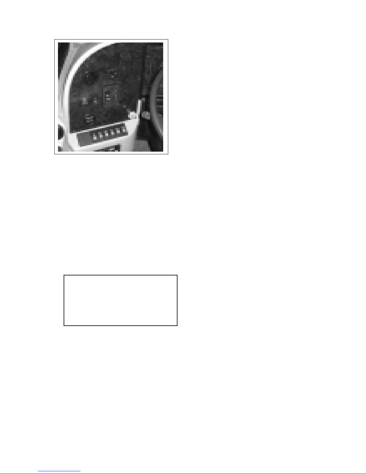
Fig. 4-3 LEFT SIDE - UPPER
a. Mirror Adjustment - Commander only:
This cluster of switches controls the position
of the rear view mirrors on both sides. Use
the center switch to select the left or right
mirror. Depress and hold the four outer
switches as required to move the mirror to
the desired position.
b. Jacks Down Light (Optional Included With Levelling
System):
This red light indicator alerts the
driver that the levelling jacks are in their
down position. It comes on when the ignition switch is switched on and the jacks are
down.
c. Antenna
d. Headlights:
IMPORTANT
The Daytime Running Lights (DRL) come
on at partial power whenever the engine
is running. The headlight switch must be
turned on for the headlights to operate at
full power.
Ford Chassis has a 3 position rotary switch
which controls the power to the vehicle head
lights. Turn fully counterclockwise to turn
o. Turn clockwise to the rst detent for the
parking and panel lights. Turn fully clockwise
to turn the headlights on at full power.
Workhorse Chassis has a rocker switch. De-
press the switch one notch to turn the park
lights on. Depress it all the way to turn the
headlights on.
e. Panel Lights:
This rotary switch controls the power to the
instrument panel lights. Roll the dial up
decrease the power and turn the lights o.
Roll down to increase power level and light
intensity.
f. Hourmeter (Optional):
This meter displays the generator operating
hours and accumulates time whenever the
generator is running.
g. Park Brake (Workhorse Chassis)
Pull the control knob to engage the parking
brake (See Chassis Operators Manual for
further detaisl).
h. Blank spot (room to add another switch)
k. Blank spot (room to add another switch)
m. Power sunvisor passenger side: (optional):
This push button switch controls the power
to the electric sun visor. Depress the bottom
portion of the switch to lower the sunvisor and
depress the top portion of the switch to raise
it up.
n. Driving Lights
Depress the bottom portion of this switch
to activate the fog lights (only come on with
the headlights in low beam). Depress the top
portion of the switch to turn them o.
o. Rear Docking lights:
This push button switch controls the power
to the rear docking lights. Depress the
bottom of the switch to turn the docking
lights on and the top portion of the switch to
turn it o.
p. Cockpit Overhead Fans (Optional):
This push button switch controls the power
to the fans mounted on the bottom of the
overhead cabinet. Depress the bottom
portion of the switch to turn the fan on and
the top portion of the switch to turn o.
The fans can be rotated to any position you
require.
r. Mirror Heaters - (Commander only):
This push button switch controls the power
to the exterior rear view mirror heaters.
Depress the bottom portion of the switch
to turn the heaters on and the top portion
to turn o. The heater will automatically be
shut o when the ignition switch is turned
o. The heater will also shut o once it
reaches its desired temperature.
s. Coach Battery Connect:
This spring loaded push button switch
controls the interconnect circuit between
the auxiliary and chassis batteries. Depress
and hold the switch to connect the auxiliary
batteries to the chassis batteries. Release the
switch to disconnect. Use this interconnect
only when the chassis batteries are too run
down to start the engine.
4-2
Page 25
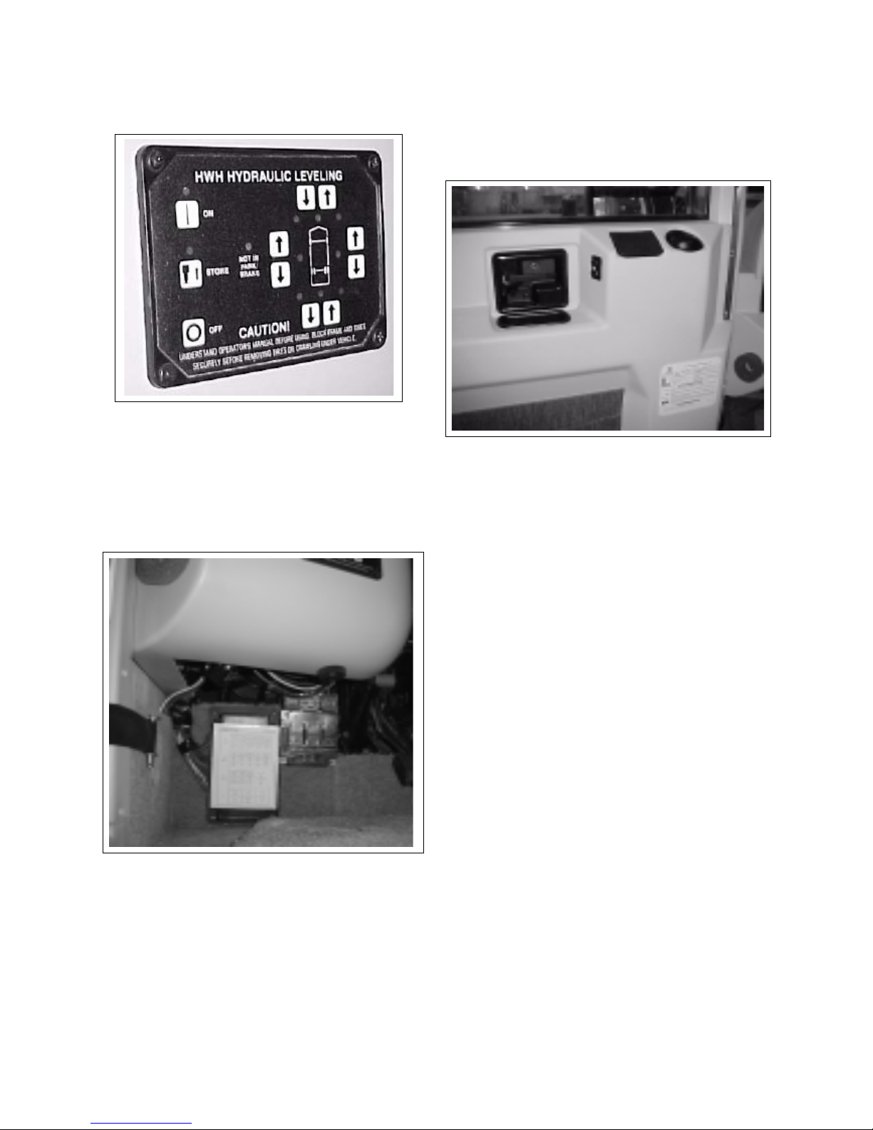
3. Left Side - Lower (Optional):
Fig. 4-4 LEFT SIDE LOWER
Computerized Levelling System:
This panel contains the controls for the com-
puterized hydraulic levelling system. Refer to
instructions in the information package for
more detailed instructions.
4. Left Side - Under Dash:
COMMANDER / EMBASSY
4.3 DRIVERS DOOR
Commander only
a
Fig. 4-6 DRIVERS DOOR
a. This rocker switch sets the position of the drivers
door window. Depress and hold the foward portion
of the switch to raise the window and back portion to
lower.
a
b
Fig. 4-5 UNDER DASH
a. Driveline Diagnostics Port:
This port is located under the left side of the
dash. Refer to chassis owner's manual in the
information package for more details.
b. Chassis fuse block. See Chassis Operator's
manual for further information.
4-3
Page 26
COMMANDER / EMBASSY
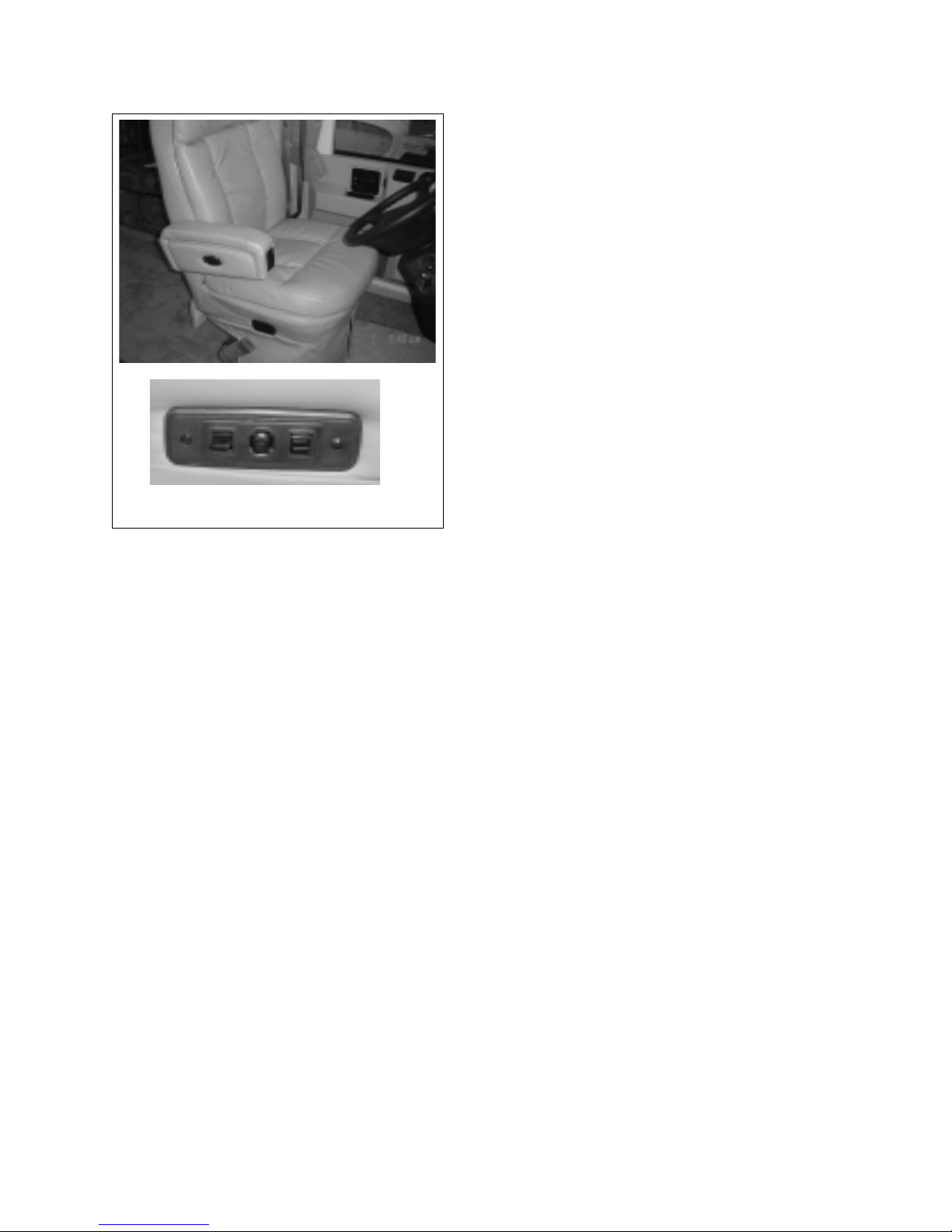
4.4 DRIVERS/CO-PILOT SEAT
4
3
2
1
Power Controls (Optional)
Fig. 4-7 CO-PILOT SEAT CONTROL (TYPICAL)
1. Forward-Back Position (Non-Powered Seat): Both
the drivers and co-pilot seats are designed with
a sliding base to allow the seat to be moved
forward or backward for occupant comfort.
A spring loaded latch is located at the right side
2. Swivel Lock:
Both the drivers and co-pilot seats are designed
A spring loaded latch is located at the right side
a
of the seat to release the sliding base. Pull on the
latch to release the lock, slide the seat as desired
and release the latch to lock it in position.
with a swivel base to allow the seat to be used for
driving or as part of the living room.
of the seat to release the swivel lock. Pull up on
the latch to release the lock. Swivel the seat as
desired. When the seat is turned facing forward
the swivel lock will automatically engage and
secure the seat. Do not move the vehicle unless
the drivers and co-pilots seats are locked in the
forward facing direction. On some oor plans the
seat may have to be moved to the most forward
position to rotate it.
1
3
The arm rests are designed for individual
adjustment. A spring loaded lever is located at the
tip of the arm rest. Pull the lever to release and
adjust the arm rest. Release the lever to lock it in
place.
4. Back Rest Angle:
This spring loaded lever located on the left
side of the seat controls the lock on the back rest
angle position mechanism. Pull the lever up and
hold to release the position lock. Gently lean
back to push the back rest down. Lean forward
to allow the back rest to tilt up. Release the lever
to engage the lock and hold the back rest in
position.
Power Seat Control (Optional on some models):
a. Front Of Seat Height:
This spring loaded to centre toggle switch sets
the height of the front of seat. Pull up and hold
the switch to raise the front of the seat. Push
down and hold to lower the front of the seat.
b. Forward-Back Up-Down Position:
This spring loaded to centre toggle switch sets
the longitudinal (forward-back) and the height
position of the seat. Push the switch forward
and hold to move the seat forward. Push the
switch rearward and hold to move the seat
back. Push the switch up and hold to move
the seat up. Push the switch down and hold to
move the seat down.
c. Back Of Seat Height:
This spring loaded to centre toggle switch sets
the height of the back of the seat. Pull up and
hold to raise the rear of the seat. Push down
and hold to lower the back of the seat.
3. Arm Rest Lock:
4-4
Page 27
COMMANDER / EMBASSY
4.5 COCKTAIL SEAT
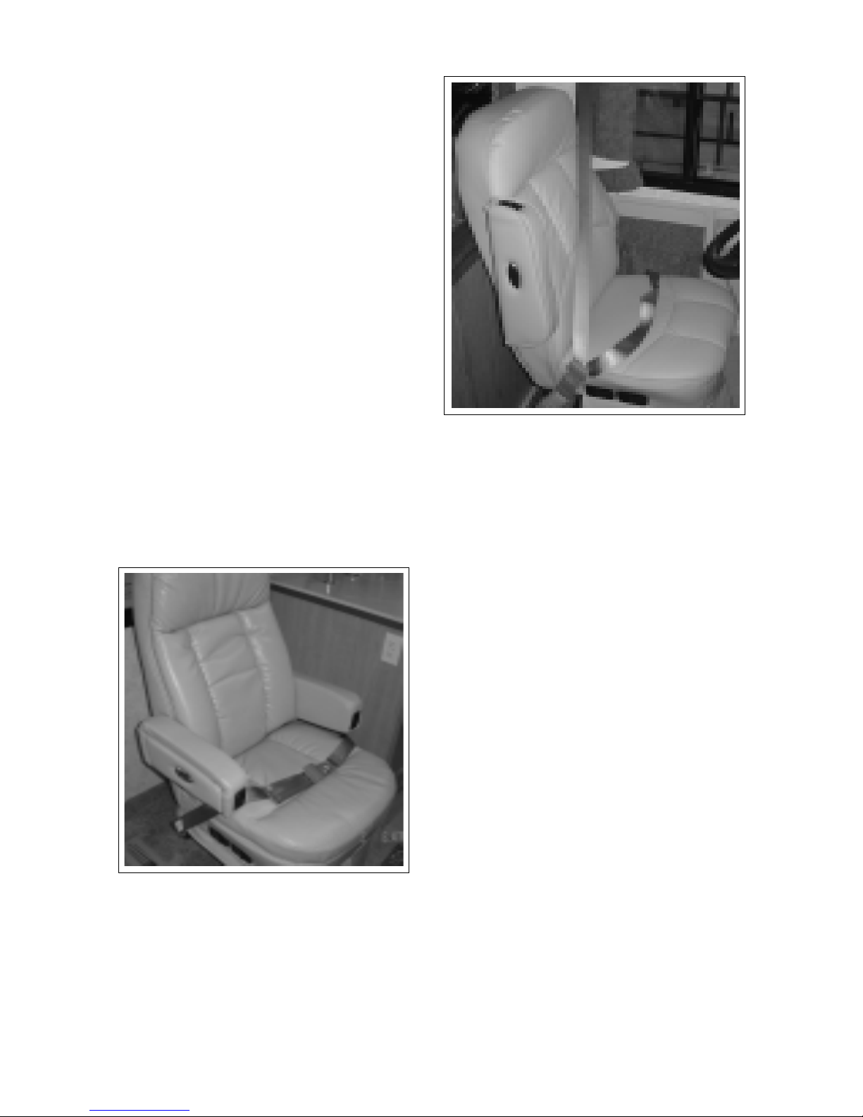
A cocktail chair is located behind the co-pilots seat and
is part of the living room furniture.
1. Swivel Lock:
This latch releases the swivel base. Pull on the
latch to release the lock and allow the chair to
swivel. When the seat returns to this position, the
lock will again engage. Be sure the swivel base is
locked and seat belt fastened if this seat is occupied when travelling.
2. Forward-Back Position:
This Spring-loaded latch releases the lock on the
sliding base to allow the seat to be moved forward
or backward and is located under the seat. Pull on
the latch to release the lock and slide the seat to its
desired position. Release the latch to lock the seat
in posiiton.Several seats are equipped with lap or
lap/shoulder belts and are the only seats approved
for occupancy when travelling. Every occupant
must be seated in one of the approved seats with
the belt fastened whenever the motorhome is
moving. Accident statistics prove the importance
of the need to use seat belts. Vehicle occupants
not seated in an approved seat and restrained with
a seat belt received more injuries of a more serious
nature than those properly restrained.
1
2
Fig. 4-8 COCKTAIL CHAIR
4.6 SEAT/SHOULDER BELTS
Several seats are equipped with lap or lap/shoulder
belts and are the only seats approved for occupancy
when travelling. Every occupant must be seated in one
of the approved seats with the belt fastened whenever the motorhome is moving. Accident statistics
prove the importance of the need to use seat belts.
Vehicle occupants not seated in an approved seat and
restrained with a seat belt received more injuries of a
Fig. 4-9 LAP/SHOULDER BELT
more serious nature than those properly restrained.
Lap/Shoulder Belts:
The driver and co-pilot seats are equipped with a
combination lap and shoulder belt for maximum
restraint next to the front of the unit.
a. Sit in the seat and rotate the seat until it is fac-
ing forward and lthe latch locks in place.
b Pull the spade end of seat belt across the
body and insert it into the buckle. Be sure
the buckle “clicks” to indicate that the spade is
locked securely in place.
c. Be sure the belt is not twisted to minimize
load concentrations during impact. A at belt
distributes impact loads over a wider area of
the body to reduce the chance of injury.
d. Slide the lap portion of the safety belt system
low on the torso to distribute the load across
the hip/pelvis area.
e. Slide the shoulder strap so it lays diagonally
across the chest and shoulder area. Do not lay
it against the neck.
f. Depress the button on the buckle to re-
lease the belt assembly. Hold the belt as it
is released to prevent it from retracting too
quickly.
IMPORTANT
All seat belt retractors are equipped with locks that
engage when the belt moves too fast. Move the spade
end slowly and steadily when fastening to prevent
locking. If belt locks while fastening, release end and
let it retract fully. Then pull again to fasten.
4-5
Page 28
COMMANDER / EMBASSY
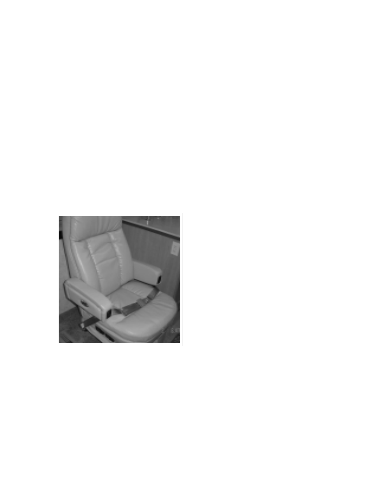
2. Lap Belts:
Only seats equipped with seat belts are approved
for use by occupants while the vehicle is moving.
Never travel in a seat that is not equipped with a
lap or shoulder belt.
a. Sit in the seat and rotate the chair to its
locked position.
b. Pull the spade end of the seat belt across the
lap and insert it into the buckle. Be sure the
buckle “clicks” to indicate that the spade is
locked securely in place.
c. Be sure the belt is not twisted to minimize
load concentrations during impact. A at
belt distributes impact loads over a wider
area of the body to reduce the chance of
injury.
d. Slide the strap low on the torso and touching
the top of the thighs to distribute the impact
load through the hip/pelvic area.
e. Depress the button on the buckle to release
the spade/belt assembly. Hold the belt as it
is released to prevent it from retracting too
quickly.
Pregnant women should wear their lap belts low on
their torsos and shoulder straps diagonally across
their chests. Do not position the strap against the
neck. Wearing a seat or shoulder/lap belt properly will
protect both the mother and the unborn child.
4. Child Restraints:
Child restraint systems are a legal requirement in most
jurisdictions of North America. Statistics prove that
children not secured with a certied child restraint
system experience more severe and more frequent injuries than those properly restrained. In order to provide the safest restraint system for your child during
transport, follow these considerations when selecting
an appropriate child restraint system:
a. Purchase a child restraint system that is labelled
to be certied to all applicable US Motor Vehicle
and Canadian Children's Car Seats and Harness
Regulations.
b. Make sure the system will attach to your vehicle
conveniently and provide safety for your child
every time it is used.
c. Be sure the restraint system is suitable and ad-
equate for your child's age, weight and height.
Check the label for this information.
d. Review the instructions supplied with the child
restraint system. Be sure that anyone placing
a child restraint system in a vehicle fully understands how it must be located, anchored and
used. Improperly placed or anchored restraints
will not provide an acceptable level of safety for
your child.
Fig. 4-10 LAP BELT
3. Pregnancy:
4-6
Page 29
COMMANDER / EMBASSY
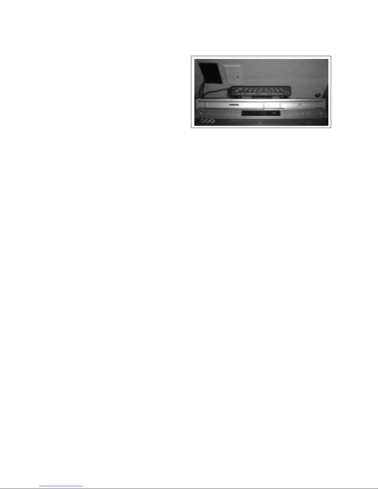
4.7 TV INPUT SELECTOR AND
DVD/VCR COMBO (optional)
Certain pieces of entertainment equipment are
installed inside the front upper cabinets above the
dashboard for convenience and looks.
A. Input Selector:
An input channel selector is located on top of the
DVD/VCR and is used to select a specic signal to
each TV in the vehicle or the VCR.
C
A
TV1
a. ANT:
This push button switch selects the
external antenna as the source of the input
signal to TV 1 or the one mounted in the
front console.
b. AUX:
This push button switch selects the
auxiliary signal, normally cable, as the
source of the input signal to TV 1 or the
one mounted in the front console.
c. VCR:
This push button switch selects the VCR
output as the source of the input signal
to TV 1 or the one mounted in the front
console.
VCR
a. ANT:
This push button switch selects the
antenna signal and directs it into the VCR.
b. AUX:
This push button switch selects the
auxiliary signal, normally the external cable
input, and directs it into the VCR.
B
Fig. 4-11 TV INPUT SELECTOR AND DVD/VCR
This push button switch
B. DVD/VCR:
Refer to the instructions in the Owner's information
package for details. Close the cabinet door when
DVD/VCR access is not required.
C. TV Antenna Signal Booster:
Depress the push button switch to activate the
antenna signal booster for better TV reception.
Depress it again to turn it off.
TV2 a. ANT:
This push button switch selects the
external antenna as the source of the input
signal to TV 2 or the one mounted in the
bedroom.
b. AUX:
This push button switch selects the
auxiliary signal, normally cable, as
the source of the input cable to TV-2
(bedroom).
c. VCR:
4-7
Page 30
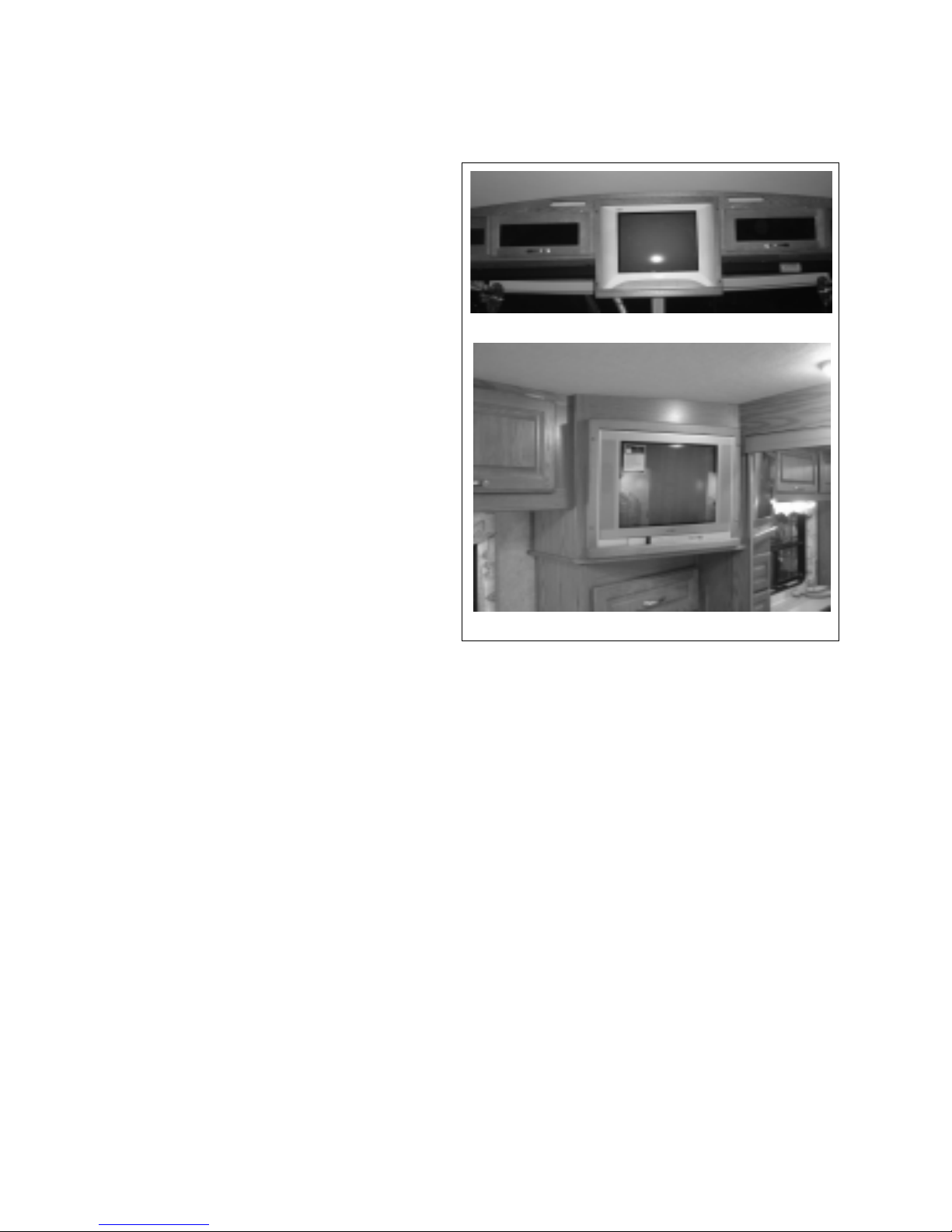
COMMANDER / EMBASSY
4.8 TV's - (OPTIONAL)
Each motorhome may be equipped with a TV in
the cabinet over the dash and an optional
TV in the bedroom. Although it functions
like a standard TV, it is recommended that
the operator's manual in the information
pack be reviewed prior to use. Use in conjunction with the input selector to select the
signal source.
1. Dash TV:
Note - Power to the front TV is disconnect-
ed when the ignition key is turned on.
2. Bedroom TV (optional):
A motorhome may be equipped with a TV
in the bedroom.
Dash TV
Bedroom TV
Fig. 4-12 TV
4-8
Page 31
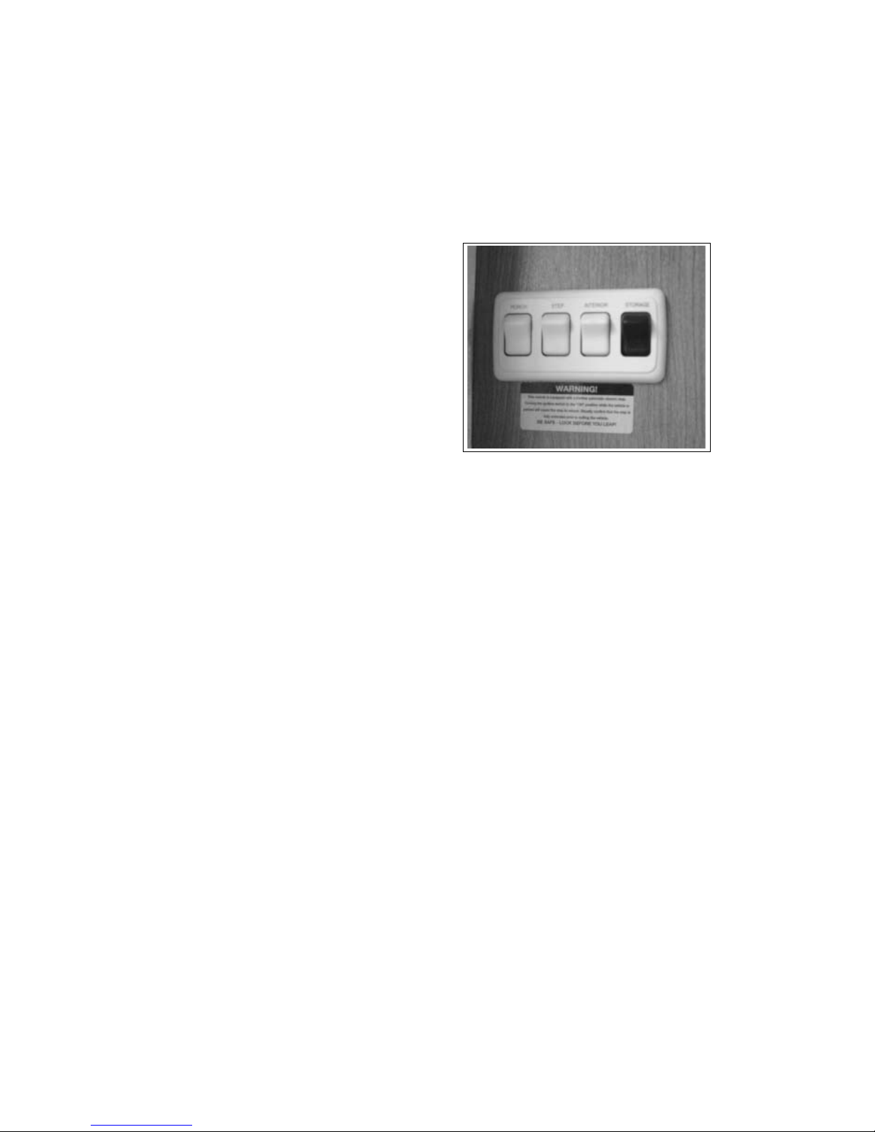
4.9 ENTRANCE DOOR
The entry doorway is equipped with a
switch panel that controls the following
functions:
1. Porch Light:
This 2 position rocker switch con-
trols the power to the outside porch
light. Depress the upper portion of
the switch to turn the porch light on
and the lower portion for o.
COMMANDER / EMBASSY
2. Step Power:
This 2 position rocker switch con-
trols the power to the side entry
step. Depress the upper portion
of the switch to turn the step
mechanism power on and the lower
portion for o. The step will extend
when the door is opened
and retract when the door is closed. Refer to the
Step System Operator's Manual in the information
package for more detailed instructions on step
extension when occupied, “last out” feature and
retraction for driving.
3. Interior Light:
This 2 position rocker switch controls the
power to a coach interior light. Depress the upper
portion of the switch to turn the light on and the
lower portion for o. The switch on the light must
be in the 'on' position.
4. Storage Lights:
This 2 position rocker switch controls the power
to the lights in all the exterior storage compartments. Depress the upper portion of the switch
to turn the power to the lights on and the lower
portion to turn o. This master switch must be
on before any of the light switches in any exterior
compartment will work.
1
2
Fig. 4-14 SIDE ENTRY
3
4
4-9
Page 32
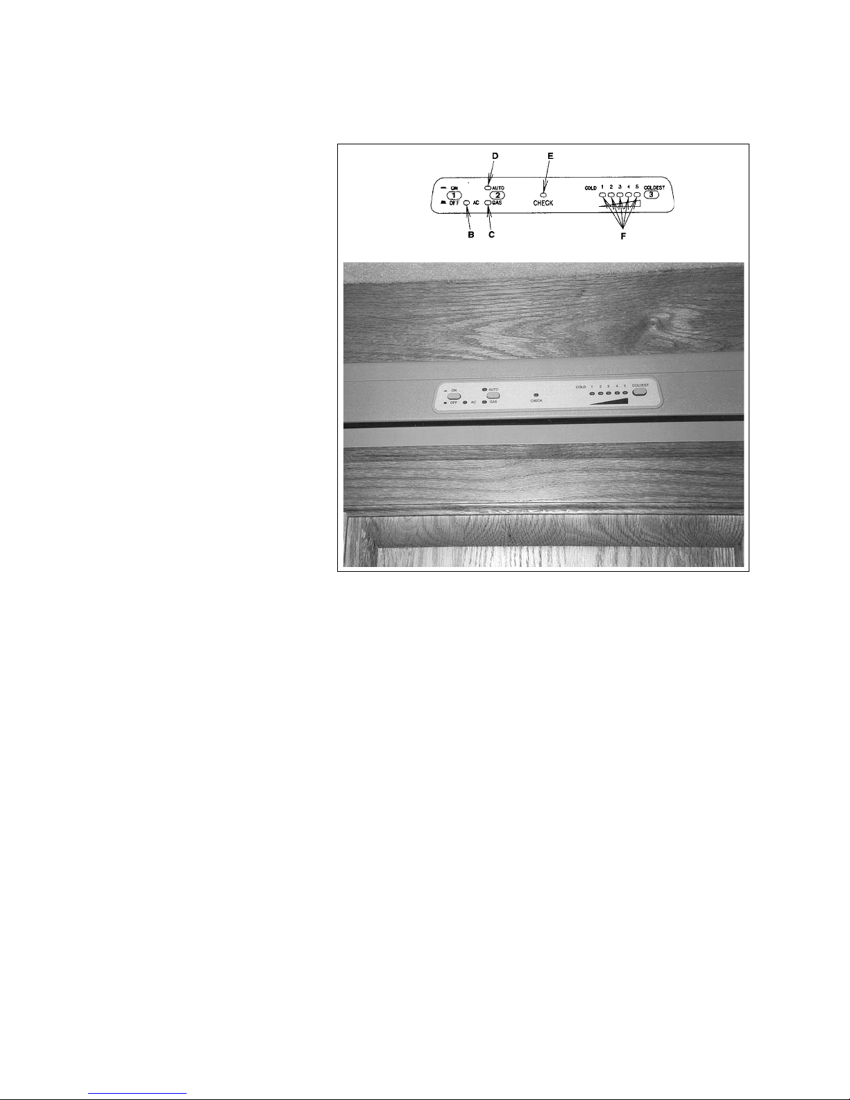
4.10 REFRIGERATOR
The refrigerator control panel is located
directly above the fridge and includes
switches and several indicator lights.
1. Master ON/OFF Switch:
This latching push button switch
controls the power to the refrigerator. Depress the switch and it will
latch in the depressed position for
the power to be on. Depress the
switch again to unlatch it and turn
the power o. The switch will be in
its up position.
IMPORTANT
The control panel operates
on 12 volt DC power. This
requires the coach batteries
to be at full charge for proper
control.
COMMANDER / EMBASSY
Schematic
2. Mode Selector Switch:
This push button switch selects
which power source will be used
to operate the refrigerator. Depress the switch once to select the
AUTO mode and the AUTO indicator light (D) will be lit.
a. If 120 volt power is available, the AC indicator
light (B) will come on and the AC circuit will
operate the refrigerator.
b. If 120 volt power is not available, the GAS
indicator light (C) will come on and the LP gas
system will power the refrigerator.
Fig. 4-15 REFRIGERATOR CONTROL PANEL
IMPORTANT
If the CHECK indicator light (E)
comes on and the GAS indicator
light doesn't come on, the burner
has failed to ignite, turn the system
o and then on again to light the
burner.
Depress the switch again to select the GAS mode and
the LP gas system will provide power to the refrigerator. The GAS indicator light (C) will come on. Refer
to IMPORTANT above if the CHECK indicator light (E)
comes on.
Panel
IMPORTANT
When running the fridge on LP gas,
ensure the shut o value on the LP
tanks are open.
3. Temperature Switch:
This push button selector switch sets the de-
sired refrigerator operating temperature during
operation. Depress the switch once to move the
temperature selection to the next setting. The
indicator lights (F) will illuminate as the selector switch is depressed to identify the operating
temperature selected. Set at the coldest setting
for the rst couple of hours of operation to cool
everything down and then select the mid-range
setting.
Refer to the refrigerator operator's manual in the
information package for more detailed instructions.
4-10
Page 33
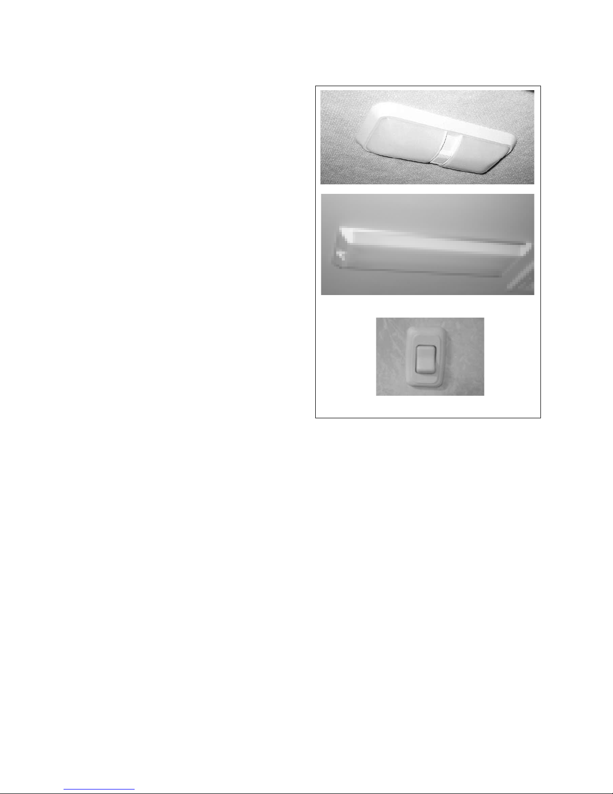
COMMANDER / EMBASSY
4.11 LIGHT SWITCHES
Many rocker, slider or standard light switches are
used throughout the motorhome to turn lights
on and o. If there is any confusion as to which
switch and light work together, try the switch.
Celing
Wall
Fig. 4-16 LIGHT SWITCHES (TYPICAL)
4-11
Page 34
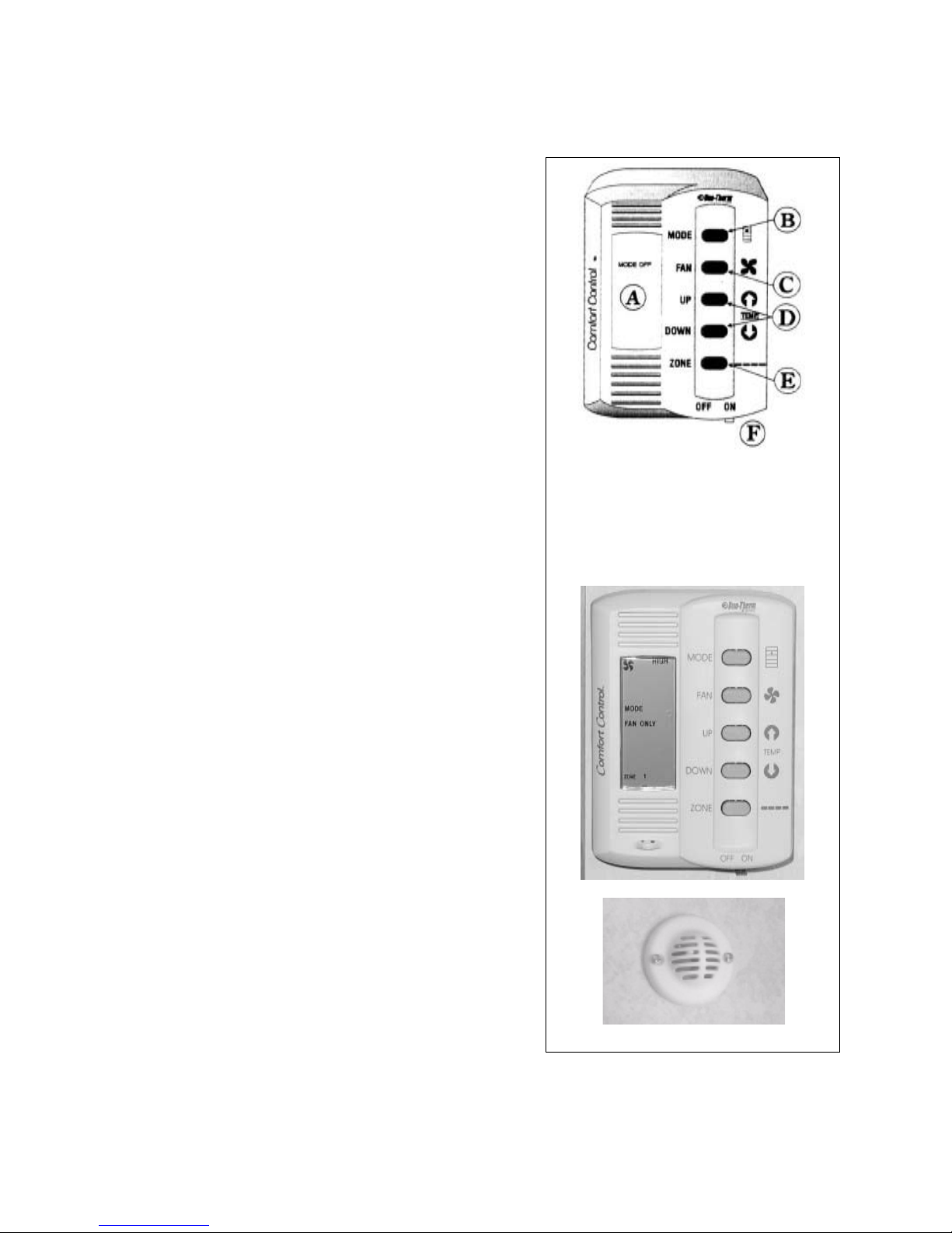
COMMANDER / EMBASSY
4.12 COMFORT CONTROL CENTER
A comfort control center is located in the motorhome (living area
or bedroom) to control the heating and cooling systems in the
vehicle. The control center is customized to the specications of
your vehicle and will control one or more furnaces and air conditioners.
Review the operator's manual in the information package for
detailed operating instructions. The control functions include:
1. Liquid Crystal Display (A):
This liquid crystal display shows the operator the specic
operating parameters of the comfort appliances. The display
will change to reect the varying operating selections by the
user.
2. Mode Selector Button (B):
This push button switch controls the selection of the system
operating mode. Depress the switch momentarily to step
the fan, cool, furnace and heat strip. Depress the switch
again momentarily to move to the next selection. The mode
selected will show in the Liquid Crystal Display.
3. Fan Speeds (C):
This push button switch controls the settings for fan speed
and mode. Depress the switch momentarily to step the fan
through each setting from low, medium, high and auto.
Depress the switch again momentarily to move to the next
setting. The speed selection will show in the Liquid Crystal
Display.
A. Liquid Crystal Display
B. Mode Selector Button
C. Fan Speed Selector Button
D. Temperature Selector Buttons
E. Zone and Stage Selector
F. On/O Switch
Schematic
4. Temperature Selector Buttons (Up and Down) (D):
These push buttons raise or lower the selected system
temperature. Depress the switch momentarily to change the
temperature. Continue to momentarily depress the switch to
change the desired temperate. The selected temperature will
show in the Liquid Crystal Display.
5. Zone and Stage Selector Buttons (E) Commander Only:
These push buttons select the individual zones and stages
for the system. Depress both buttons simultaneously in a
momentary manner to step the control system through its
choice of zones and stages. Zones refer to air conditioner
cooling areas and stages refer to heating areas. The selected
zones and stages will show in the Liquid Crystal Display.
6. On/O Switch (F):
This sliding lever switch is the master ON/OFF switch for the
comfort system. Move the lever to the left to turn o and to
the right for on.
Control
Zone Temperature Sensor
Fig. 4-17 COMFORT CONTROL CENTER
4-12
Page 35
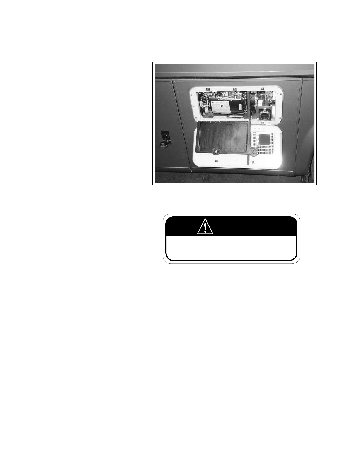
4.13 FURNACE
Each motorhome is equipped with one or
two furnaces depending on the conguration. They are controlled by the comfort
control center. Review the operator's
manuals for the furnace and comfort control centre in the information package for
more detailed operating instructions.
COMMANDER / EMBASSY
Fig. 4-18 FURNACE
WARNING
Do not touch the heater canister and burner exhaust
vent. These components are extremely hot and contact
can cause serious burns.
4-13
Page 36
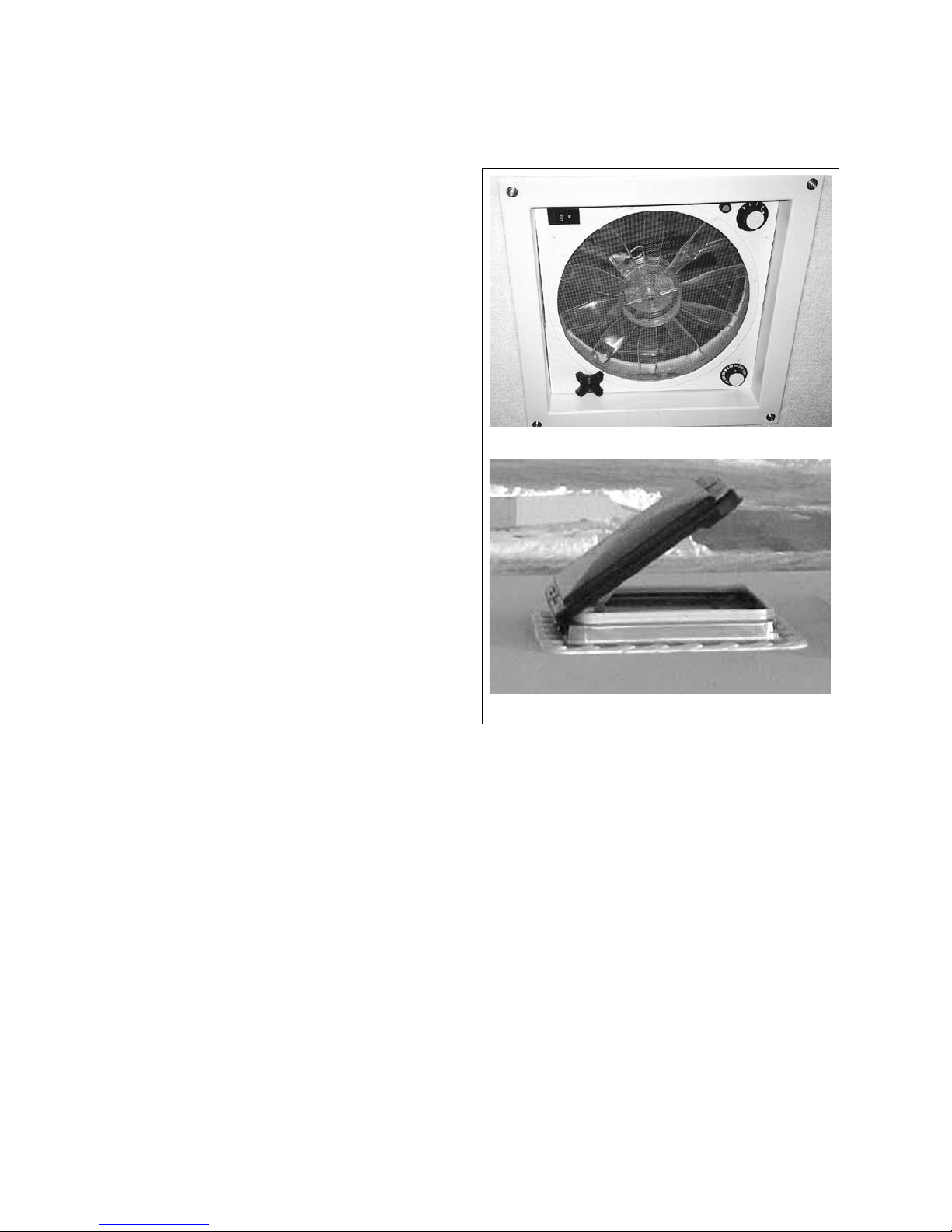
COMMANDER / EMBASSY
4.14 THERMOSTATICALLY CONTROLLED CEILING FAN
(Optional on Embassy)
Your motorhome may be equipped with a thermostatically controlled roof vent with a reversible fan to
provide a controlled air ow through the vehicle. Use
the vent fan in conjunctions with an open window to
provide a ow of fresh air into the unit.
Use these controls:
1. In/Out:
This rocker switch controls the rotational direction
of the fan in the vent. Depress the IN side of the
switch for the fan to draw air into the coach. Depress the OUT side for the fan to blow air out. The
fan must always come to a complete stop before
changing directions.
2. ON/OFF Fan Speed:
This 4 position rotary switch controls the power
to the fan and the fan speed. Turn the switch to
its most counterclockwise position to turn the
fan o. Turn the switch to its rst, second or third
clockwise detents (Position 1, 2 and 3 respectively)
to set the fan speeds at low, medium or high. The
roof vent must be open at least 3 inches or the
internal safety switch will prevent the fan from
coming on.
1
3
2
4
Inside
3. Vent Height:
This knob controls the position of the vent hood.
Turn the knob clockwise to pull the hood down
and close it. Turn counterclockwise to raise or
open the hood.
4. Thermostat:
This rotary switch controls the set point for the
system thermostat. Turn the knob to the desired
position. Moving the pointer to the red portion of
the scale will increase the temperature of the set
point for the vent fan to come on. To operate, the
vent must be open and fan switch turned to either
in or out.
Outside
Fig. 4-19 ROOF VENT - EMBASSY ONLY (OPTIONAL)
4-14
Page 37
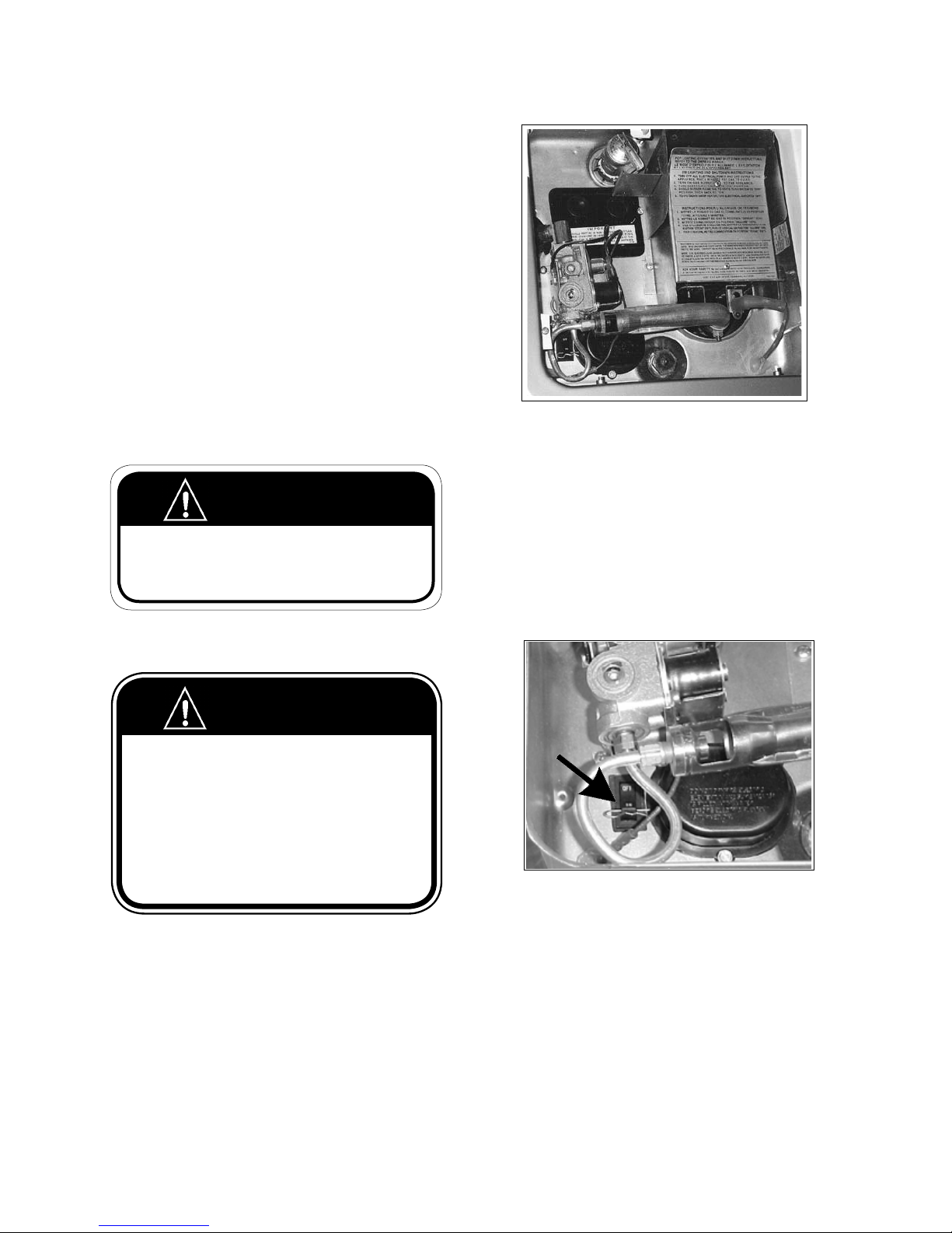
COMMANDER / EMBASSY
4.15 WATER / PLUMBING SYSTEM
A motorhome plumbing system consists of fresh,
grey and black water tanks plus a water heater and
plumbing. Be sure to review, understand and follow
all operating instructions for the system.
4.15.1 WATER HEATER
The water heater is located next to an outside wall
and is only accessible from the outside. All water
heaters are designed to operate using either 120 volt
electric power, LP gas or motor aid. Both electric and
gas power sources require water in the tank before
starting to heat water or the element or tank will burn
out.
A To select electric power:
1. Open water heater access door on the side of
the vehicle.
WARNING
Do not touch the heater canister and burner exhaust vent. These components are extremely hot
and contact can cause serious burns.
2. Remove the click pin lock through the rocker
switch. (Fig. 4-21)
WARNING
IF YOU SMELL GAS
1. Extinguish any open ame, pilot lights and all smoking mate-
rial.
2. Do not touch electrical switches.
3. Shut o thegas supply at the container valve(s) or gas supply
connection.
4. Open doors and other ventilating openings.
5. Leave the area until the odour clears.
6. Have the gas system checked and leakage source corrected
before using again.
3. Depress the on portion of the switch to turn
the power on to the electric heating element.
Fig. 4-20 WATER HEATER
mation Package for more ditailed operating
instructions.
B To select LP gas only:
1. Depress the o portion of the rocker switch
2. Secure the click pin.
3. Turn the water heater switch (located on the
monitor panel) to the 'on' position.
Fig. 4-21 ROCKER SWITCH
C Motor Aid
The motor aid circulates engine coolant through
the heater to heat up the water while traveling.
This will operate at all times when the engine is
running.
IMPORTANT
The electric water heating system will operate when
turned on only when there is sucient 120 volt AC
power available. If there is no or insucient power, the
system will revert back to gas to heat the water.
4. Refer to the operator's manual in the Infor-
4-15
Page 38
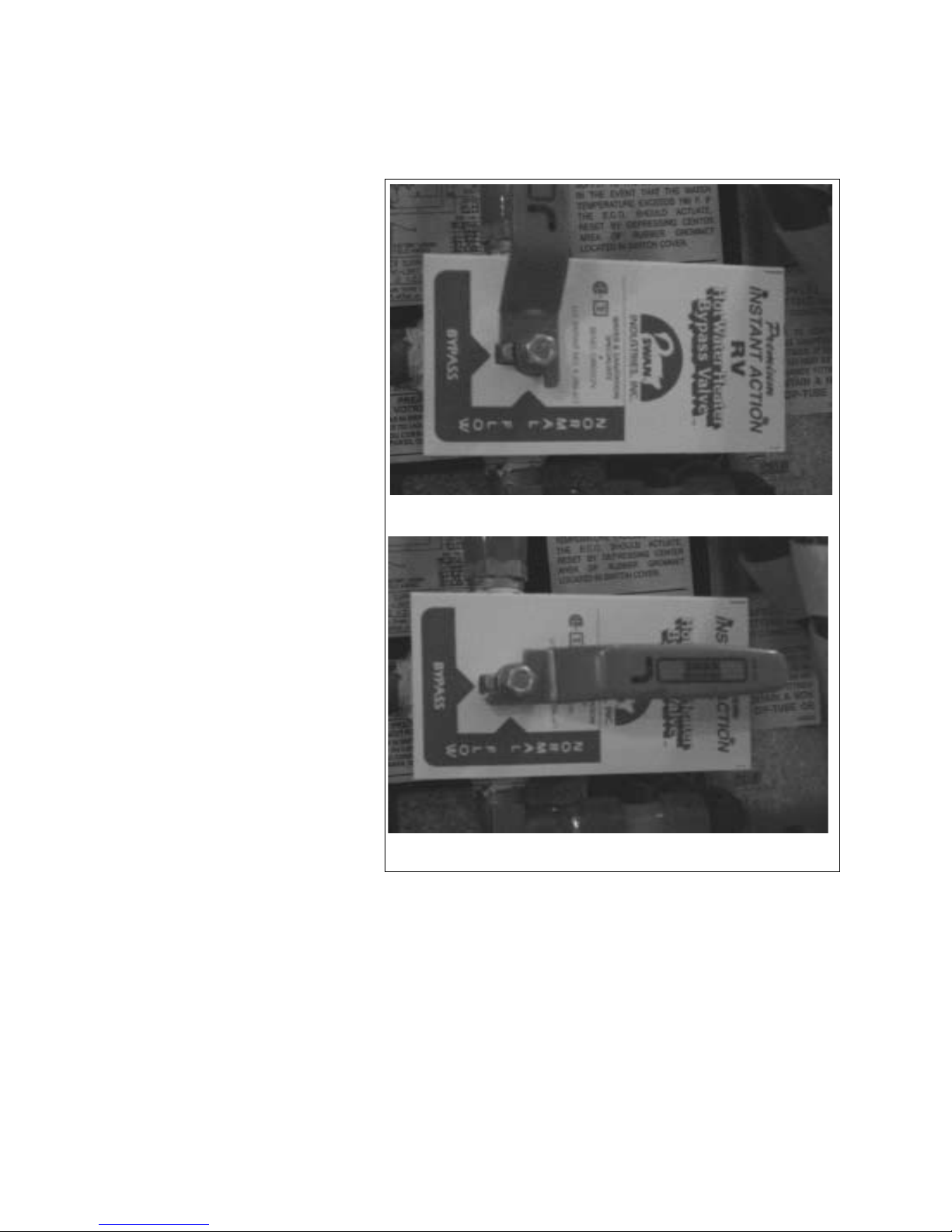
4.15.2 WATER HEATER BYPASS
The water heater is equipped with
a valve that sets its plumbing circuit
for normal or winterize. The valve is
accessed from inside the motorhome.
The location can vary depending on
your specic model
Watch the pointer on the pivot to
determine the valve setting.
1. Normal Operation
2. Bypass Operation
Refer to instruction sheet in information package for more details on
winterizing procedure.
COMMANDER / EMBASSY
1. Normal
2. Bypass
Fig. 4-22 WATER HEATER DIVERTER VALVE
4-16
Page 39
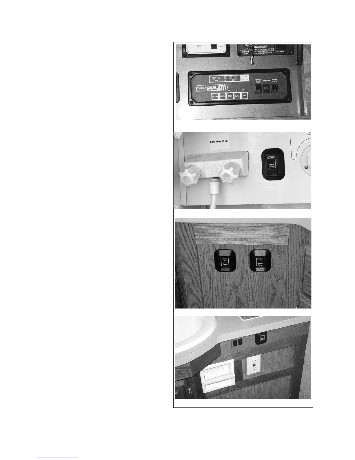
COMMANDER / EMBASSY
4.15.3 WATER PUMP
The water system is equipped with a 12 volt pump
that pressurizes the system and moves water to
where it is required. A master switch is located
above the coach doorway to turn the pump on or o
as desired.
In addition, the Commander is equipped with optional auxiliary switches in the intake compartment,
kitchen and bathroom.
Depress the switch once to turn the pump on and
again to turn it o. Turn the pump on for only as long
as required and then turn o to conserve battery
power.
It is recommended that the master switch be turned
o whenever leaving the motorhome for any period
of time or while driving. A slow leak in a faucet or
connection could drain both the water tank and the
battery.
1
Master
2
Switch locations:
1. Master ON/OFF:
This switch is located on the master control
panel above the coach doorway. The red internal indicator light will come on when this master
switch is on. Depress the top portion of the
switch to turn it on and depress the bottom to
turn it o. This switch must be turned on for any
of the other auxiliary switches to work.
2. Fresh Water Intake
(Varies by model, Commander Only):
This switch is located in the exterior service com-
partment.
3. Kitchen (Commander Only):
This switch is located on the Galley cabinet face
below the countertop.
4. Bathroom (Commander Only):
This switch is located on the Vanity cabinet face
below the countertop.
Water Intake
3
Kitchen
4
Bathroom
Fig. 4-23 WATER PUMP SWITCHES
4-17
Page 40
COMMANDER / EMBASSY
4.15.4 UTILITY COMPARTMENT (COMMANDER ONLY)
Access the water system compartment through the door on the left side of the vehicle. Review the operating
instructions and control functions before trying to use the system.
1. Exterior Shower:
a. Hot Water:
This standard water
tap controls the ow
of hot water to the
shower head. Turn
clockwise to turn o
and counterclockwise
to turn on.
b. Cold Water:
This standard water
tap controls the ow
of cold water to the
shower head. Turn
clockwise to turn o
and counterclockwise
to turn on.
c. Shower Head:
This standard exible hose shower
system
is mounted on the front of the com-
partment. Turn the handle and lift the
head to use it. Turn the collar on the
head to shut o the spray temporarily
to conserve water.
2. Water Fill Selector Valve:
This valve directs the ow of fresh water
into the internal water tank or directly into
the water system and bypass the tank.
Turn counterclockwise to ll the tank and
clockwise to bypass the tank and plumb
directly into the water system.
Fig. 4-24 WATER SYSTEM ACCESS
This tting and cap is the water input tting. Always
install cap when water supply hose is removed.
5. Black Water Tank Flush Fitting:
This tting directs water directly into the black water tank
and can be used to rinse the tank when required. Be sure
the sewer valve (black water tank valve) is open before the
water is turned on.
6. Water System Winterizing Valve:
This diverter valve is used when the water system is being
winterized. Watch the pointer at the pivot point. Move
the handle to its horizontal position for normal operation
and vertical when winterizing the system. Refer to brochure in information package for more detailed instructions.
IMPORTANT
Use pressure regulator between
the outside water supply and the
motorhome to eliminate pressure
surges and spikes.
3. Water Pump Switch:
This switch controls the power to the water
pump. See section 4.15.3 Water Pump for
more details.
4. Water Supply Hose Fitting:
7. Potable Antifreeze Line:
This line is used to draw potable antifreeze into the lines
when winterizing the water system. Normally 1.5 gallons
of antifreeze is required.
8. Water System Pump:
The pump for the water system is mounted in the com-
partment behind this door.
4-18
Page 41
COMMANDER / EMBASSY
b
c
9
a
Fig. 4-25 UTILITY COMPARTMENT
9. Discharge Outlet:
a. Discharge Fitting:
This tting carries the discharge
from the grey and black water tanks.
Connect the discharge line to the
tting and route into an approved
sanitary disposal system. Install dust
cap when the discharge hose is
removed.
b. Black Water Tank Valve:
This is the discharge valve for the
black water tank. Pull out to open
valve and push in to close.
c. Grey Water Tank Valve:
This is the discharge valve for the
grey water tank. Pull out to open
valve and push in to close. Always
empty black water tank rst and
then the grey water. This procedure
will use the grey water to rinse the
discharge sewer hose.
4-19
Page 42
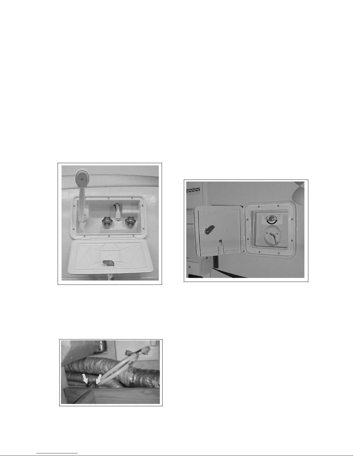
COMMANDER / EMBASSY
4.15.5 WATER SYSTEM (EMBASSY ONLY)
1. Exterior Shower (optional) (Fig 4-26):
a. Hot Water :
This water tap controls the ow of hot water
to the shower head. Turn clockwise to turn o
and counterclockwise to turn on.
b. Cold Water:
This standard water tap controls the ow of
cold water to the shower head. Turn clockwise
to turn o and counterclockwise to turn on.
c. Shower Head:
This standard exible hose shower system is
mounted on the front of the compartment.
Turn the handle and lift the head to use it.
Turn the collar on the head to temporarily shut
o the water spray.
c
1
a
b
a. Water Fill Selector Valve:
This valve directs the ow of fresh water
into the water tank or directly into the water
system and bypass the tank. Turn counterclockwise when lling the tank and clockwise
to bypass the tank and plumb directly into the
water system.
b. Water Supply Hose Fitting:
This tting and cap is the water input tting.
Always install cover when water supply hose is
removed.
IMPORTANT
Use pressure regulator between
the outside water supply and the
motorhome to eliminate pressure
surges and spikes.
a
2
Fig. 4-26 EXTERIOR SHOWER
Note: The Exterior Shower is equipped with
two shut o valves to shut o the hot and cold
water to the exterior shower for cold weather
use. See section 17 for Winterization procedure.
2. Fresh Water Tank Fill
b
Fig. 4-28 WATER FILL SELECTOR
Fig. 4-2 EXTERIOR SHOWER
SHUT-OFF VALVES
4-20
Page 43
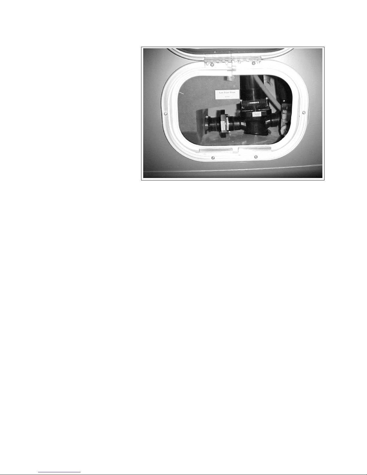
3. Black and Grey Tank Discharge
Valves:
a. Black Water Tank Valve:
This is the discharge valve
for the black water tank.
Pull out to open valve and
push in to close. Always
empty black water tank
rst.
b. Grey Water Tank Valve
This is the discharge valve
for the grey water tank. Pull
out to open valve and push
in to close. Always empty
black water tank rst and
then the grey water. This
procedure will use the grey
water to rinse the discharge
sewer hose.
COMMANDER / EMBASSY
3
Fig. 4-29 DISCHARGE VALVES
b
a
4-21
Page 44
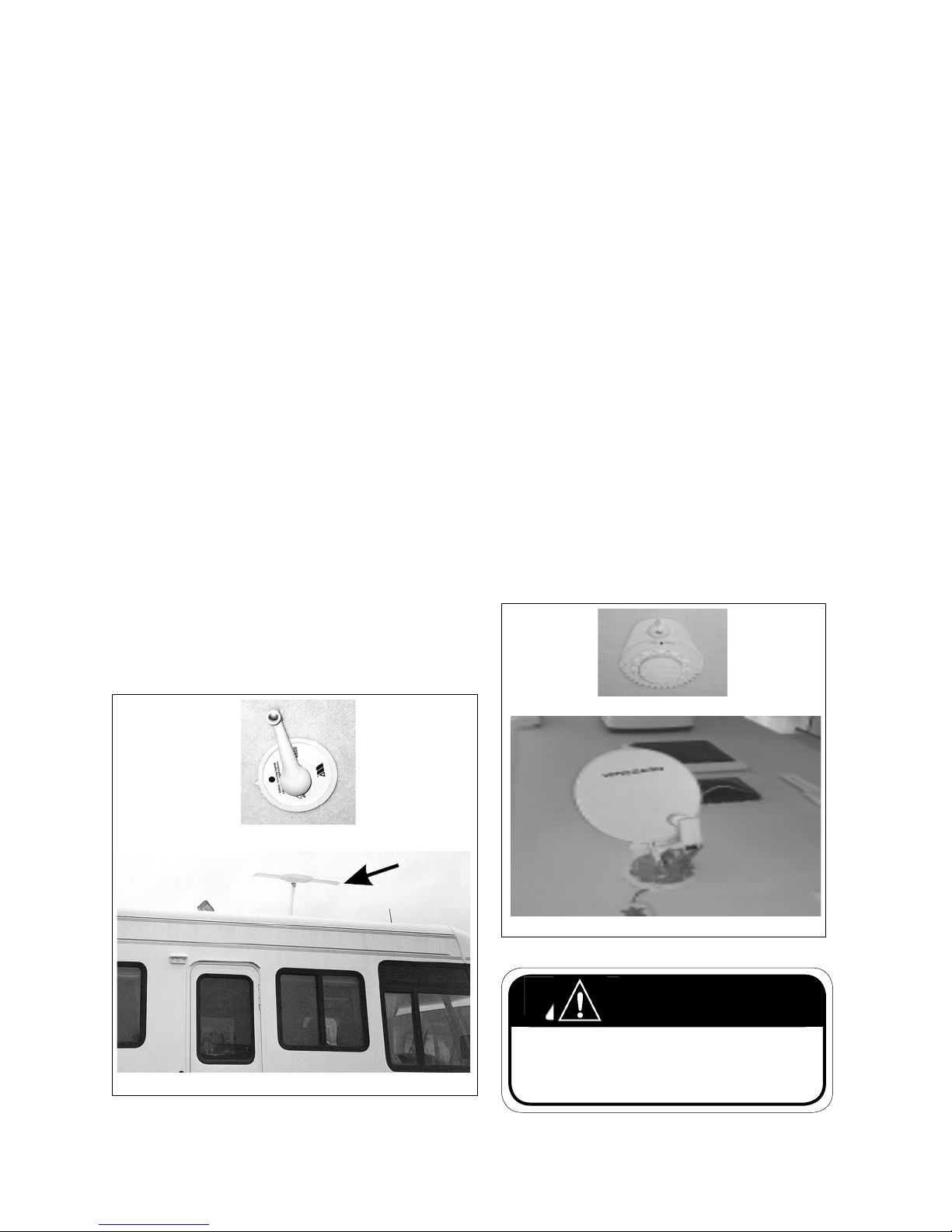
COMMANDER / EMBASSY
4.16 TV ANTENNA
Each motorhome is equipped with an extendable TV
antenna on top of the unit to provide reception at
remote locations. Always fully retract antenna whenever vehicle is moved or transported.
1. Extending and Retracting:
This crank controls the position of the antenna
assembly on top of the roof. Turn the crank
clockwise to raise the antenna and counterclockwise to lower. Always fully extend or retract
the antenna. Do not move or travel when the
antenna is extended. If parking where debris
can accumulate on roof, clean the antenna area
before retracting.
2. Rotation:
The antenna can be rotated to align with the
signal to provide the best reception. Grasp the
crank handle mounting plate on both sides and
pull down. Rotate the plate (antenna) until the
antenna is set to provide the best TV reception.
Always watch the reception on a TV to know
when the reception is the best. Always rotate
the antenna back to its storage position by
aligning the pointer on the plate to the reference
mark before lowering it.
4.17 SATELITE DISH (optional)
The optional Satelite dish is located on top of the
unit to provide T.V. reception via Satelite signal. Always fully retract the Satelite dish whenever vehicle
is moved or transported.
1. Extending and Retracting:
This crank controls the position of the Satelite
receiver assembly on top of the roof. Turn the
crank clockwise to raise the Satelite dish and
counterclockwise to lower it. Do not move or
travel when the Satelite dish is raised. If parking
where debris can accumulate on roof, clean the
Satelite dish area before retracting.
2. Rotation:
The Satelite dish can be rotated to align with
the signal to provide the best reception. Always
rotate the Satelite dish back to its storage position by aligning the pointer on the plate to the
reference mark before lowering it. Refer to the
manufacturer's manual for operating instructions and maintenance information.
Control
Antenna - Up
Fig. 4-30 TV ANTENNA SYSTEM
Control
Satelite Dish - Up
Fig. 4-31 SATELITE DISH SYSTEM
WARNING
Do not travel with the Antenna or Satelite Dish in
the "UP" position. This could cause major damage
to the roof, or roof top equipment.
4-22
Page 45
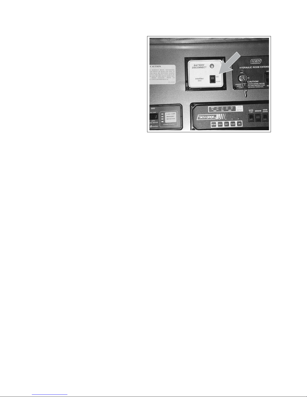
COMMANDER / EMBASSY
4.18 BATTERY DISCONNECT
This switch located above the coach doorway
disconnects the coach batteries from the electrical system when the motorhome is in storage to
prevent battery discharge.
Depress the upper portion of the switch to connect the batteries into the electrical system for
normal operation and the indicator light will be
illuminated. Depress the bottom portion of the
switch to disconnect the battery for storage to
prevent battery drain. The indicator light will not
be lit.
Fig. 4-32 BATTERY DISCONNECT (COMMANDER)
4-23
Page 46
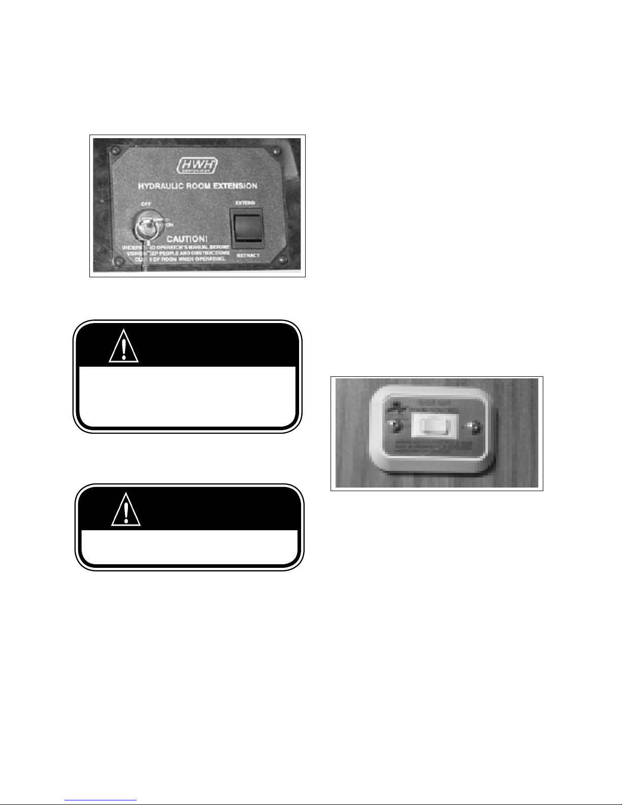
COMMANDER / EMBASSY
4.19 SLIDE-OUT ROOM (SLIDE-OUT EQUIPPED MODELS ONLY)
1. Control Panel (Main or Galley Slides):
This panel controls the operation of the Main or
Galley slide-out room. Review the extend/retract
procedure before operating these controls.
b. Extend/Retract:
This spring-loaded to center neutral rocker
switch controls the movement and direction
of the slide-out room. Depress and hold the
top portion of the switch to extend the room.
Depress and hold the bottom portion of the
switch to retract the room. Release the switch
for it to return to centre and the room will
stop moving.
a
Fig. 4-33 MAIN & GALLEY SLIDE
CONTROL PANEL
b
WARNING
Make sure travel locks are removed before extending
the slide-out.
Make sure travel locks are fastened securely before
moving the motorhome.
CAUTION
Extend levelling jacks on to a rm supporting base
and level unit before extending room.
WARNING
Keep People clear of room while in operation. Make
sure room area is free of obstacles.
a. Key Switch:
This key switch controls the power to the
pump that supplies pressurized oil to the
hydraulic cylinders that extend and retract the
room. Always turn the switch o unless moving the slide-out room. See operating instructions in the Owner's Information Package.
IMPORTANT
Release the switch when the extend/retract cylinders
reach the end of their stroke. The pressure of the hy-
draulic circuit will change when the cylinders reach the
end of their strokes and the pump sound will change.
Release the switch when the sound changes.
2. Control Panel (Bedroom & Wardrobe Slide):
This panel controls the operation of the Bedroom
or Wardrobe slide. Review the extend/retract procedure before operating these controls.
Fig. 4-34 BEDROOM AND WARDROBE SLIDE CONTROL
SWITCH
Extend/Retract:
This spring-loaded to center neutral rocker
switch controls the movement and direction
of the slide-out room. Depress and hold the
'out' side of the switch to extend the room.
Depress and hold the 'in' side of the switch to
retract the room. Release the switch for it to
return to centre and the room will stop moving.
4-24
Page 47
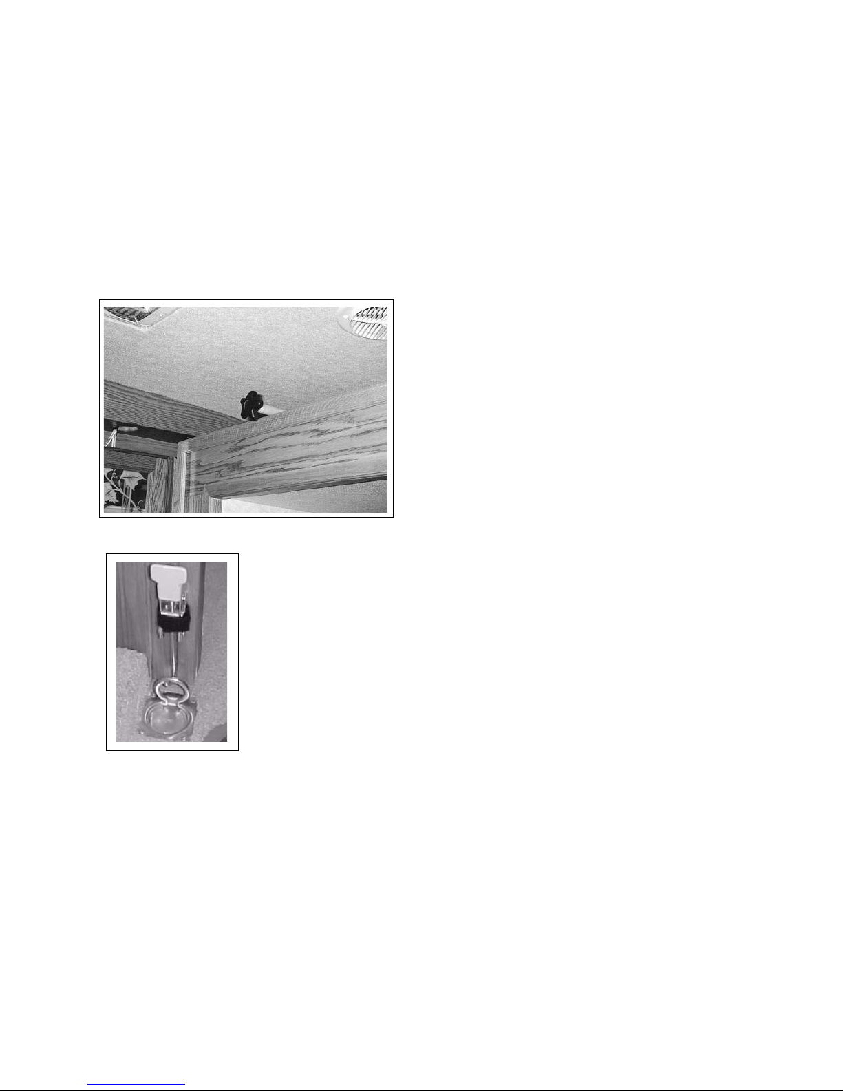
COMMANDER / EMBASSY
3. Slide-Out Room Locks:
This slide-out room assembly is designed with locks
that hold it securely in place for transport. Top
mounted locks are located on the top of the room,
one at each end, Floor mounted locks are located on
the oor. Turn clockwise to secure lock and counterclockwise to release. Always secure locks whenever
room is retracted prior to moving the motorhome.
Fig. 4-35 TRAVEL LOCKS (top mounted)
Fig. 4-36 TRAVEL LOCKS (Floor mounted)
NOTE
Refer to section 9.3 for detailed operating
instructions.
4-25
Page 48
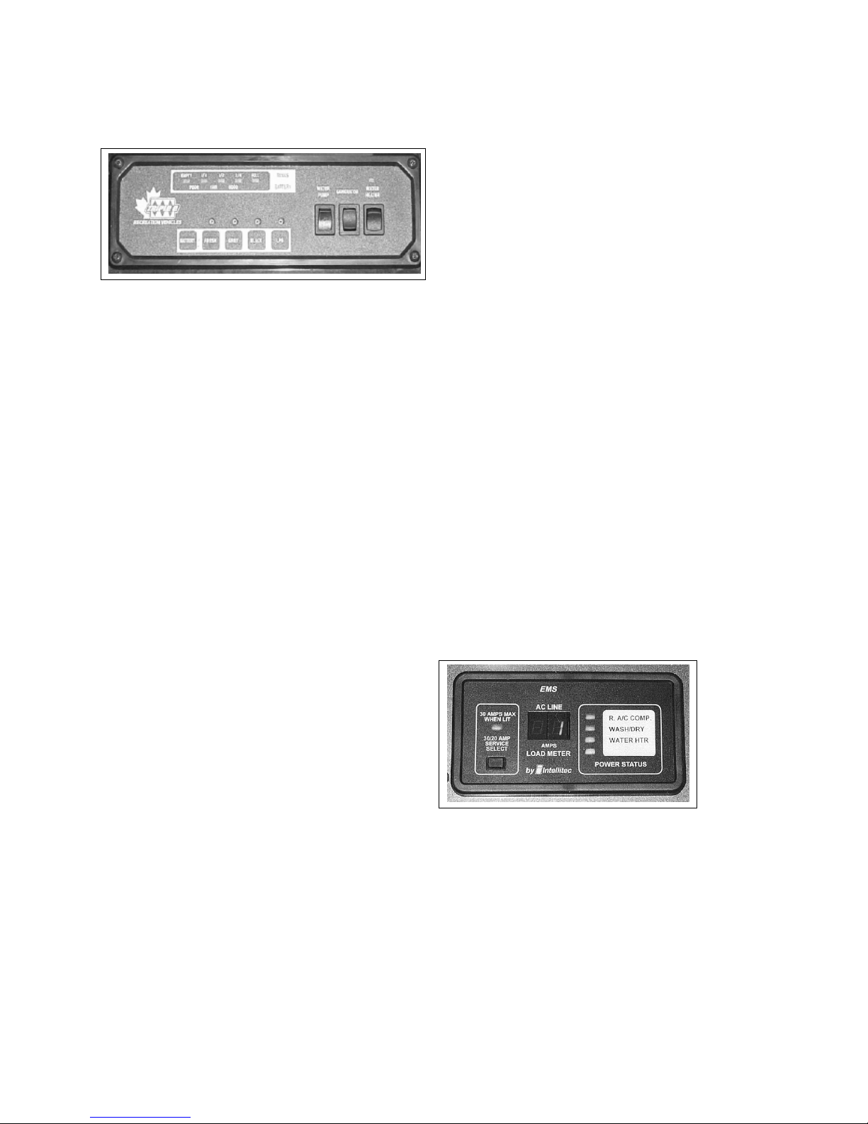
COMMANDER / EMBASSY
4.20 SYSTEM MONITOR
A system monitor is located aboce the entrace door-
way.
1
5. Water Heater:
This rocker switch controls the electrical power to
the water heater igniter. Depress the top part of
the switch and the water heater will ignite. The
red light in the switch will go o when the burner
ignites.
2
Fig. 4-37 SYSTEM MONITOR
1. Status LED's:
Five LED's are used to indicate the status of the
tanks and battery. The tank scale registers EMPTY,
1/4, 1/2, 3/4 or FULL. The battery charge condition
registers POOR, FAIR and GOOD. Read the appropriate scale when the battery or tank switches are
depressed.
2. System Switches:
Each system is equipped with a switch to activate
its own monitoring system. Depress and hold the
switch. The system condition will be shown by the
LEDs above.
a. Coach Battery
b. Fresh Water Tank
c. Grey Water Tank
d. Black Water Tank
e. LP Gas Tank
3. Water Pump Master:
This rocker switch controls the power to the water
pump. Depress the top of the switch to turn the
power to the pump on. A red light in the switch
will come on when the power is on. Depress the
bottom of the switch to turn o and the light will
go o. When the power is on, the auxiliary water
pump switches can be used to turn the pump on
and o (Commander only). See 4.15.3 for more
information.
4
3
5
The red light will remain on if the burner fails to
ignite.
4.21 ENERGY MANAGEMENT SYSTEM
(EMS) OPTIONAL
This system prioritizes and distributes the power from
the shoreline or generator to the appliances or other
120 V users. This system disconnects selected “postpone-able” power draws to eliminate or minimize the
tripping of circuit breakers. The selected power draws
are automatically turned back on when the higher
priority power requirement is over.
The control panel is located above the coach entry doorway and the monitoring microprocessor is
mounted in the electrical AC breaker box. No setting
or adjusting by operator is required.
Normally the postpone-able power draws are the air
conditioner, washer/dryer and electric water heater.
Each will be shut down as other demands increase.
Refer to the booklet in the information package for
more details.
4. Generator:
This 3 position rocker switch controls the power to
the auxiliary generator.
a. Starting:
Depress the top portion of the switch against
the spring load to engage the starter and
start the engine. Release the switch when the
engine starts and it will return to the run posi-
tion.
b. Stopping:
Depress the bottom portion of the switch and
hold until the generator stops. Release the
switch.
Fig. 4-38 EMS Control Panel
4-26
Page 49
COMMANDER / EMBASSY
5 DRIVING
Always review the chassis manual before starting or
moving your motorhome.
5.1 PRE-TRIP INSPECTION
1. Be sure all equipment is serviced and ready for
travel.
2. Inspect wheel lugs for tightness (See Chassis
manual for torque requirements). Examine all
tires for road damage. Ensure that all tires are
inated to proper pressure. (See Department of
Transport sticker located on the drivers door inside
panel(Commander) on the sidewall to the left of
the drivers seat(Embassy)).
3. Check All Fluids:
a. Engine/Crankcase Oil
b. Transmission Fluid
c. Power Steering Fluid
d. Radiator Recovery System
e. Reservoir Level
f. Battery Electrolyte Level
g. Windshield Washer Reservoir
h. Slide-Out Hydralic Reservoir
10. Fill LP gas container to 80% full. Be careful not to
overll. An overlled LP gas container will cause
the gas regulator to fail, and may result in problems with LPG components. Turn o LP gas valve
on LP container. Make sure all LP gas controls are
turned o (Furnace, Oven, Fridge). Check for LP
gas leaks regularly using soapy water.
WARNING
All pilot lights and appliances shall be turned o
during refuelling of motor fuel tanks and/or propane
containers.
Do not smoke when refuelling.
11. Check that sewer connections are properly stored
and all external compartments are closed and/or
locked.
12. Close and latch all doors and drawers, and secure
all loose objects (including refrigerator contents).
13. Retract all Slide-Out rooms and secure travel locks
in place.
4. Check oil level in generator power plant (if installed). Refer to Instruction and Maintenance
Manual provided by the generator manufacturer
for other pre-use requirements.
5. Consult Chassis Manual for recommended list of
system checks.
6. Check to see that all lights are in working order.
7. Check the engine compartment for animals.
Animals and pets like the warmth of the engine
compartment and could become entangled in the
moving parts.
8. Sanitize and ll fresh water tank if required. Turn
o the water pump. (Unless water is needed). The
water pump should also be turned o when leaving the unit for any length of time.
9. Start the refrigerator a day ahead of time so it will
be cold for your trip.
14. Deodorize waste holding tank. (See Section 12.2.3
for details).
15. Check that all blocks and chocks are removed and/
or stowed.
16. Check that there are no obstructions in the motorhome pathway when it moves. Be sure there
is proper clearance between adjacent objects to
prevent contact.
17. Disconnect and stow shoreline.
18. Check to ensure that the re extinguisher is in
good condition and fully charged.
5-1
Page 50

COMMANDER / EMBASSY
5.2 EMERGENCY EQUIPMENT CHECK LIST
Use this list as a guide to identify the minimum
amount of emergency or safety equipment. Take more
as appropriate for your travel or personal needs.
are snug. All passengers should be in a seat that
is equipped with a seat belt. All pregnant riders
should be in a seat equipped with a shoulder strap
for maximum safety.
1. First Aid Kit
2. Emergency Flares
3. Tool Box and Tools
4. Plastic Bucket
5. Tow Rope or Chain
6. Wheel Blocks or Jacks
7. Water Hose
8. Electrical Cord Extension (100-150 ft./minimum 3
wire/30 amp)
9. Fire Extinguisher
5.3 BEFORE DEPARTING
1. Retract side door steps. Be sure automatic step
retract system is turned on to retract step when
side door is closed.
2. Check that TV antenna is retracted, stowed and
secured.
3. Check that room extension is fully retracted and
travel locks are in place if so equipped.
4. Fully retract and lock vehicle levelling jacks (if so
equipped).
11. Small children should always be strapped into a
car seat facing rearward.
12. Do not carry any passengers unless they are in
a seat equipped with a seat belt and the belt is
fastened.
5.4 ENGINE OPERATION
Refer to the chassis manufacturer manual for engine
starting and stopping instructions.
5. Secure all objects in vehicle. Tie, latch or lock all
loose objects as appropriate. Unsecured objects
can become a dangerous projectile in a sudden
manoeuvre or accident.
6. Securely close and lock all doors to prevent intruders and minimize the chance of a door coming
open in an accident.
7. Lock the driver and passenger seats in the forward
facing direction.
8. Adjust the rearview mirrors to provide the best
rearward visibility.
9. Set the drivers seat to provide the desired leg to
pedal spacing for your personal comfort.
10. Fasten seat belts low on the torso and be sure they
5-2
Page 51

COMMANDER / EMBASSY
5.5
1. Controls:
The motorhome driver controls are automotive
2. Handling:
The motorhome power-to-weight ratio is lower
3. Mountain Driving:
When driving in hilly or mountainous terrain you
a. Climbing a Hill:
The transmission is designed to down-shift
DRIVING CHARACTERISTICS
type and the steering and braking controls are
power assisted to help make driving as comfortable as possible. However it must be remembered
that the motorhome is much higher, wider and
heavier than a family automobile.
than that of the average automobile. Therefore
it is essential to compensate for less acceleration
when moving into trac or when passing another
vehicle. Allow extra room to turn a corner and to
change lanes. When going underneath a bridge
or similar overhang be sure you have sucient
clearance. Although you should check your vehicle spec. sheets, if you have any questions measure the unit. Do not take chances. Leave at least 6
inches of clearance.
should employ dierent driving techniques than
those used when driving under at road conditions.
automatically when required during a longer
uphill climb. If you nd that the transmission shifts up and down rather frequently, it
is a good idea to select a lower gear for the
duration of the climb to prevent this repeated
shifting. This will prevent unnecessary wear
and tear on your transmission.
b. Descending a Hill:
It is a good idea to select a lower gear on
your transmission when descending a hill to
avoid prolonged application of the brakes.
Extended application of the brakes can cause
unnecessary wear and tear and overheating.
Under extreme conditions this could cause
you to lose control of the vehicle.
A STANDARD RULE OF THUMB:
Use the same lower gear position when
descending a hill as you used while climbing
the hill.
5.6 DRIVING SAFETY TIP
1. When backing the motorhome, have a person
stand to the rear on the driver's side to guide you.
2. Before departing on the trip, check your routes.
Remember, some tunnels prohibit motorhomes
with LP gas systems.
3. While travelling, make sure all occupants use their
seatbelts.
4. While travelling, make sure all doors are closed
and locked and that cabinets, drawers, and loose
objects are secure.
5. Instruct your family on what to do in case of re,
and hold re drills periodically.
6. Maintain proper charge in the re extinguisher.
Inspect the re extinguisher periodically.
7. Carbon Monoxide and smoke detectors should
not be obstructed and should be in working order
at all times. Check battery every month.
CAUTION
Observe the engine temperature carefully especially during long climbs. If you notice
over-heating, pull o the road
and allow the engine to cool o
thoroughly before you continue.
Fill the recovery tank with coolant if necessary.
8. Keep a well stocked rst aid kit handy.
9. Keep a tool box handy.
10. Check tire condition and pressure often while
travelling. Pay special attention to inside rear duals. Make it a habit to check tire pressures before
each trip, and each time you refuel.
5-3
Page 52

COMMANDER / EMBASSY
5.7 TRAVEL TIPS
As you travel with your motorhome you will learn
much from your own experiences. Share with other
motorhome owners and learn from them. Read RV,
outdoor and camping magazines for camping and
travel tips. Here are a few basic suggestions to make
your travel and your camping easier and more enjoyable:
1. Know the height and width of your motorhome. Make adequate allowance for clearance.
2. Always ll your water tank with clean, fresh, potable water. Do not use a new hose to ll the tank. It
may leave a taste of rubber or vinyl.
3. Conserve water especially when showering. The
holding tanks have a limited capacity.
4. Dump sewage only at approved dumping sites.
5. Store all liquids in plastic containers with tight
seals.
6. Watch the levels in your holding tanks. Dump
regularly to avoid unnecessary build-up and
potential odor. After dumping, make sure to add
water to the black water tank to prevent solids
from settling in the tank. Without adequate liquid
in the black water tank, dumping can be dicult, if
not impossible.
7. Make sure all compartment doors and refrigerator
and freezer doors are closed securely. Open these
doors carefully after travelling. The contents may
have shifted while travelling.
8. There are legal restrictions in some jurisdictions
regarding vehicles with LP gas containers driving
through highway tunnels. Check your route carefully as you travel.
9. Be careful not to leave odor-causing food or materials in your motorhome for extended periods of
time. Make sure wet clothing and towels are dry
before storing.
10. Make sure your re extinguisher is ready for use
and that you know how to operate it.
11. While driving, use your mirrors to determine
whether you are crowding the center line or the
outside edge of the highway. Remember, you are
driving a vehicle that requires a driving style quite
dierent from driving the family car.
5-4
Page 53

COMMANDER / EMBASSY
5.8 QUICK LOADING CHECK-LIST
1. Bedding:
a. Sleeping Bag
b. Sheets
c. Pillow Cases and Pillows
d. Mattress Pads
e. Extra Blankets
f. Laundry Bags
2. Cooking:
a. Can Opener
b. Bottle Opener
c. Aluminium Foil
d. Matches
e. Plastic Bags
f. Coee Pot
g. Storage Dishes
3. Cleaning:
a. Scouring Pads
b. Cleanser
c. Glass Cleaner
d. Dish Soap
e. Sponge
f. Laundry Soap
g. Cleaning Rags
h. Paper Towels
i. Garbage Bags
6. Personal:
a. Credit Cards
b. Traveller's Checks
c. Cash
d. Driver's License
e. Birth Certicate
f. Sunglasses
g. Vehicle Registration
h. Insurance Policies
7. Pet Needs:
a. Food
b. Leash
c. Feeding Trays
d. Vaccination Record
8. Miscellaneous:
a. String
b. Clothesline
c. Insect Repellent
d. Tape/Masking/Duct
9. Additional Items as per Individual and Personal
Tastes and Needs:
_____________________________________________
___________________
4. Bathroom:
a. Bath/Hand Soap
b. Bath Towels/Beach Towels
c. Toiletry Kits
d. Tooth Brushes/Toothpaste
e. Shaver/Razor
f. Toilet Tissue
5. Baby Needs:
a. Car Seat/Child Restraint
b. Portable Crib
c. Play Pen
d. Mattress Pads
e. Extra Blankets
f. Laundry Bags
__________________________________________
_________________________________________
_____________________________________________
___________________
__________________________________________
_________________________________________
_____________________________________________
___________________
__________________________________________
_________________________________________
_____________________________________________
___________________
5-5
Page 54

COMMANDER / EMBASSY
5.9 SEVERE WEATHER INFORMATION
As a motorhome traveller you will nd the desire to explore new and out-of-the-way places irresistible. These
recreational areas can be vulnerable to unusual and severe weather conditions that could endanger your safety.
A few suggestions and safety precautions may help in case you ever nd yourself in this situation.
IMPORTANT
All motorhome occupants
should be familiar with these
safety precautions and be alert
to changes in the weather.
1. Be alert! Thunderstorms and heavy rains can occur
suddenly and unexpectedly. Listen frequently
to weather reports for the area in which you are
camping or travelling.
2. When camping near a stream or any body of
water leave plenty of space between your motorhome and the stream.
3. Avoid canyons or dry washes during threatening
weather. Prepare with an alternate exit. Move to
higher ground as soon as it starts raining.
4. Should you get caught in a ash ood, do not
attempt to move your vehicle. Abandon it and
return to it only after the water has gone down.
Never attempt to drive through any ooded area.
5. Heed the warnings and instructions of local authorities.
6. Have on hand enough survival supplies for several
days. This should include food, water, rst-aid
supplies and necessary medications.
8. Remember These Terms:
a. Weather Watch:
Severe weather may develop in your area. Be
prepared for an emergency.
b. Weather Warning:
Severe weather is occurring or is imminent.
Find a safe location immediately.
It is always a good idea when in new and
strange territory, to listen to weather information on your radio or TV from time to time so
that you will not be caught unaware if and
when there is a sudden change in the weather.
7. When you leave home, inform someone of your
destination and your schedule. Notify the same
people if and when your plans change.
5-6
Page 55

COMMANDER / EMBASSY
6 SAFETY EQUIPMENT OPERATION
Triple E has made every eort to design the vehicle to promote safe driving, use and occupancy. In addition, it
has several pieces of safety equipment that the drivers and users should be aware of and trained in their use.
Review these instructions with all new people prior to using the motorhome.
6.1 FIRE PREVENTION
Fires can be started in a variety of ways within your vehicle including but not limited to careless smoking, malfunction of appliances or equipment, ammable material on hot surfaces, etc. Fires are best prevented rather
than put out. Prevent but anticipate what to do if they occur. Review the following sections with everyone on a
regular basis.
6.1.1 FIRE SAFETY TIPS
1. Establish and maintain good housekeeping practices. Never allow combustible materials to accumulate. Make sure you store ammable liquids
in approved containers in a well-ventilated space.
2. Make sure you have charged re extinguishers
readily accessible.
3. Avoid using ammable products in the motorhome.
4. Never smoke in bed or when relaxing on the
couch.
5. Do not overload electrical outlets.
6. Do not leave cooking food unattended.
7. Keep children away from electrical outlets and LP
gas controls.
8. Never use matches to check for LP gas leaks. If
there is a re, get everyone out of the motorhome.
If possible, use your re extinguisher. Close all
LP gas valves if possible. Call the re department
and stay a safe distance away from your unit. Do
not re-enter your motorhome until the re ofcials declare that its safe to do so.
9. Formulate a plan for escape from the vehicle
should an emergency arise. It is particularly
important that the escape plan be rehearsed with
everyone, especially children, who will be travelling in or using the motorhome.
6-1
Page 56
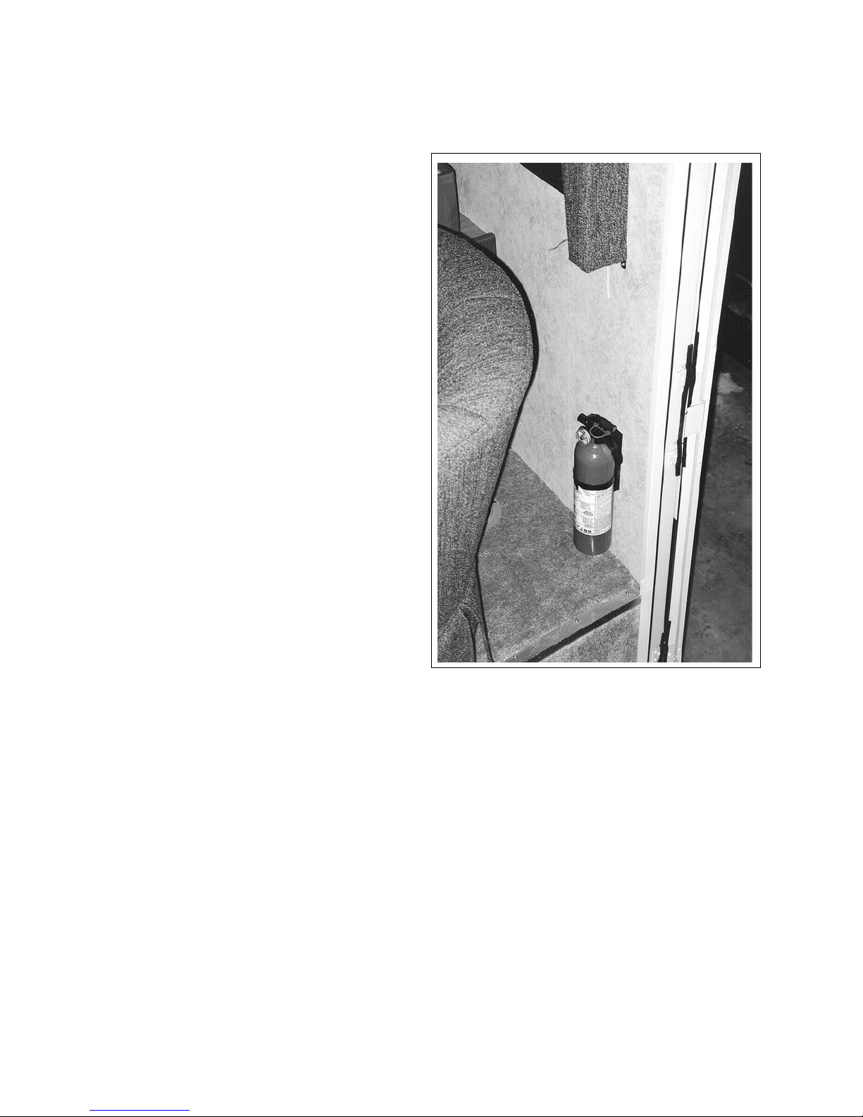
COMMANDER / EMBASSY
6.1.2 FIRE EXTINGUISHER
1. Function:
a. Fire extinguishers are designed to put
out a re in its initial stages. Once a
re is out of control and you cannot
get within ten feet, it is probably too
big to ght with your extinguisher.
b. Do not discharge your re extinguisher
to test it. Once it is discharged even
for a few seconds it will lose pressure
and become useless.
c. Check the pressure indicator on your
re extinguisher periodically and
record the inspection date on the tag
provided. It if loses pressure, the dry
chemical cannot be discharged eectively. If the pointer does not indicate
in the green, replace the extinguisher
immediately.
2. Operation:
a. Stay at least 6 feet away from the re
and near an exit. The chemical from
the re extinguisher will shoot at least
10 feet. Stay close to the oor to avoid
heat and fumes.
b. Break the seal; grasp the re extin-
guisher rmly holding it in an upright
position.
c. Press the white button. Aim at the
base of the re spraying the entire
base area. Don't spray at the smoke or
ames.
d. After the re is out, watch for “ash-
back”.
e. Discharge the re extinguisher entirely
and get it recharged or replaced immediately.
f. For additional information, check in
the manual that is provided with the
Fire Extinguisher.
Fig. 6-1 FIRE EXTINGUISHER
6-2
Page 57
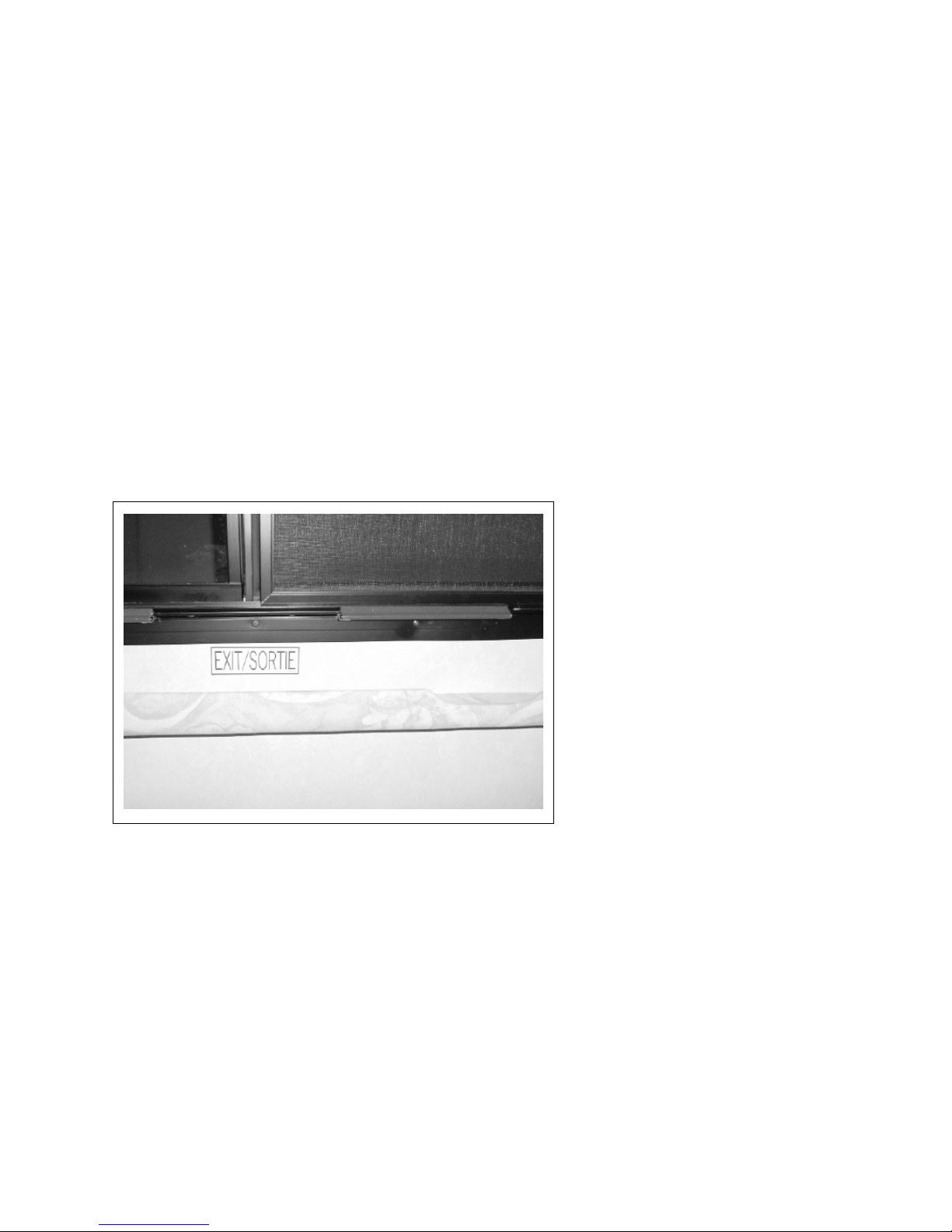
COMMANDER / EMBASSY
6.2 EMERGENCY ESCAPE
Each motorhome is designed with an alternate emergency exit via a window in the sleeping area.
1. Emergency Exit:
Release the red latches of the emergency egress window
and push out the window. (The egress window has hinges
on top).
2. Formulate a plan for escape from the vehicle should an
emergency arise. It is particularly important that the escape plan be rehearsed with everyone, especially children,
who will be travelling in or using the motorhome.
3. Do not release or open the emergency exits while the
vehicle is in motion.
Fig. 6-2 EMERGENCY EXIT LATCHES
6-3
Page 58
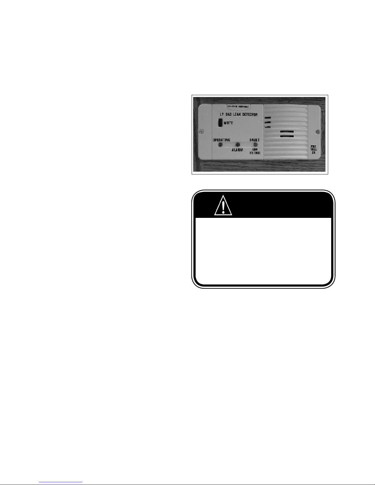
COMMANDER / EMBASSY
6.3 ALARMS
Each motorhome is equipped with an LP Gas, CO and smoke alarm as standard safety equipment. An intruder
alarm is available as optional equipment on some models. Refer to alarm manual(s) for more detailed instructions. Keep all alarms in good working order.
Recurring alarm(s) indicate the slow accumulation
of LP gas, carbon monoxide, or smoke. Have an
authorized service center check system and identify
source. Correct problem before resuming use of
unit.
6.3.1 LP GAS ALARM
This alarm is located in the lower portion of the
coach entry stairwell on Commanders and on the
interior lower cabinetry on Embassy's. It sounds
when there is an unsafe level of LP gas in the air.
a. When the alarm sounds, follow the instruc-
tions on safety sign next to stove and air
out vehicle to silence alarm.
b. Have a qualied service personnel nd the
leak and correct the problem before using
unit again.
c. Refer to section 11, LP Gas System and
alarm manual for more details.
IF YOU SMELL GAS
1. Extinguish any open ame, pilot lights and all smoking material.
2. Do not touch electrical switches.
3. Shut o thegas supply at the container valve(s) or gas supply connection.
4. Open doors and other ventilating openings.
5. Leave the area until the odour clears.
6. Have the gas system checked and leakage source corrected before
using again.
WARNING
6-4
Page 59
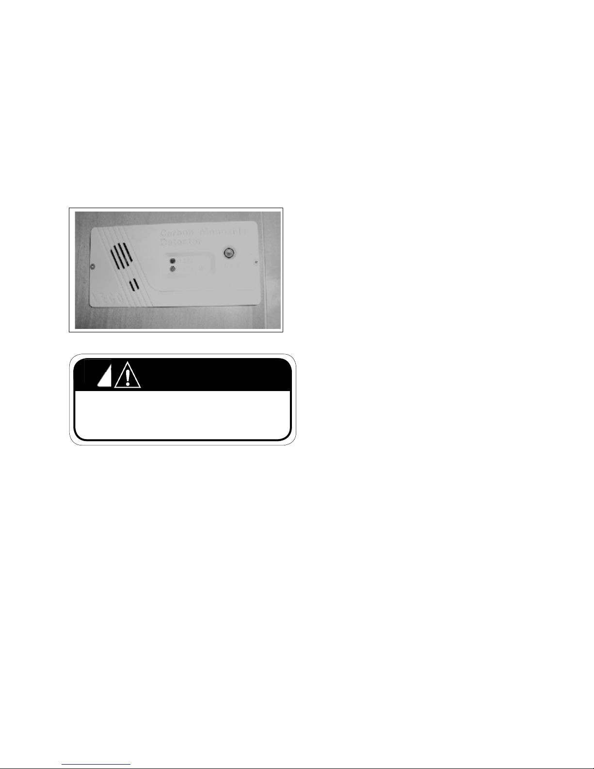
COMMANDER / EMBASSY
6.3.2 CARBON MONOXIDE ALARM
This alarm is located in the upper
cabinets in the living area and sounds
when there is an unsafe amount of
carbon monoxide in the vehicle.
Position motorhome so wind blows
exhaust fumes away from the coach.
Fig. 6-4 CARBON MONOXIDE MONITOR
WARNING
Carbon Monoxide gas is a odorless and colorless gas that
is lethal to people. Do not breathe any exhaust, heating
or cooking fumes to prevent asphyxiation.
When the alarm sounds:
a. Turn o all fuel burning devices.
b. Open doors, vents and windows to air out
vehicle and silence alarm. Leave the vehicle
until the alarm stops.
c. Have a qualied service personnel check all
appliances, etc.. Clean, repair or replace any
defective components.
d. Have a qualied service personnel check all
engine exhaust system components. Repair
or replace any defective components.
6-5
Page 60

COMMANDER / EMBASSY
6.3.3 SMOKE ALARM
This alarm is located in the coach and sounds whenever there is smoke in the unit. Always use the
exhaust fan, over the stove when cooking. Smoke
from cooking may trigger the alarm.
a. If alarm sounds, check for the presence of
a re. If re is suspected, leave the vehicle
immediately.
b. Open doors, vents and windows to air out
vehicle and silence alarm. Correct and
eliminate smoke source.
c. Check alarm on a regular basis. Check
when removing from storage, before trips
and weekly thereafter. Depress center
button to test alarm electronics. Test alarm
sensor by blowing smoke (from safe, refree source) past sensor. If alarm does not
sound when testing, determine source of
problem and correct or replace alarm.
Fig. 6-5 SMOKE ALARM
d. Do not remove battery to silence alarm.
When alarm “beeps” every minute, battery
is weak and must be replaced. Do not allow
battery to go dead. Be sure to replace with
recommended battery. Test after battery is
replaced.
e. Clean and vacuum opening on smoke alarm
once a month.
f. Do not try to repair alarm. Replace it.
g. Smoke alarms are not perfect and do not
respond in all situations. The best safe-guard
is re prevention.
6-6
Page 61
COMMANDER / EMBASSY
6.4 REAR VIEW CAMERA/MONITOR
SYSTEM
A rear view monitor camera is mounted on the back of
the unit to provide a view behind the unit.
1. Camera:
The camera is mounted to pick-up a view of the
area behind the unit for backing up or a trailer
that is being towed.
2. Monitor:
The monitor is mounted so it is visible to the
driver to assist in backing up or driving.
3. Operating Modes:
a. On/O:
In this mode, the system operates only when
the system is turned on. It is not recommended that it be operated on a full time basis
when driving as it can be very distracting.
b. Standby:
In this mode, the system automatically comes
on when the transmission is shifted into re-
verse to assist in backing up. It goes o when
the transmission is shifted back into drive.
Fig. 6-7 CAMERA LOCATION
4. Refer to the camera/monitor system manual for
more detailed operating and system instructions.
Fig. 6-8 MONITOR (TYPICAL)
6-7
Page 62
COMMANDER / EMBASSY
7 TRAVELLING
The motorhome has been designed to provide the
driver and passengers maximum comfort and convenience while travelling safely from one place to another.
It is the responsibility of the owner/operator/driver to
review the safety section at the front of this manual
and the chassis manual before travelling in the motorhome.
7.1 PREPARATION
Review the chassis manual and previous sections of
this manual before starting or driving the vehicle.
7.2 BAGGAGE LOADING
Your motorhome is equipped with exterior compartments for carrying or storing baggage or luggage. Do not
exceed baggage area loading or weight capacity and do
not exceed vehicle GVWR. Always secure your cargo and
keep the compartment locked when traveling.
7.3 VEHICLE WEIGHT LOADED
The loaded weight of the vehicle including passengers,
optional equipment, water, fuel, luggage and all other
cargo must not exceed the GVWR or GAWR indicated on
the Vehicle Certication Label.
7.4
FRONT AXLE TIRE ALIGNMENT
The front-end tire/wheel alignment was done at the
factory prior to delivery based on the vehicle being empty
and on the weight distribution at that time.
It is recommended that the front end be aligned once
you have established a loading pattern according to your
needs. After an initial adjustment, it is a good idea to have
the front suspension checked periodically and to check
tires regularly for abnormal wear.
7.5 MAXIMUM OCCUPANCY
The belted seating positions in your motorhome may be
dierent than the stated sleeping capacity. In the US this
is referred to as the Net Carrying Capacity (NCC) or the
Cargo Carrying Capacity (CCC) in Canada.
Triple E uses sleeping capacity as opposed to seating
capacity to determine the NCC or CCC. You may use all
the belted seating positions available in your motorhome
provided you stay within the GVWR listed on your Vehicle
Certication Label.
Fig. 7-1 BAGGAGE COMPARTMENTS
When loading the motorhome, make sure that the
Front or Rear Gross Axle Weight Rating (GAWR) or the
Gross Vehicle Weight Rating (GVWR) and the Gross
Combined Weight Rating (GCWR) are not exceeded.
Check your Vehicle Certication Label for weights. If
in doubt, take your motorhome to a weigh scale and
check the front axle, rear axle and total vehicle weight
on a scale.
Distribute the weight in the motorhome evenly from
side to side to maintain maximum vehicle stability.
IMPORTANT
It is recommended that all holding tanks be emptied
before travelling to avoid unnecessary weight.
CAUTION
WARNING
All occupants must be in seats equipped with lap or
shoulder harness seat belts and the seat belt fastened
before travelling. Small children should always be
placed in a certied child restraint system and secured
with a seat belt.
7-1
Page 63
COMMANDER / EMBASSY
7.6 SEAT BELTS
7.6.1 LAP BELTS
Seats intended for passenger use when travelling are
equipped with seat belts.
Make sure lap belts are adjusted to a snug t and as
low on the hips as possible for maximum safety and
protection.
WARNING
Snug and low belt position are important. In case of collision, the force will be spread over the strong hip area
rather than the weaker abdomen area. This could prevent
serious injury.
Only seats equipped with seat belts should be occupied
when travelling.
Fig. 7-3 LAP BELT (TYPICAL)
7.6.2 SHOULDER/LAP BELTS
The driver and co-pilot seats of your vehicle are
equipped with shoulder belts that have automatic
locking retractors that allow you to adjust the belt for
maximum comfort as well as safety.
Seat belts provide maximum safety only when adjusted and worn correctly when the seat is in the forward facing position. The lap part of the belt should
be worn as low as possible with the shoulder strap
diagonally across the chest, over the shoulder but not
against the neck.
NOTE
If you pull the strap away from the wall too
quickly, the automatic retractor may “lock”.
To free it, relax the tension and then pull it
away from the wall slowly.
CAUTION
Make sure all passengers are instructed on
the release mechanisms of the seat belts so
that they are able to get out quickly in case of
emergency.
Fig. 7-4 SHOULDER LAP BELTS
WARNING
Never wear seat belts in any way other than as
described. Serious injury may result from improper
use of seat belts.
7-2
Page 64
COMMANDER / EMBASSY
7.6.3 CARE AND CLEANING
1. Be careful not to damage the hardware or the
webbing of your seat belt. Take care not to pinch
them in the seat or doors.
2. Check belts and hardware from time to time.
Replace any damaged parts. Do not modify or
remove the belt system.
3. Keep belts clean and dry. If they need cleaning,
use a mild soap solution in warm water. Do not
use hot water, abrasives or bleach. These may
weaken the belts.
4. If you experience a severe impact, check for and
replace any damaged parts.
7.7 MIRRORS
Whether your vehicle is equipped with standard or
power electric mirrors, always check the adjustment
on your mirrors for maximum rear visibility before
driving.
The power electric mirrors ( Commander only) may be
adjusted using the multi-directional switch located
on your front panel. Select the right or left mirror
to be adjusted and then press the buttons until you
experience the best visibility. When you have adjusted
both mirrors for maximum visibility, place the selector
switch in the middle, neutral position to cut o the
power to the switch. This will prevent accidental misadjustment of mirror settings.
7.6.4 CHILD RESTRAINTS
In most jurisdictions across North America, child
restraint systems are a legal requirement. In order to
provide the best in safety measures for your child in
case of an accident, we make the following recommendations:
1. Purchase a certied child restraint system. Make
sure the system comforms to all Canadian and US
standards for safety requirements.
2. Make sure that the system will attach to your vehicle conveniently and provide safety for your child
every time it is used.
3. Be sure that the restraint system is suitable and
adequate for your child's age, weight and height.
Check the label for this information.
4. Ensure that the child restraint is installed per the
instructions provided with the restraint. If you are
unsure please contact the restraint manufacturer.
The power switch adjustment is intended for ne correction in mirror settings. If you are unable to adjust
your mirrors, you may need a coarse adjustment. This
can be done by loosening the set screws at the ball
and socket of your mirror (see Fig. 7-5). Adjust to the
proper settings and then tighten the screws. After this,
ne adjustment should be possible.
Your mirrors may also be equipped with defogging or
de-icing elements. The ON-OFF switch for the heater
mirrors is located near the remote mirror controls.
Set screw location
Fig. 7-5 MIRRORS
7-3
Page 65
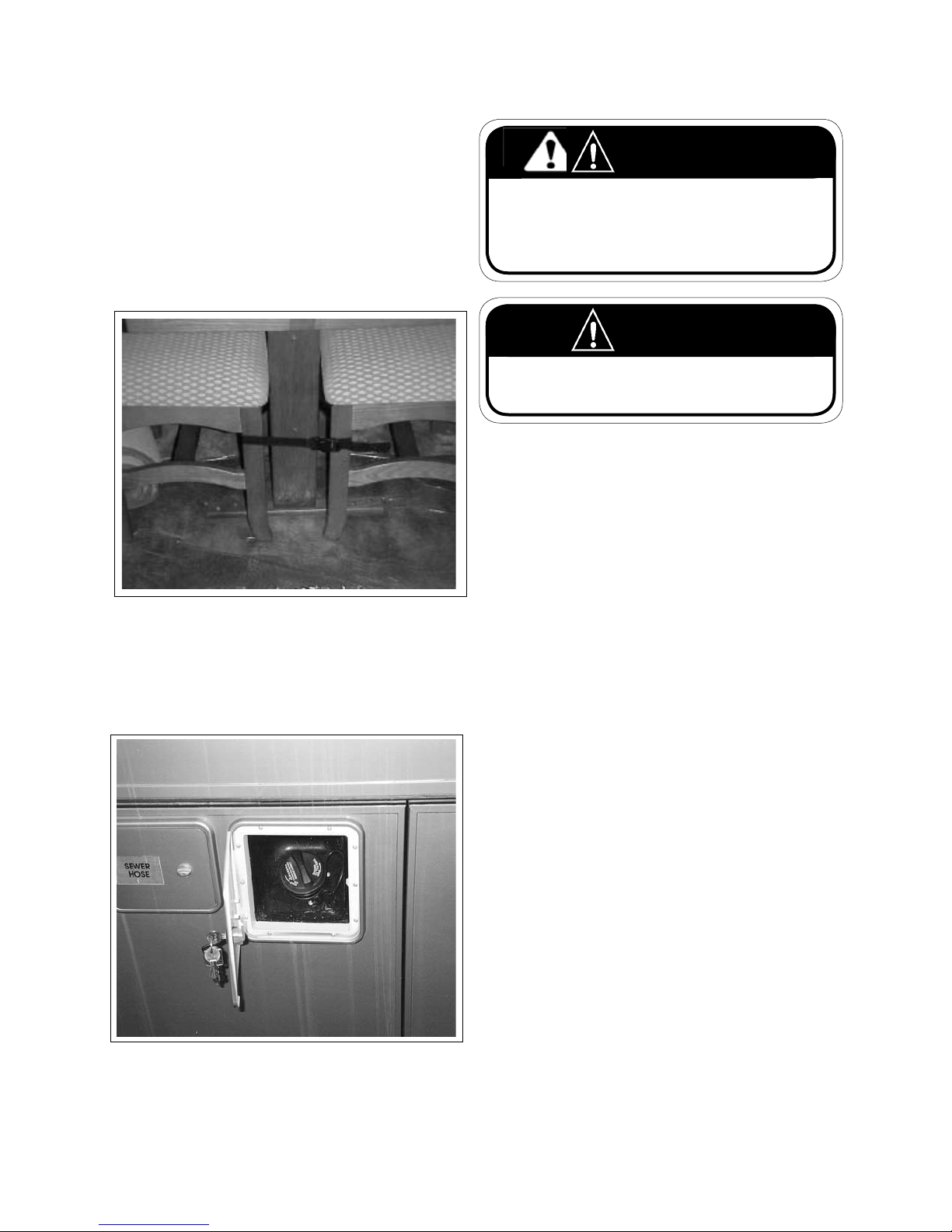
COMMANDER / EMBASSY
7.8 FREE STANDING TABLE & CHAIRS
(Optional)
Your motorhome may be equipped with a free standing dinette. While travelling, these should always be
secured with the harness provided to prevent the table and chairs from moving forward in case of sudden
braking or a collision and to keep them from sliding
around on the oor causing damage to the ooring.
Fig. 7-6 CHAIR HARNESS
7.9 REFUELLING
Consult your chassis manual for the type of fuel to use.
WARNING
Modern fuel systems may cause pressure to build up in
the fuel tank during hot weather. It may happen under
certain conditions, that a bit of fuel may spray from the
spout when the fuel cap is removed suddenly, causing a
possible hazard.
WARNING
Do not smoke when refuelling. Keep ames, sparks and
smoking material away from fuel or ammable fumes.
1. Removing The Fuel Cap:
Extinguish all pilot lights.
Rotate the fuel cap slowly and only far enough for
the pressure to be released i.e. until any “hissing”
sound stops. Then remove the cap.
2. Filling The Tank:
Fill only until the automatic shut-o valve cuts out.
This allows for expansion of the fuel and vapor
space as the fuel warms up in your fuel tank.
CAUTION
Overlling the fuel tank may cause damage to the
fuel evaporative emission system.
3. Fuel Tank Capacity: Check in the Chassis Manual for
capacities.
Fig. 7-7 FUEL CAP
4. Fuel Type:
Use only gasoline with this vehicle. The generator
uses fuel from main tank but the fuel pick-up line
is shorter than the engine pick-up tube, to prevent
the vehicle fuel tank from being completely emptied while on site.
7-4
Page 66

COMMANDER / EMBASSY
8 EMERGENCIES WHILE DRIVING
Your Triple E Motorhome is designed with features
that allow the driver/occupants to resolve emergency
or failures when travelling. Review this section to be
familiar with the recommended procedure to resolve
these conditions or situations. Review this section with
all new drivers and before each trip.
8.1 HAZARD WARNING LIGHTS
Each motorhome is designed with a hazard warning
light system that is similar to the system on an automobile. Both the front and rear turn signals ash in
unison when the system is turned on.
Although the control switch is normally located on
the steering column, refer to the chassis manual for
details.
It is recommended that the warning lights be used
whenever the vehicle is stopped on the side of the
roadway. The intermittent ashing lights will alert other
motorists to a potential hazard and to take extra care.
The system is designed to continue to ash when the
switch is on even though the ignition key is removed
and you have left the vehicle.
8.2 FLAT TIRE
When you have a at tire while driving, slow the vehicle gradually to prevent losing control and pull o to
the side of the road. Stop on a level rm surface and
engage parking brake. Turn on hazard warning lights
to alert other drivers to use extra caution when driving
in the vicinity.
It is recommended that a professional qualied road
service be used whenever possible. If this is not possible, follow the instructions in the chassis manual.
Refer to chassis manual for instructions on where to
place jack under the frame. Review and follow all
safety precuations listed.
Be sure the lug nuts are tightened to their specied
torque. Always use an accurate torque wrench when
mounting the wheel. Check the torque and re-tighten
after 25 and 100 driving miles. Check the wheel nut
torque at each oil change.
Safety Reminders:
1. Park the motorhome on a level surface.
2. Turn o the engine and set the parking brake.
3. Turn on the hazard warning asher.
4. Block both front and back of the tire on the opposite
side of the vehicle from the at tire.
5. If the ground is soft, use a support board under the
jack to keep the jack from sinking.
6. Make sure to use only the jacking points described
in your chassis owner's manual.
7. Never get any part of your body under the vehicle
while jacking or while it is suspended.
8-1
Page 67
COMMANDER / EMBASSY
8.3 TOWING
1. Emergency Starting:
Do not tow the motorhome in an attempt to start it.
The powertrain is not designed to transmit torque
to turn the engine over for starting.
a. Battery Booster Switch:
If the chassis battery does not have sucient
charge to start the engine, depress and hold
the battery boost switch to route the coach batteries energy into the circuit to start the engine.
Release the switch when the engine starts.
b. Jump Starting:
Refer to Section 8.5 “Jump Starting”.
2. Vehicle Break-Down:
When the vehicle breaks down, it should be towed
in for repair by an approved towing service. If the
vehicle breaks down on the roadway, pull o the
road and stop. Engage parking brakes and turn
on the hazard warning lights. Place chocks by the
wheels if it is not level.
Call an approved towing service to come and get
the motorhome. Be sure to tell the towing service
what kind of vehicle it is and its weight, length,
width and height. The towing company will then
dispatch a proper sized tow truck for your vehicle.
8.4 OVERHEATING
If the engine overheats while driving:
1. Pull o the side of the road and stop immediately.
2. Shut engine o.
3. Check for proper coolant level in the recovery tank.
The coolant level should be between the “full” and
“add” marks on the tank.
4. If the coolant level is low:
a. Check for leaks at hose connections, through-
out the cooling system. Make sure the belts are
tight and that the cooling fan is turning.
b. Add coolant to the recovery tank as soon as
possible.
c. If coolant is being lost due to leaks; if the fan belt
is broken or too loose; if the red warning light
stays on, stop the engine until the problem is
corrected.
5. Check the radiator face for obstructions such as a
build up of bugs. Have a professional service shop
clean your radiator if obstructed.
6. Once the temperature gauge returns to normal,
resume driving, keeping an eye on the gauge. Do
Not resume driving until the problem has been corrected and the temperature is normal.
WARNING
The drive shaft must be removed before towing. Failure
to do so will result in damage to the transmission.
WARNING
Never remove the radiator cap when the engine is hot.
Hot uid and steam can blow out and cause severe
burns.
8-2
Page 68
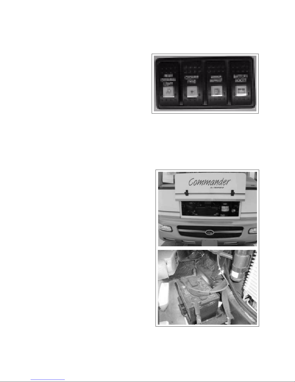
COMMANDER / EMBASSY
8.5 JUMP STARTING
When the vehicle batteries do not have sucient
charge to start the engine, there are two ways to start
the unit:
1. Battery Boost Switch:
Depress and hold the switch on the left side of
the dash to connect the coach batteries into the
starter circuit to use all batteries for starting. Release the switch when the engine starts. This will
disconnect the battery from the circuit.
1
2. Jump Starting:
Open the electrical utility compartment and
connect the jumper cables to the battery posts.
Always connect positive to positive. The negative
should be connected from the negative terminal
of the battery on the vehicle providing the boost
to the chassis of the vehicle needing the boost.
NOTE
See section 10.3.4 for battery mainte-
nance information.
Fig. 8-2 STARTING SWITCH
Fig. 8-3 CHASSIS BATTERY
8-3
Page 69
COMMANDER / EMBASSY
9 HOME USE
The motorhome is designed to be your home on
wheels while traveling in comfort. This section will
cover the items that must be done or considered in
order to obtain the maximum satisfaction from your
unit.
9.1 PARKING
1. Parking:
The motorhome can be stopped and parked just
like an automobile. However always remember
that the unit is longer, wider and higher than a car
and more room and clearance must be provided.
2. Backing Up:
a. Mirrors:
Large mirrors are mounted on both sides
of the cab to provide rearward visibility for
the drivers. However, they do not provide
visibility directly behind or on top (clearance)
of the unit.
b. Rear Camera:
An optional rear camera/monitor can be
mounted to your motorhome but it only
provides visibility directly behind the vehicle
(refer to Section 6.).
c. Spotters:
The best results are obtained when another
person helps guide the driver in backing the
unit into position. The driver and spotter
should agree to the meaning of hand signals
before starting the backing process. The
spotter should always be in a position that is
visible to the driver while backing.
3. Always set the parking brake and place chocks in
front of and behind the wheels to prevent the unit
from rolling.
9.2 MOTORHOME LEVELLING
SYSTEM (OPTIONAL)
The Motorhome must be level for some appliances to
function properly.
Your motorhome may be equipped with the optional
Hydraulic Levelling System which is designed to make
“set up” a lot easier, safer and more convenient.
IMPORTANT
Fig. 9-1 LEVELLING SYSTEM CONTROLS
When parking your motorhome on a uneven site,
always park with the front of your motorhome facing
downhill. This allows you to raise the front of your
motorhome in order to level it. When you place your
transmission lever in PARK, this locks only the rear
wheels. If you raise the rear wheels with your levelling
system your vehicle could roll o the jacks or cause
undue pressure on the jacks.
WARNING
Keep all people clear of the motorhome while operating
the Levelling System.
Do not use the Levelling System to support the vehicle
When using the levelling system:
1. Extending Levelling System:
a. Shift transmission to the PARK position and set
b. Turn the system on by pressing the ON button
c. Operate the joy stick controls to level the
d. Check that all jacks are down. Place pads un-
for tire changing or service.
the park brake rmly. Turn the ignition switch
to the ACC position.
on the HWH hydraulic leveling keypad. The
indicator light will glow.
motorhome.
der each jack if ground conditions require it.
9-1
Page 70
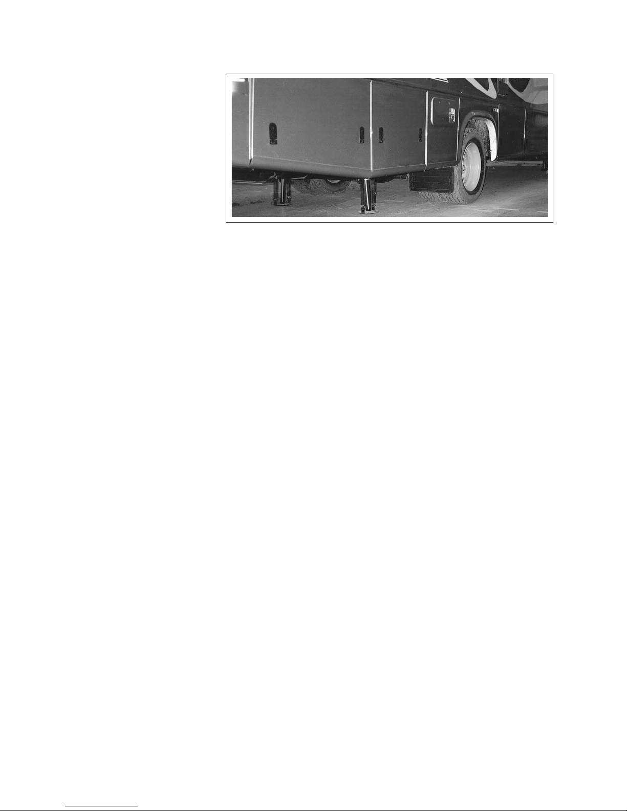
COMMANDER / EMBASSY
e. A yellow light indicates
that the end or the side
of the motorhome is
low. Move the Control
Lever to raise the cor-
responding end or side
until all the lights are
out. If the ground is too
uneven, there may not
be enough stroke in the
jack to raise that side
or end suciently. In
that case you may have
to move to a dierent
spot.
f. Once your motorhome is level, any jacks not
extended may be lowered to the ground to
provide additional stability against winds or
movement in the motorhome.
g. Press the OFF button and turn the ignition o.
2. Retracting Levelling System:
a. Remove all objects from underneath the
motorhome and make sure everyone stands
clear.
b. Move the Jack Levers to the storage/travel
position. The jacks will retract.
c. Check all warning lights. They should all be
o.
d. Check underneath your motorhome to make
sure all jacks are in the travel position.
e. If the system fails and the jacks do not retract
as described, check for Troubleshooting Tips in
the Operator's Manual for the system.
f. It is now safe to travel.
Fig. 9-2 JACKS EXTENDED
CAUTION
Do not rely only on the warning lights to indicate the
position of the jack levers. Make sure they are in the up
position before moving the vehicle.
For more information on your Hydraulic Levelling
System, check your Operator's Manual in the Owner's
Information Package. it contains more detailed
instructions, precautions and technical information.
9-2
Page 71
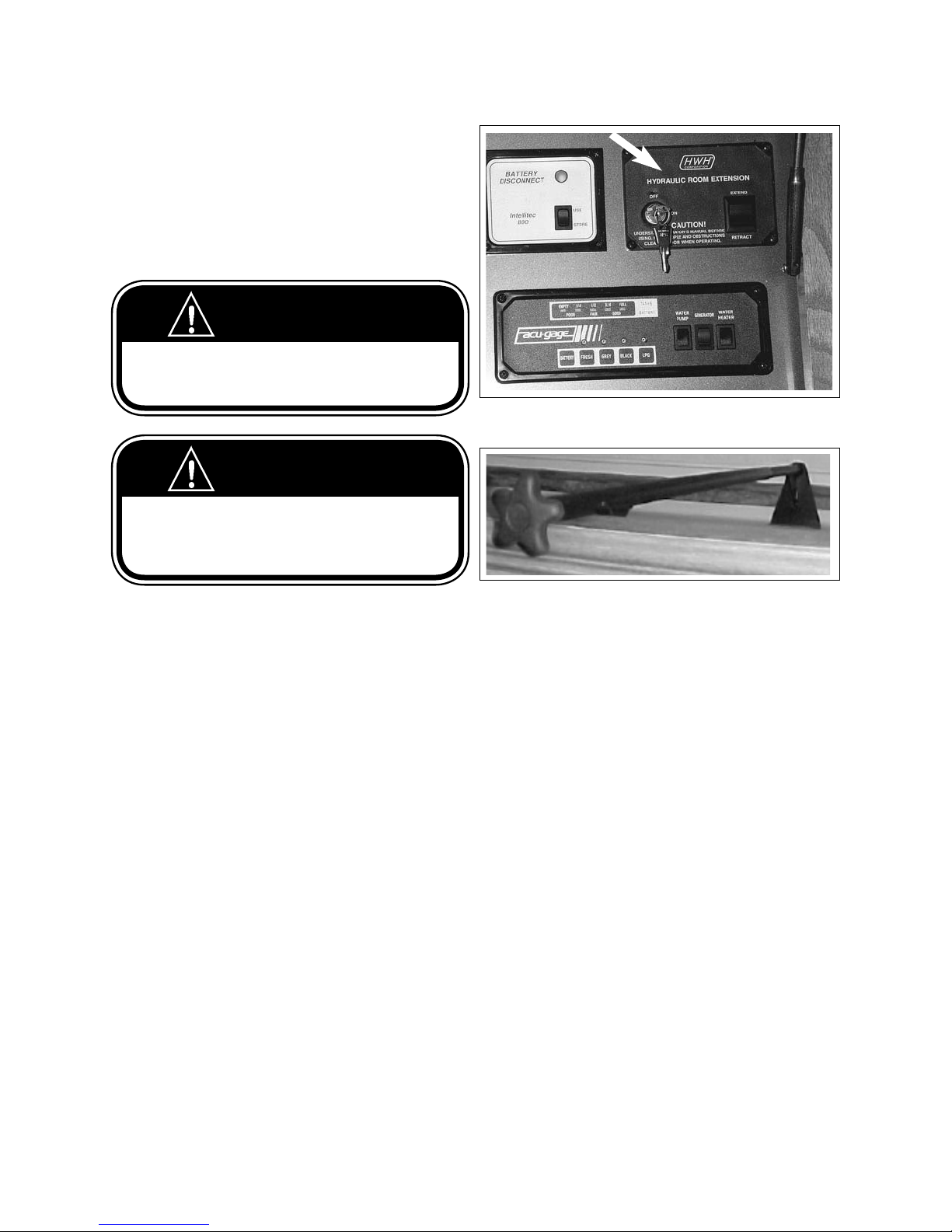
COMMANDER / EMBASSY
9.3 SLIDE OUT ROOM
A motorhome may be equipped with one or more
expandable slide out room(s) to provide more living
area for the occupants. Triple E supplies a video
explaining the operation of the slide out system with
each slide out equipped model. Please use this video
to familiarize yourself with the operations of this
system.
WARNING
Make very sure that everyone is standing clear of the
interior and exterior path of the slide-out as you extend
and retract it.
WARNING
Make sure travel locks are removed before extending
the slide-out.
Make sure travel locks are fastened securely before
moving the motorhome.
Fig. 9-3 CONTROL PANEL
9.3.1 SLIDE OUT ROOM OPERATION
Follow this procedure when using slide out room:
1. Be sure that motorhome is properly levelled
before opening the slide-out room(s).
IMPORTANT
If the unit is not properly levelled before extending
the room, the slide out mechanism may bind and be
damaged. The levelling jacks must be down and the
lights on the jack control panel on in order for the
slide out control to operate.
2. Before operating slide out:
a. If this is the rst time you are operating the
slide-out, take time to view the video on
Operating the Slide-Out that you received
from your dealer at the time of delivery.
b. Level the motorhome following the instructions
in Levelling Your Motorhome.
c. Make sure there is adequate space beside
your motorhome for the slide-out room to be
extended.
d. Remove the two travel locks located at oor
level on a galley slide unit or above the slideout on all other slide models.
e. Check the interior of the slide-out to make
sure there are no obstructions on the oor
Fig. 9-4 TRAVEL LOCKS
or leaning against the walls. Close all cabinet
doors.
f. Check the exterior of the unit to ensure all
baggage doors are closed and all obstructions
are removed.
g. M ake sure all people stand clear before
operating the slide-out room controls.
IMPORTANT
The hydraulics that operate the Main and Galley
slide-out are run by a 12-volt pump. When
operating the slide-out, make sure your batteries
are fully charged or you are hooked up to 120 volt
power. You may also choose to use the Generator
(optional) on your motorhome.
CAUTION
If your Motorhome is equipped with more than one
slide-out, Do Not operate both at once. This could
overload the electrical circuit and cause it to trip.
9-3
Page 72
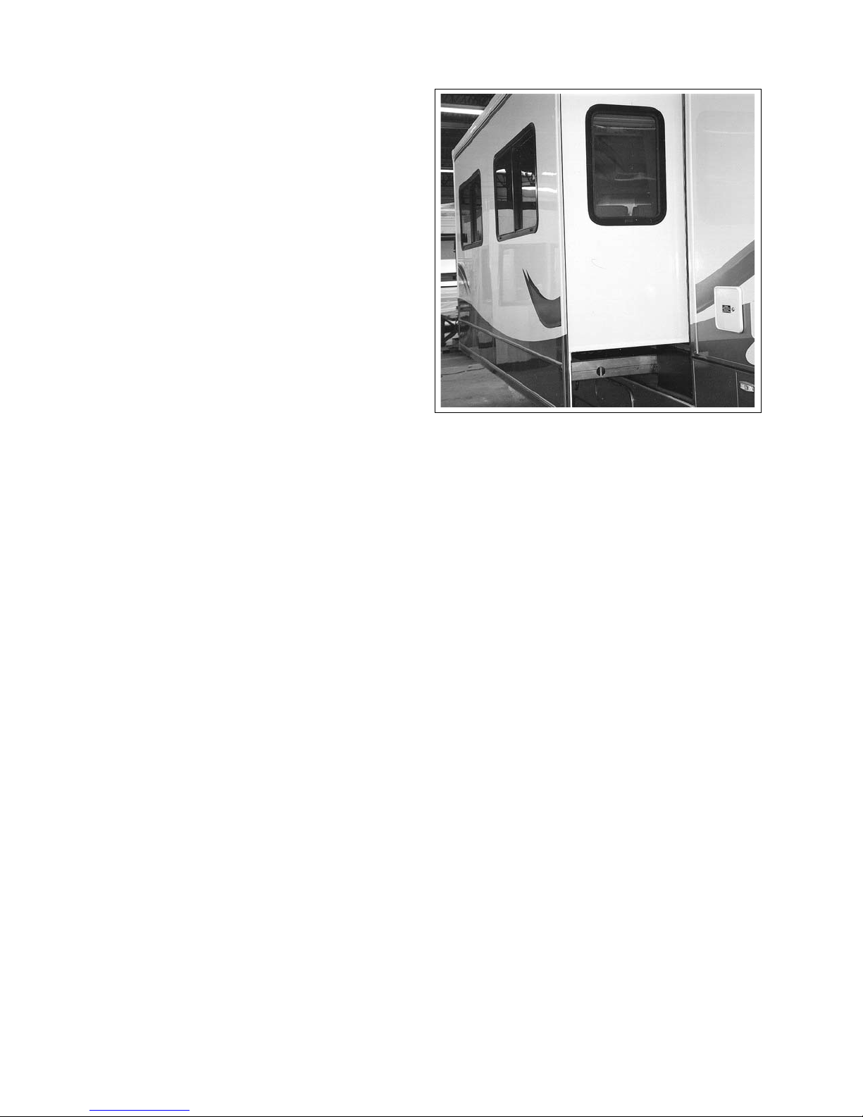
COMMANDER / EMBASSY
3. To Extend (Main & Galley Slide):
Turn the power lock key to “on’, press and hold
the control switch located above the entrance
door until it is fully extended. Make sure it is fully
extended so that all weather seals will be in their
proper alignment.
4. To Retract (Main & Galley Slide):
Be sure that there are no obstructions inside or
outside the motorhome that would prevent easy
operation. Turn ignition to accessory position
and turn the jack control panel on. Press and
hold the control switch on the slide out control
until the room is back in place. Install the travel
locks and prepare the rest of the motorhome for
travel. Turn key switch on the slide out control to
the "o" position and remove the key.
5. To Extend (Bed & Wardrobe Slide):
Press and hold the control switch located on the
bedroom or hall wall until it is fully extended.
Make sure it is fully extended so that all weather
seals will be in their proper alignment.
6. To Retract (Bed & Wardrobe Slide):
Besure that there are no obstructions inside or
outside the motorhome that would prevent easy
operation. Press and hold the control switch until
it is fully retracted. Install the travel locks.
CAUTION
Never move your motorhome with the slide-out
extended. Severe damage could result. Before
moving the motorhome, the slide-out must be
securely retracted and all travel locks fastened.
7. Set-Up:
Service by a professional, adjustments, regular
maintenance and replacement of weather seals
Fig. 9-5 ROOM EXTENDED
as needed will extend the life and comfort of your
slide-out unit.
8. Seals:
Cracked and worn weather seals may allow
moisture and dirt to enter your motorhome and
cause premature deterioration of the interior.
Check the seals carefully in fall and in spring and
have them replaced if necessary.
Extensive travel and use in severe weather
conditions may cause a more rapid deterioration
of some components, especially weather seals. In
some extreme circumstances these may need to be
replaced.
9-4
Page 73
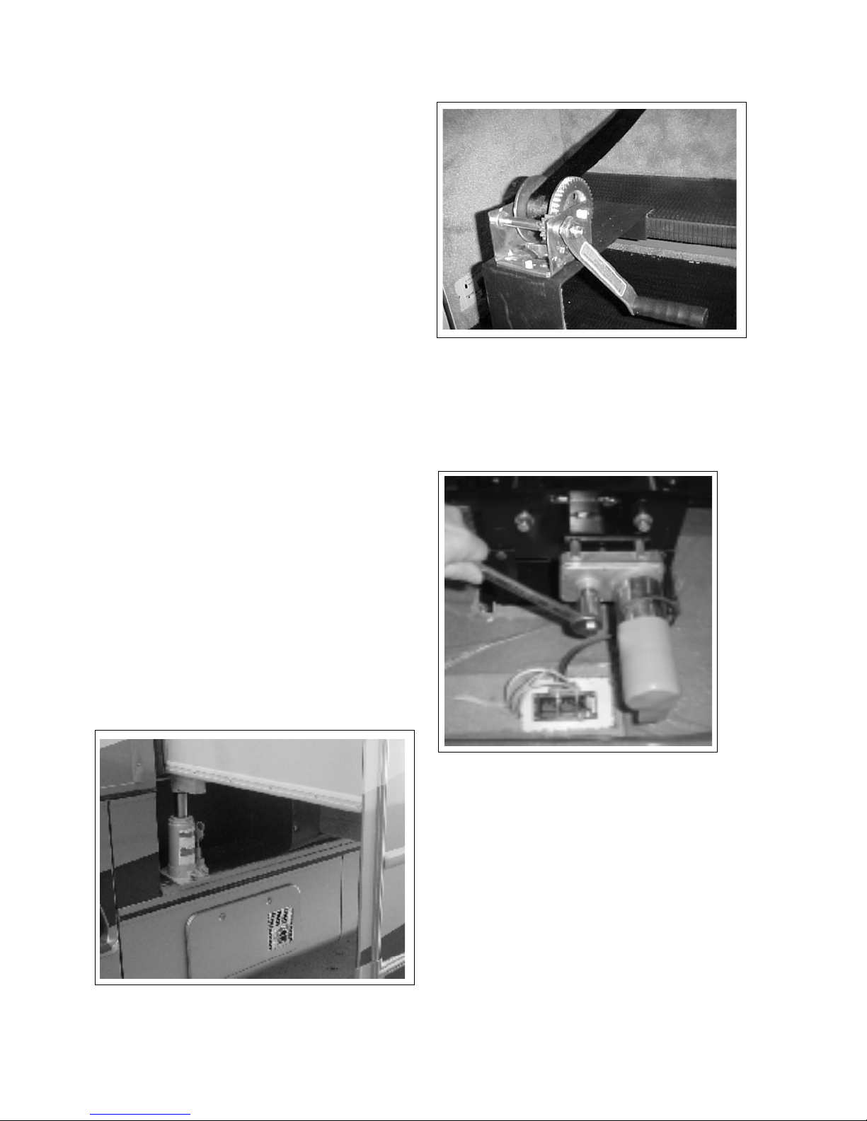
COMMANDER / EMBASSY
9.3.2 SLIDE-OUT ROOM EMERGENCY
OPERATION
1. Main Slide
The slide out room can be manually retracted in
case of system failure.
Before starting to manually retract the Slide-out
room check the battery voltage. If the voltage is
low have the batteries recharged and try again.
Before manually retracting the slide-out room
check to see if there are any obstructions. See the
Owners's information package for information how
to release the hydraulic system pressure. Attach
the winch to the entrance door step or the cocktail
chair pedestal (depending on the model) and then
hook the strap to the couch seat belt or special
bracket attached to the base of the couch. Turn the
winch crank to apply pressure to the room.
Fig. 9-7 WINCH ANCHORS
Operator's manual in the Owner's Information
package for further information.
CAUTION
Maintain a rm grip on the winch handle at all
times. Never release the handle when rachet lever
is in the o position and the winch is loaded.
The winch handle could spin violently and cause
personal injury.
Lift up the room on both sides at the same time
(about 10 milimeters or half and inch at a time)
using two bottle jacks placed in the opening
underneath the slide-out room. Use a block of
wood to protect the slide-out oor from being
damaged by the jack. See Fig.9-6. Raise each jack
about 10 mm (half an inch) at a time Keep turning
the winch crank to move the room up and in.
Install travel locks.
Refer to the Triple E supplied video and the HWH
2. BEDROOM & WARDROBE SLIDE
The slide out room can be manually retracted in
2
1
Fig. 9-8 ELECTRIC MOTOR
case of system failure.
Before starting to manually retract the Slide-out
room check the battery voltage. If the voltage is low
have the batteries recharged and try again.
Before manually retracting the slide-out room check
to see if there are any obstructions.
Fig. 9-6 BOTTLE JACK LOCATION
Locate the electric motor under the bed or below
the oor. Push the power lock control lever '1'
sideways to disengage the motor. Apply a wrench
to the manual control tting '2' and turn it to bring
the slide-out room in. Install the travel locks.
9-5
Page 74
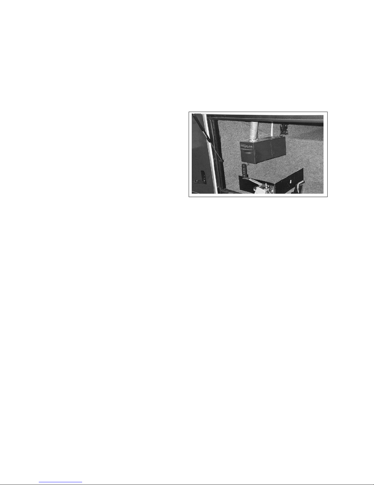
COMMANDER / EMBASSY
9.4 SLIDE OUT ROOM
TROUBLESHOOTING
1. Low Battery Voltage:
a. The most common cause of malfunction is low
battery voltage. To ensure adequate power,
take the following steps:
b. Run the motorhome engine while operating
the slide-out. This will ensure that the engine
alternator is delivering extra charge to the
batteries, or
c. Connect your shoreline to an external 120-volt
power source. This will activate the converter
and charge the batteries, or
d. Reduce the electrical load to a minimum by
shutting o all 12-volt lights and appliances.
2. Sticking or Binding:
a. If the motorhome is not levelled and stabilized
properly, the tracking system may bind. Make
sure the motorhome is level and stable. Level
the motorhome prior to extending the slide,
to ensure it works smoothly.
b. If the slide-out has been in one position
(retracted or extended) the seals may have
a tendancy to stick. DO NOT use petroleum
products on these seals as they can cause
premature seal deterioration.
9.5
CENTRAL VACUUM SYSTEM (ON
COMMANDER ONLY)
Your Motorhome may be equipped with an optional
central vacuum system eliminating the need for a
portable unit.
This unit operates on the 120 volt system requiring
that you be hooked up to shore power or run it o the
generator.
Check the system regularly to make sure the vacuum
bag is not full. Failure to do adequate maintenance will
Fig. 9-9 CENTRAL VACUUM
aect the performance of the vacuum. Check with the
System Manual in your Owner Information Package
for more detailed information and instructions on the
proper use and function of this system.
9.6 PROLONGED OCCUPANCY
Motorhomes are generally designed for recreational and
short-term occupancy. In case of extended occupancy
there are a few things to keep in mind regarding
humidity and condensation. Excessive moisture inside
the motorhome can cause water stains and mildew on
the upholstery, the wall materials and the woodwork.
Moisture condensing on the windows is a sure sign that
the humidity inside your motorhome is too high.
To reduce moisture inside your motorhome we suggest
the following:
1. Open windows and vents. This will allow fresh air to
ow through and reduce the moisture content.
2. Run the bathroom fan when using the bathroom
and turn on the range hood fan while cooking.
This will remove unnecessary moisture from your
motorhome. Do not hang wet towels and swim wear
inside the motorhome to dry.
9-6
Page 75
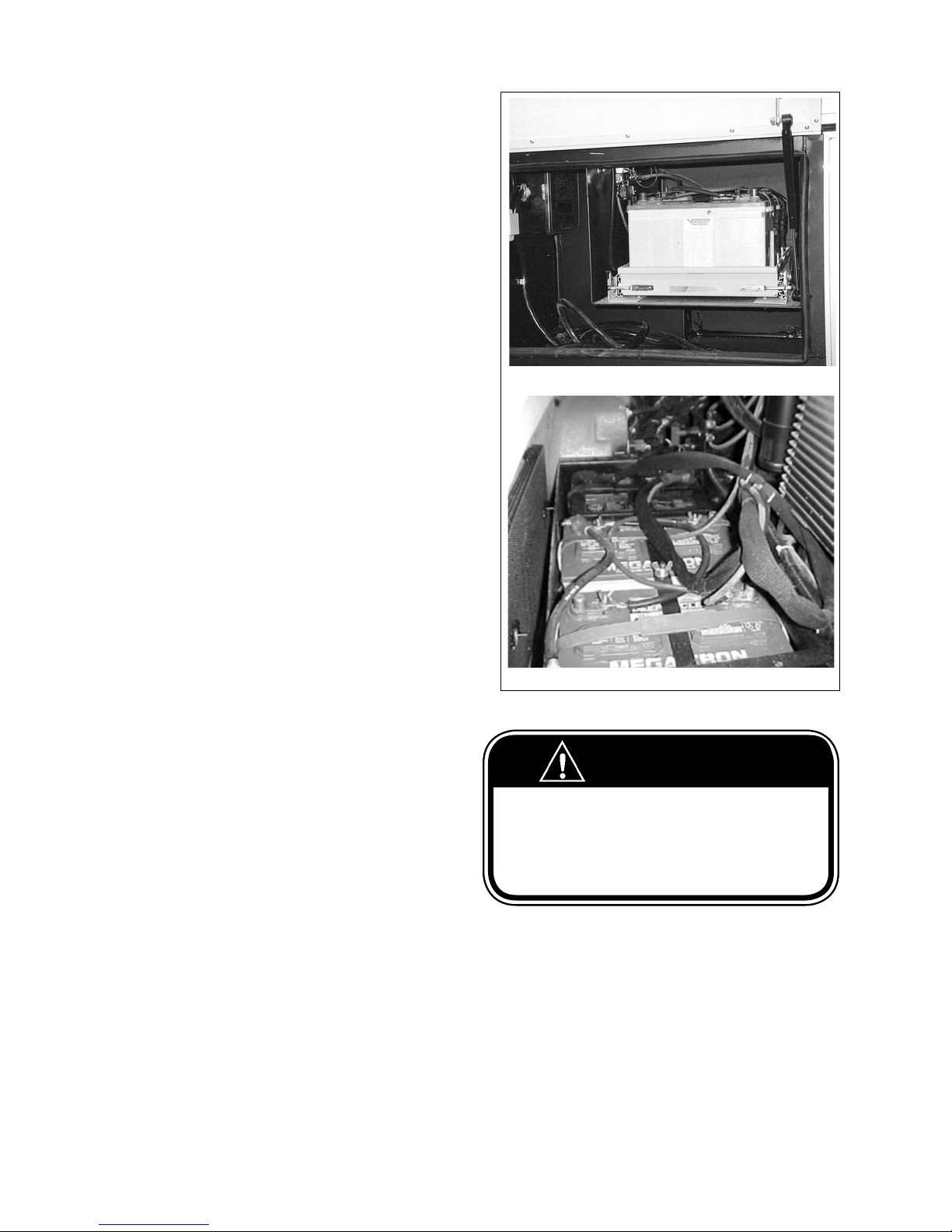
COMMANDER / EMBASSY
10 ELECTRICAL SYSTEMS
Your Motorhome is equipped with two electrical
systems operating on separate voltages - a 12 Volt DC
System and a 120 Volt AC System.
The Motorhome's 12 Volt DC System draws its power
from the coach batteries while the chassis batteries
remain dedicated to engine starting and powering
chassis loads. An isolator solenoid is installed and
controlled so that when the chassis batteries are being
charged by the alternator, and certain conditions are
met the coach batteries will also be charged. Likewise,
when the coach batteries are being charged by a
converter or inverter, the isolator solenoid system will
connect the coach and chassis batteries together so
the chassis batteries are also charged.
There is a 12-volt Coach battery fuse block in or near
the 120-volt circuit breaker panel where all coach
battery loads are fused. In addition to the chassis
provided fuse centers, your coach has a Triple E
provided 12-volt chassis battery fuse block locatee in
the dash area. Most Triple E added loads to the chassis
battery are fused at this location.
The 120 Volt AC System is powered either by the
optional generator installed in your Motorhome or by
Shore power plugged into the appropriatly sized and
congured shore power receptacle. Individual branch
circuits are fused in the breaker panel and in the case
of an inverter, two more branch circuit breakers are
located on the inverter.
Commander
10.1 120 VOLT AC SYSTEM
When connected to an outside electrical utility such as
that provided by most campgrounds or when running
your 120 volt generator, the converter supplies 12V
power and also charges coach batteries. All equipment
that normally is powered through the battery system
will now get its power from the converter.
Some equipment, however, depends entirely on 120
volts from an outside connection or from the optional
120 volt generator.
These include:
1. Roof Air Conditioners
2. Refrigerator (when set to 120 volt)
3. Microwave Oven
4. Ice Maker
5. Central Vacuum
6. All 120 Volt Electrical Outlets
7. Energy Management System
10.1.1 EXTERNAL POWER CORD
(SHORE POWER)
The external utility power cord (also called “Shore
Power”) is stored in the compartment on the left
Embassy
Fig. 10-1 COACH BATTERY LOCATION
WARNING
Do not connect the external power cord until you have
checked with the owner/attendant of the campground
as to proper polarity and grounding.
Improper grounding or reverse polarity can cause com-
ponent failure, serious injury or death.
(driver's) side of the motorhome.
To connect your motorhome to an external power
source, pull the cord through the cord hatch and plug
it into the proper receptacle. Always ensure some slack
is present in the cable.
10-1
Page 76
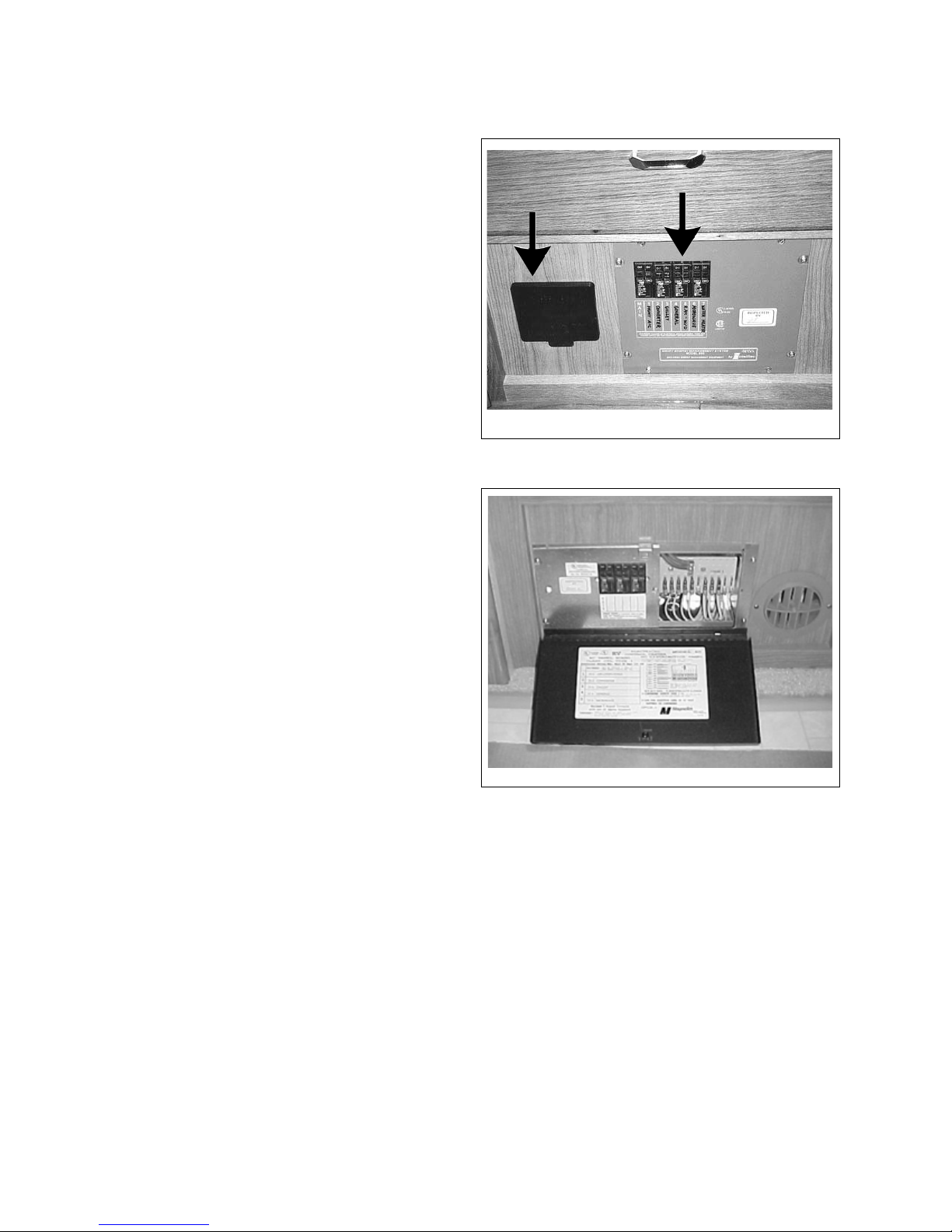
COMMANDER / EMBASSY
10.1.2 POWER CONTROL CENTER COMMANDER ONLY (OPTIONAL)
This panel contains the fuses for the 12 volt system,
circuit breakers for the 120 volt system. 120V power to
12V DC converter is mounted in compartment behind
the panel. Each system handles dierent circuits in the
motorhome.
10.1.3 120-VOLT CIRCUIT BREAKERS
The breaker panel protects all 120-volt equipment and
components in the motorhome from overload, from a
short in the wiring or a short in the component itself.
This cuts o the ow of electricity in the system and
prevents damage or re.
If a breaker “trips”, allow a brief “cool down” period
and then reset the breaker by turning it OFF and then
ON. If a breaker “trips” again, this could mean that
there is a short in the wiring or in the equipment and
both should be checked and serviced by a qualied
technician.
120V Breaker Panel
12V Fuse Panel
Commander
Fig. 10-2 POWER PANEL (OPEN DOORS)
There is a singular panel switch which protects the
entire electrical system. Become familiar with the
locations of the main 120v breaker and check it rst if
electrical problems should be experienced.
Refer to control panel manuals for more information.
Embassy
Fig. 10-3 120-VOLT CIRCUIT BREAKERS
ELECTRICAL PANEL SHOWN
10-2
Page 77
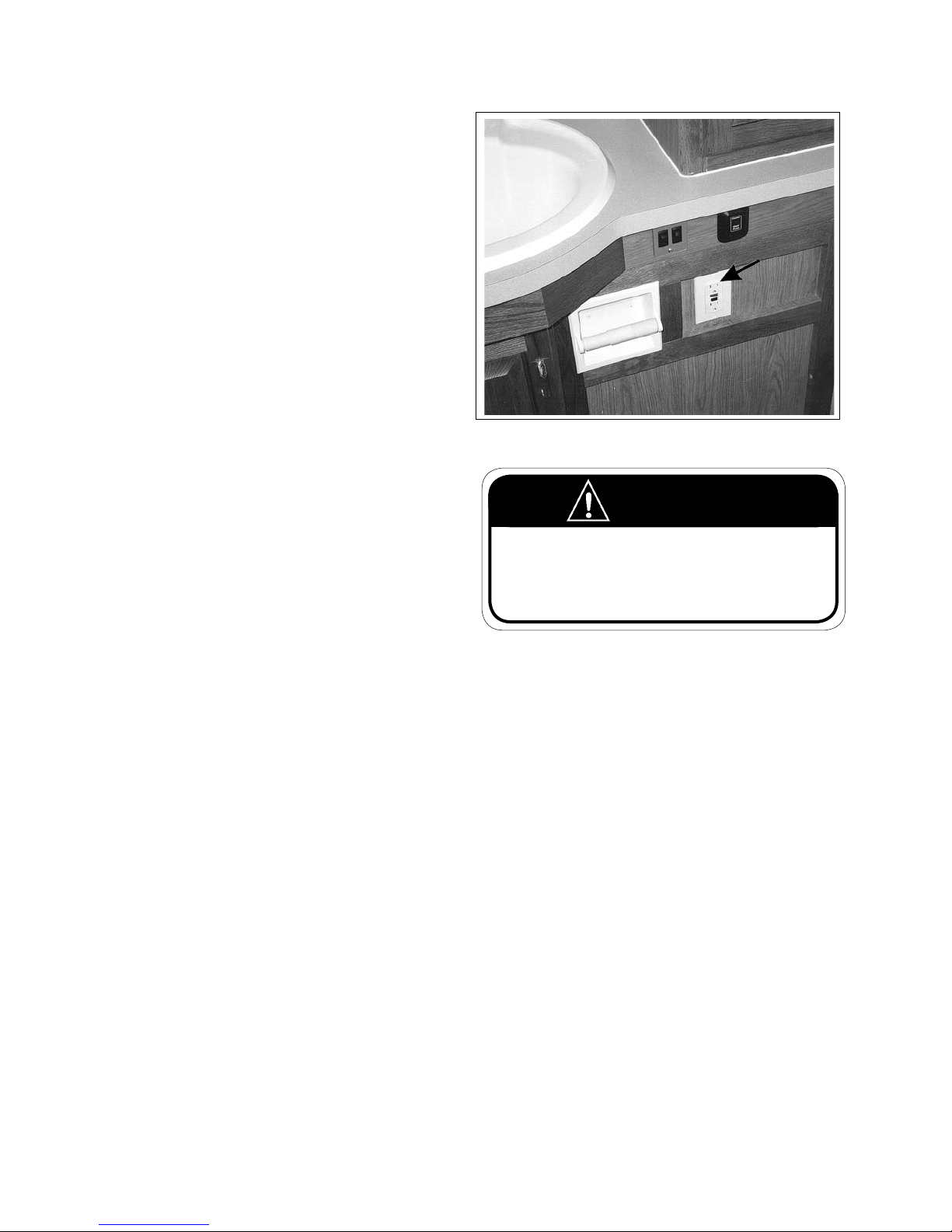
COMMANDER / EMBASSY
10.1.4 GROUND FAULT CIRCUIT
INTERRUPTER (GFCI)
Various outlets in the motorhome, particularly those
near sinks and water supplies, are connected to a
GFCI which is a very sensitive circuit breaker that will
protect you from electrical shock if a ground fault
develops. If and when this breaker trips, unplug all
appliances on that circuit and press the reset button
on the outlet.
If the GFCI keeps tripping have the problem investigated and repaired by a qualied technician before
using it again.
Depending on the oor plan in your vehicle, you will
nd a GFCI outlet in the bathroom and outside receptacle.
Please note that on some models the GFCI circuit in
the bathroom will trip when a fault occurs at an exterior plug. Both plugs are GFCI protected through the
bathroom circuit. If the exterior plug does not work,
check the bathroom GFCI receptacle.
Fig. 10-4 GFCI OUTLET (TYPICAL)
WARNING
The GFCI will not completely eliminate all elec-
tric shock. Small children or persons with a heart
condition should be extra cautious and could still
be injured even though protected by a Ground Fault
Interrupter.
10-3
Page 78
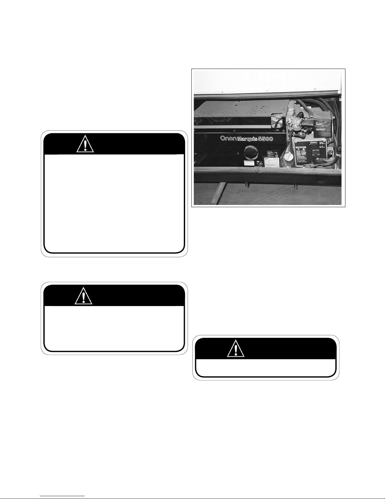
COMMANDER / EMBASSY
10.2 AUXILIARY 120 VOLT GENERATOR (OPTIONAL)
Refer to the Generator Owner Operator's Manual
for more detailed instructions.
10.2.1 GENERATOR SAFETY
1. Electrical:
WARNING
Extreme care and caution should be exercised when handling the generator and its components. Carelessness can
be dangerous and even fatal.
Never touch any electrical leads, equipment or appliances
when your hands are wet or when you are standing on
wet ground or in water.
Any repair of the generator should be done by authorized
service centers only. Never attempt to repair it yourself.
Plug in the power cord only when the generator is o.
2. Asphyxiation:
WARNING
All internal combustion engines produce carbon monoxide (CO) gas fumes when running. This gas is poisonous,
colorless, odorless, tasteless and lighter than air. These
gases can readily be drawn into your motorhome. Take
the following precautions when running any engines.
a. Do not run the generator and a ventilator fan
at the same time. This could draw gases into
the motorhome.
b. Do not open windows or ventilators on the
side where exhaust pipes are located.
Fig. 10-5 GENERATOR
c. Park so that winds will carry gases away from
the vehicle. Be aware of potential gas fumes
from other nearby vehicles.
d. Do not operate the generator if there is any
obstruction such as vegetation, snow, buildings, etc. which could deect gas fumes
under or into the motorhome.
IMPORTANT
Check the oil level regularly during frequent use of
the generator. Refer to the Manufacturer's Manual for
specic information.
WARNING
Never check generator oil level while generator engine is
running.
10-4
Page 79
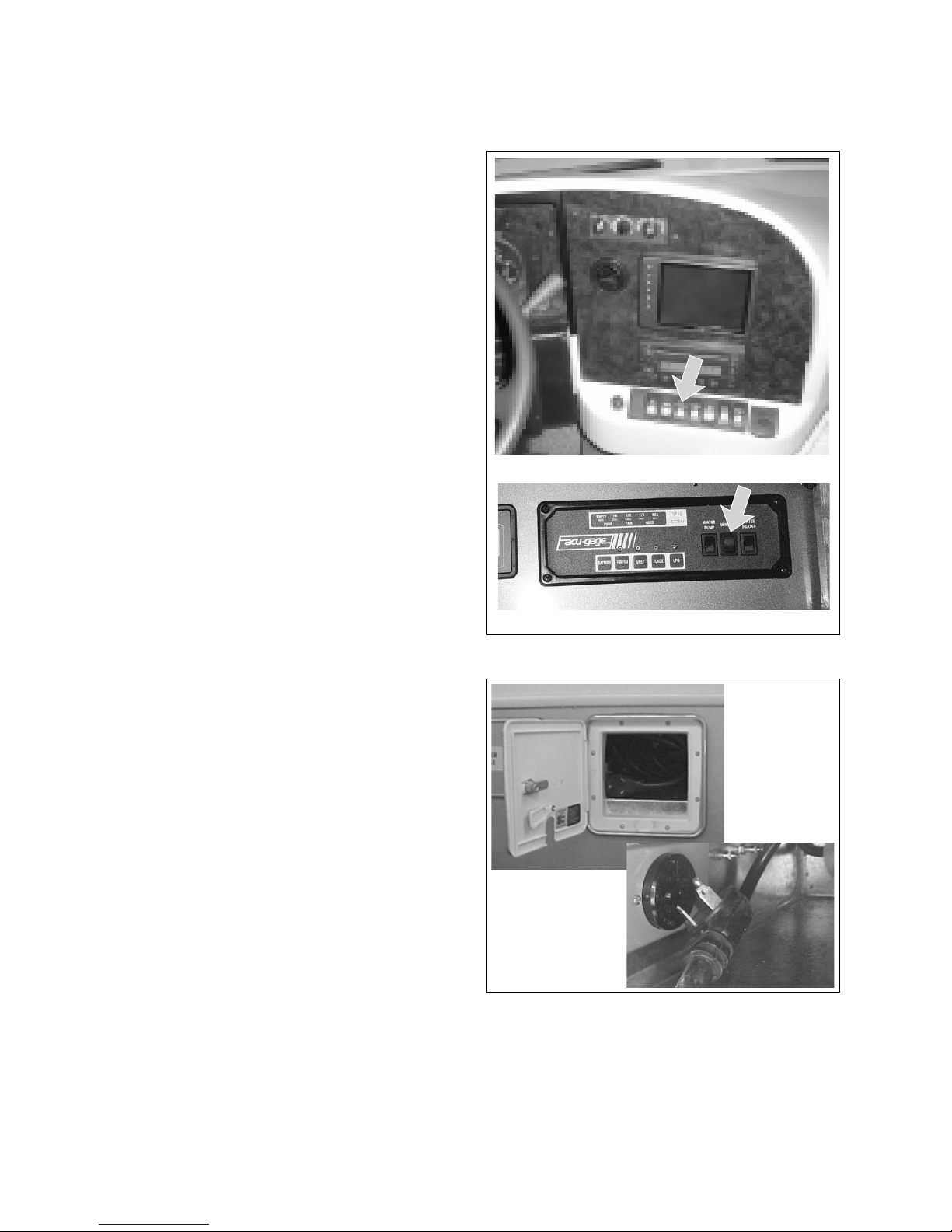
COMMANDER / EMBASSY
10.2.2 GENERATOR OPERATION
1. Controls:
The generator switches are located:
a. On the dash board, within easy reach from
the driver's seat.
b. Above the main entrance door, part of the
main control panel.
2. Starting:
a. The generator starter draws current from the
Coach batteries so the chassis ignition does
not have to be on.
b. See Generator Manufacturer's Manual for
specic instructions.
c. Disconnect all electrical loads. (Turn o all
lights, appliances, equipment, etc.).
d. Press generator start button, hold until
engine is running, then release.
e. Wait for engine to run smoothly before
turning on lights and appliances.
f. Be familiar with the output capacity and
capability of your generator.
g. Be careful not to overload the generator. See
your manual for information.
Dash Board (Commander)
CAUTION
Overloading the generator for long periods of time
can cause high temperatures that could result in
damage to the generator windings. Keep electrical
loads within the wattage ratings specied in your
manual.
3.Stopping:
a. Turn o lights and all appliances before
shutting o engine. Let the engine run at noload for a few minutes to allow the engine to
cool down.
b. Press the OFF switch and hold until engine
comes to a complete stop.
Entrance Door (Embassy)
Fig. 10-6 GENERATOR CONTROLS
Fig. 10-7 EMBASSY POWER CORD
10-5
Page 80
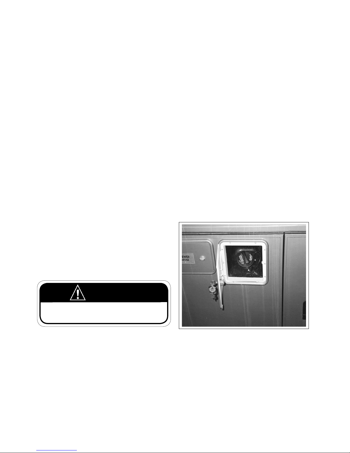
COMMANDER / EMBASSY
10.2.3 AUTOMATIC POWER TRANSFER SWITCH
(COMMANDER ONLY)
This Commander model is equipped with an automatic power transfer switch that transfers the electrical load between the shoreline or generator power
source. It automatically transfers all the load to shoreline whenever it is plugged in. The shoreline must be
unplugged to utilize power from the generator.
When the generator is started, the transfer unit bypasses all electrical loads for 30 to 45 seconds to allow
for easy starting. Then when the generator is running
smoothly, the electrical load is applied.
When the shoreline is plugged in to an outside power
source the transfer unit automatically switches away
from the generator to the shoreline. If you wish to use
the generator only, unplug the shoreline power cord.
10.2.4 GENERATOR REFUELLING
The generator fuel pick-up tube is located within the
main fuel tank. This fuel pick-up is shorter than the
engine pickup tube, to prevent the vehicle from being
without fuel while on site.
WARNING
Do not smoke when refuelling. Keep ames, sparks and
smoking material away from fuel or ammable fumes.
Fig. 10-8 GENERATOR REFUELING (GAS ONLY)
10-6
Page 81
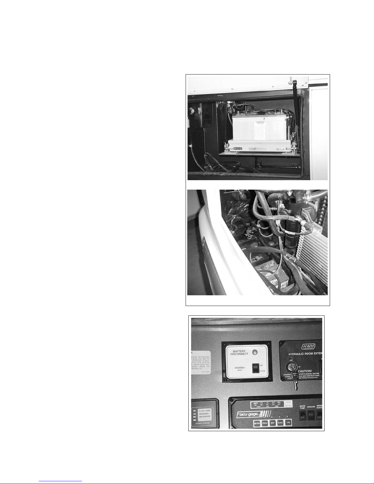
COMMANDER / EMBASSY
10.3 12 VOLT DC SYSTEM
The DC voltage system in your motorhome consists of two separate and yet connected battery systems:
1. The automotive batteries
2. The auxiliary or motorhome batteries
10.3.1 AUTOMOTIVE BATTERIES
These are used to operate the starter, the automotive
accessories and all the controls found on the instrument console. Included are the auto heater fans, the
exterior lights, the horn, speed control, windshield
wipers, etc..
It is recommended that the automotive battery cables
be disconnected when storing the unit for an extended period of time.
IMPORTANT
Removing battery cables from the automotive (chas-
sis) battery can clear the engine/transmission logic
modules. These modules will recalibrate themselves
once the vehicle is reconnected to the 12 volt system
and the engine is started.
Commander
10.3.2 AUXILIARY BATTERIES
These supply power to all the 12-volt lights and equipment in the living area of your motorhome. Included
in this would be vent and exhaust fans, 120-volt generator starter, water pump, furnace fan, interior lights,
holding tank and water level gauges, etc.. These
batteries may provide starting power to your engine
in case the automotive batteries are dead. Refer to
“Auxiliary Start Switch” in this case.
These batteries are “deep cycle” RV batteries designed
to provide power over a long period of time and to
stand up under the frequent drain and recharge conditions of a camping vehicle.
The motorhome has an easy access Auxiliary battery
disconnect. On Commanders, this disconnect is located in the overhead cabinet above the entrance door.
By switching this disconnect to the store position, all
12-volt coach accessories, lights, and appliances will
be disconnected. On the Embassy a manual switch is
located under the front hood.
Embassy
Fig. 10-9 BATTERY LOCATION
Fig. 10-10 AUXILIARY BATTERY DISCONNECT
(COMMANDER ONLY)
10-7
Page 82
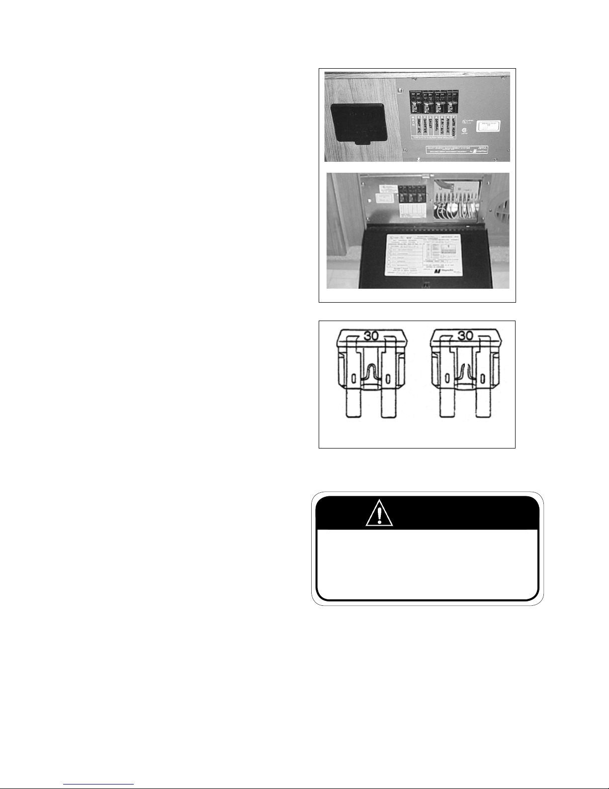
COMMANDER / EMBASSY
10.3.3 12 VOLT COACH FUSES
All 12-volt circuits are protected by either a circuit
breaker or a fuse in the control panel. When a
breaker trips or a fuse blows, shut o all appliances or
lights on the aected circuit and reset the breaker or
replace the fuse with a new one of the same amperage. The label on the panel identies both the fuse
amperage and the applicable circuit.
The fuse panel is located next to the circuit-breaker
panel, below the refrigerator.
10.3.4 BATTERY MAINTENANCE
Commander
Your batteries are reservoirs of 12-volt electrical energy. Whenever energy is removed from the battery it
has to be replaced in order for the battery to continue
functioning. This energy is restored by the engine alternator whenever the engine is running or by the RV
charging system when plugged into a 120-volt power
source.
1. Problems:
Two conditions can destroy the function of a
battery. One is called sulphating in which a layer
of sulphate crystals collects on the lead plates
inside the battery. This can happen when a battery is stored in a discharged state. This situation
requires replacement of the battery. The second
is freezing. A battery must be kept at almost full
charge to prevent the liquid electrolyte inside the
battery from freezing.
2. Prevention:
a. Disconnect the battery cables during long
periods of storage.
b. Hook up a battery charger at least once a
month during long periods of storage.
3. Long Term Storage:
If you do not intend to use your motorhome for a
longer period of time it might be a good idea to
remove the batteries from the motorhome and
store them in a cool dry location on a wood or
rubber pad. The batteries shoud be charged once
a month in order to prolong their life.
Embassy
Fig. 10-11 FUSE PANEL
Good
Fig. 10-12 FUSES
4. Additional maintenance suggestions:
Blown
WARNING
Do not allow battery electrolyte to contact skin, eyes,
fabrics, or painted surfaces. The electrolyte is a sulphuric
acid solution which could cause serious personal injury
or property damage. Wear eye protection when working
with batteries.
a. Check the external condition of the battery
monthly. Look for cracks in the cover and
case.
b. Make sure batteries are always securely fas-
tened down.
c. Make sure battery clamps are tight and free of
corrosion.
10-8
Page 83
COMMANDER / EMBASSY
WARNING
Remove rings, metal watchbands, and other metal jewel-
lery before working around a battery. Use caution when
using metal tools. If a tool contacts the battery termi-
nals or metal connected to them, a short circuit could
occur which could cause personal injury or re.
d. Keep the battery and terminals clean. Ac-
cumulations of acid lm and dirt may permit
current to ow between the terminals and
discharge the battery.
e. To clean the battery, wash it with a diluted
solution of baking soda and water to neutralize any acid present, then ush with clean
water. Foaming around terminals or on top of
the battery is normal acid neutralization.
NOTE
Make sure you don't allow
any baking soda solution to
get into the battery. This can
neutralize the battery acid.
f. Dry the cables and terminals before reinstall-
ing them, and don't use grease on the bare
metal inside the cable terminals to prevent
corrosion. Grease is an insulator. Electricity
will not ow through it. A plastic ignition
spray will protect the terminals after you have
cleaned and reinstalled them.
g. Whenever batteries are removed and re-
placed make sure the positive and negative
cables are attached to the correct terminals.
(Positive to positive and negative to negative). The same is true when using a “booster
battery” or a charger. If you use a “fast charger”, disconnect the cables from your battery.
Do not attempt to recharge a frozen battery.
h. If you do not have maintenance-free batter-
ies, check the battery uid level and ll with
distilled water if necessary. Do not overll.
i. Have the specic gravity of the battery uid
checked when you have your vehicle serviced.
10-9
Page 84
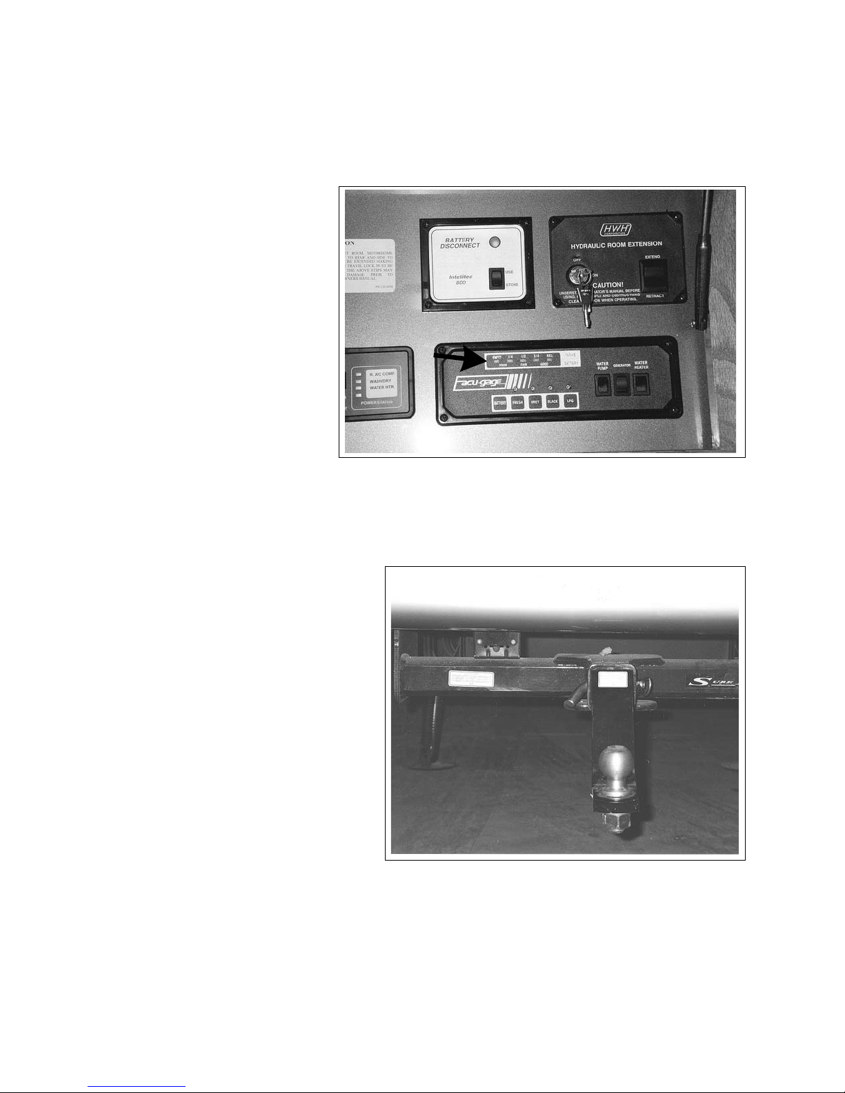
COMMANDER / EMBASSY
10.3.5
You will nd a gauge on your control panel
which tells you the level of charge in your
coach or auxiliary batteries.
BATTERY CONDITION METER
Fig. 10-13 BATTERY CONDITION METER
10.4 TRAILER WIRING CONNECTOR
Your motorhome is ready for trailer or car towing. It has a wiring connector plug at the back
for quick hook-up.
Refer to the labeled diagram of the various
terminals in the plug. These are standard for all
7-pin trailer plugs.
If you intend to tow a trailer with electric brakes
a brake controller is required. This can be installed by your dealer.
If you intend to tow a trailer with electric brakes
a brake control kit is required. This can be installed by your dealer.
Fig. 10-14 TRAILER WIRING CONNECTOR
10-10
Page 85
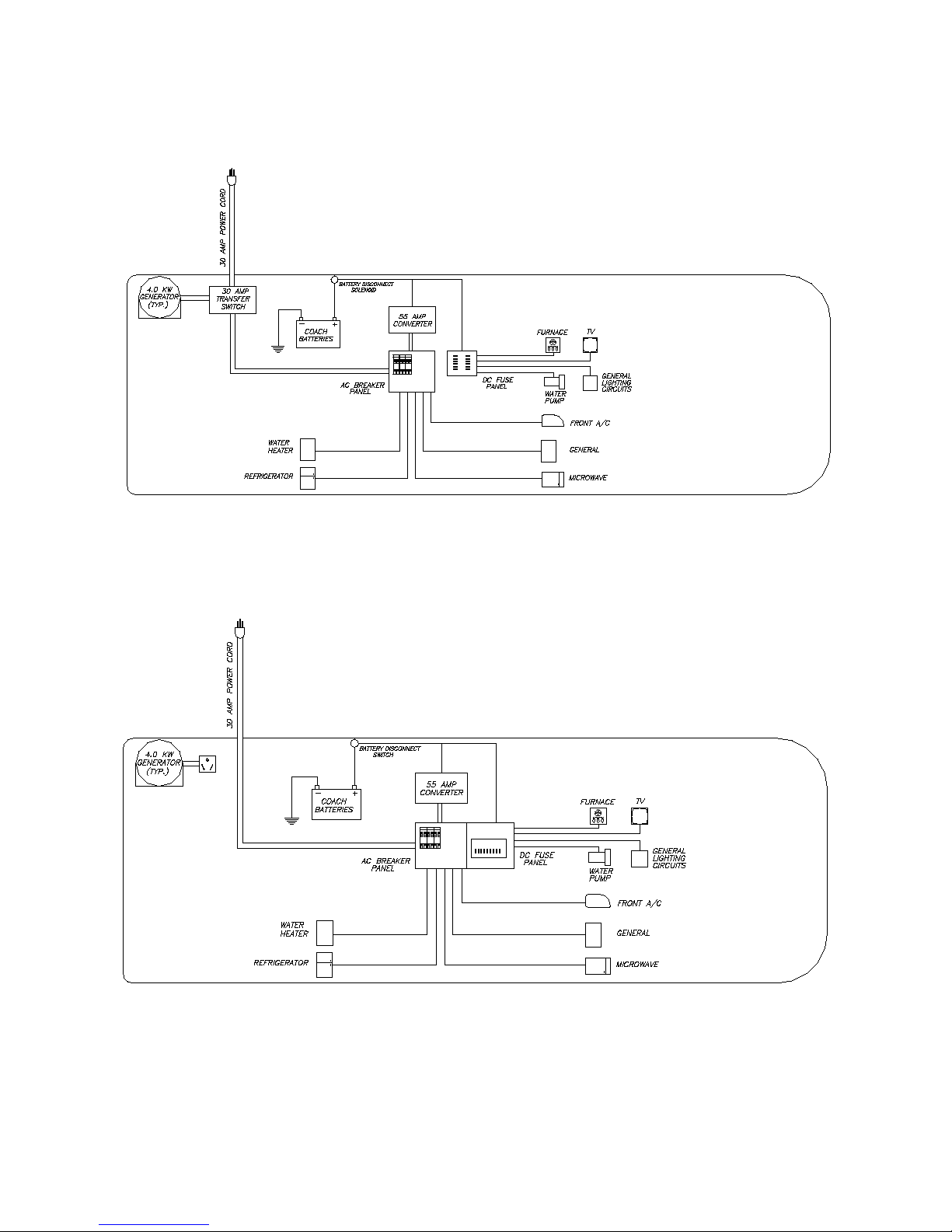
COMMANDER / EMBASSY
10.5 ELECTRICAL SCHEMATICS
30 AMP SERVICE COMMANDER
30 AMP SERVICE EMBASSY
10-11
Page 86
COMMANDER / EMBASSY
10.6 ELECTRIC CIRCUIT PANELS
10.6.1 EMBASSY
Fig. 10-15 EMBASSY CIRCUIT PANEL
10.6.2 COMMANDER
Fig. 10-16 COMMANDER CIRCUIT PANEL
10-12
Page 87
COMMANDER / EMBASSY
10.6 VEHICLE 12-VOLT FUSE PANELS
Access Panel
Fig. 10-17 EMBASSY FUSE PANEL
Fig. 10-18 COMMANDER FUSE PANEL
10-13
Page 88

11 LP GAS SYSTEM
COMMANDER / EMBASSY
LP (Liqueed Petroleum) gas is a colorless gas compressed into liquid form for easy transportation and
storage. It is the energy source for your range, oven,
furnace, water heater, and an alternate fuel source for
your refrigerator.
It is an excellent fuel source and both safe and economical when used properly.
CAUTION
These instructions are provided as a general
guideline only and may not be complete. To
ensure proper service and safety, always take
your motorhome to an authorized Triple E
service center.
11.1 SAFE USE OF LP GAS
The LP gas system is designed and built to adhere to
federal government and industry regulation requirements.
Many safety devices and backup systems have been
built in to assure complete safety. Some of these
include: tank overow valves, LP gas detector, and
carbon monoxide (CO) detectors. As well, LP gas
contains an odor additive so that it can be more easily
detected.
Observe the following precautions for the safe use of
LP gas.
1. Familiarize yourself with the odor of LP gas. If you
suspect a leak, turn o the LP gas supply immediately and determine the source of the leak with
the help of qualied service personnel.
2. Do not tamper with any part of the LP gas system,
piping or regulator. Service and maintenance
should be performed only be qualied personnel.
5. Turn o the LP gas supply valve when not using it.
6. The tank supply valve is designed to be tightened
by hand only. If the valve requires a wrench for
tightening it is defective and should be replaced.
7. Tanks should never be lled above the 80 % level.
LP gas requires room to expand.
8. Make sure all appliance vents are open and free of
obstruction when using the LP gas system.
9. Do not lock LP tank compartments. Recreational
vehicle industry standards require that all LP gas
valves must be readily accessible at all times in
case of emergency.
10. When drilling holes in walls or attaching objects
be careful not to damage any gas lines or electrical wiring.
11.2 HOW LP GAS WORKS
There are two types of LP (Liqueed Petroleum) gas
- propane and butane. Both are compressed into a
liquid for easier transportation and storage. Common
names used are tank gas, bottle gas or simply LP.
In the tank, LP is in the form of a liquid under very high
pressure. As it is released, it changes to a vapor or gas
and expands to a much greater volume.
Caution should be exercised when temperatures fall
below -40 degrees C (-40 degrees F). At temperatures
this low the liquid propane will not vaporize and you
could be without propane at these lower temperatures.
3. Do not use natural gas in a LP gas system.
4. Check the entire system for leaks every time the
tanks are lled. Take time regularly to inspect the
system for leaks.
11-1
Page 89
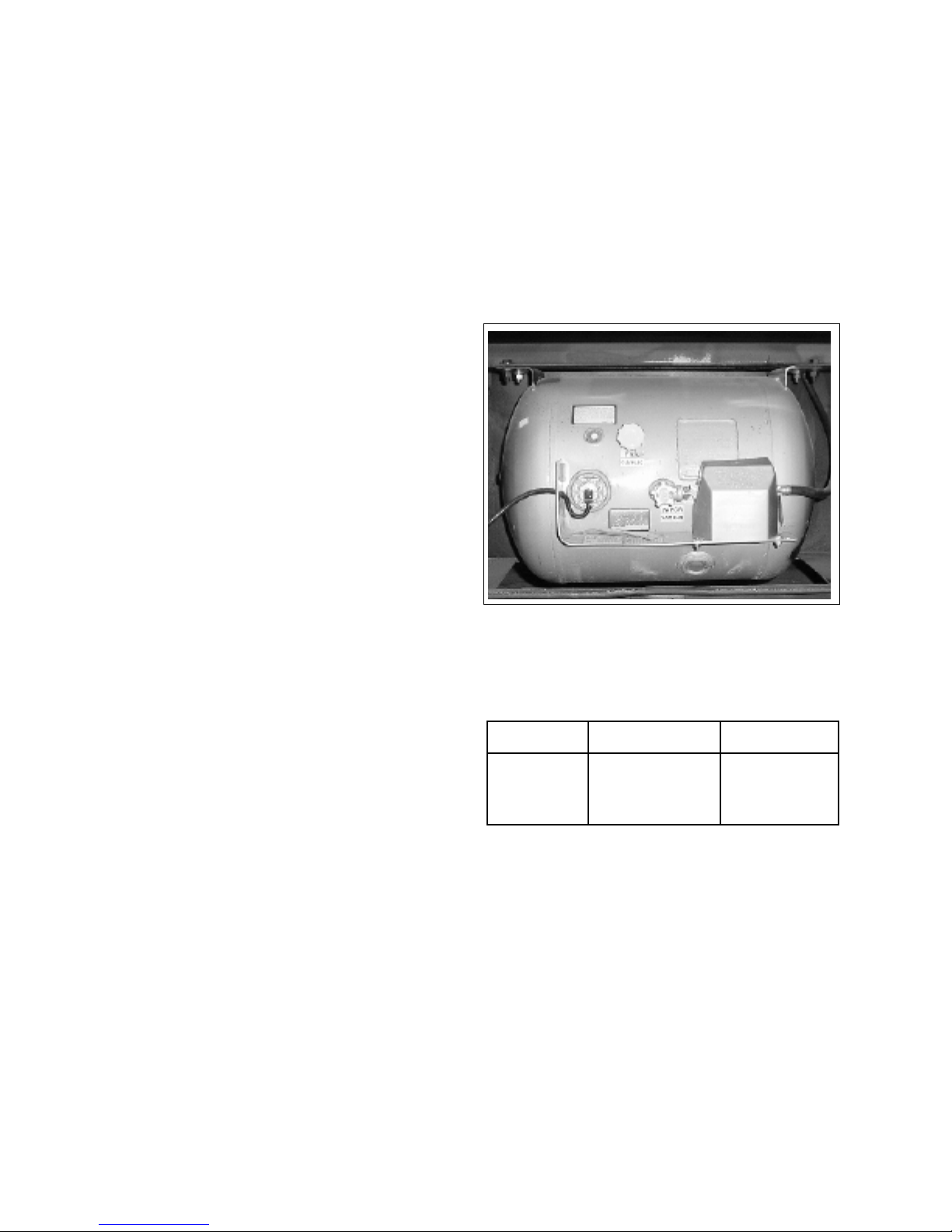
COMMANDER / EMBASSY
11.3 SELECTING FUEL TYPES
Butane burns at a much higher temperature than
propane but will not change from a liquid to a gas at
temperatures below 32 degrees F or 0 degrees C. Propane, on the other hand, burns at a lower temperature
and will continue to convert from a liquid to a gas at
temperatures as low as -40 degrees F or -40 degrees C.
LP dealers will normally provide only the type of gas
commonly used and suited to the climate in their area.
If you travel from a warmer part of the country to a
colder area you may want to check to make sure you
have the right type of LP gas.
11.4 LP TANK SYSTEM
The storage tank for the LP gas is mounted
underneath the motorhome attached to the vehicle
frame. It is accessible only from outside the vehicle.
The tank valve is located near the top center of the
tank next to the regulator. Before opening the supply
valve, make sure all controls for the various appliances
are in the OFF or PILOT OFF position. This is to prevent
any LP gas from accumulating in the motorhome.
11.5 LP TANK CAPACITY
Fig. 11-1 TANK LOCATION
The tank size is the approximate usable volume which
is about 80% of the total tank volume.
Commander Embassy
Tank Size 25.3 (95.8) 25.3 (95.8)
Gal (liters)
Propane Tank Capacities
11-2
Page 90
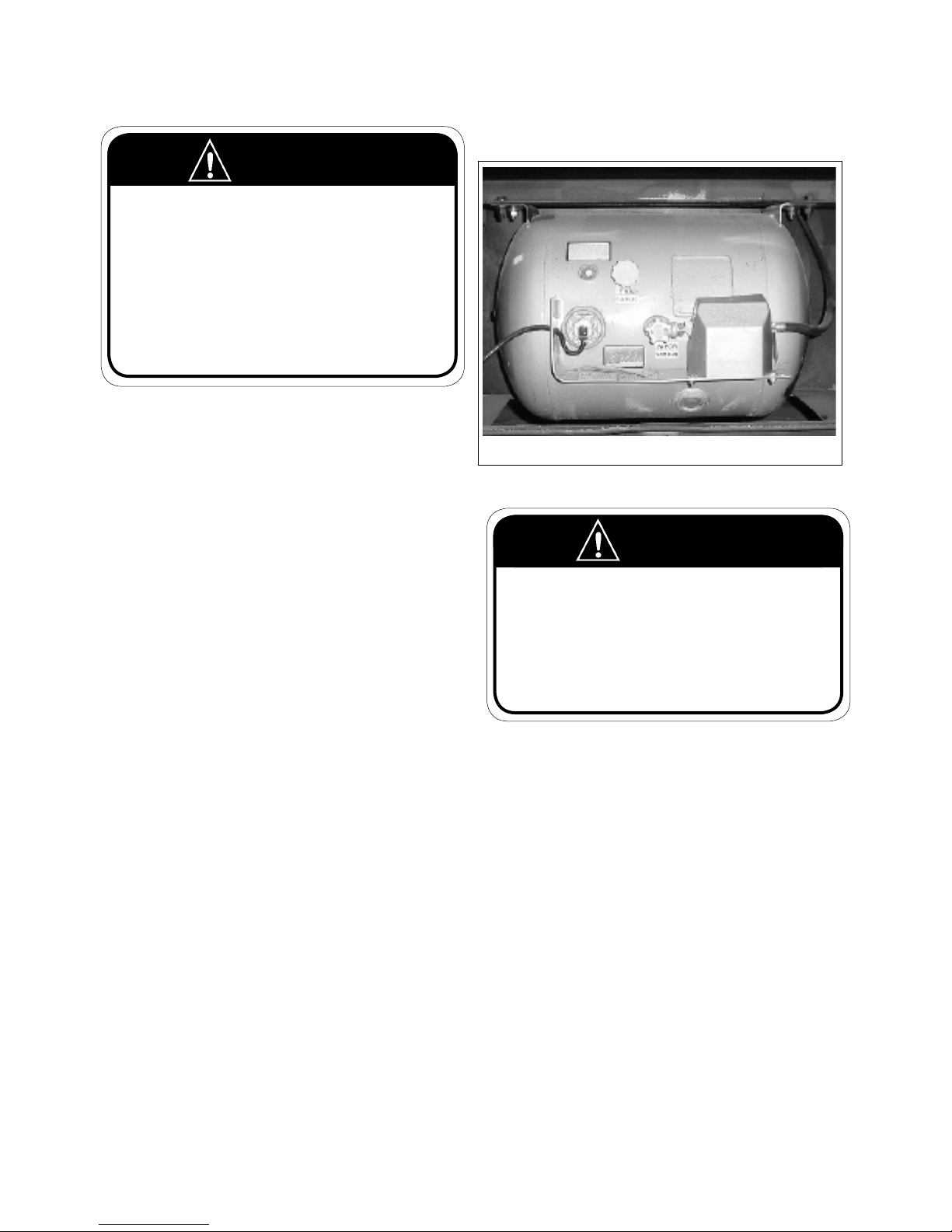
COMMANDER / EMBASSY
11.6 REFILLING LP TANK
WARNING
1. Never overll the LP gas tank.
2. Make sure your vehicle is level when lling the tank.
3. Make sure all pilot lights are OFF before refuelling any of
the gas tanks on your motorhome.
4. Do not smoke or have any open ame in the area where
refuelling is taking place.
5. When testing for leaks in the LP system use a soap and
water solution. Never use an open ame to test for leaks.
6. Never ll the LP tank when either the engine or the generator is running.
7. Keep all protective covers and caps in place.
Simply open the baggage door, and ll the container
via the ll-in valve as indicated on the container.
Filling should always be done by a qualied service
attendant.
Shut o all pilot lights and the control valve on the LP
gas container when lling the container.
Always rell empty LP gas container as soon as possible.
Do not overll your LP gas container. Stop lling when
liquid appears at the overow valve, this indicates that
the tank is full which contacts the liquid level at 80%
of container capacity allowing 20% for expansion.
Check after each lling by opening the overow valve
and bleed gas in well-ventilated area until white liquid
stops. Overlling may cause damage to regulator and
cause malfunction of LP gas appliances.
b
a
c
a. Fill b. Overow c. Vapor Outage
Fig. 11-2 LP GAS TANK
WARNING
Remind the service attendant to use the 80% overow
valve when refuelling. Space must be left in the tank for
vaporization and expansion.
Never carry LP or any other ammable liquid containers in your motorhome. Gases may inadvertently be
discharged into the room which could result in re or
explosion.
IMPORTANT
The LP tank has an automatic 80% stop-ll
device to prevent over lling of the tank.
The tank is permanently mounted to the motorhome
frame. Therefore the vehicle must be taken to a fuelling station to be lled. When liquid LP gas appears at
the overow valve, the tank is full.
LP gas stations are found in all parts of the country.
Check with the Yellow pages in your telephone book
if you have trouble nding a station. Look under “GasLiqueed Petroleum-Bottled and Bulk” or ”Propane”.
11-3
Page 91
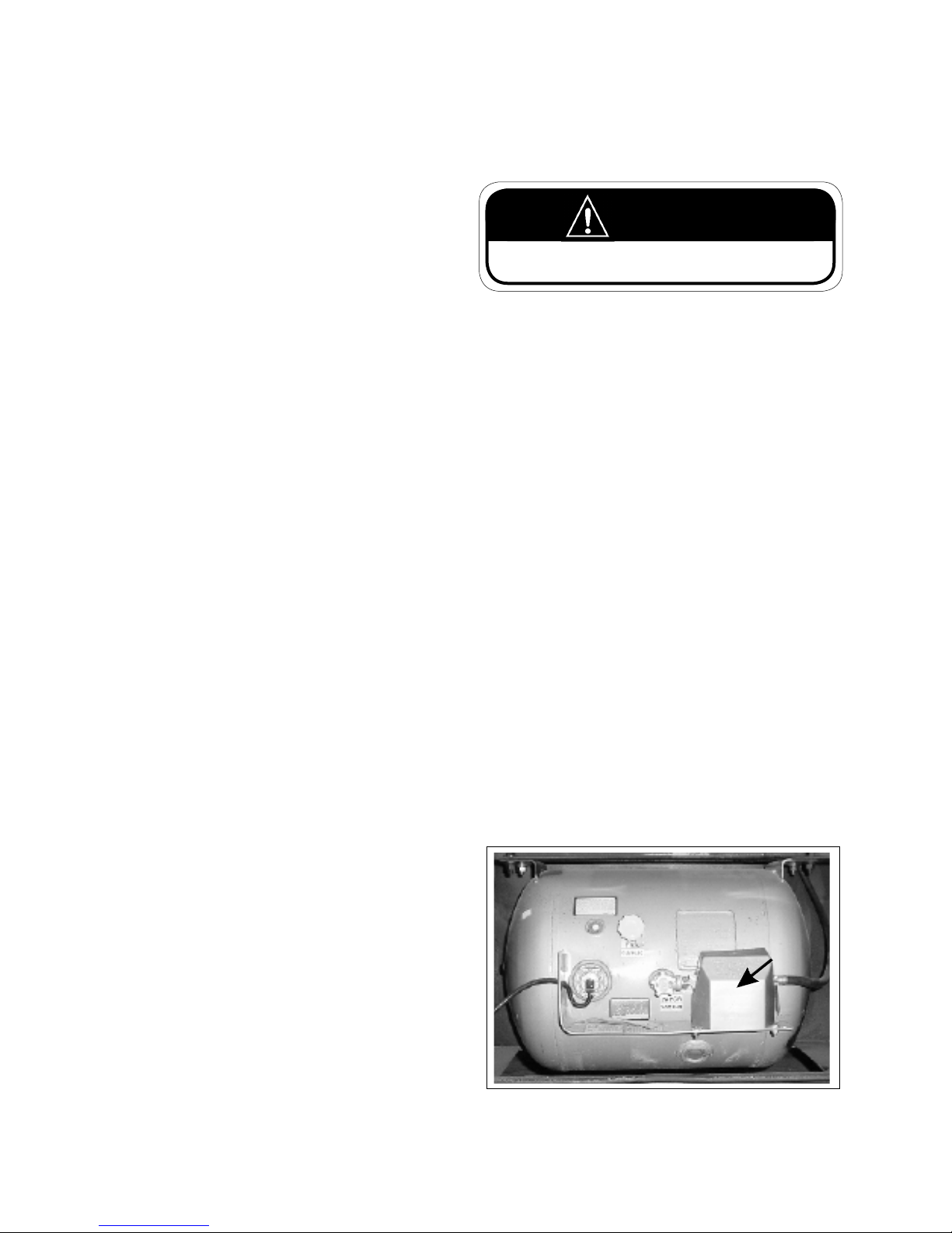
COMMANDER / EMBASSY
After tank has been lled:
1. Check all container and line connections periodically to be sure they are tight. When testing for
leaks, use soapy water (never a match). LP gas has
a distinct garlic odor.
control valve closed when not in use even when the
tank is empty. This helps prevent condensation from
forming. Hold a light bulb near the regulator to thaw
it.
2. If LP gas fumes are noticed at any time, the cause
should be determined and corrected without
delay. In winter, always have methyl alcohol
added to your LP container for winter operation to
prevent freeze-up.
3. Before opening the control valve at the LP gas
container, check that controls for all gas appliances are in the o position. If this is not done, LP
gas could accumulate inside the vehicle creating a
re or explosion hazard.
4. LP gas is also potentially lethal if inhaled.
11.7 AIR IN THE LP TANK
If your LP appliances burn poorly or do not stay lit
even though you are sure you have plenty of fuel, you
may have air trapped in the tank. The air will eventually escape along with the LP gas but it may be necessary that you have your tank purged of air by the LP
gas dealer. During the tanks rst ll, ensure that the
tank is purged.
WARNING
Do not use an open ame or a heat lamp to thaw out
regulator.
If moisture in the tank is a recurring problem, you may
ask your LP gas dealer to inject a small amount of methyl alcohol into the tank to absorb the moisture.
Liquid Petroleum vaporizes quickly and easily at
warmer temperatures. Under cold conditions this
process slows down dramatically. When large
amounts of fuel are required when using the furnace,
for example, the fuel may not vaporize rapidly enough
to keep all the appliances going at a high level. In this
case you may have to reduce the consumption of fuel
by lowering the temperature setting on the furnace,
reduce the consumption of hot water, turn up the
temperature setting on your refrigerator or switch
from LP to electric where possible.
The regulator is preset. Do not attempt to adjust it.
This should only be done by an authorized service
outlet. The regulator should not be exposed to the
elements.
11.8 TRAVELLING LP GAS
In some jurisdictions it is illegal to transport LP gas
on certain roads or through tunnels. Check state or
provincial regulations to make sure your trip will not
be halted or impeded unexpectedly as a result.
11.9 REGULATOR
The LP tank regulator has a plastic cover to protect
it from the weather. This should never be removed
except by qualied service personnel.
The pressure regulator has a vent hole on the under
side. The regulator must always be positioned with
the vent facing downward. Make sure this vent hole is
open and not obstructed in any way.
During freezing weather it may happen that a regulator may freeze up. This happens when there is a small
amount of moisture in the fuel (even though every
precaution is taken by gas dealers to prevent this from
happening). To help avoid this situation, keep the
If the LP gas components malfunction the possible
cause could be:
1. The LP gas container may be overlled.
2. There may be impurities in the propane.
3. The LP Regulator could be defective.
Fig. 11-3 REGULATOR
11-4
Page 92
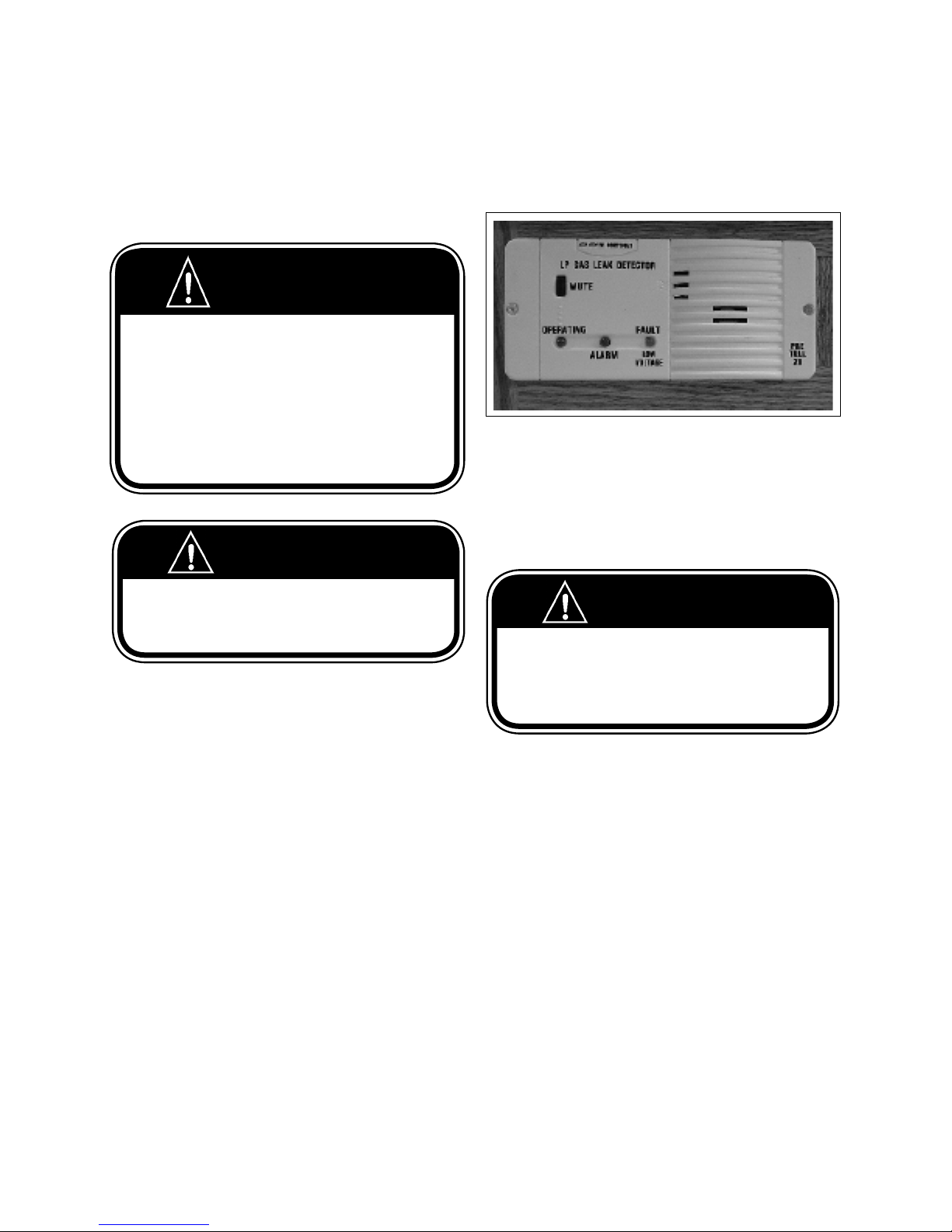
COMMANDER / EMBASSY
11.10 LP GAS LEAKS
If you ever smell LP gas in the vehicle or the detector
alarm sounds, follow the instructions carefully.
WARNING
IF YOU SMELL GAS
1. Extinguish any open ame, pilot lights and all smoking material.
2. Do not touch electrical switches.
3. Shut o thegas supply at the container valve(s) or gas supply connection.
4. Open doors and other ventilating openings.
5. Leave the area until the odour clears.
6. Have the gas system checked and leakage source corrected before
using again.
WARNING
11.11 LP GAS DETECTOR
A standard LP gas detector has been installed in your
unit.
Fig. 11-4 LP GAS DETECTOR
NOTE
Your unit is not equipped with an automatic propane shut-o valve.
Please refer to manufacturer's manual for further
instructions.
Do not bring or store LP gas containers, gasoline, or
other ammable liquids inside the vehicle because a re
or explosion may result.
WARNING
It is not safe to use cooking appliances for comfort
heating. Cooking appliances need fresh air for safety
operation. Before operation:
1. Open overhead vent or turn on exhaust fan.
2. Open window.
This warning label has been located in the cooking
area to remind the user to provide an adequate supply
of fresh air for combustion. Unlike homes, the amount
of oxygen supply is limited due to the size of the recreational vehicle, and proper ventilation when using
the cooking appliance(s) will avoid dangers of asphyxiation. It is especially important that cooking appliances not be used for comfort heating as the danger
of asphyxiation is greater when the appliance is used
for long periods of time. Failure to comply could result
in serious injury or death.
11-5
Page 93
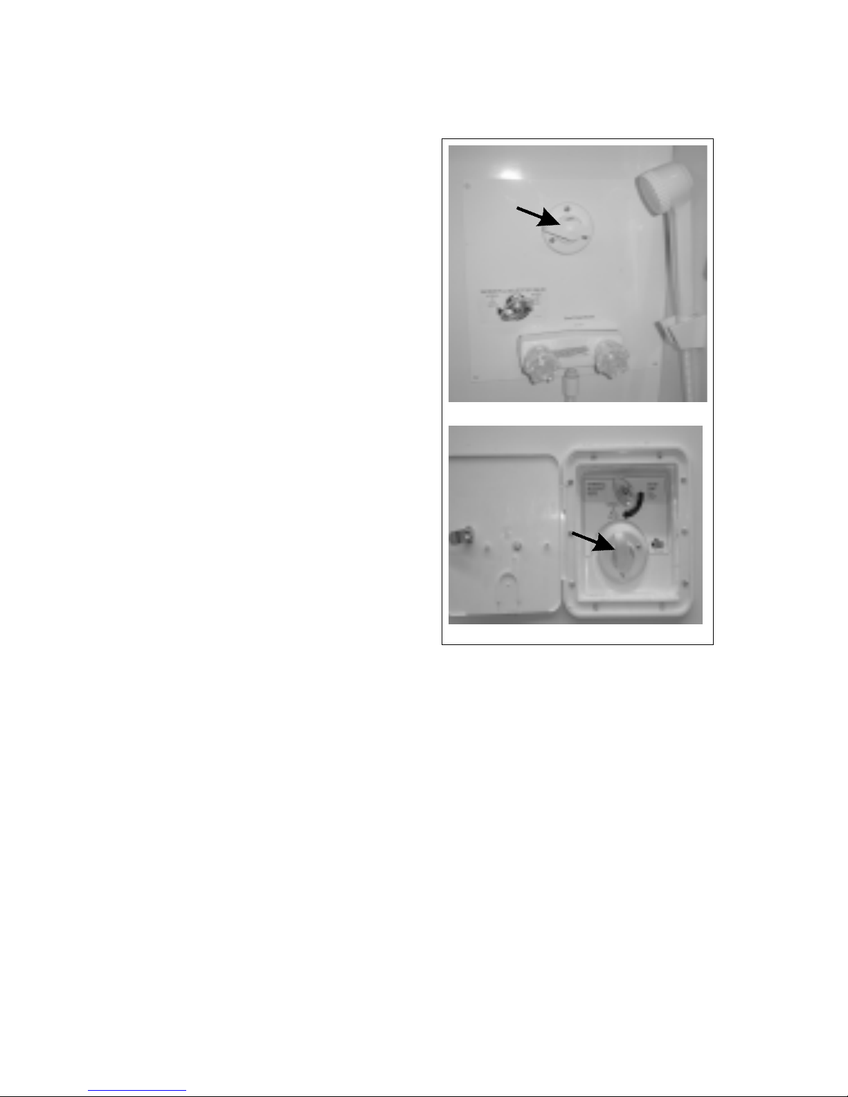
COMMANDER / EMBASSY
12 WATER/PLUMBING
SYSTEM
Your motorhome is designed with a fresh water, grey
water, black water systems and associated plumbing
to handle all of the water and waste requirements. Review this section carefully to understand each system
and how they function together.
12.1 FRESH WATER SYSTEM
There are two sources for fresh water in your
motorhome:
1. A water tank located within your motorhome.
2. By connecting to “city water” by means of a water
hose.
Both can supply water to the sink, shower, bathroom,
toilet and the water heater.
The water system built into your motorhome provides
full service similar to the system used in your home. A
12-volt self-priming pump draws water from the fresh
water storage tank to supply presurized water to the
system. An automatic pressure switch, located in the
water pump maintains a positive line pressure.
Commander
Commander units:
The city water connection is located in the utility
module on the road side of the coach. The water
pump and lter are also located in the utility module.
The water tank is either installed under the rear bed or
under the oor depending on the model.
The utility compartment located on the drivers side of
the vehicle contains, the water pump, the potable city
water ll selector valve, winterization bypass valve, and
the water tank drain.
Embassy units:
The City Water connection is located on the driver side
exterior wall.
The water pump and lter and the water tank drain are
located next to the water tank under the rear bed.
Embassy
Fig. 12-1 CITY WATER HOOK-UP
12-1
Page 94
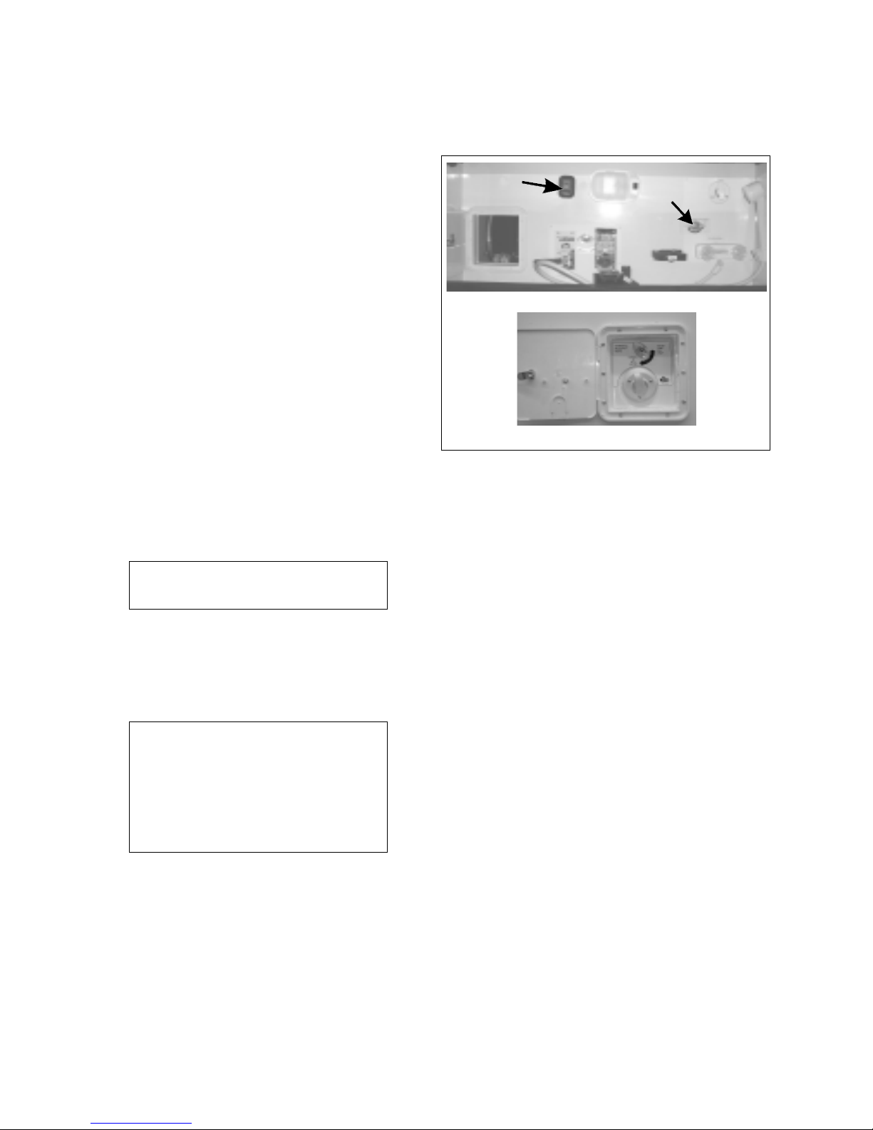
COMMANDER / EMBASSY
12.1.1 FRESH WATER TANK
FILLING PROCEDUR
The water tank is not a pressure vessel. The lling
procedure is done via a water pressure system and
cannot be done without available water under
pressure. Make sure the vent/overow drain located
underneath the tank area is open, free and clear of
any obstruction before attempting to ll the tank. A
blocked vent during lling could cause serious damage
to the tank and even the underoor structures.
When lling fresh water tank:
1. Connect water hose to the city water inlet
connection.
2. Set the water pump switch to the o position.
3. Turn systems valve to “Tank Fill” position.
4. Turn on water supply.
5. Check the Monitor System inside the motorhome
for levels as the tank is lling. When the tank is
close to full, check for overow at the overow
drain. Turn the supply o as soon as water ows
from the drain.
E
IMPORTANT
Never allow a full ow at the overow.
6. Turn the systems valve back to normal, after
external supply is turned o.
7. Turn pump switch back to on and the system is
ready to be used.
IMPORTANT
If you are starting from a dry system or
if some faucets have been open dur-
ing the tank lling procedure, you may
want to slowly open all faucets one at a
time to allow any trapped air to escape
from the system.
Pump Switch
Commander
Embassy
Fig. 12-2 FRESH WATER TANK FILL (INLET)
CITY WATER HOOK-UP
Systems
Valve
12.1.2 WATER PUMP
The water pump is designed to supply water from the
fresh water tank to the various areas of your motorhome on demand. The main switch for the pump is
located on the Monitor Panel in the cabinet above the
entrance door. With the pump switch in the 'on' position the pump comes on automatically and pressurizes
the various water lines when a faucet is opened.
Commander units have a remote switch on the Galley
and Vanity cabinet face as well as in the service module. With the main switch in the 'on' position press the
remote switch once to switch the pump on and press it
again to turn it o.
The water pump has an inlet screen type lter mounted to the body. If water ow in your unit deteriorates,
clean out this screen. (See pump owners manual for
details)
12-2
Page 95
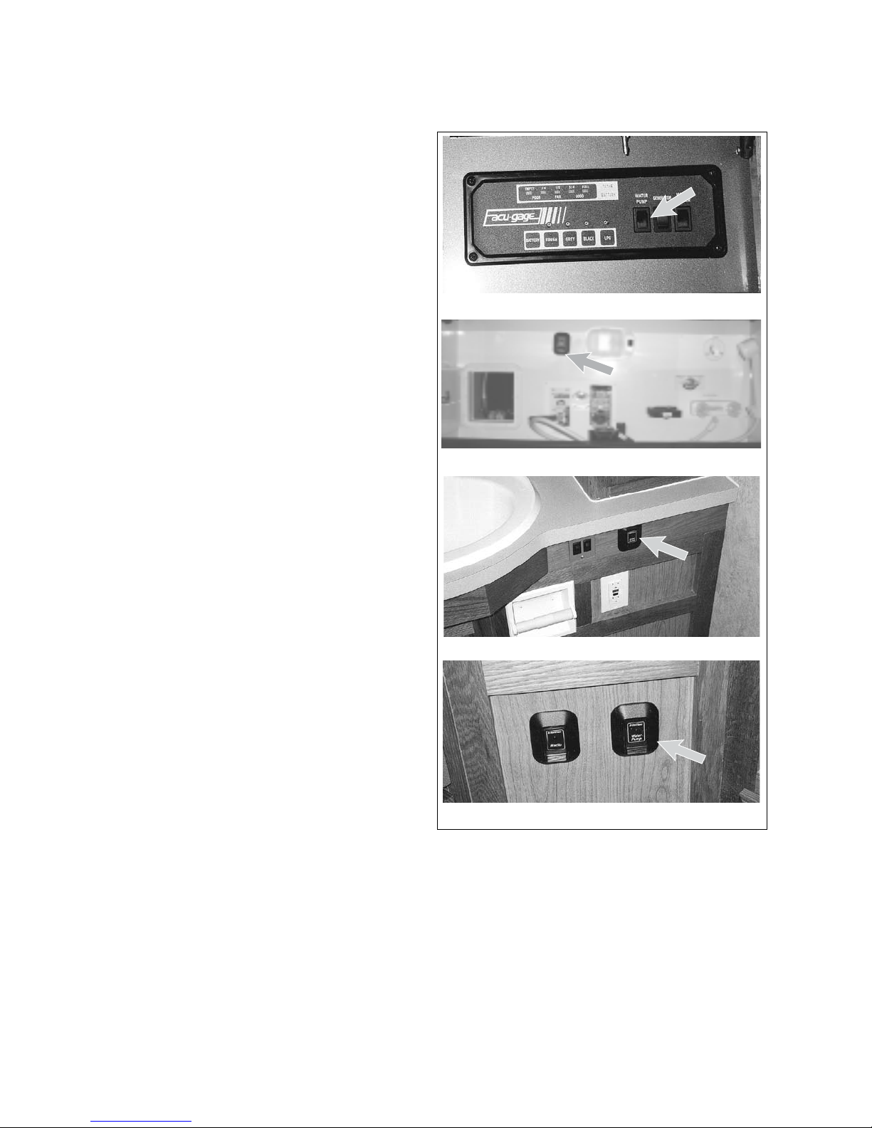
COMMANDER / EMBASSY
12.1.3 WATER PUMP SWITCH
The master switch for the water pump is located at
the control panel above the entrance door. When this
switch is in the on position, the pump will automatically activate when any faucet, shower or toilet is
being used. On the Commander, there are switches
located at the galley, in the bathroom and at the exterior shower that can be used to turn the pump on or
o. This makes it more convenient to use the system
without having to go to the master switch every time.
It is recommended that the pump switch be turned
o whenever leaving the motorhome for any period
of time or while driving. A slow leak in a faucet or
connection could drain both the water tank and the
battery.
Master - Control Panel
External Compartment (Commander only)
Bathroom (Commander only)
Galley (Commander only)
Fig. 12-3 WATER PUMP SWITCHES
12-3
Page 96
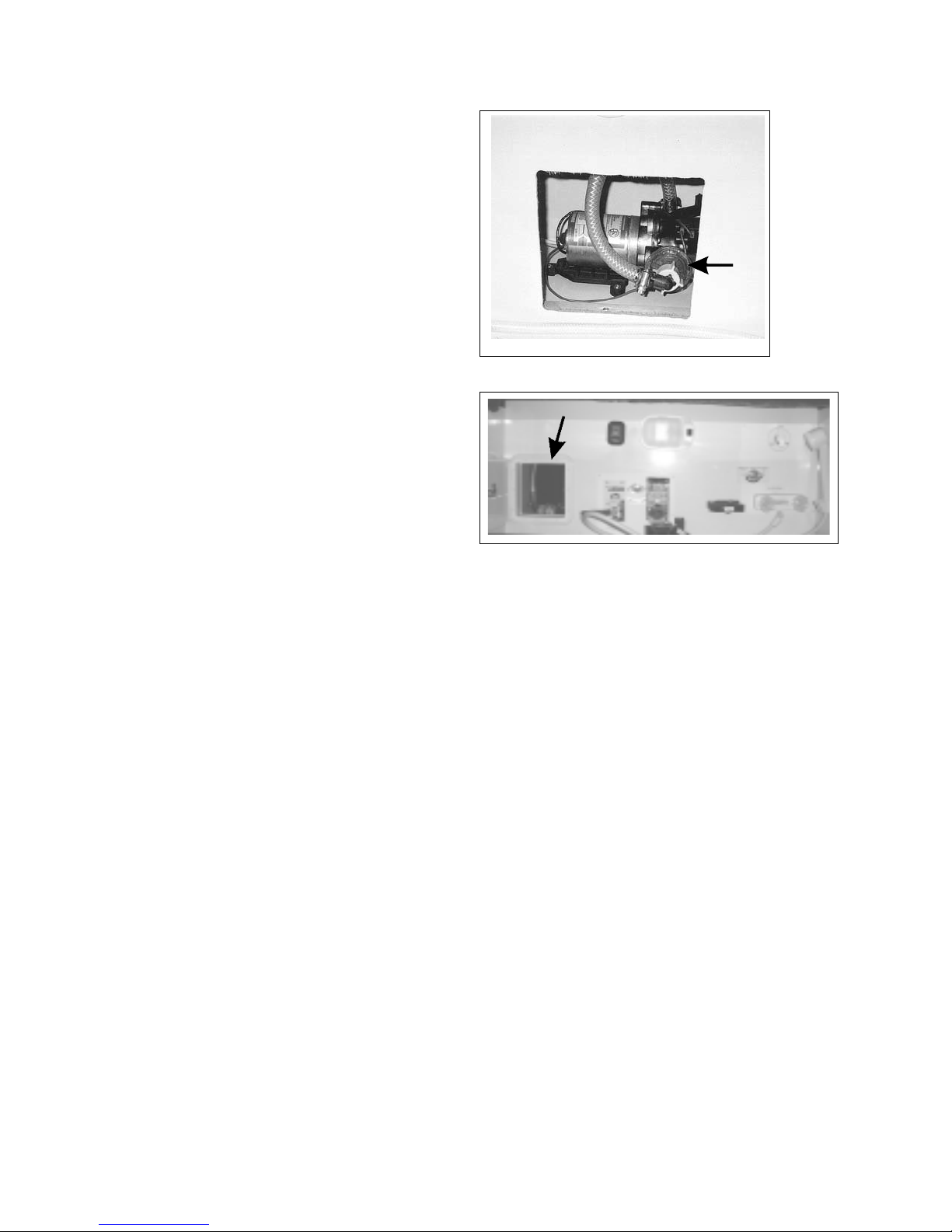
COMMANDER / EMBASSY
12.1.4 WATER PUMP FILTER
Before water can enter the various outlets in your
motorhome it ows through a water lter. This lter is
located on the water pump. The water pump is located
either in the service module on the Commander and
under the bed on the Embassy.
Check the water lter periodically and clean or replace it
at least annually to assure a clean supply of water.
12.1.5 WATER SYSTEM ACCESS
The water system compartment is designed with a hole
in the bottom to provide access to the compartment for
the water line. Route the hoses through this hole and
close the compartment door when at a campsite.
Fig. 12-4 WATER FILTER
12.1.6
1. Make sure all drain valves are closed including the
2. Turn water pump switch o.
3. Fill water tank.
4. Open faucets, both hot and cold.
5. Turn pump switch on.
6. Close each faucet (cold and hot) as soon as water
7. Check to see that pump stops after all faucets are
8. Pump is now ready for automatic operation. It will
WATER PUMP INITIAL START-UP
water heater valve.
ows steadily.
closed.
start whenever a faucet is opened.
Fig. 12-5 ACCESS DOOR (COMMANDER ONLY)
12-4
Page 97

COMMANDER / EMBASSY
12.1.7 WATER PUMP
TROUBLE SHOOTING
1. If pump will not prime:
a. Make sure there is water in the tank.
b. Make sure the battery is not run down.
c. Make sure there are no kinks in the inlet
hose.
d. Make sure all inlet ttings and connections
are air tight.
e. Make sure water selector valve is set to nor-
mal.
f. Check for clogged lines.
2. If water pressure drops:
a. Check faucets and connections for leaks.
b. Make sure faucet aerators and lters are
clean.
c. Make sure there is water in the tank.
d. Make sure battery is not run down.
3. If pump runs when there is no apparent demand
for water:
a. Make sure all faucets and xtures are shut o
and are not leaking.
b. Check all lines for leaks.
c. Make sure there is water in the tank.
d. Make sure no air is trapped in the system.
e. Make sure the tank ll water selector valve is
set to normal.
4. Disinfection instructions
A. Commander:
1. Place the pick up line (located in the service
module) into a container of pre-mixed disenfectant solution (1/4 cup household liquid chlorine
bleach per 1-gallon of water), use 1-gallon for
every 15-gallons of tank capacity.
2. Turn the winterization valve to winterize
position and ensure all taps are closed. 3.
Open the anti-freeze / disinfectant pick-up direction valve.
4. Switch the pump on to pump the disinfectant solution into the fresh water tank then switch
it o again.
5. Top o the tank with fresh water.
6. Turn the winterization valve to normal use
position.
7. Close the anti-freeze / disinfectant pick-up
direction valve.
8. Switch the pump on and run water from
each faucet, hot and cold, until you detect a
chlorine odor.
9. Leave the solution in the system for at least
4-hours. If you wish to complete this procedure
in 1-hour, double the concentration of household bleach in your solution.
10. After the time has elapsed, drain and ush
the system with fresh water.
12.1.8 DISINFECTION OF
WATER TANK
It is recommended that fresh water systems be disinfected when:
1. the system is new and has not been used before.
2. it's been in storage for a long period of time.
3. in case it has become contaminated.
B. Embassy:
1.Pre-mix a solution of 1/4 cup household liquid
chlorine bleach to 1 gallon of water. Pour this
solution into the garden hose; hook the garden
hose to the city water inlet and ll the tank. (Use
1-gallon for every 15-gallons of tank capacity.)
2. Turn on the pump.
3. Run water from each faucet, hot and cold,
until you detect a chlorine odor.
4. Leave the solution in the system for at least
4-hours. If you wish to complete this procedure
in 1-hour, double the concentration of household bleach in your solution.
5. After the time has elapsed, drain and ush
the system with fresh water.
12-5
Page 98
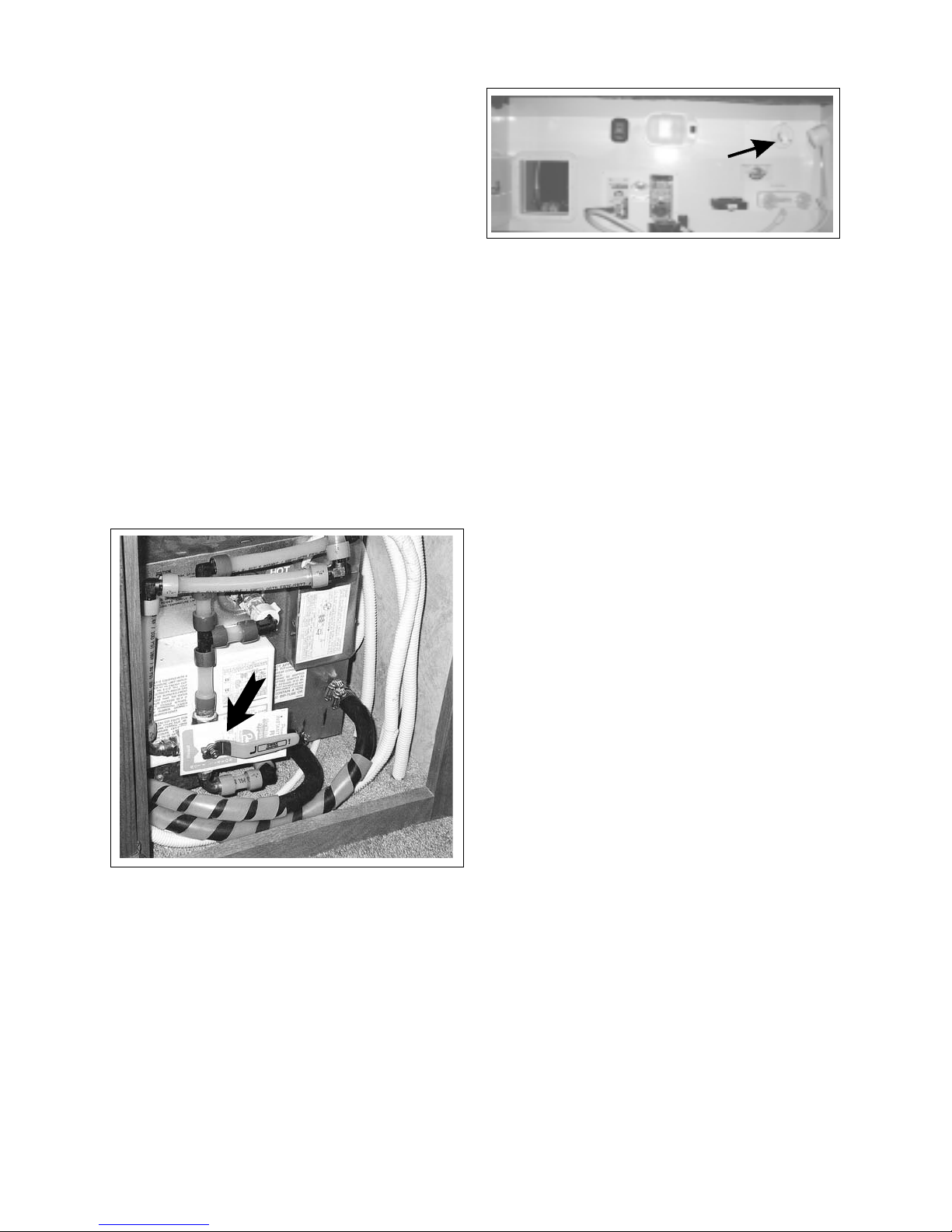
COMMANDER / EMBASSY
12.1.9 EXTERNAL WATER SUPPLY
The external water source will supply your motorhome
water system with water at city pressure when the water
pump is switched o.
1. Connecting:
a. Turn water pump switch to o.
b. Attach garden hose to city water connection
at water ll selection valve. Turn the water
selector valve to "city water".
c. Turn on external water supply.
IMPORTANT
After connecting to the external water supply, open the
faucets in your motorhome slowly and cautiously. Air
trapped in the line can cause the water to splash into
the sink. You may want to drape a wash cloth over the
faucet to prevent excessive splashing.
Fig. 12-6 WATER CONNECTION
(COMMANDER ONLY)
3. Disconnecting:
a. Turn o the external water tap.
b. Relieve water pressure on the line by opening
a faucet in the motorhome.
c. Disconnect hose from the motorhome.
d. Replace the protective plug back over the
water connection.
2. Turn the water heater by-pass valves to
normal to be sure that water enters the
heater and hot water is available for use.
Fig. 12-7 BYPASS VALVE
Water from the external supply is prevented from
entering the water tank and the water pump by
means of a check-valve.
12.2 WASTE SYSTEMS
12.2.1 GREY WATER - WASTE
HOLDING TANK
The drainage from the kitchen sinks, bathtub and
shower pan is collected in a separate grey water holding tank. This tank has its own dump valve but ties
into the same termination valve outlet as the waste
holding tank.
IMPORTANT
If grey water holding tank is allowed to overll, the overow may back up through the bathtub/shower drain.
12.2.2 BLACK WATER - WASTE
HOLDING TANK
The black water holding tank collects all the waste
from the toilet and vanity sink. Before using your
waste holding tank, deoderize it by adding one gallon water and a commercial holding tank deoderizer
through the toilet.
IMPORTANT
If holding tank is allowed to overll, the overow may
back up through the toilet drain.
IMPORTANT
Some campgrounds have an excessively high
water pressure which can cause problems. It is
a good idea to get a pressure reducer from your
RV center and attach it to your incoming external
water supply hose to ensure safe pressure for your
unit.
12-6
Page 99
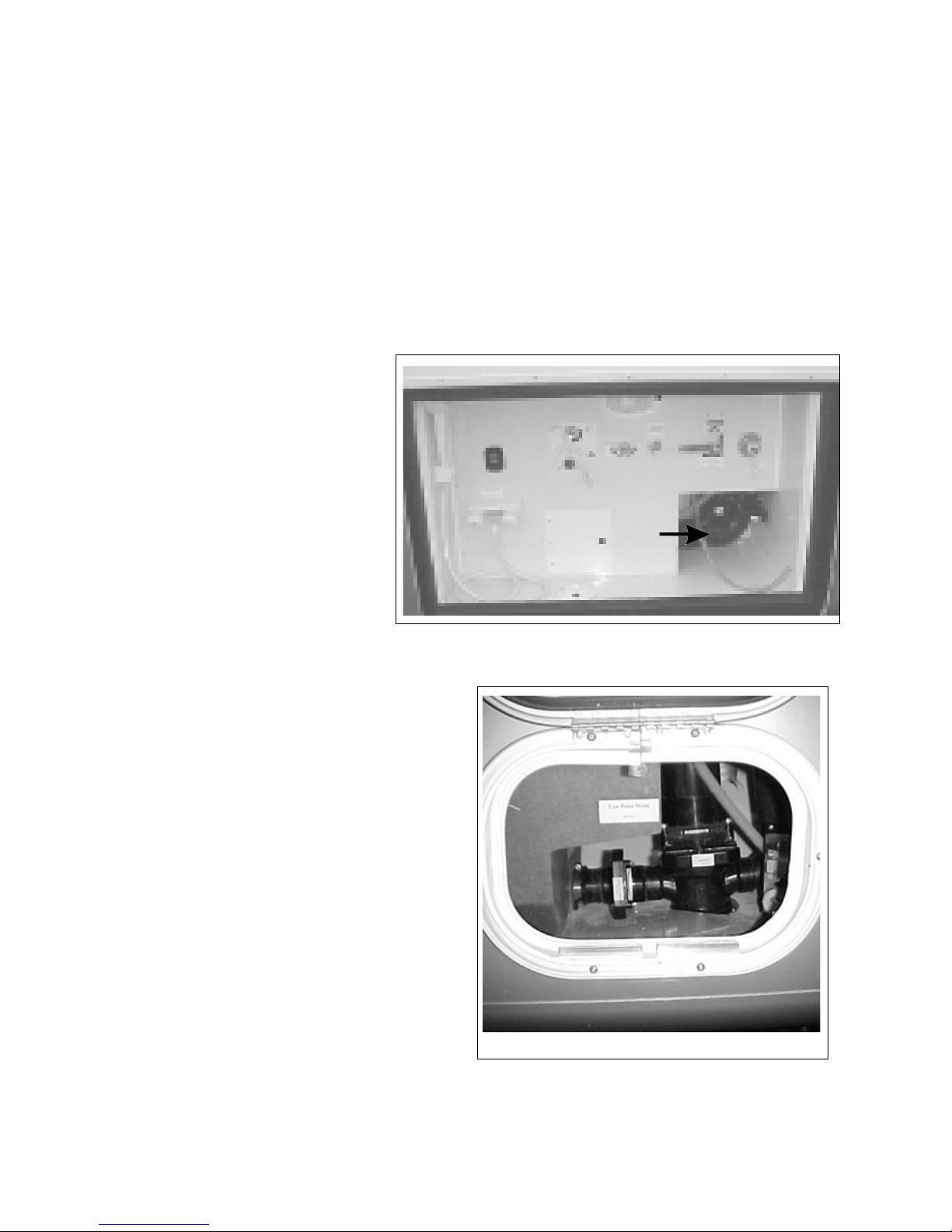
12.2.3 DUMPING HOLDING TANKS
When dumping holding tanks:
COMMANDER / EMBASSY
1. Remove drain hose from storage
compartment.
2. Remove dust cap from drain outlet. Attach drain hose securely.
3. Place the other end of the hose in
sewer opening.
4. Make sure hose is lying at.
Open black water valve with a
quick pull. Move hose about
gently to ensure ow of waste
materials. When tank is empty,
close the valve.
5. After tank has been drained, run
several gallons of fresh water into
the black water tank through
the toilet. Open the dump valve
to ush out any residual wastes.
After the tank has been drained
again, close the valve.
IMPORTANT
Holding tanks should be dumped be-
fore travelling to eliminate unnecessary
weight while driving.
Dumping Valves
Fig. 12-8 DUMPING VALVES (COMMANDER ONLY)
NOTE
Do not open the grey water valve until
black water valve is closed. This will prevent any black wastes from entering the
grey water tank. Grey water also rinses
out any black water residue left inside
the drain hose.
6. Open grey water valve. Close after tank is empty.
7. Add an odor control chemical to the black water
holding tank. These are available at any RV center.
8. Rinse the sewer hose thoroughly and store.
9. Replace the dust cover securely.
a
a. Grey Water
Fig. 12-9 DUMPING VALVES (EMBASSY )
b. Black Water
b
12-7
Page 100
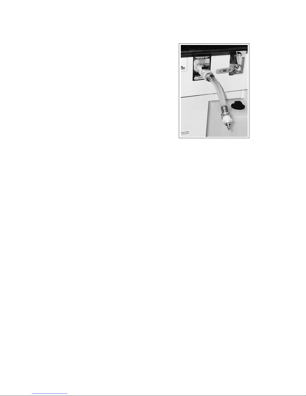
COMMANDER / EMBASSY
12.2.4 TANK RINSE (COMMANDER ONLY)
The motorhome is equipped with a built-in black water waste tank ushing system. To aid in draining the
tank or to remove build-up or odors, attach a water
hose to the ush connection in the utility compartment. Make sure the black tank drain valve is open
when using the water tank rinse system.
12.2.5 DO'S AND DON'TS
HOLDING TANKS
1. DO keep your holding tank clean using any
cleaner approved for recreational vehicle sanitation systems.
2. DO add a special deodorizer or chemical additive approved for recreational vehicle systems to
sanitize and improve the tank action.
Fig. 12-10 FLUSH CONNECTION
(Commander only)
12.2.6 USING ON-SITE SEWER HOOK-UPS
3. DO keep your tank termination valve closed,
permitting the tank to get as full as convenient
before emptying.
4. DO keep both the tank termination valve(s) closed
and the drain cap tightly in place when travelling
to prevent spillage on the road.
5. DO use any soft, single-ply, non dyed, biodegradable toilet tissue.
6. DO open the bath vent to keep bathroom fresh.
7. DON'T put facial tissues, paper, permanent (automotive) anti-freeze, sanitary napkins, or household toilet cleansers in your holding tank.
8. DON'T put anything solid in your holding tank
which can scratch or damage the plastic.
When staying at a campsite for any period of time
where sewer hook-ups are available, the sewer hose
may be attached and left in place for the duration of
the stay.
However, ensure that dump valves are left closed and
are opened only once the tanks are full or when you
leave the campsite. This will keep solid wastes in suspension allowing them to drain with the liquids when
the valves are opened. If the valves are left open, the
liquid wastes will drain leaving the solids to collect on
the oor of the black water holding tank oor.
Should this happen, close the valves, ll the tank with
water and drive a few miles. A 1/4 cup of dishwater
detergent added to the tank will help to clean it. The
motion of the vehicle and the water will dislodge the
wastes and allow the tank to be drained in the normal
manner.
12-8
 Loading...