


A WORD TO MOTORHOME OWNERS
Welcome to the growing number of discerning peo-
Our company takes great pride in the quality and
with respect to safety, convenience, styling, and
We appreciate having you as our customer and
of your new motorhome. Each person using the
stand the many built-in operational features of this
any questions about your unit.
We hope you will enjoy your new motorhome, and
we wish you pleasant and carefree driving.
WARNING
Throughout the manual, certain instructions, pro-
cedures and information is emphasized with the
words IMPORTANT, CAUTION and WARNING.
These key words denote the level of care that each
operator should exercise on mechanical and safety
Failure to read the manual completely and thoroughly may lessen your total enjoyable experience.
Modifi cations that are not approved
by Triple E may void the warranty and
transfer responsibility for the changes
to the owner.
This manual is intended to be a guideline. This manual despite our best efforts
should not be considered comprehensive
in all details. We invite you to use this
manual to help you learn the basics about
your vehicle. The component operation
will be in the manual for the fridge, stove,
IMPORTANT
This vehicle is equipped with the latest
systems, appliances and operational
equipment making it considerably more
complicated than a normal automobile.
The use of three way systems; 120V,
12V and propane needs careful consideration as the availability of energy
in both the 12V and propane systems
has a limited capacity and volume. Due
caution should be applied and in case of
doubt, clarifi cation from the authorized
Triple E dealer or our factory service
department should be obtained. Do not
modify the unit in any way. Unauthorized modifi cation may impair
the function or life of the vehicle and
could lead to an accident.

TABLE OF CONTENTS
..............................................
1.2 Information Kit
................................
1.3 Options and Equipment
1.4 Keys
...............................................
1.5 Vehicle Certifi cation Label
1.6 Identifi cation Information
................
1.7 Exterior Feature Identifi cation
1.8 Service Assistance
...............
1.10 Driving Comfort
2 Safety
.........................................................
2-1
2.1 General Safety
2.2 Driving Safety
.................................
2-2
2.3 Fuel (Motor and LP Gas)
2.4 Asphyxiation
...................................
2-3
2.5 Formaldehyde
2-3
2.6 LP Gas Leaks
2-3
2.7 Alarms
............................................
2-4
2.8 Electrical
2.9 Loose Components
........................
2-5
2.10 Maintenance
2-5
2.11 Emergency Exits
............................
2-5
3 Preparation
3-1
3.1 Vehicle Preparation
........................
3-1
3.1.1 Keys
3-1
3.1.2 Vehicle Loading
3-1
3.1.3 Trailer Towing
................................
3-2
3.1.4 Auxiliary Vehicle Towing
3-2
3.1.5 Parking, Levelling and Blocking
.....
3-3
4 Controls
4.1 Chassis Controls
............................
4-1
4.2 Dash Controls
4.3 Driver's Door (Commander Only)
...
4-4
4.4 Driver's/Co-Pilot Seat
4-5
4.5 Cocktail Seat
4-6
4.6 Seat/Shoulder Belts
.......................
4-6
4.7 Front Upper Cabinets
4-8
4.8 Bedroom TV
...................................
4-9
4.9 Side Entry
4-10
4.10 Refrigerator
..................................
4-11
4.11 Light Switches
4.12 Comfort Control Center
................
4-13
4.13 Furnace
4.14 Thermostatically
Controlled Celing Fan
..................
4-15
4.15 Plumbing
......................................
4-16
4.15.1 Water Heater
4-16
4.15.2 Water Heater Bypass
...................
4-17
4.15.3 Water Pump
4-18
4.15.4 Utility Module
...............................
4-19
4.15.5 Water System Access
(Embassy Only)
...........................
4-21
4.16 TV Antenna
4-23
4.17 Battery Disconnect
4.17.1 Commander
.................................
4-24
4.17.2 Embassy
4.18 Slide-Out Room (Optional)
...........
4-25
4.19 System Monitor
4-26
4.20 Energy Management System
(EMS) - Commander only
5 Driving
.......................................................
5-1
5.1 Pre-Trip Inspection
5-1
5.2 Emergency Equipment Check List
5-2
5.3 Before Departing
............................
5-2
5.4 Engine Operation
5-2
5.5 Driving Characteristics
...................
5-3
5.6 Driving Safety Tip
5-3
5.7 Travel Tips
.....................................
5-4
5.8 Quick Loading Check List
5-5
5.9 Sever Weather Information
............
5-6
6 Safety Equipment Operation
6-1
6.1 Fire Prevention
6-1
6.1.1 Fire Safety Tips
..............................
6-1
6.1.2 Fire Extinguisher
6-2
6.2 Emergency Escape
........................
6-3
6.3 Alarms
6-4
6.3.1 LP Gas Alarm
.................................
6-4
6.3.2 Carbon Monoxide Alarm
6-5
6.3.3 Smoke Alarm
.................................
6-6
6.3.4 Intruder Alarm
(Optional - Commander only)
6-7
6.4 Rear View Camera/Monitor System
....
6-8
7 Travelling
...................................................
7-1
7.1 Preparation
7.2 Baggage Loading
...........................
7-1
7.2.1 Roof Loading
7.2.2 Baggage Compartments
................
7-1
7.3 Vehicle Weight-Loaded
7.4 Front Axle Tire Alignment
7.5 Maximum Occupancy
....................
7-2
7.6 Seat Belts
7-3

TABLE OF CONTENTS
.....................................
11.1 Safe Use of LP Gas
11.2 How LP Gas Works
......................
11.3 Selecting Fuel Types
11.4 LP Tank System
...........................
11.5 LP Tank Capacity
11.6 Refi lling LP Tank
..........................
11.7 Air in the LP Tank
11.8 Travelling LP Gas
11.9 Regulator
.....................................
11.10 LP Gas Leaks
11.11 LP Gas Detector
..........................
12.1 Fresh Water System
....................
12.1.1 Fresh Water Tank Filling
Procedure
....................................
12.1.2 Water Pump
12.1.3 Water Pump Switch
12.1.4 Water Pump
.................................
12.1.5 Water System Access
12.1.6 Water Pump Initial Start-Up
.........
12.1.7 Water Pump Troubleshooting
12.1.8 Disinfection of Water Tank
...........
12.1.9 External Water Supply
12.2 Waste System
..............................
12.2.1 Grey Water - Waste Holding Tank
12.2.2 Black Water - Waste Holding
Tank
.............................................
12.2.3 Dumping Holding Tanks
12.2.4 Tank Rinse
...................................
12.2.5 Do's And Don'ts Holding Tanks
12.2.6 Using On-Site Sewer Hook-Ups
..
12.2.7 Holding Tank Level Indicators
12.2.8 Tank Capacities
.........................
12.3 Plumbing System Operation
12.3.1 Water Heater
12.3.2 Toilet
..........................................
12.3.3 Shower
12.3.4 Exterior Shower (Optional)
.........
12.3.5 Water Purifi er
(Optional - Commander only)
.....
12.4 Plumbing Specifi cations
12.4.1 Tank Capacities
.........................
12.4.2 Plumbing Schematics
13.1 Refrigerator
..................................
13.1.1 Operating Instructions
13.1.2 Operating Tips
.............................
7.6.2 Shoulder/Lap Belts
.........................
7-3
7.6.3 Care and Cleaning
7.6.4 Child Restraints
..............................
7-4
7.7 Mirrors
7.8 Free Standing Dinette
7-5
7.9 Refuelling
.......................................
7-5
8 Emergencys While Driving
8-1
8.1 Hazard Warning Lights
..................
8-1
8.2 Flat Tire
8-1
8.3 Towing
...........................................
8-2
8.4 Overheating
8-2
8.5 Jump Starting
.................................
8-3
9 Home Use
9-1
9.1 Parking
9.2 Motorhome Levelling System
(Optional)
9.3 Slide Out Room (Optional)
.............
9.3.1 Slide Out Room - Powered
9.3.2 Slide Out Room
Emergency Operation
9.4 Slide Out Room Troubleshooting
...
9.5 Central Vacuum System
(Commander only)
9.6 Prolonged Occupancy
....................
10.1 120-Volt AC System
.....................
10.1.1 External Power Cord (Shoreline)
10.1.2 Power Control Center
(Optional - Commander Only)
10.1.3 120-Volt Circuit Breakers
.............
10.1.4 Ground Fault Circuit Interrupter
(GFCI)
10.2 Auxiliary 120-Volt Generator
........
10.2.1 Generator Safety
10.2.2 Generator Operation
....................
10.2.3 Automatic Power Transfer Switch
(Commander only)
.......................
10.2.4 Generator Refuelling
10.3 12-Volt DC System
......................
10.3.1 Automotive Batteries
10.3.2 Auxiliary Batteries
10.3.3 12-Volt Coach Fuses
...................
10.3.4 Battery Maintenance
10.3.5 Battery Condition Meter
.............
10.4 Trailer Wiring Connector
10.5 Electrical Schematics
.................
10.6 Vehicle Fuse Panels

TABLE OF CONTENTS
13.1.3 Exterior Refrigerator
Compartment
13.2 Range And Oven
.........................
13.2.1 Lighting Burners
13.2.2 Safety Tips
...................................
13.2.3 Range Hood
13.2.4 Lighting Oven Pilot
.......................
13.2.5 Operating Oven Control
13.2.6 Shut Down Instructions
13.3 Microwave Oven
..........................
13.4 LP Gas Furnace
13.5 Roof Air Conditioners
...................
13.6 TV Antenna
13.7 Signal Amplifi er
............................
13.8 Dash Television - 120 Volt
13.9 Video Cassette Recorder
.............
13.10 Video Control Center
13.11 Phone And Cable TV Hook-Ups
13.12 AC/DC Inverter
.............................
13.13 Sleeping Facilities
13.14 Fresh Water Toilet
.....................
13.15 Electric Step (Optional)
13.16 Screen Windows
........................
13.17 Coffee Maker (Optional)
13.18 Washer/Dryer Hook-Ups
(Optional - Commander only)
14.1 Exterior
.........................................
14.2 Interior
........................
15.1 Chassis Customer Service
15.2 Engine Access
.............................
15.3 Engine Cooling System
15.4 AC And Oil Coolers
......................
15.5 Tires
...........................................
17.1 Cold Temperature Operation
17.1.1 Chassis
........................................
17.1.2 LP Gas
17.1.3 Furnace
........................................
17.1.4 Waste System
..............................
17.1.5 Fresh Water System
17.2 Cold Temperature Storage
..........
17.2.1 Water System Winterization
17.2.2 De-Winterize Water Systems
.......
17.2.3 Water Purifi er
(Commander only)
.......................
17.2.4 Washer/Dryer
(Commander only)
.......................................

COMMANDER / EMBASSY
trouble-free operation at all times.
All owners/operators should read, understand
and follow all instructions in this the motorhome
auxiliary systems and appliances. A few minutes
spent reading the appropriate manual will pay rich
dividends in providing safe, effi cient and trouble-
free operation. Refer to the Ford or GM Operator's
This manual covers all the systems, controls and
operation unique to this vehicle. Always keep the
vehicle for easy reference. Pass the kit on to new
operators or owners as appropriate for their infor-
to fi nd specifi c information.
stand something, please contact:
Your Triple E dealer or
Triple E Recreational Vehicles
301 Roblin Blvd., Box 1230
Winkler, Manitoba Canada
Tel: (204) 325-4361
An information kit is provided with each vehicle and
features and appliances including:
2. Air Conditioning
3. Generator
4. Furnace
5. General Operation
6. Entertainment System
7. Leveling System
8. Water Heater
The Commander and Embassy product lines are
available in various sizes, models and fl oor plans.
The equipment, accessories and components de-
scribed in this manual may not necessarily apply to
your vehicle. Refer to the material provided in the
to your unit.
your vehicle. Use the charts in this manual but

This label contains vehicle identifi cation and other important reference information. The vehicle certifi ca-
tion label is located on the sidewall to the left of the steering wheel, or on the driver's door. Never remove
or destroy this label.
2. Chassis manufacture date.
3. Month and year of manufacture at Triple E
The (GVWR) Gross Vehicle Weight Rating, is
the maximum permissible weight of this fully
5.
Total permissible weight allowed for the front,
and rear axles (listed in pounds and kilo-
6.
Tires recommended to meet handling, load-
any of the tires, the new tires must meet these
specifi cation.
7.
Wheel rims recommended to meet handling
and safety requirements. When replacing any
of the rims on the vehicle ensure that the new
8.
Infl ation pressures recommended (while cold)
for the tires originally equipped on your vehicle.
These pressure levels must be maintained to
assure proper handling, safety and fuel econo-
Single axle/Dual wheels.
Serial Number:
This is the serial number assigned to the com-
cles.
Vehicle Identifi cation Number (VIN):
This number identifi es the chassis on which
the motorhome is built.
Type:
States the NHTSA designated usage clas-
sifi cation for your motorhome. MPV signifi es a
Lists the Triple E product model number of
your vehicle.
Signifi es the color code number of the decor
curtains, carpet, etc. It also is found in the
wardrobe.
MOTORHOME LABELING DEFINITIONS
COMMANDER / EMBASSY
NOTE
The specifi cations sheet is located in the wardrobe.
Beneath the specifi cation sheet are the exterior
color codes.
All Triple E motorhomes are built according to CSA
and RVIA standards.

COMMANDER / EMBASSY

Take a few minutes to fi ll in this information. It will be a handy reference for you. (Some appliances may
door.
Your Name
______________________________
________________________
_________________________
_______________________
___________________________
____________________________
Address
________________________________
________________________________________
______________________________
Agent Name
__________________________
Policy No.
___________________________
Agent's Phone No.
_____________________
Manufacturer
_________________________
Model
_______________________________
Serial No.
____________________________
Manufacturer
_________________________
Model
_______________________________
Serial No.
____________________________
Video Cassette Player
Manufacturer
_________________________
Model
_______________________________
Serial No.
____________________________
Television
Manufacturer
_________________________
Model
_______________________________
Serial No.
____________________________
Manufacturer
_________________________
Model
_______________________________
Serial No.
____________________________
Water Heater
Manufacturer
_________________________
Model
_______________________________
Serial No.
____________________________
Manufacturer
_________________________
Model
_______________________________
Serial No.
____________________________
Air Conditioner #1
Manufacturer
_________________________
Model
_______________________________
Serial No.
____________________________
Air Conditioner #2
Manufacturer
_________________________
Model
_______________________________
Serial No.
____________________________
Manufacturer
_________________________
Model
_______________________________
Serial No.
____________________________
Key No.
_____________________________
____________________________________
____________________________________
____________________________________
COMMANDER / EMBASSY

2. Refrigerator Service Access.
3. Range Hood Vent.
4. Porch Light.
5. Propane Tank
6. Storage Compartment
7. Entrance Step.
8. Furnace Service Access Panel*.
Includes: Water Drain Valves.
Fresh Water Filler.
Winterization Valve.
Holding Tank Drain Valves.
Black Water Flush System.
COMMANDER / EMBASSY
*
NOTE
Some equipment shown may be
optional.
*
*CAUTION
Be careful. These features may
become hot while water heater or
furnace are in use.

2. Refrigerator Service Access.
3. Range Hood Vent.
4. Porch Light.
5. Storage Compartment.
6. Propane Tank Access
7. Entrance Step.
8. Furnace Service Access Panel*.
Includes: Water Drain Valves.
18
COMMANDER / EMBASSY
NOTE
Some equipment shown may be
optional.
*
*
*CAUTION
Be careful. These features may
become hot while water heater or
furnace are in use.

Your dealer will be glad to provide any additional
you may have about the operation of your mo-
torhome. When it comes time for service, remem-
the period of your ownership. It is advisable that
you follow a regular maintenance schedule to keep
your vehicle functioning at its best.
dealer for help.
DEFECTS
defect of any kind that could cause injury, or death,
contact Triple E immediately. As well, make sure
to contact the National Highway Traffi c Safety
Administration (NHTSA) if you are a resident of the
The NHTSA or Transport Canada will investigate
the concern should there be a number of similar
complaints. They have the authority to order a re-
call and repair campaign depending on the nature
and severity of the problem.
The NHTSA may be reached by using the Auto
Washington, DC area) or by writing to: NHTSA, US
20590. The Hotline will also provide you with ad-
ditional information on motor vehicle safety.
Triple E has made every effort to design and con-
struct your motorhome for your comfort and safety.
We know that your investment is important to you
as well as to us. Our design team has dedicated
comfort and protection packages in the industry.
one of the fi nest motorhomes on the road today:
a. Optional, ducted roof-mounted air condi-
tioning units with up to 13,500 BTU's of
cooling capacity per unit. Available with
the air conditioner is a heat strip to supple-
single 15,000 BTU unit is also available.
b. High output chassis air conditioner for
travelling comfort.
c. Electronic ignition LP gas furnace de-
signed to maintain a comfortable tem-
degrees C (-5 degrees F). However, tem-
d. High output chassis heater for your driving
comfort.
e. Thermally effi cient vacuum-bonded com-
foam insulation for strength and designed
to reduce freeze-through.
f. One piece headliner for warmth and noise
g. Automatic, electronic ignition water heater.
h. Motor-aid (Commander only) water heater
to heat hot water while travelling.
a. Fiberglass (Commander) or FRP (Em-
b. Seamless EPDM rubber roof to ensure a
weather proof seal.
c. Tubular aluminum reinforced walls and
d. Urethane undercoating for protection
against dust and moisture and to provide
e. Fully insulated, heated holding tank com-
winter freeze-up (All Commanders as well
as equipped Embassy). Enclosed to pro-
tect against road damage.
f. Simplifi ed manual water winterization sys-
tem complete with water heater bypass.
g. Ultraviolet stabilized exterior components
to resist fading and deterioration.
h. Exterior screws and fasteners that resist
streaking.
i. Heavy duty mud fl aps for additional protec-
tion against fl ying stones and mud.
COMMANDER / EMBASSY

2-1
The safety glyph identifi es an area that
sengers or a bystander. Always read, understand
and follow the instructions and information in the
safety sign or manual instruction. Do not take
chances with safety. Most accidents can be pre-
vented.
Although this compilation is thorough, we realize
that it does not cover everything. Each person has
the responsibility of following all listed safety items
This word is used to high-
vehicle.
This word is used to high-
that if not followed will result
the vehicle.
This word is used to high-
that if not followed can
as well as cause vehicle
WARNING
2.1 GENERAL SAFETY
vehicle is the operator. It is the operator's
safety and operating instructions in the vehicle,
chassis, appliance and system manuals. Most
accidents can be prevented.
2. A person who has not read and understood
all operating and safety instructions is not
qualifi ed to operate this vehicle. Untrained
or uninformed operators expose themselves,
to possible serious injury or death and property
damage.
3. Do not modify the vehicle in any way. Unau-
thorized modifi cation may impair the function
and/or safety and could affect the life of the
vehicle.
4. All approved driver and passenger seats are
occupied while driving, each must be locked
attached while in an approved seat. When the
vehicle is moving, no one should be using the
5. Always fasten the seat belt low on the torso
and keep it snug to transmit the force from the
whenever possible. Wear the belt snug and
6. Review the location, function and operation of
the escape window with everyone who will be
7. Establish a monthly fi re extinguisher inspec-
tion program to keep the extinguisher in good
condition and fully charged. Inspect the extin-
siderations during the design and manufacturing
of all Triple E Motorhomes. It is the responsibility
of the owner or operator to read, understand and
follow all instructions in the Motorhome, chassis
and appliance or auxiliary system manuals and
safety signs on the vehicle. Specifi c items, pro-
cedures or instructions are identifi ed with the key
words IMPORTANT, CAUTION and WARNING to
words are defi ned as:
COMMANDER / EMBASSY

2-2
2.2 DRIVING SAFETY
to drive this vehicle.
2. Observe all applicable road and driving regula-
tions. Check with local transport authorities if
you have any questions.
3. Inspect the vehicle before driving. Adjust,
condition.
4. Do not make adjustments such as seat posi-
tion, tilt steering wheel etc. while driving.
5. A motorhome is considerably larger and
different handling characteristics. Allow more
space for stopping, turning, passing, parking,
accelerating etc. during operation. The extra
cornering or on rough terrain. Use extra care
snow, sleet, icy surface, hilly terrain, rough
6. Maintain brakes in top condition at all times.
Allow extra distance for stopping. Be extra
vigilant in adverse surface conditions such as
wet, icy, slushy, rough or a soft surface when
applying the brakes. After going through wa-
ter, slush or snow, apply the brakes carefully
and restore uniform operation. Do not operate
vehicle if uneven brake action persists.
2.3 FUEL
fuel tank, or LP gas tank.
2. Extinguish all pilot lights before refuelling.
3. Do not fi ll the LP gas tank or vehicle fuel tank
when the generator is running.
4. Do not bring or store fuel or LP gas contain-
vehicle. Vapours can be released causing
atmosphere.
5. Do not fi ll LP gas containers more than 80%
of capacity. Overfi lling can lead to excessive
venting or gas fl ow and result in an explosion
or fi re.
6. Do not use an open fl ame to check for an LP
7. Do not connect natural gas supply to the LP
system.
8. Install LP gas regulators with the pressure
struct vent hole. In cold weather, condensation
can get into the regulator and cause freeze-up.
open fl ame or heat lamp to thaw out.
Turn burner off and let gas dissipate before
trying to relight if it does not light immediately.
workers to close master valve if an emergency
occurs.
COMMANDER / EMBASSY

2-3
2.4 MINIMIZING
ASPHYXIATION RISK
cause fi res.
2. Provide proper ventilation when using the gas
a. Open overhead vent or turn on exhaust
fan, and…
b. Open window.
3. Avoid breathing the exhaust fumes from a gas
or generator engines and the range, oven,
tion the vehicle so the wind blows the engine
when appliances or furnaces are being used
to prevent a build-up of carbon monoxide. Be
sure all alarms are working.
4. Do not run vehicle or auxiliary generator
5. Use vent or air conditioning fan to force fresh
air into the interior when vehicle is in an open
area with the engine running for more than just
a short time.
6. Maintain engine(s) exhaust system compo-
when exhaust sound changes or when under-
7. Close rear windows when driving to prevent
drawing exhaust fumes into vehicle.
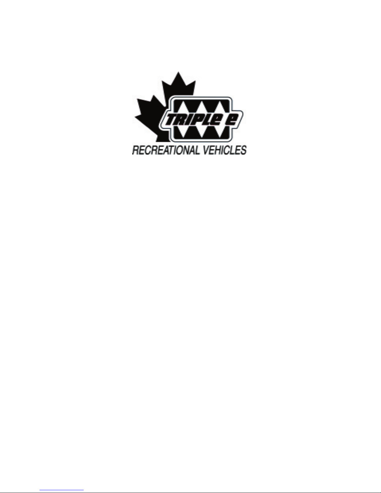
2.5 FORMALDEHYDE FUMES
WARNING
COMMANDER / EMBASSY
components in this vehicle and may release small
amounts of formaldehyde fumes into the vehicle
for an unknown period of time until fully dissipated.
throat. Small infants may have a more serious
serious health effects in humans at the level of
of the formaldehyde fumes by keeping the unit well
ventilated.
to stove:
2. Use soapy water to check for leaks and watch
for bubbles. Do not use an open fl ame.
3. Correct or repair leak(s) before using appli-
ances or vehicle again.
2.6 LP GAS LEAKS
2. Do not touch electrical switches.
3. Shut off the LP tank valve.
4. Open doors, windows and roof vents.
5. Leave the area until the odour is gone.
6. Have the system checked for leaks and make the necessary
corrections and repairs.
WARNING

2-4
2.7 ALARMS
Alarm:
a. Sounds whenever there is an unsafe
amount of gas in the vehicle.
b. Follow instructions on safety sign and air
out vehicle to silence alarm.
c. Have a qualifi ed service personnel fi nd the
a. Sounds whenever there is an unsafe
amount of carbon monoxide gas in the
vehicle.
b. Open doors, vents and windows to air out
vehicle and silence alarm.
c. Have a qualifi ed service personnel check
all burners, clean, repair or replace any
defective burners.
d. Remove all fuel or wood burning devices
from inside vehicle.
e. Have a qualifi ed serviceman check all en-
or replace any defective components. Po-
sition motorhome so wind blows exhaust
fumes away.
3.
Alarm:
a. Sounds whenever there is an unsafe
amount of smoke in the vehicle. Always
b. Open doors, vents and windows to air out
vehicle and silence alarm. Correct and
c. Check alarm on a regular basis. Check
when removing from storage, before trips
and weekly thereafter. Depress center
alarm sensor by blowing smoke (from safe,
fi re-free source) past sensor. If alarm does
of problem and correct or replace alarm.
d. Do not remove battery to silence alarm.
When alarm “beeps” every minute, battery
with recommended battery. Test after bat-
tery is replaced.
e. Clean and vacuum opening on smoke
alarm once a month.
f. Do not try to repair alarm. Replace it.
g. Smoke alarms are not perfect and do not
4. Recurring alarm(s) indicate the slow accumula-
tion of LP gas, carbon monoxide, or smoke.
system and identify source. Correct problem
5. Refer to alarm manual(s) for more detailed
2.8 ELECTRICAL
Wear protective clothing, eye protection and
2. Do not overload electrical circuits. Replace
circuit breakers and fuses with components
of similar capacity. Do not replace with larger
capacity components (breakers or fuses).
3. Be sure motorhome is well grounded to pre-
vent shocks or electrocution. Do not plug utility
which it was not designed.
4. Use care when handling electrical appliances,
or abuse of electrical components can lead to
shocks or electrocution. Do not use electrical
components, cords or appliances with bare
feet, wet hands or while standing in water or on
wet ground.
COMMANDER / EMBASSY

2-5
2.9 LOOSE COMPONENTS
2.10 MAINTENANCE
shorting across starter terminals.
2. Do not remove radiator cap when radiator
or engine is hot. Steam or hot fl uid can be
3. Do not go under a vehicle that is supported
with a jack.
4. Do not mix bias and radial ply tires on the ve-
characteristics. Replace with the same size,
type and load rating.
furniture before transporting.
2. Close, latch or lock all doors, drawers, panels
and gates before travelling.
3. Turn all swivel seats in the forward facing
direction and lock before moving. All passen-
with a seat belt and the seat belt fastened.
4. Stow all cooking, serving, eating and other
component can become a projectile during
sudden stops, manoeuvring or an accident.
2.11 EMERGENCY EXITS
side doors can also be used to exit.
Release the red latches of the emergency
COMMANDER / EMBASSY

3-1
torhome prior to using or driving the unit. Read,
follow the safety tips provided in Section 2. Mo-
torhomes can be used many ways and in many
conditions or circumstances. We have tried to
compile operational and safety instructions to cov-
common sense around the unit and to consult a
dealer if you have any questions.
3.1 VEHICLE PREPARATION
The (CCC) Cargo Carrying Capacity is equal to
The (GCWR) Gross Combination Weight Rating,
facturer as the maximum allowable loaded weight
of this motorhome with its towed trailer or towed
vehicle combined.
To check that your motorhome is properly loaded,
drive the fully loaded vehicle to a scale and weigh
as follows:
a. Drive only the front wheels onto the scale
to obtain the front gross axle weight.
b. Next, place the entire vehicle (both axles)
onto the scale to obtain the gross vehicle
weight.
c. Drive forward till only the rear wheels are
on the scale and obtain the rear gross axle
weight.
total vehicle load. If the gross vehicle weight (b) is
and rear gross axle weights against the front and
are within the required limit.
as low as possible. Lighter items may be stored in
cabinets, closets and drawers. Luggage or similar
cargo inside your RV should be secured to prevent
Take note of this label in all exterior storage com-
3.1.1 KEYS
vehicle and include ignition, side door, baggage
compartment, generator compartment and others
depending upon the features of your unit. Always
the vehicle) for easy reference should you mis-
these numbers will allow them to cut a key to fi t
3.1.2 VEHICLE LOADING
The components of your vehicle are designed to
are listed on the Canadian and U.S. Department of
Transport Sticker located on the driver door panel.
The (GVWR) Gross Vehicle Weight Rating, is the
The (UVW) Unloaded Vehicle Weight means the
weight of the motorhome as manufactured at the
factory with full fuel, engine oil and coolants. The
The (SCWR) Sleeping Capacity Weight Rating is
the manufacturer's designated number of sleeping
COMMANDER / EMBASSY
CAUTION
Baggage Compartments Are Not To Be
Loaded In Excess of 75 kgs./165 lbs.
Total Vehicle Load Not to Exceed The
Maximum GVWR/GAWR/GCWR Of The
Chassis.

3-2
3.1.3 TRAILER TOWING
A trailer can affect the handling, durability,
torhome. The factory installed towing hitch
a. 500 lb. - maximum hitch or
tongue weight.
b. 5000 lb. - maximum trailer weight.
The combined weight of the motorhome
and the towed vehicle should not ex-
ceed the Gross Combined Weight Rating
the motorhome and the tongue weight of
the towed vehicle should not exceed the
To be sure of the correct balance in weight, it is ad-
vised that you take your loaded vehicle to a weigh-
scale to determine the actual weight distribution.
After you have done this once, you will have a
change. Make sure your trailer is equipped and
connected to your motorhome with the proper
control vehicle speed. Avoid prolonged or frequent
application of brakes if at all possible to prevent
overheating and possible failure of the braking
your motorhome, your Triple Edealer will provide
you with the information, advice and direction you
will require.
3.1.4 AUXILIARY VEHICLE TOWING
The total weight of the motorhome and the vehi-
cle towed must not exceed the GCWR rating as
stated on the Vehicle Certifi cation label.
COMMANDER / EMBASSY
CAUTION
Exceeding any of the recommended
gross vehicle weight ratings may result
in vehicle damage.
WARNING
Do not install a weight equalizing type
of hitch on your motorhome.

3-3
3.1.5 PARKING, LEVELLING AND BLOCKING
Try to pick a spot as level as possible on which to
or back in depending on your personal preference.
tions (water, sewer, electrical, etc.) are all located
on the left side of your motorhome.
for your own comfort but for the proper functioning
of your appliances such as your refrigerator. The
vapor cooling system can “lock up” and damage
the refrigerator if it is not level. As well, the vari-
ous water and waste levels in the different hold-
torhome Levelling in Section 9.2 of this manual to
torhome to bring it to level. After your motorhome
front or behind the wheels in order to prevent your
you block both tires so that the load is not carried
Always exercise care and caution when park-
everyone, especially children, are well clear until
the vehicle has been stabilized and parked with
the ignition off.
the ignition off.
COMMANDER / EMBASSY
WARNING

4-1
and settings of all controls. Each new person should be trained in all aspects of motorhome operation
4.1 CHASSIS CONTROLS
standard automotive, steering column, transmission and instrument cluster controls, lights and gauges.
COMMANDER / EMBASSY

4-2
COMMANDER / EMBASSY
4.2 DASH CONTROLS
a.
AM/FM CD Deck:
This is a standard AM/FM
compact disc deck. Refer to the
decks manufacturers manual
sette deck is also available.
b.
This is the standard climate con-
trol used for all Class A Triple E
and includes both the heating
and cooling functions for the
driving section of the vehicle.
c.
only):
This push button switch controls
the power to the coach (on a
cabinet) foot lights. Depress the
turn the foot lights on. Depress
the top portion to turn them off.
g.
This push button switch controls the power
to the exterior rear view mirror heaters.
turn the heaters on and the top portion to
turn off. The heater will automatically be
shut off when the ignition switch is turned
off. The heater will also shut off once it
2.
a.
This spring loaded push button switch con-
trols the interconnect circuit between the
auxiliary and chassis batteries. Depress
and hold the switch to connect the auxiliary
the switch to disconnect. Use this inter-
connect only when the chassis batteries
are too run down to start the engine.
b.
and Embassy XL only):
This push button controls the power to the
tom portion of the switch to turn the fan 2
speed switch on and the top portion to turn
off.
c.
This push button switch controls the power
to the fans mounted on the bottom of the
overhead cabinet. Depress the bottom
the top portion of the switch to turn off.
d.
Stereo:
This push button switch controls the power
to the stereo. Depress the bottom portion
of the switch to turn on the power from the
coach battery. Depress the switch again
to turn it off. Unit also has a switch in the
stereo without turning on the ignition.
e.
This push button switch controls the power
to the lights on the bottom of the overhead
cabinet above the dash used to illuminate
a map. Depress the bottom portion of the
switch to turn the map light on and the top
to turn it off.
f.
Auxiliary Generator Control (Optional):
This 3 position push button switch controls
the operation of the auxiliary generator.
against the spring to engage the starter
to the auxiliary generator. Release the
switch when the generator engine starts.
d
c
fg
b
a

4-3
d.
er only:
This cluster of switches controls
the position of the rear view
center switch to select the left or
the four outer switches as re-
quired to move the mirror to the
desired position.
e.
This 3 position rotary switch
controls the power to the vehicle
terclockwise to turn off. Turn
clockwise to the fi rst detent for
the parking and panel lights.
Turn fully clockwise to turn the
This rotary switch controls the
the power and turn the lights
off. Roll down to increase power
g.
Jacks Down Light (Optional In-
cluded With Levelling System):
This red light indicator alerts the
driver that the levelling jacks are
on when the ignition switch is
switched on and the jacks are
down.
This meter displays the generator
operating hours and accumulates
time whenever the generator is
3.
a.
System:
This panel contains the controls
for the computerized hydrau-
structions.
IMPORTANT
The headlights come on at partial
power whenever the engine is running. The switch must be turned on
for the headlights to operate at full
power.
COMMANDER / EMBASSY

This rocker switch sets the position of the drivers
door window. Depress and hold the foward portion
of the switch to raise the window and back portion
to lower.
4-4
4.
a.
tional Commander Only):
This push button switch con-
trols the valet feature of the
b.
This port is located under the
chassis owner's manual in the
details.
COMMANDER / EMBASSY
4.3 DRIVERS DOOR - Commander only
a
b

4-5
COMMANDER / EMBASSY
4.4 DRIVERS/CO-PILOT SEAT
oth the drivers and co-
pilot seats are designed with a sliding base to
allow the seat to be moved forward or
fort.
a.
A spring loaded latch is located at the end of the
the seat as desired and lock it in position.
b.
The spring loaded latch is located on the front
2.
Both the drivers and co-pilot seats
are designed with a swivel base to allow the seat to
a.
A spring loaded latch is located at the end of
the right hand arm rest to release the swivel
turned in the direction of travel, the swivel lock
will automatically engage and secure the seat.
co-pilots seats are locked in the forward facing
direction. One some fl oorplans the seat may
to rotate it.
b.
The spring loaded latch is located at the right
side underneath the seat. Push the lever back
to release the lock. Swivel the seat as desired.
When the seat is turned in the direction of
travel, the swivel lock will automatically engage
and secure the seat. Do not move the vehicle
3.
This spring loaded lever controls the lock on the
2
1
3
3
1
2
4-6
COMMANDER / EMBASSY
4.6 SEAT/SHOULDER BELTS
when travelling. Every occupant must be seated in one of the approved seats with the belt fastened whenev-
occupants not seated in an approved seat and restrained with a seat belt risk injuries of a more serious nature
than those properly restrained.
The driver and co-pilot seats are equipped with a combination lap and shoulder belt for maximum restraint
a. Sit in the seat and rotate the seat until it is facing
forward and the latch locks.
b. Pull the spade end of seat belt across the body and
to indicate that the spade is locked securely in
c. Be sure the belt is not twisted to minimize load
concentrations during impact. A fl at belt distrib-
d. Slide the lap portion of the safety belt system low
on the torso to distribute the load across the hip/pel-
vis area.
e. Slide the shoulder strap so it lays diagonally across
the chest and shoulder area. Do not lay it against
the neck.
f. Depress the button on the buckle to release the belt
assembly. Hold the belt as it is released to prevent
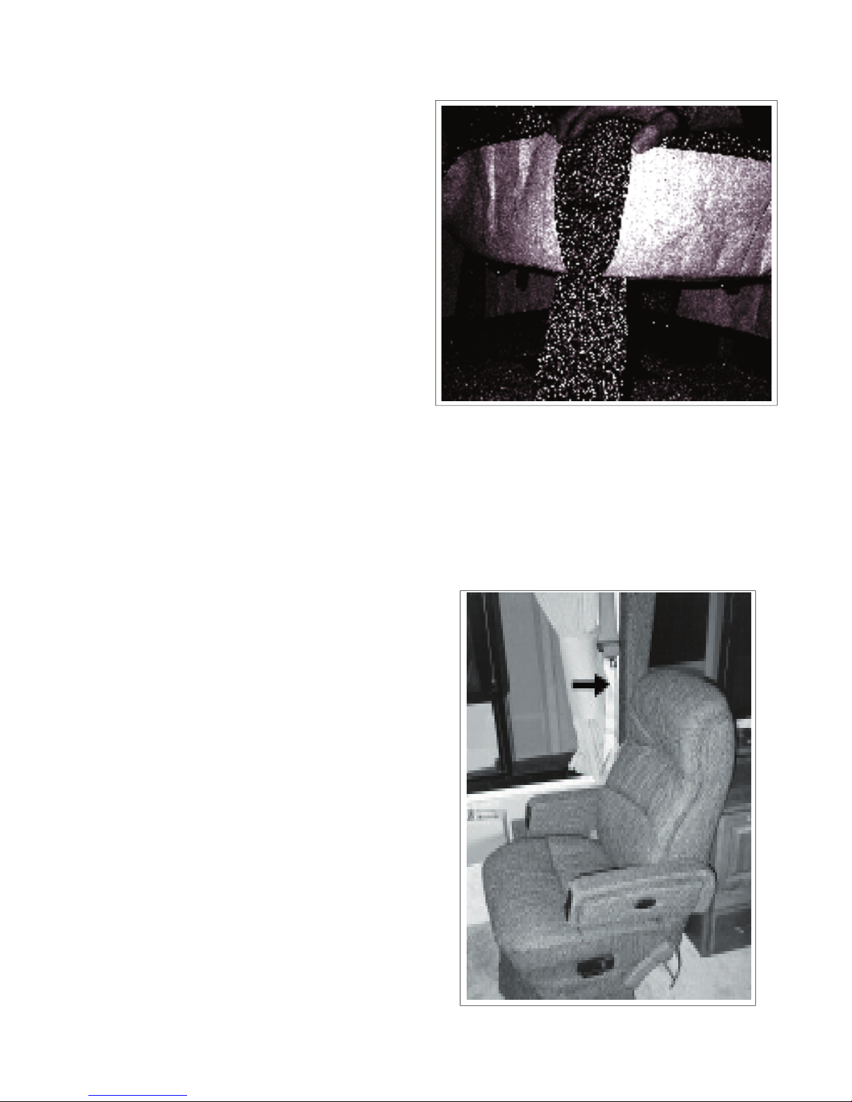
4.5 COCKTAIL SEAT
A cocktail chair is located behind the co-pilots seat and is
This latch releases the swivel base. Push the latch to
the seat returns to this position, the lock will again
This Spring-loaded latch releases the lock on the
sliding base to allow the seat to be moved forward
or backward and is located under the seat. Push on
the latch to release the lock and slide the seat to its
desired position. Release the latch to lock the seat in
1
2
IMPORTANT
All seat belt retractors are equipped with locks
that engage when the belt moves too fast.
Move the spade end slowly and steadily when
fastening to prevent locking. If belt locks
while fastening, release end and let it retract
fully. Then pull again to fasten.

4-7
Only seats equipped with seat belts
are approved for use by occupants
while the vehicle is moving. Never
travel in a seat that is not equipped
with a lap or shoulder belt.
a. Sit in the seat and rotate the
chair to its locked position.
b. Pull the spade end of the seat
the spade is locked securely in
c. Be sure the belt is not twisted
to minimize load concentrations
during impact. A fl at belt distrib-
area of the body to reduce the
chance of injury.
d. Slide the strap low on the torso
and touching the top of the
thighs to distribute the impact
COMMANDER / EMBASSY
b. Make sure the system will attach to your
vehicle conveniently and provide safety for
your child every time it is used.
c. Be sure the restraint system is suitable
and adequate for your child's age, weight
and height. Check the label for this infor-
d. Review the instructions supplied with the
child restraint system. Be sure that any-
one placing a child restraint system in a
vehicle fully understands how it must be
e. Depress the button on the buckle to
the belt as it is released to prevent it from
3.
Pregnant women should wear their lap belts
agonally across their chests. Do not position
the strap against the neck. Wearing a seat or
shoulder/lap belt properly will protect both the
4.
Child restraint systems are a legal require-
a certifi ed child restraint system experience
those properly restrained. In order to provide
the safest restraint system for your child during
transport, follow these considerations when
selecting an appropriate child restraint system:
a. Purchase a child restraint system that is

4-8
4.7 FRONT UPPER CABINETS
A.
VCR (Optional):
This is a standard VCR and is a part of the
vehicle entertainment system. Refer to the
details. Close the cabinet door when VCR
access is not required.
B.
An input channel selector is located on top
of the VCR and is used to select a specifi c
signal to each TV in the vehicle or the
VCR.
TV1
a.
ANT:
This push button switch selects the
b.
AUX:
This push button switch selects the
auxiliary signal, normally cable, as the
source of the input signal to TV 1 or
the one mounted in the front console.
c.
VCR:
This push button switch selects the
VCR output as the source of the input
signal to TV 1 or the one mounted in
the front console.
COMMANDER / EMBASSY
VCR
a.
ANT:
This push button switch selects the
antenna signal and directs it into the
VCR.
b.
AUX:
This push button switch selects the
auxiliary signal, normally the external
cable input, and directs it into the VCR.
TV2
a.
ANT:
This push button switch selects the
b.
AUX:
This push button switch selects the
auxiliary signal, normally cable, as
the source of the input cable to TV-2
c.
VCR:
This push button switch selects the
VCR output as the source of the input
signal to TV 2(bedroom).
B
A

4-9
4.8 BEDROOM TV - (OPTIONAL, N/A Embassy A-27)
A motorhome can be equipped with a
TV in the bedroom. Although it func-
tions like a standard TV, it is recom-
the input selector to select the signal
source.
COMMANDER / EMBASSY
3.
A vehicle can be equipped with a rear
view camera and monitor to provide the
driver with a way to see behind the mo-
torhome when backing up or viewing a
trailer or car in tow. The monitor operates
similar to that of a TV monitor. Review
the booklet in the information package for
detailed operating instructions.
Rear view camera option available on the

4-10
COMMANDER / EMBASSY
4.9 SIDE ENTRY
The side entry doorway left wall is
controls the following functions:
This 2 position rocker switch
controls the power to the outside
tion for off.
This 2 position rocker switch con-
trols the power to the side entry
step. Depress the upper portion of
the switch to turn the step mecha-
tion for off. The step will extend
when the door is opened
and retract when the door is closed. Refer
to the Step System Operator's Manual in the
tions on step extension when occupied, “last
out” feature and retraction for driving.
3.
This 2 position rocker switch controls the
power to a coach interior light. Depress the
and the lower portion for off. The switch on the
This 2 position rocker switch controls the
compartments. Depress the upper portion of
the switch to turn the power to the lights on
and the lower portion to turn off. This mas-
ter switch must be on before any of the light
switches in any exterior compartment will work.
2
3
4
4-11
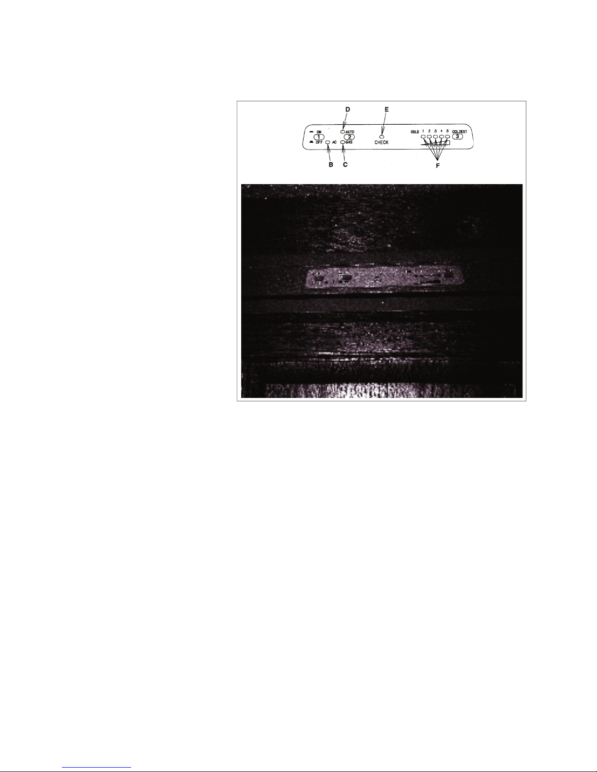
4.10 REFRIGERATOR
The refrigerator control panel is
tor lights.
This latching push button switch
controls the power to the refrig-
will latch in the depressed posi-
tion for the power to be on. De-
switch will be in its up position.
2.
This push button switch selects
which power source will be used
to operate the refrigerator. De-
the AUTO mode and the AUTO
IMPORTANT
a. If 120 volt power is available, the AC
circuit will operate the refrigerator.
b. If 120 volt power is not available, the GAS
and the LP gas system will provide power to the
on. Refer to IMPORTANT above if the CHECK
3.
Temperature Switch:
This push button selector switch sets the
desired refrigerator operating temperature
during operation. Depress the switch once to
setting. The indicator lights (F) will illuminate
as the selector switch is depressed to identify
the operating temperature selected. Set at
the coldest setting for the fi rst couple of hours
of operation to cool everything down and then
select the mid-range setting.
The control panel operates
on 12 volt DC power. This
requires the coach batteries to be at full charge for
proper control.
COMMANDER / EMBASSY
IMPORTANT
If the CHECK indicator light
comes on and the GAS indicator
light doesn't come on, the burner
has failed to ignite, turn the system off and then on again to light
the burner.
IMPORTANT
When running the fridge on LP
gas, ensure the shut off value on
the LP tanks are open.

4-12
Wall
4.11 LIGHT SWITCHES
switches are used throughout the
switch and light work together, try the
switch.
COMMANDER / EMBASSY

4-13
4.12 COMFORT CONTROL CENTER
A comfort control center is located in the motorhome (living
area or bedroom) to control the heating and cooling systems
fi cations of your vehicle and will control one or more furnaces
and air conditioners.
detailed operating instructions. The control functions include:
This liquid crystal display shows the operator the specifi c
operating parameters of the comfort appliances. The dis-
2.
This push button switch controls the selection of the
system operating mode. Depress the switch momentarily
to step the fan, cool, furnace and heat strip. Depress the
switch again momentarily to move to the next selection.
The mode selected will show in the Liquid Crystal Dis-
3.
This push button switch controls the settings for fan
speed and mode. Depress the switch momentarily to
step the fan through each setting from low, medium, high
and auto. Depress the switch again momentarily to move
to the next setting. The speed selection will show in the
Temperature Selector Buttons (Up and Down) (D):
These push buttons raise or lower the selected system
temperature. Depress the switch momentarily to change
the temperature. Continue to momentarily depress the
switch to change the desired temperate. The selected
temperature will show in the Liquid Crystal Display.
5.
Zone and Stage Selector Buttons (E):
These push buttons select the individual zones and
stages for the system. Depress both buttons simultane-
ously in a momentary manner to step the control system
through its choice of zones and stages. Zones refer to
air conditioner cooling areas and stages refer to heating
areas. The selected zones and stages will show in the
Triple E Motorhomes.
6.
This sliding lever switch is the master ON/OFF switch for
the comfort system. Move the lever to the left to turn off
A. Liquid Crystal Display
Schematic
COMMANDER / EMBASSY

4-14
4.13 FURNACE
one or two furnaces depending on the
confi guration. They are controlled by
the comfort control center. Review the
operator's manuals for the furnace and
comfort control centre in the information
and contact can cause serious burns.
COMMANDER / EMBASSY
WARNING

4-15
4.14 THERMOSTATICALLY CONTROLLED CEILING FAN
(Optional on Embassy)
vide a controlled air fl ow through the
vehicle. Use the vent fan in conjunc-
tions with an open window to provide
a fl ow of fresh air into the unit.
This rocker switch controls the
the vent. Depress the IN side of
the switch for the fan to draw air
side for the fan to blow air out.
The fan must always come to a
complete stop when changing
directions.
2.
This 4 position rotary switch
controls the power to the fan and
the fan speed. Turn the switch to
tion to turn the fan off. Turn the
switch to its fi rst, second or third
clockwise detents (Position 1, 2
and 3 respectively) to set the fan
speeds at low, medium or high.
The roof vent must be open at
safety switch will prevent the fan
from coming on.
3.
Vent Height:
This knob controls the position
of the vent hood. Turn the knob
clockwise to pull the hood down
and close it. Turn counterclock-
wise to raise or open the hood.
4.
Thermostat:
This rotary switch controls the set point for
the system thermistat. Turn the knob to the
desired position. Moving the pointer to the red
ture of the set point for the vent fan to come
on. To operate, the vent must be open and fan
switch turned to either in or out.
COMMANDER / EMBASSY
3

4-16
4.15 PLUMBING
A motorhome plumbing system consists of fresh,
and plumbing. Be sure to review, understand
and follow all operating instructions for the sys-
4.15.1 WATER HEATER
The water heater is located next to an outside
wall and is only accessible from the outside. All
water heaters are designed to operate using ei-
ther LP gas, motor aid (Commander only) or 120
volt electric power. Both electric and gas power
sources require water in the tank before starting
to heat water or the element or tank will burn out.
To select electric power:
the vehicle. (Fig 4-20)
exhaust vent. These components are ex-
tremely hot and contact can cause serious
2. Remove the click pin lock through the rocker
switch. (Fig. 4-21)
3. Depress the on portion of the switch to turn
the power on to the electric heating ele-
4. Refer to operator's manual in information pack-
age for more detailed operating instructions.
To Select LP gas only:
2. Secure with click pin
3. Turn the water heater switch on, located on
the moniter panel.
The motor aid feature will automatically heat the
water in the tank when the engine is running.
COMMANDER / EMBASSY
2. Do not touch electrical switches.
3. Shut off the LP tank valve.
4. Open doors, windows and roof vents.
5. Leave the area until the odour is gone.
6. Have the system checked for leaks and make the neces-
sary corrections and repairs.
IMPORTANT
The electric water heating system
will operate when turned on only
when there is suffi cient 120 volt
AC power available. If there is no
or insuffi cient power, the system
will revert back to gas to heat the
water.
WARNING
WARNING

4-17
4.15.2 WATER HEATER BYPASS
The water heater is equipped with
a valve that sets its plumbing circuit
for normal or winterize. The valve
torhome by opening the bottom cab-
on your specifi c confi guration.
Watch the pointer on the pivot to
determine the valve setting.
2.
winterizing procedure.
2. Bypass
COMMANDER / EMBASSY

4-18
4.15.3 WATER PUMP
The water system is equipped with a 12 volt
ter to where it is required. A master switch is lo-
cated above the coach doorway to turn the pump
on or off as desired. In addition, the Commander
turned off whenever leaving the motorhome for
any period of time or while driving. A slow leak in
a faucet or connection could drain both the water
tank and the battery.
This switch is located on the master control
this master switch is on. This switch must be
turned on for any of the other auxiliary switch-
(Varies by model, Commander Only):
3.
Water Intake
COMMANDER / EMBASSY

4-19
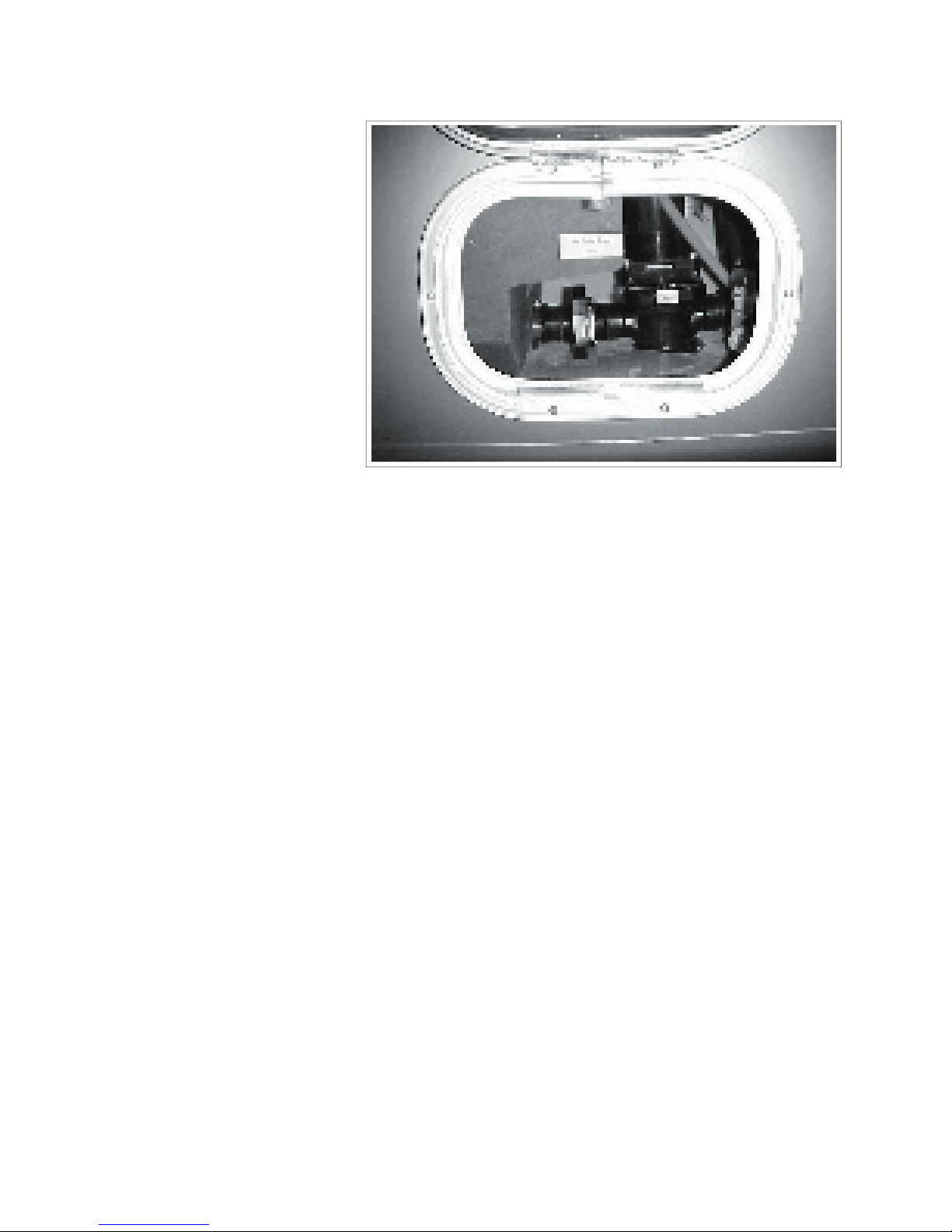
4.15.4 UTILITY MODULE (COMMANDER ONLY)
Access the water system compartment through the door on the left side of the vehicle. Review the oper-
ating instructions and control functions before trying to use the system.
a.
This standard water
tap controls the fl ow
of hot water to the
shower head. Turn
clockwise to turn off
and counterclock-
wise to turn on.
b.
ter:
This standard water
tap controls the fl ow
of cold water to the
shower head. Turn
clockwise to turn off
and counterclock-
c.
This standard fl exible hose shower system
to use it. Turn the collar on the head to
change the spray pattern.
2.
Water Fill Selector Valve:
This valve directs the fl ow of fresh water
the water system and bypass the tank.
Turn counterclockwise when fi lling the
tank and clockwise to bypass the tank and
3.
Water Pump Switch:
This switch controls the power to the water
4.
Water Line Fitting:
This fi tting and cap is the water input fi t-
ting. Always install cover when water line
COMMANDER / EMBASSY
2
3
IMPORTANT
Always use pressure regulator
between the outside water supply
and the motorhome to eliminate
pressure surges and spikes.

4-20
COMMANDER / EMBASSY
5.
This fi tting directs water
directly into the black water
tank and can be used to
quired. Be sure the sewer
valve (black water tank
valve) is open before the
water is turned on.
6.
Water System Winterizing
Valve:
This diverter valve is used
when the water system is
zontal position for normal
operation and vertical when
winterizing the system.
detailed instructions.
7.
This line is used to draw
water system. Normally
8.
Water System Pump
The pump for the water
system is mounted in the
compartment behind this
This fi tting carries the discharge from the
the discharge line to the fi tting and route
tem. Use the opening in the bottom of the
compartment when routing the discharge
when discharging. Install dust cap when
the discharge hose is removed.
a.
This is the discharge valve for the black
water tank. Pull out to open valve and
ter tank fi rst and use the gray water tank to
fl ush out any solids which the sewer hose
b.
This is the discharge valve for the grey wa-
ter tank. Pull out to open valve and push
fi rst and then the grey water. This proce-
dure will use the grey water to fl ush out
any solids left in the tank discharge plumb-
5
7
6
7
a
10
b
9

4-21
COMMANDER / EMBASSY
4.15.5 WATER SYSTEM (EMBASSY ONLY)
Access the water system compartment through the door on the right side of the vehicle. Review the oper-
ating instructions and control functions before trying to use the system.
(optional) (Fig 4-27):
a.
This water tap con-
trols the fl ow of hot
water to the shower
to turn off and coun-
terclockwise to turn
on.
b.
This standard water
tap controls the fl ow
of cold water to the
shower head. Turn
clockwise to turn off
and counterclockwise
to turn on.
c.
This standard fl exible hose shower
system is mounted on the front of the
compartment. Turn the handle and lift
the head to use it. Turn the collar on the
d.
Water Pump switch:
This switch controls the power to the
water pump. See section 4.15.3 Water
2. a.
Water Fill Selector Valve:
This valve directs the fl ow of fresh water
the water system and bypass the tank.
Turn counterclockwise when fi lling the
tank and clockwise to bypass the tank
and plumb directly into the water system.
b.
Water Line Fitting:
This fi tting and cap is the water input
fi tting. Always install cover when water
c
a
b
IMPORTANT
Always use pressure regulator
between the outside water supply
and the motorhome to eliminate
pressure surges and spikes.
a
2
b
4-22
COMMANDER / EMBASSY
3.
charge Valves:
a.
This is the discharge
valve for the black water
tank. Pull out to open
valve and push in to
close. Always empty
fl ush out any solids which
the sewer hose left in.
b.
This is the discharge
valve for the grey water
tank. Pull out to open
valve and push in to
close. Always empty
then the grey water. This
any solids left in the tank
discharge plumbing and
3
b
a

4-23
4.16 TV ANTENNA
TV antenna on top of the unit to provide reception
at remote locations. Always fully retract antenna
whenever vehicle is moved or transported.
This crank controls the position of the an-
tenna assembly on top of the roof. Turn
the crank clockwise to raise the antenna
and counterclockwise to lower. Always fully
The antenna can be rotated to align with the
signal to provide the best reception. Grasp
the crank handle mounting plate on both
sides and pull down. Rotate the plate (anten-
TV reception. Always watch the reception on
a TV to know when the reception is the best.
Always rotate the antenna back to its storage
the reference mark before lowering it.
Antenna - Up
COMMANDER / EMBASSY
the antenna, roof, or roof top equipment.
WARNING

4-24
COMMANDER / EMBASSY
4.17 BATTERY DISCONNECT
4.17.1 COMMANDER
This switch disconnects the coach batteries
from the electrical system when the motorhome
switch to disconnect the battery for storage to
4.17.2 EMBASSY
This key switch located under the hood discon-
system to prevent battery discharge when the
Turn the key counterclockwise to turn off and
clockwise to turn on.

4-25
COMMANDER / EMBASSY
This panel controls the operation of the
slide-out room in the motorhome. Review
the extend/retract procedure before operat-
a.
This key switch controls the power to
the pump that supplies pressurized oil
to the hydraulic cylinders that extend
and retract the room. Always turn the
switch off unless moving the slide-out
operation.
This spring-loaded to center neutral
and direction of the slide-out room.
switch to extend the room. Depress and
stop moving.
2.
Slide-Out Room Locks:
This slide-out room assembly is designed
with locks that hold it securely in place for
transport. Embassy: located at the ceiling of
the room on each end, Commander: located
on the fl oor. Turn clockwise to secure lock
and counterclockwise to release. Always
4.18 SLIDE-OUT ROOM (SLIDE-OUT EQUIPPED MODELS ONLY)
curely before moving the motorhome.
WARNING
a
b
CAUTION
Extend levelling jacks on to a fi rm
supporting base and level unit
before extending room.
IMPORTANT
Release the switch when the extend/
retract cylinders reach the end of their
stroke. The pressure of the hydraulic
circuit will change when the cylinders
reach the end of their strokes and the
pump sound will change. Release the
switch when the sound changes.
NOTE
Refer to section 9.3 for detailed
operating instructions.

4-26
4.19 SYSTEM MONITOR
A system monitor is located on the wall next to the doorway.
Five LED's are used to indicate
the status of the tanks and bat-
tery. The tank scale registers
The battery charge condition reg-
and
the battery or tank switches are
depressed.
2.
Each system is equipped with a
switch to activate its own monitor-
switch. The system condition will
a.
b.
c.
d.
3.
Water Pump Master:
This rocker switch controls the power to the
water pump. Depress the top portion of the
switch to turn the power to the pump on. A red
to turn off and the light will go off. When the
can be used to turn the pump on and off (Com-
4.
This 3 position rocker switch controls the
a.
Depress the top portion of the switch
against the spring load to engage the
starter and start the engine. Release the
switch when the engine starts and it will
b.
Depress the bottom portion of the switch
and hold until the generator stops. Re-
5.
Water Heater:
This rocker switch controls the electrical power
to the water heater igniter. Depress the top
the burner ignites.
The red light will remain on if the burner fails to
COMMANDER / EMBASSY
2
d
bec
a
3
4 5

4-27
COMMANDER / EMBASSY
4.20 ENERGY MANAGEMENT SYSTEM (EMS) OPTION AVAILABLE
- COMMANDER ONLY
30 Amp EMS Breaker Panel
This system prioritizes and distributes the power
from the shoreline or generator to the appliances
or other 120 V users. This system disconnects
selected “postpone-able” power draws to elimi-
The selected power draws are automatically
turned back on when the higher priority power
The control box is located on the panel above
the coach entry doorway and the monitoring
the air conditioner, washer/dryer and electric
water heater. Each will be shut down as other
demands increase. Refer to the booklet in the
50 Amp EMS Breaker Panel
The 50-amp service allows you to run more
same time, without tripping the circuit breakers.
50 Amp
30 Amp
IMPORTANT
You will fi nd that not all campgrounds
are equipped with 50-amp service. In
that case, you will need an adapter
plug to connect to the standard 30amp service.

5-1
Always review the chassis manual before starting or moving your motorhome.
5.1 PRE-TRIP INSPECTION
travel.
2. Inspect wheel lugs for tightness. Examine all
tires for road damage. Ensure that all tires are
of Transport sticker located on the drivers door
the left of the drivers seat(Embassy)).
3.
a. Engine/Crankcase Oil
b. Transmission Fluid
c. Power Steering Fluid
d. Radiator Recovery System
e. Reservoir Level
f. Battery Electrolyte Level
g. Windshield Washer Reservoir
4. Check oil level in generator power plant (if in-
stalled). Refer to Instruction and Maintenance
turer for other pre-use requirements.
5. Consult Chassis Manual for recommended list
of system checks.
6. Check to see that all lights are in working or-
der.
7. Check the engine compartment for animals.
Animals and pets like the warmth of the engine
compartment but make a real mess if caught in
the belts.
8. Sanitize and fi ll fresh water tank if required.
Turn off the water pump. (Unless water is
turned off when leaving the unit for any length
of time.
fi ll. An overfi lled LP gas container will cause
the gas regulator to fail, and may result in
stored and all external compartments are
closed and/or locked.
all loose objects secured (including refrigerator
contents).
and/or stowed.
there is proper clearance between adjacent
objects to prevent contact.
All pilot lights and appliances shall be turned off
during refuelling of motor fuel tanks and/or pro-
COMMANDER / EMBASSY
WARNING

5-2
5.2 EMERGENCY EQUIPMENT
CHECK LIST
amount of emergency or safety equipment. Take
2. Emergency Flares
3. Tool Box and Tools
4. Plastic Bucket
5. Tow Rope or Chain
6. Wheel Blocks or Jacks
7. Water Hose
8. Electrical Cord Extension (100-150 ft./minimum
3 wire/30 amp)
5.3 BEFORE DEPARTING
step retract system is turned on to retract step
when side door is closed.
2. Check that TV antenna is retracted, stowed
and secured.
3. Check that room extension is fully retracted
and travel locks are in place if so equipped.
4. Fully retract and lock vehicle levelling jacks (if
so equipped).
5. Secure all objects in vehicle. Tie, latch or lock
all loose objects as appropriate. Unsecured
objects can become a dangerous projectile in
a sudden manoeuvre or accident.
6. Securely close and lock all doors to prevent
coming open in an accident.
7. Lock the driver and passenger seats in the
forward facing direction.
8. Adjust the rearview mirrors to provide the best
to pedal spacing for your personal comfort.
they are snug. All passengers should be in a
seat that is equipped with a seat belt. All preg-
shoulder strap for maximum safety.
a car seat facing rearward.
a seat equipped with a seat belt and the belt is
fastened.
5.4 ENGINE OPERATION
COMMANDER / EMBASSY

5-3
The motorhome driver controls are automotive
type and the steering and braking controls are
fortable as possible. However it must be re-
wider and heavier than a family automobile.
2.
The motorhome power-to-weight ratio is lower
than that of the average automobile. Therefore
tion when moving into traffi c or when pass-
a corner and to change lanes. When going
sure you have suffi cient clearance. Although
you should check your vehicle spec. sheets, if
you have any questions measure the unit. Do
clearance.
3.
When driving in hilly or mountainous terrain
you should employ different driving techniques
than those used when driving under normal,
fl at conditions.
a.
The transmission is designed to down-
shift automatically when required during
a longer uphill climb. If you fi nd that the
transmission shifts up and down rather
frequently, it is a good idea to select a
5.6 DRIVING SAFETY TIP
stand to the rear on the driver's side to guide
you.
2. Before departing on the trip, check your routes.
with LP gas systems.
3. While travelling,
all occupants use
their seatbelts.
4. While travelling,
all doors are
closed and locked and that cabinets, drawers,
and loose objects are secure.
5. Instruct your family on what to do in case of
fi re, and hold fi re drills periodically.
6. Maintain proper charge in the fi re extinguisher.
7. Gas and smoke detectors should not be ob-
structed and should be in working order at all
times. Check battery every month.
8. Keep a well stocked fi rst aid kit handy.
travelling. Pay special attention to inside rear
duals. Make it a habit to check tire pressures
b.
It is a good idea to select a lower gear
on your transmission when descending
a hill to avoid prolonged application of
the brakes. Extended application of the
tear and overheating.
Under extreme conditions this could cause
you to lose control of the vehicle.
5.5
COMMANDER / EMBASSY
CAUTION
Observe the engine temperature carefully especially
during long climbs. If you
notice over-heating, pull off
the road and allow the engine to cool off thoroughly
before you continue. Fill
the recovery tank with coolant if necessary.

5-4
5.7 TRAVEL TIPS
As you travel with your motorhome you will learn much from your own experiences. Share with other mo-
torhome owners and learn from them. Read RV, outdoor and camping magazines for camping and travel
tips. Here are a few basic suggestions to make your travel and your camping easier and more enjoyable:
2. Always fi ll your water tank with clean, fresh,
the tank. It may leave a taste of rubber or
vinyl.
3. Conserve water especially when showering.
The holding tanks have a limited capacity.
4. Dump sewage only at approved dumping sites.
5. Store all liquids in plastic containers with tight
seals.
6. Watch the levels in your holding tanks. Dump
add water to the black water tank to prevent
solids from settling in the tank. Without ad-
can be diffi cult, if not impossible.
7. Sleeping bags are a good idea. They take up
they save on laundry while travelling.
8. Make sure all compartment doors and refrig-
Open these doors carefully after travelling.
The contents may have shifted while travelling.
tions regarding vehicles with LP gas containers
driving through highway tunnels. Check your
camp”. This will allow you to relax and not
whether you are crowding the center line or
the outside edge of the highway. Remember,
you are driving a vehicle that requires a driving
style quite different from driving the family car.
COMMANDER / EMBASSY

5-5
5.8 QUICK LOADING
CHECK-LIST
a. Sleeping Bag
b. Sheets
c. Pillow Cases and Pillows
d. Mattress Pads
e. Extra Blankets
f. Laundry Bags
2.
a. Can Opener
b. Bottle Opener
c. Aluminium Foil
d. Matches
e. Plastic Bags
f. Coffee Pot
g. Storage Dishes
3.
a. Scouring Pads
b. Cleanser
c. Glass Cleaner
d. Dish Soap
e. Sponge
f. Laundry Soap
g. Cleaning Rags
h. Paper Towels
i. Garbage Bags
a. Bath/Hand Soap
b. Bath Towels/Beach Towels
c. Toiletry Kits
d. Tooth Brushes/Toothpaste
e. Shaver/Razor
f. Toilet Tissue
5.
a. Car Seat/Child Restraint
b. Portable Crib
c. Play Pen
d. Mattress Pads
e. Extra Blankets
f. Laundry Bags
6.
a. Credit Cards
b. Traveller's Checks
c. Cash
d. Driver's License
e. Birth Certifi cate
f. Sunglasses
g. Vehicle Registration
7.
a. Food
b. Leash
c. Feeding Trays
d. Vaccination Record
8.
a. String
b. Clothesline
c. Insect Repellent
d. Tape/Masking/Duct
Additional Items as per Individual and Per-
sonal Tastes and Needs:
________________________________________
________________________
_______________________________________
___
_______________________________________
__
________________________________________
________________________
_______________________________________
___
_______________________________________
__
________________________________________
________________________
_______________________________________
___
_______________________________________
__
________________________________________
________________________
COMMANDER / EMBASSY

5-6
5.9 SEVERE WEATHER INFORMATION
As a motorhome traveller you will fi nd the desire to explore new and out-of-the-way places irresistible.
These recreational areas can be vulnerable to unusual and severe weather conditions that could endan-
situation.
IMPORTANT
occur suddenly and unexpectedly. Listen fre-
quently to weather reports for the area in which
you are camping or travelling.
2. When camping near a stream or any body
of water leave plenty of space between your
3. Avoid canyons or dry washes during threaten-
4. Should you get caught in a fl ash fl ood, do not
attempt to move your vehicle. Abandon it and
area.
5. Heed the warnings and instructions of local
authorities.
6. Have on hand enough survival supplies for
several days. This should include food, water,
fi rst-aid supplies and necessary medications.
7. When you leave home, inform someone of
your destination and your schedule. Notify the
8.
a.
Weather Watch:
Severe weather may develop in your area.
b.
Weather Warning:
Severe weather is occurring or is immi-
It is always a good idea when in new
and strange territory, to listen to weather
to time so that you will not be caught una-
ware if and when there is a sudden change
All motorhome occupants
should be familiar with these
safety precautions and be
alert to changes in the weath-
COMMANDER / EMBASSY

6-1
Triple E has made every effort to design the vehicle to promote safe driving, use and occupancy. In addi-
tion, it has several pieces of safety equipment that the drivers and users should be aware of and trained
6.1.1 FIRE SAFETY TIPS
to accumulate. Make sure you store fl amma-
ventilated space.
2. Make sure you have charged fi re extinguishers
3. Avoid using fl ammable products in the mo-
torhome.
4. Never smoke in bed or when relaxing on the
couch.
5. Do not overload electrical outlets.
6. Do not leave cooking food unattended.
7. Keep children away from electrical outlets and
8. Never use matches to check for LP gas leaks.
torhome. If possible, use your fi re extinguish-
the fi re department and stay a safe distance
away from your unit. Do not re-enter your
safe to do so.
should an emergency arise. It is particularly
with everyone, especially children, who will be
travelling in or using the motorhome.
COMMANDER / EMBASSY

6-2
6.1.2 FIRE EXTINGUISHER
a. Stay at least 6 feet away from the
fi re and near an exit. The chemical
from the fi re extinguisher will shoot
at least 10 feet. Stay close to the
fl oor to avoid heat and fumes.
b. Break the seal; grasp the fi re extin-
c. Press the white button. Aim at the
tire base area. Don't spray at the
smoke or fl ames.
d. After the fi re is out, watch for “fl ash-
e. Discharge the fi re extinguisher
f. For additional information, check in
the manual that is provided with the
a. Fire extinguishers are designed
to put out a fi re in its initial stages.
cannot get within ten feet, it is prob-
ably too big to fi ght with your extin-
b. Do not discharge your fi re extin-
charged even for a few seconds
c. Check the pressure indicator on your fi re
does not indicate in the green, replace the
COMMANDER / EMBASSY

6-3
Release the red latches of the emergency egress
window and push out the window. (The egress window
2. Formulate a plan for escape from the vehicle should
an emergency arise. It is particularly important that
the escape plan be rehearsed with everyone, espe-
cially children, who will be travelling in or using the
3. Do not release or open the emergency exits while the
vehicle is in motion.
COMMANDER / EMBASSY

6-4
detailed instructions. Keep all alarms in good working order.
6.3.1 LP GAS ALARM
This alarm is located in the lower
on Commanders and on the interior
sounds when there is an unsafe
a. If the alarm sounds, follow
the instructions on safety
sign next to stove and air
out vehicle to silence alarm.
b. Have a qualifi ed service
correct the problem before
c. Refer to section 11, LP Gas
for more details.
COMMANDER / EMBASSY
accumulation of LP gas, carbon
thorized service center check system
and identify source. Correct problem
2. Do not touch electrical switches.
3. Shut off the LP tank valve.
4. Open doors, windows and roof vents.
5. Leave the area until the odour is gone.
6. Have the system checked for leaks and make the neces-
sary corrections and repairs.
WARNING

6-5
6.3.2 CARBON MONOXIDE
This alarm is located in the up-
sounds when there is an unsafe
amount of carbon monoxide in the
vehicle.
gas that is lethal to people. Do not breathe any
exhaust, heating or cooking fumes to prevent
asphyxiation.
a. Stop the generator, open doors, vents
and windows to air out vehicle and silence
alarm. Leave the vehicle until the alarm
stops.
b. Have a qualifi ed service personnel check
all
defective burners.
c. Have a qualifi ed service personnel check
all engine exhaust system components.
COMMANDER / EMBASSY
WARNING

6-6
6.3.3 SMOKE ALARM
This alarm is located in the cabin and sounds
whenever there is smoke in the cabin. Always
a. If alarm sounds, check for the presence
of a fi re. If fi re is suspected, leave the
vehicle immediately.
b. Open doors, vents and windows to air
out vehicle and silence alarm. Correct
and eliminate smoke source.
c. Check alarm on a regular basis. Check
when removing from storage, before
trips and weekly thereafter. Depress
center button to test alarm electronics.
Test alarm sensor by blowing smoke
determine source of problem and correct
or replace alarm.
d. Do not remove battery to silence alarm.
When alarm “beeps” every minute, battery
with recommended battery. Test after bat-
tery is replaced.
e. Clean and vacuum opening on smoke
alarm once a month.
f. Do not try to repair alarm. Replace it.
g. Smoke alarms are not perfect and do not
COMMANDER / EMBASSY

6-7
6.3.4 INTRUDER ALARM (OPTIONAL - COMMANDER ONLY)
The optional intruder alarm can be
connected to the entry doors of your
vehicle to protect it from theft or
Arm and disarm it using the remote
transmitter supplied with the vehi-
cle. If you need to turn off the alarm
all together, push the valet switch
disable the remote until the valet
switch is activated again.
on the transmitter as desired. When
arming the system, one chirp will
sound and the headlights will fl ash
once. When disarming the system,
two chirps will sound and the hea-
When the alarm is set off, the siren
will sound and the lights will fl ash.
for more detailed operating and
system instructions.
COMMANDER / EMBASSY
Valet Switch
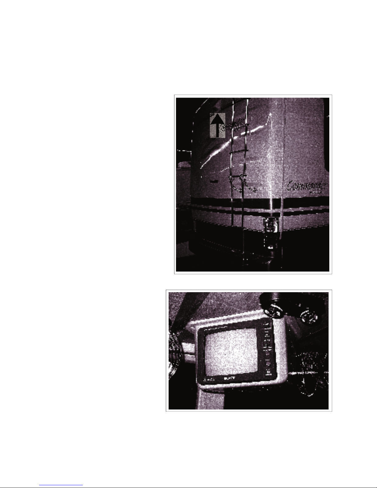
6-8
An optional rear view camera/monitor system is available to mount on the back of the unit to provide a
view of the back of the unit.
COMMANDER / EMBASSY
The camera is mounted to pick-up a
view of the area behind the unit for
2.
The monitor is mounted so it is visible
to the driver to assist in backing up or
driving.
3.
a.
In this mode, the system operates
only when the system is turned
on. It is not recommended that it
when driving as it can be very
distracting.
b.
In this mode, the system automati-
cally comes on when the trans-
assist in backing up. It goes off
when the transmission is shifted
4. Refer to the camera/monitor system
and system instructions.

7-1
The motorhome has been designed to provide the driver and passengers maximum comfort and conven-
to review the safety section at the front of this manual and the chassis manual before travelling in the
7.1 PREPARATION
7.2 BAGGAGE LOADING
or in the bottom of the baggage compart-
or weight capacity and do not exceed vehicle
7.2.1 ROOF LOADING
Your motorhome may be equipped with
an optional roof rack to accommodate light
weight articles. This weight should not
of 100 lb.. Be sure each item is secured
to the roof rack and that no item extends
When the vehicle is parked, a cargo load of
Again, the combined loaded weight of the
vehicle should not exceed the GVWR.
The motorhome is equipped with a number of
designed with 165 lb. (75 kg) capacity.
Always secure your baggage and keep the
compartment doors locked when travelling.
COMMANDER / EMBASSY

7-2
7.3 VEHICLE WEIGHT-LOADED
When loading the motorhome, make sure that the
or the Gross Vehicle Weight Rating (GVWR) and
the GCWR (Gross Combined Weight Rating) are
torhome to a weigh scale and check the front axle,
side to side to maintain maximum vehicle stability.
7.4
The front-end tire/wheel alignment was done at the
factory prior to delivery based on the vehicle being
once you have established a loading pattern ac-
cording to your needs. After an initial adjustment,
checked periodically and to check tires regularly for
abnormal wear.
7.5 MAXIMUM OCCUPANCY
The belted seating positions in your motorhome
Triple E ensures that the number of seat belts on
All occupants must be in seats equipped with lap
or shoulder harness seat belts and the seat belt
fastened before travelling. Small children should
always be placed in a certifi ed child restraint
system and secured with a seat belt.
COMMANDER / EMBASSY
IMPORTANT
It is recommended that all holding
tanks be emptied before travelling to
avoid unnecessary weight.
CAUTION
The loaded weight of the vehicle
including passengers, optional
equipment, water, fuel, luggage and
all other cargo must not exceed the
GVWR or GAWR indicated on the
Vehicle Certifi cation Label.
WARNING

7-3
7.6 SEAT BELTS
7.6.1 LAP BELTS
are equipped with seat belts.
as low on the hips as possible for maximum safety
and protection.
7.6.2 SHOULDER/LAP BELTS
The driver and co-pilot seats of your vehicle are
for maximum comfort as well as safety.
adjusted and worn correctly when the seat is in the
forward facing position. The lap part of the belt
should be worn as low as possible with the shoul-
der strap diagonally across the chest, over the
shoulder but not against the neck.
Snug and low belt position are important. In case
of collision, the force will be spread over the
strong hip area rather than the weaker abdomen
area. This could prevent serious injury.
occupied when travelling.
COMMANDER / EMBASSY
described. Serious injury may result from im-
WARNING
NOTE
If you pull the strap away from the wall too
quickly, the automatic retractor may “lock”.
To free it, relax the tension and then pull it
away from the wall slowly.
CAUTION
Make sure all passengers are instructed on the release mechanisms of the
seat belts so that they are able to get
out quickly in case of emergency.
WARNING

7-4
7.6.3 CARE AND CLEANING
webbing of your seat belt. Take care not to
2. Check belts and hardware from time to time.
3. Keep belts clean and dry. If they need clean-
These may weaken the belts.
4. If you experience a severe impact, check for
and replace any damaged parts.
7.6.4 CHILD RESTRAINTS
to provide the best in safety measures for your
child in case of an accident, we make the following
2. Make sure that the system will attach to your
vehicle conveniently and provide safety for
your child every time it is used.
3. Be sure that the restraint system is suitable
and adequate for your child's age, weight
and height. Check the label for this informa-
tion.
4. Ensure that the child restraint is installed per
the instructions provided with the restraint.
7.7 MIRRORS
Whether your vehicle is equipped with standard
or power electric mirrors, always check the adjust-
The power electric mirrors ( Commander only) may
you experience the best visibility. When you have
adjusted both mirrors for maximum visibility, place
the selector switch in the middle, neutral position
to cut off the power to the switch. This will prevent
accidental mis-adjustment of mirror settings.
The power switch adjustment is intended for fi ne
correction in mirror settings. If you are unable to
adjust your mirrors, you may need a coarse ad-
justment. This can be done by loosening the set
screws at the ball and socket of your mirror (see
tighten the screws. After this, fi ne adjustment
should be possible.
Your mirrors may also be equipped with defogging
or de-icing elements. The ON-OFF switch for the
controls.
COMMANDER / EMBASSY
Set screw location

7-5
7.8 FREE STANDING DINETTE (Optional)
Your motorhome may be equipped with a free
standing dinette. While travelling, these should
always be secured with the harness provided to
Rotate the fuel cap slowly and only far enough
for the pressure to be released i.e. until any
“hissing” sound stops. Then remove the cap.
2.
Do not overfi ll the fuel tank. Fill only until the
automatic shut-off valve cuts out. This allows
for expansion of the fuel and vapor space as
the fuel warms up in your fuel tank.
COMMANDER / EMBASSY
sparks and smoking material away from fuel or
fl ammable fumes. Extinguish all pilot lights.
fl ammable fumes. Extinguish all pilot lights.
7.9 REFUELLING
WARNING
WARNING
CAUTION
Overfi lling the fuel tank may cause
damage to the fuel evaporative
emission system.

7-6
3.
Check in the Chassis Manual for capacities.
4.
Use only gasoline with this vehicle. The
tube, to prevent the vehicle fuel tank from be-
Commander Embassy
Fuel 75 (284) 75 (284)
Capacity
Gal (litre)
Table 1 Fuel Tank Capacities
COMMANDER / EMBASSY

8-1
The Triple E Motorhome is designed with features that allow the driver/occupants to resolve emergencies
or failures when travelling. Review this section to be familiar with the recommended procedure to resolve
these conditions or situations. Review this section with all new drivers and before each trip.
LIGHTS
to the system on an automobile. Both the
front and rear turn signals fl ash in unison
when the system is turned on.
Although the control switch is normally
the chassis manual for details.
on the side of the roadway. The intermit-
tent fl ashing lights will alert other motorists
to a potential hazard and to take extra
care. The system is designed to continue
to fl ash when the switch is on even though
the ignition key is removed and you have
torque. Always use an accurate torque wrench
when mounting the wheel. Check the torque and
the torque at each oil change.
Safety Reminders:
2. Turn off the engine and set the parking brake.
3. Turn on the hazard warning fl asher.
4. Block both front and back of the tire on the op-
5. If the ground is soft, use a support board under
the jack to keep the jack from sinking.
6. Make sure to use only the jacking points de-
scribed in your chassis owner's manual.
7. Never get any part of your body under the
vehicle while jacking or while it is suspended.
When you have a fl at tire while driving, slow the
vehicle gradually and pull off to the side of the
control. Stop on a level fi rm surface and engage
alert other drivers to use extra caution when driving
to place jack under the frame. Review and follow
all safety precuations listed.
COMMANDER / EMBASSY

8-2
ately.
2. Shut engine off.
3. Check for proper coolant level in the recovery
tank. The coolant level should be between the
“full” and “add” marks on the tank.
4.
a. Check for leaks at hose connections,
throughout the cooling system. Make sure
the belts are tight and that the cooling fan
b. Add coolant to the recovery tank as soon
as possible.
c. If coolant is being lost due to leaks; if the
fan belt is broken or too loose; if the red
warning light stays on, stop the engine
5. Check the radiator face for obstructions such
as a build up of bugs. Have a professional
service shop clean your radiator if obstructed.
6. Once the temperature gauge returns to normal,
Do not tow the motorhome in an attempt to
start it. The powertrain is not designed to
transmit torque to turn the engine over for
starting.
a.
If the chassis battery does not have suf-
fi cient charge to start the engine, depress
and hold the battery boost switch to route
the coach batteries energy into the circuit
to start the engine. Release the switch
when the engine starts.
b.
Jump Starting:
Refer to Section 8.5 “Jump Starting”.
2.
Vehicle Break-Down:
When the vehicle breaks down, it should be
towed in for repair by an approved towing
service. If the vehicle breaks down on the
Call an approved towing service to come and
service what kind of vehicle it is and its weight,
will then dispatch a proper sized tow truck for
COMMANDER / EMBASSY
The drive shaft must be removed before tow-
transmission.
cause severe burns.
WARNING
WARNING

8-3
When the vehicle batteries do not have suffi cient
charge to start the engine, there are two ways to
start the unit:
Depress and hold the switch on the left side
of the dash to connect the coach batteries
starting. Release the switch when the engine
starts. This will remove the battery from the
circuit.
2.
Jump Starting:
Open the electrical utility compartment and
connect the jumper cables to the battery
The negative should be connected from the
cle providing the boost to the chassis of the
vehicle needing the boost.
COMMANDER / EMBASSY
NOTE
See section 10.3.4 for battery
maintenance information.

9-1
The motorhome is designed to be your home on
wheels while traveling in comfort. This section will
cover the items that must be done or considered in
order to obtain the maximum satisfaction from your
The motorhome can be stopped and parked
just like an automobile. However always
ance must be provided.
a.
Large mirrors are mounted on both sides
of the cab to provide rearward visibility for
the drivers. However, they do not provide
visibility directly behind or on top (clear-
ance) of the unit.
b.
An optional rear camera/monitor can be
cle (refer to Section 6.).
c.
Spotters:
The best results are obtained when an-
other person helps guide the driver in
and spotter should agree to the meaning
of hand signals before starting the backing
a position that is visible to the driver while
3. Always set the parking brake and place chocks
SYSTEM (OPTIONAL)
the motorhome must be levelled for them to func-
tion properly.
Your motorhome may be equipped with the option-
al Hydraulic Levelling System which is designed to
When using the levelling system:
a. Shift transmission to the PARK position
and set the park brake fi rmly. Turn the
b. Turn the system on by pressing the ON
COMMANDER / EMBASSY
IMPORTANT
When parking your motorhome on a uneven site, always park with the front of your
motorhome facing downhill. This allows
you to raise the front of your motorhome
in order to level it. When you place your
transmission lever in PARK, this locks
only the rear wheels. If you raise the rear
wheels with your levelling system your
vehicle could roll off the jacks or cause
undue pressure on the jacks.

9-2
c. Operate the joy stick
controls to level the
d. Check that all jacks
are down. Place
e. A yellow light indicates that the end or the
side of the motorhome is low. Move the
or end suffi ciently. In that case you may
f. Once your motorhome is level, any
jacks not extended may be lowered to
the ground to provide additional stability
against winds or movement in the mo-
torhome.
g. Press the OFF button and turn the ignition
off.
a. Remove all objects from underneath the
stands clear.
b. Move the Jack Levers to the storage/travel
c. Check all warning lights. They should all
d. Check underneath your motorhome to
h. If the system fails and the jacks do not
shooting Tips in the Operator's Manual for
the system.
operating the Levelling System.
vehicle for tire changing or service.
COMMANDER / EMBASSY
WARNING
CAUTION
Do not rely only on the warning lights
to indicate the position of the jack
levers. Make sure they are in the up
position before moving the vehicle.
For more information on your Hydraulic Levelling System, check in your
Operator's Manual. it contains more
detailed instructions, precautions and
technical information.

9-3
A motorhome may be equipped with an optional slide out room to provide more living area for the oc-
cupants. Triple E supplies a video explaining the operation of the slide out system with each slide out
9.3.1 SLIDE OUT
ROOM-POWERED
slide out room:
IMPORTANT
2.
a. If this is the fi rst time you are
operating the slide-out, take time
to view the video on Operating the
your dealer at the time of delivery.
b. Level the motorhome following
the instructions in Levelling Your
c. Make sure there is adequate
space beside your motorhome for
the slide-out room to be extended.
d. Remove the two travel locks
slide unit or above the slide-out on
all other side models.
e. Check the interior of the slide-
out to make sure there are no
obstructions on the fl oor or lean-
cabinet doors.
f. Check the exterior of the unit to
closed and any obstructions are
If the unit is not properly
levelled before extending the
room, the slide out mechanism may bind and be damaged. The levelling jacks
must be down and the lights
on the jack control panel on
in order for the slide out control to operate.
COMMANDER / EMBASSY
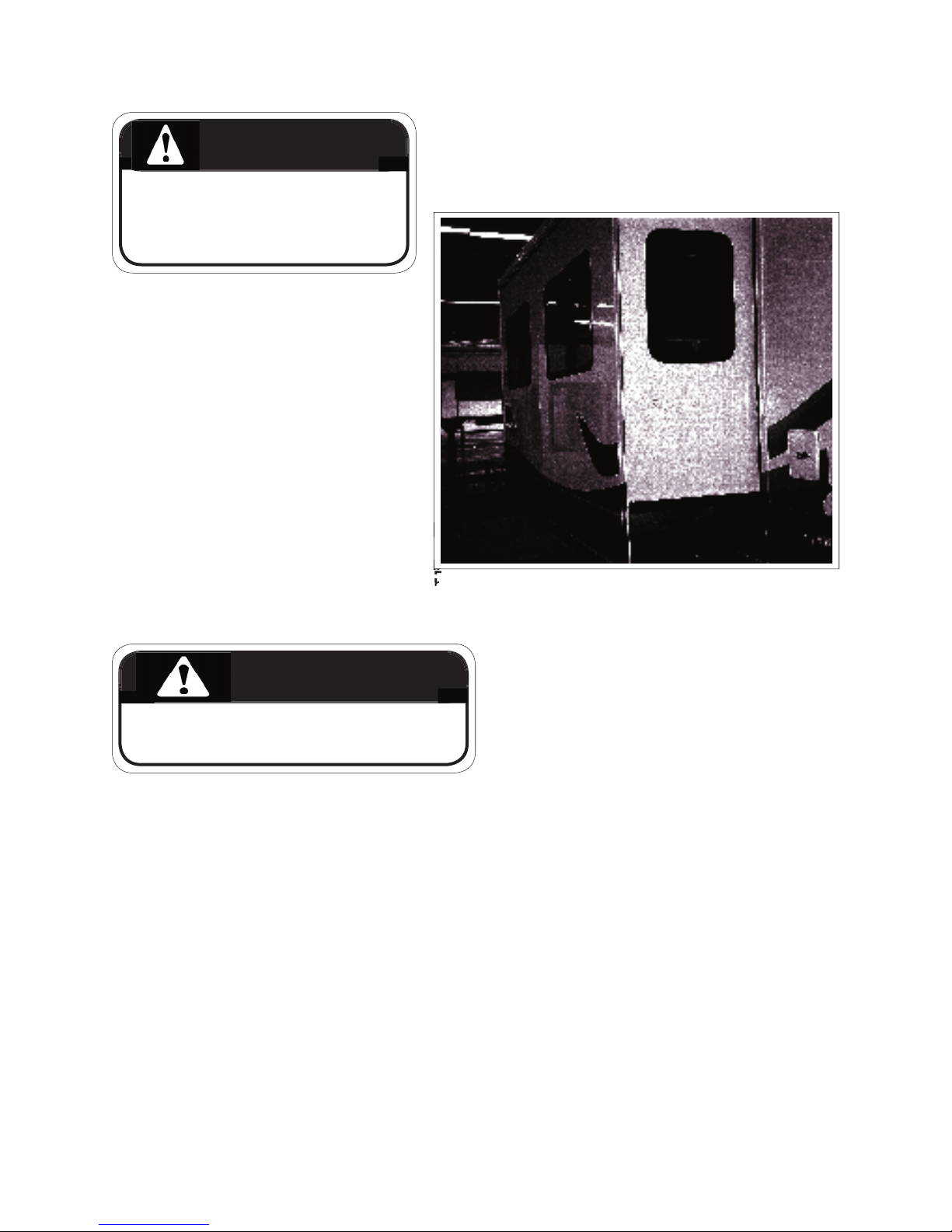
9-4
COMMANDER / EMBASSY
of the interior and exterior path of the slide-out
as you extend it, and just as important when you
fore extending the slide-out.
curely before moving the motorhome.
3.
To Extend:
On the slide out room control panel, turn
the power lock key to “on’, press and hold
the control switch located above the en-
trance door until it is fully extended. Make
sure it is fully extended so that all weather
seals will be in their proper alignment.
4.
To Retract:
Be sure that there are no obstructions inside
or outside the motorhome that would prevent
sition and turn the jack control panel on. Press
and hold the control switch on the slide out
control until the room is back in place. Install
the travel locks and prepare the rest of
the motorhome for travel. Turn key switch on
the slide out control to the "off" position and
5.
Set-Up:
Service by a professional, adjustments, regu-
seals as needed will extend the life and com-
fort of your slide-out unit.
6.
Seals:
Cracked and worn weather seals may allow
cause premature deterioration of the interior.
and have them replaced if necessary.
However, extended travel and use in severe
weather conditions may cause a more rapid
deterioration of some components, especially
weather seals. In some extreme circumstanc-
WARNING
IMPORTANT
The hydraulics that operate
the slide-out are run by a 12volt pump. When operating
the slide-out, make sure your
batteries are fully charged or
you are hooked up to 120 volt
power. You may also choose
to use the Generator (optional) on your motorhome.
WARNING
CAUTION
Never move your motorhome with the slide-out
extended. Severe damage
could result. Before moving the motorhome, the
slide-out must be securely
retracted and all travel locks

9-5
COMMANDER / EMBASSY
9.3.2 SLIDE OUT ROOM EMERGENCY OPERATION
The slide out room and optional bedroom slide
out can be manually retracted in case of sys-
tem failure. Refer to the Triple E supplied video
and the HWH or Power Gear manual for further

9-6
TROUBLESHOOTING
a. The most common cause of malfunction is
b. Run the motorhome engine while operat-
to the batteries, or
c. Connect your shoreline to an external 120-
volt power source. This will activate the
converter and charge the batteries, or
d. Reduce the electrical load to a minimum
ances.
2.
Sticking or Binding:
a. If the motorhome is not levelled and sta-
and stable. Level the motorhome prior
to extending the slide, to ensure it works
smoothly.
b. If the slide-out has been in one position
a tendancy to stick. DO NOT use petro-
cause premature seal deterioration.
Your Commander can be equipped
with an optional central vacuum system
This unit operates on the 120 volt sys-
tem requiring that you be hooked up to
shore power or run it off the generator.
sure the vacuum bag is not full. Fail-
affect the performance of the vacuum.
and instructions on the proper use and
function of this system.
al and short-term occupancy. In case of extended
occupancy there are a few things regarding humid-
the motorhome can accumulate and may damage
the motorhome. Moisture condensing on the win-
dows is a sure sign that the humidity inside your
your motorhome we suggest the following:
windows and vents. This will allow fresh air to
fl ow through and reduce the moisture content.
2. Reduce moisture released inside the mo-
torhome. Run the bathroom fan when using
the bathroom and turn on the range hood fan
while cooking. This will remove unnecessary
to dry will also add to humidity levels within the
COMMANDER / EMBASSY

Your Commander / Embassy is equipped with
two electrical systems operating on separate volt-
ages - a 12 Volt DC System and a 120 Volt AC
The 12 Volt DC System draws its power either
from the engine's charging system while driving
or from the coach batteries when parked. An
vent the engine batteries from being drawn down
when parked and the coach systems are in use.
The 120 Volt AC System operates either from the
optional 120 Volt generator installed in your mo-
torhome or from the outside shoreline connection.
All 12 volt systems operate through a single pow-
When connected to an outside electrical util-
or when running your 120 volt generator, the
converter supplies 12V power and also charges
coach batteries. All equipment that normally is
optional 120 volt generator. These include:
2. Refrigerator (when set to 120 volt)
3. Microwave Oven
4. Ice Maker
5. Central Vacuum
6. All 120 Volt Electrical Outlets
7. Coffee Maker
8. Energy Management System
COMMANDER / EMBASSY
(SHORELINE)
campground as to proper polarity and grounding.
component failure, injury or death.
component failure, injury or death.
To connect your motorhome to an external power
source, pull the cord through the cord hatch and
some slack is present in the cable.
The external utility power cord (also called the
“shoreline”) is stored in the compartment on the left
WARNING

COMMANDER / EMBASSY
This panel contains the fuses for the 12 volt sys-
tem, circuit breakers for the 120 volt system. 120V
The breaker panel protects all 110-volt equip-
overload, from a short in the wiring or a short
of electricity in the system and prevents dam-
age or fi re.
OFF and then ON. If a breaker “trips” again,
this could mean that there is a short in the
wiring or in the equipment and both should be
checked and serviced by a qualifi ed techni-
cian.
There is a singular panel switch of either 30
or 50 amps which protects the entire electri-
cal system. Become familiar with the loca-
tions of the main 110v breaker and check it
fi rst if electrical problems should be experi-
ELECTRICAL PANEL SHOWN

COMMANDER / EMBASSY
INTERRUPTER (GFCI)
Various outlets in the motorhome, particularly
those near sinks and water supplies, are con-
and press the reset button on the outlet.
will fi nd a GFCI outlet in the bathroom and outside
The GFCI will not eliminate completely all electric
shock. Small children or persons with a heart
condition should be extra cautious and could still
the bathroom will trip when a fault occurs at an ex-
terior plug. Both plugs are GFCI protected through
the bathroom circuit. If the exterior plug does not
work, check the bathroom GFCI receptacle.
WARNING

when handling the generator and its components.
standing on wet ground or in water.
Any repair of the generator should be done by
authorized service centers only. Never attempt to
off.
engine is running.
2.
Asphyxiation:
All internal combustion engines produce carbon
gas is poisonous, colorless, odorless, tasteless
and lighter than air. These gases can readily be
drawn into your motorhome. Take the following
a. Do not run the generator and a ventila-
tor fan at the same time. This could draw
b. Do not open windows or ventilators on the
side where exhaust pipes are located.
COMMANDER / EMBASSY
c. Park so that winds will carry gases away
from the vehicle. Be aware of potential
d. Do not operate the generator if there is
any obstruction such as vegetation, snow,
fumes under or into the motorhome.
WARNING
WARNING
WARNING
IMPORTANT
Check the oil level regularly during
frequent use of the generator. Refer
to the Manufacturer's Manual for
specifi c information.

The generator switches are located:
a. On the dash board, within easy reach
from the driver's seat.
b. Above the main entrance door, part of
the main control panel.
COMMANDER / EMBASSY
The generator starter does not draw current
from the engine batteries so the ignition does
Starting:
a. See Generator Manufacturer's Manual
for specifi c instructions.
b. For Embassy, plug in the power cord
7) On the Commander, the switch is
done by an automatic power transfer
switch. (See Section 10.2.3)
c. Disconnect all electrical loads. (Turn
off all lights, appliances, equipment,
d. Press generator start button, hold until
e. Wait for engine to run smoothly before
turning on lights and appliances.
f. Be familiar with the output capacity
and capability of your generator.
f. Be careful not to overload the genera-
tor. See your manual for information.
3.
Stopping:
a. Turn off lights and all appliances before
shutting off engine. Let the engine run
at no-load for a few minutes to allow the
b. Press the OFF switch and hold until engine
comes to a complete stop.
CAUTION
Overloading the generator for
long periods of time can cause
high temperatures that could
result in damage to the generator windings. Keep electrical
loads within the wattage ratings
specifi ed in your manual.

(COMMANDER ONLY)
This Commander model is equipped with an
automatic power transfer switch that transfers the
tor power source. It automatically transfers all the
shoreline must be unplugged to utilize power from
the generator.
When the generator is started, the transfer unit by-
allow for easy starting. Then when the generator is
When the shoreline is plugged in to an outside
switches away from the generator to the shoreline.
shoreline.
than the engine pickup tube, to prevent the vehicle
from being without fuel while on site.
COMMANDER / EMBASSY
sparks and smoking material away from fuel or
fl ammable fumes.
WARNING

The DC voltage system in your motorhome consists of two separate and yet connected battery systems:
2. The auxiliary or motorhome batteries (or coach
(CHASSIS)
These are used to operate the starter, the automo-
tive accessories and all the controls found on the
fans, the exterior lights, the horn, speed control,
windshield wipers, etc..
cables be disconnected when storing the unit for
an extended period of time.
(COACH)
These supply power to all the 12-volt lights and
fan, interior lights, holding tank and water level
teries are dead. Refer to “Auxiliary Start Switch” in
this case.
These batteries are “deep cycle” RV batteries
designed to provide power over a long period of
time and to stand up under the frequent drain and
The motorhome has an easy access electric coach
the store position, all 12-volt coach accessories,
the Embassy a manual switch is located under the
COMMANDER / EMBASSY
(COMMANDER ONLY)
IMPORTANT
Removing battery cables from the
automotive (chassis) battery can clear
the engine/transmission logic modules.
These modules will recalibrate themselves once the vehicle is reconnected
to the 12 volt system and the engine is
started.

All 12-volt circuits are protected by either a circuit
same amperage. The label on the panel identifi es
The fuse panel is located next to the circuit-break-
Automotive batteries are reservoirs of 12-volt
from the battery it has to be replaced in order for
the battery to continue functioning. This energy is
Two conditions can destroy the function of a
when a battery is stored in a discharged state.
This situation requires replacement of the bat-
tery. The second is freezing. A battery must
2.
a. Disconnect the battery cables during long
b. Hook up a battery charger at least once a
3.
If you do not intend to use your motorhome for
a longer period of time it might be a good idea
to remove the batteries from the motorhome
and store them in a cool dry location on a
wood or rubber pad. The batteries shoud be
charged once a month in order to prolong their
eyes, fabrics, or painted surfaces. The elec-
trolyte is a sulphuric acid solution which could
cause serious personal injury or property dam-
age. Wear eye protection when working with
4. Additional maintenance suggestions:
a. Check the external condition of the battery
case.
b. Make sure batteries are always securely
fastened down.
c. Make sure battery clamps are tight and
free of corrosion.
COMMANDER / EMBASSY
WARNING

d. Keep the battery and terminals clean.
Accumulations of acid fi lm and dirt may
e. To clean the battery, wash it with a di-
clean water. Foaming around terminals or
on top of the battery is normal acid neu-
tralization.
f. Dry the cables and terminals before rein-
stalling them, and don't use grease on the
ter you have cleaned and reinstalled them.
g. Whenever batteries are removed and
tive cables are attached to the correct
terminals. (Positive to positive and nega-
tive to negative). The same is true when
you use a “fast charger”, disconnect the
cables from your battery.
attempt
to recharge a frozen battery.
h. If you do not have maintenance-free bat-
teries, check the battery fl uid level and fi ll
with distilled water if necessary.
overfi ll.
i. Have the specifi c gravity of the battery
fl uid checked when you have your vehicle
serviced.
contacts the battery terminals or metal connected
to them, a short circuit could occur which could
cause personal injury or fi re.
COMMANDER / EMBASSY
WARNING
NOTE
Make sure you don't allow
any baking soda solution
to get into the battery. This
can neutralize the battery
acid.

On your control panel you will fi nd a gauge
which tells you the level of charge in your
coach or auxiliary batteries.
CONNECTOR
Your motorhome is ready for trailer or car
towing. It has a wiring connector plug at the
terminals in the plug. These are standard for
all 7-pin trailer plugs.
can be installed by your dealer.
COMMANDER / EMBASSY

COMMANDER / EMBASSY

COMMANDER / EMBASSY

Access
COMMANDER / EMBASSY

COMMANDER / EMBASSY
THIS PAGE LEFT INTENTIONALLY BLANK

compressed into liquid form for easy transporta-
tion and storage. It is the energy source for your
The LP gas system is designed and built to ad-
these include: tank overfl ow valves, LP gas detec-
tor, and carbon monoxide (CO) detectors. As well,
Observe the following precautions for the safe use
of LP gas.
you suspect a leak, turn off the LP gas supply
2. Do not tamper with any part of the LP gas
system, piping or regulator. Service and main-
tenance should be performed only be qualifi ed
3.
4. Check the entire system for leaks every time
the tanks are fi lled. Take time regularly to
5. Turn off the LP gas supply valve when not us-
6. The tank supply valve is designed to be
tightened by hand only. If the valve requires a
wrench for tightening it is defective and should
7. Tanks should never be fi lled above the 80 %
8. Make sure all appliance vents are open and
free of obstruction when using the LP gas sys-
tem.
tional vehicle industry standards require that all
times in case of emergency.
jects be careful not to damage any gas lines or
There are two types of LP (Liquefi ed Petroleum)
simply LP.
fall below -40 degrees C (-40 degrees F). At tem-
COMMANDER / EMBASSY
CAUTION
These instructions are provided as a
general guideline only and may not be
complete. To ensure proper service and
safety, always take your motorhome to an
authorized Triple E service center.

at temperatures below 32 degrees F or 0 degrees
temperature and will continue to convert from a liq-
their area. If you travel from a warmer part of the
country to a colder area you may want to check to
The storage tank for the LP gas is mounted
the vehicle frame. It is accessible only
from outside the vehicle. The tank valve is
to the regulator. Before opening the supply
valve, make sure all controls for the various
appliances are in the OFF or PILOT OFF
accumulating in the motorhome.
The tank size is the approximate usable volume
which is about 80% of the total tank volume.
Commander Embassy
Tank Size 25.3 (95.8) 25.3 (95.8)
Gal (l)
COMMANDER / EMBASSY
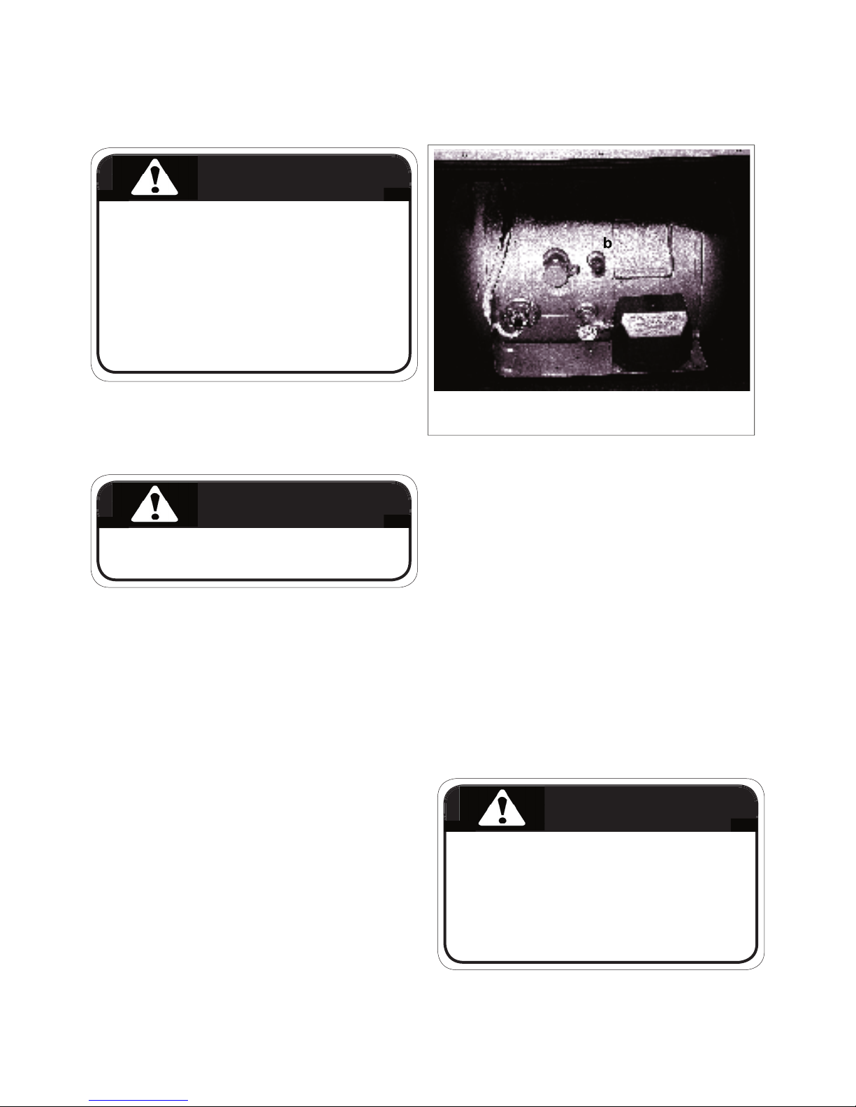
a. Fill b. Overfl ow c. Outage d. Vapor
attendant.
sparks and smoking material away from fuel or
fl ammable fumes.
2. Make sure your vehicle is level when fi lling the tank.
3. Make sure all pilot lights are OFF before refuelling any
of the gas tanks on your motorhome.
4. Do not smoke or have any open fl ame in the area
where refuelling is taking place.
5. When testing for leaks in the LP system use a soap
and water solution. Never use an open fl ame to test
for leaks.
6. Never fi ll the LP tank when either the engine or the
generator is running.
7. Keep all protective covers and caps in place.
7. Keep all protective covers and caps in place.
during travel. Always refi ll empty LP gas container
as soon as possible.
when liquid appears at the overfl ow valve, this indi-
cates that the tank is full (often called a 10% valve)
which contacts the liquid level at 80% of container
capacity allowing 20% for expansion.
valve and bleed gas in well-ventilated area until
white liquid stops. Overfi lling may cause damage
to regulator and cause malfunction of LP gas appli-
ances.
The tank is permanently mounted to the mo-
torhome frame. Therefore the vehicle must be
taken to a fuelling station to be fi lled.
try. Check with the Yellow pages in your telephone
or ”Propane”.
overfl ow valve when refuelling. Space must be
tainers in your motorhome. Gases may inadvert-
ently be discharged into the room which could
COMMANDER / EMBASSY
WARNING
a
c
d
WARNING
IMPORTANT
The LP tank has an automatic 80%
stop-fi ll device to prevent over fi lling
of the tank.
WARNING

After tank has been fi lled:
odically to be sure they are tight. When testing
for leaks, use soapy water (never a match).
2. If gasoline or LP gas fumes are noticed at any
time, the cause should be determined and cor-
winter operation to prevent freeze-up.
3. Before opening the control valve at the LP gas
container, check that controls for all gas appli-
ances are in the off position. If this is not done,
creating a fi re or explosion hazard.
4. LP gas is also potentially lethal if inhaled.
dealers to prevent this from happening). To help
avoid this situation, keep the control valve closed
when not in use even when the tank is empty. This
you may ask your LP gas dealer to inject a small
amount of dry methyl alcohol into the tank to ab-
sorb the moisture.
at warmer temperatures. Under cold conditions
this process slows down dramatically. When
furnace, for example, the fuel may not vaporize
a high level. In this case you may have to reduce
the consumption of fuel by lowering the tempera-
ture setting on the furnace, reduce the consump-
tion of hot water, turn up the temperature setting
on your refrigerator or switch from LP to electric
where possible.
The regulator is preset. Do not attempt to adjust it.
This should only be done by an authorized service
outlet. The regulator should not be exposed to the
fi lled, or there may be impurities in the propane.
to malfunction.
you may have air trapped in the tank. The air will
air by the LP gas dealer. During the tanks fi rst fi ll,
on certain roads or through tunnels. Check state
or provincial regulations to make sure your trip will
The LP tank regulator has a plastic cover
to protect it from the weather. This should
The pressure regulator has a vent hole on the
and not obstructed in any way.
there is a small amount of moisture in the fuel
COMMANDER / EMBASSY
out regulator.
out regulator.
WARNING

tor alarm sounds, follow the instructions carefully.
2. Do not touch electrical switches.
3. Shut off the LP tank valve.
4. Open doors, windows and roof vents.
5. Leave the area until the odour is gone.
6. Have the system checked for leaks and make the necessary
corrections and repairs.
COMMANDER / EMBASSY
A standard LP gas detector has been installed in
your unit.
This warning label has been located in the cook-
supply of fresh air for combustion. Unlike homes,
the amount of oxygen supply is limited due to the
size of the recreational vehicle, and proper ventila-
tion when using the cooking appliance(s) will avoid
dangers of asphyxiation. It is especially important
that cooking appliances not be used for comfort
when the appliance is used for long periods of
fort heating. Cooking appliances need fresh air
for safety operation. Before operation:
2. Open window.
2. Open window.
LOCATED ON INTERIOR LOWER
WALL)
WARNING
WARNING
NOTE
Your unit is not equipped with an
automatic propane shut-off valve.
WARNING

Your motorhome is designed with a fresh water,
together.
There are two sources for fresh
water in your motorhome:
your motorhome.
2. By connecting to “city water”
sink, shower, bathroom, toilet
and the water heater.
The water system built into your
similar to the system used in
your home. A 12-volt self-prim-
water from the fresh water stor-
age tank to all cold faucets and
the water heater. An automatic
water pump maintains a positive
The utility compartment located on the drivers side
of the vehicle contains, the water pump, the pota-
drain.
COMMANDER / EMBASSY
The water system of the vehicle is contained in
the utility module on the road side of the coach.
The water pump and fi lter are located in the utility
the rear bed or under the fl oor depending on the
The utility compartment located on the drivers
side of the vehicle contains, the water pump, the

The water tank is not a pressure
vessel. The fi lling procedure is
done via a water pressure sys-
tem and cannot be done without
available water under pressure.
drain located underneath the tank
area is open, free and clear of
any obstruction before attempting
to fi ll the tank. A blocked vent
during fi lling could cause serious
damage to the tank and even the
The water pump is designed to supply water from
the fresh water tank to the various areas of your
the pump comes on automatically and pressurizes
the various water lines.
The water pump has an inlet screen type fi lter
teriorates, clear out this screen. (See pump owners
COMMANDER / EMBASSY
4. Turn on water supply.
5. Check the Monitor System inside the mo-
torhome for levels as the tank is fi lling. When
the tank is close to full, check for overfl ow at
the overfl ow drain. Turn the supply off as soon
as water fl ows from the drain.
6. Turn the systems valve back to normal, after
7. Turn pump switch back to on and the system is
When fi lling fresh water tank:
city water inlet connection.
2. Set the water pump switch
for the motorhome system to
the off position.
3. Turn systems valve to “Tank
shown, Embassy fi ll inlet located on sidewall of unit)
Valve
IMPORTANT
Never allow a full fl ow at the over-
IMPORTANT
If you are starting from a dry system
or if some faucets have been open
during the tank fi lling procedure, you
may want to slowly open all faucets
one at a time to allow any trapped air
to escape from the system.

The master switch for the water pump
the on position, the pump will automati-
cally activate when any faucet, shower
or toilet is being used. On the Com-
the galley, in the bathroom and at the
the pump on or off. This makes it more
convenient to use the system without
time.
torhome for any period of time or while
driving. A slow leak in a faucet or con-
and the battery.
COMMANDER / EMBASSY

water fi lter. This fi lter is located on the
water pump.
clean or replace it at least annually to
assure a clean supply of water.
COMMANDER / EMBASSY
WATER PUMP INITIAL START-UP
the water heater valve.
2. Turn water pump switch off.
3. Fill water tank.
4. Open faucets, both hot and cold.
5. Turn pump switch on.
6. Close each faucet (cold and hot) as soon as
water fl ows steadily.
7. Check to see that pump stops after all faucets
are closed.
8. Pump is now ready for automatic operation. It
will start whenever a faucet is opened.
The water system compart-
access to the compartment
for the water line. Route the
close the compartment door
when at a campsite.
Water Filter
Access Hole
 Loading...