

TRIPATH TECHNOLOGY TA2022 Datasheet
TECHNICAL INFORMATION
Stereo 90W (4
Digital Power Processing
ADVANCED INFORMATION - December 2000
ΩΩΩΩ
) Class-T Digital Audio Amplifier using
TM
Technology TA2022
General Description
The TA2022 is an 90W continuous average, per channel, Class-T Digital Audio Power
Amplifier IC using Tripath’s proprietary Digital Power Processing
amplifiers offer both the audio fidelity of Class-AB and the power efficiency of Class-D
amplifiers.
Applications
!"DVD Players
!"Mini/Micro Component Systems
!"Home Theater
!"Powered Speakers
Benefits
!"Fully integrated solution with internal
FETs
!"Dramatically improves efficiency versus
Class-AB
!"Signal fidelity equal to high quality linear
amplifiers
!"High dynamic range compatible with
digital media such as CD, DVD, and
internet audio
Features
!"Class-T architecture
!"High Power
!"100W @ 4Ω, 1.0% THD+N
!"90W @ 4Ω, 0.1% THD+N
!"60W @ 8Ω, 0.1% THD+N
!"“Audiophile” Quality Sound
!"0.015% THD+N @ 70W 4Ω
!"0.015% THD+N @ 45W 8Ω
!"0.10% IHF-IM @ 25W 4Ω
!"High Efficiency
!"92% @ 88W 8Ω
!"87% @ 125W 4Ω
!"Dynamic Range = 102 dB
!"Mute Input
!"Over-current protection
!"Over and under-voltage protection
!"Single ended outputs
!"Outputs can be operated in bridged mode
!"32-pin SSIP package
TM
technology. Class-T
1 of 29 TA2022, Rev. 0.90, 12.00

TECHNICAL INFORMATION
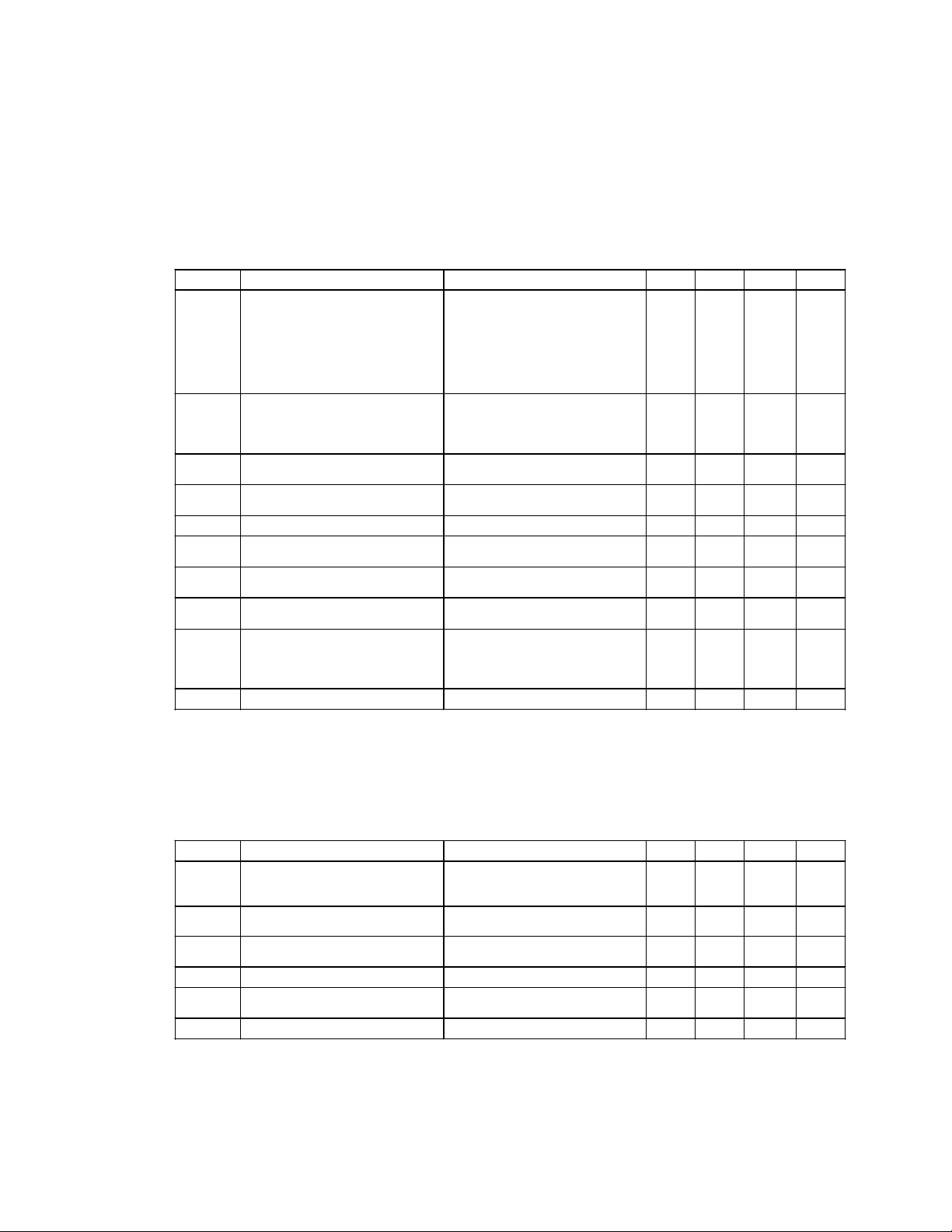
Absolute Maximum Ratings
SYMBOL PARAMETER Value UNITS
VPP, VNN Supply Voltage (VPP1, VPP2, VNN1, VNN2) +/-40 V
V5 Positive 5V Bias Supply
VN10 Voltage for low-side FET drive VNN + 13 V
T
STORE
T
A
T
J
ESDHB ESD Susceptibility – Human Body Model (Note 3)
ESDMM ESD Susceptibility – Machine Model (Note 4)
Voltage at Input Pins (pins 18, 19, 23, 24, 26, 28, 29, 30, 31, 32)
Storage Temperature Range
Operating Free-air Temperature Range (Note 2)
Junction Temperature
All pins (except pin 27)
Pin 27
All pins
Note 1: Absolute Maximum Ratings indicate limits beyond which damage to the device may occur.
See the table below for Operating Conditions.
Note 2: This is a target specification. Characterization is still needed to validate this temperature range.
Note 3: Human body model, 100pF discharged through a 1.5KΩ resistor.
Note 4: Machine model, 220pF – 240pF discharged through all pins.
Operating Conditions
SYMBOL PARAMETER MIN. TYP. MAX. UNITS
VPP, VNN Supply Voltage (VPP1, VPP2, VNN1, VNN2) +/-12 +/-31 +/-36 V
V5
VN10
Positive 5V Bias Supply 4.5 5 5.5 V
Voltage for low side FET drive (Volts above VNN) 9 11 12 V
Note 5: Recommended Operating Conditions indicate conditions for which the device is functional.
See Electrical Characteristics for guaranteed specific performance limits.
Thermal Characteristics
SYMBOL PARAMETER Value UNITS
θ
JC
θ
JA
Junction-to-case Thermal Resistance
Junction-to-ambient Thermal Resistance (still air)
(Note 5)
(Note 1)
-55
-40
6
to 150°
°
to 85°
°
150
°
4000
1500
200
-0.3V to (V5 +0.3V)
V
V
C
C
C
V
V
V
1.0
20
°
°
C/W
C/W
2 of 27 TA2022, Rev. 0.90, 12.00

TECHNICAL INFORMATION
Electrical Characteristics
(Notes 6, 7)
TA = 25 °C. See Application/Test Circuit on page 7. Unless otherwise noted, the supply voltage is
VPP=|VNN|=31V.
SYMBOL PARAMETER CONDITIONS MIN. TYP. MAX. UNITS
I
q
I
MUTE
VIH High-level input voltage (MUTE) 3.5 V
VIL Low-level input voltage (MUTE) 1.0 V
VOH High-level output voltage (HMUTE) I
VOL Low-level output voltage (HMUTE) I
V
OFFSET
IOC Over Current Sense Threshold TBD TBD TBD A
I
VPPSENSE
V
VPPSENSE
I
VNNSENSE
V
VNNSENSE
Quiescent Current
(No load, Mute = 0V)
Mute Supply Current
(No load, Mute = 5V)
Output Offset Voltage No Load, MUTE = Logic low
VPPSENSE Threshold Currents Over-voltage turn on (muted)
Threshold Voltages with
R
VPPSENSE
(Note 11)
VNNSENSE Threshold Currents Over-voltage turn on (muted)
Threshold Voltages with
R
VNNSENSE
(Note 11)
= 249KΩ
= 249KΩ
VPP = +31V
VNN = -31V (Note 8)
V5 = 5V (Note 9)
VN10 = 11V (Note 10)
VPP = +31V
VNN = -31V (Note 8)
V5 = 5V (Note 9)
= 3mA 3.5 V
OH
= 3mA 1.0 V
OL
0.1% R
Over-voltage turn off (mute off)
Under-voltage turn off (mute off)
Under-voltage turn on (muted)
Over-voltage turn on (muted)
Over-voltage turn off (mute off)
Under-voltage turn off (mute off)
Under-voltage turn on (muted)
Over-voltage turn off (mute off)
Under-voltage turn off (mute off)
Under-voltage turn on (muted)
Over-voltage turn on (muted)
Over-voltage turn off (mute off)
Under-voltage turn off (mute off)
Under-voltage turn on (muted)
FBA
, R
FBB
, R
resistors
FBC
20
55
45
65
0.5
2
20
-750 750 mV
62
65
162
154
79
72
42.8
40.9
22.2
20.4
174
169
86
77
-42.1
-40.8
-20.2
-17.9
138
36.5
17.8
152
-36.2
-14.8
60
80
25
178
87
47.3
24.4
191
95
-46.8
-22.6
mA
mA
mA
mA
mA
mA
mA
A
µ
A
µ
A
µ
A
µ
V
V
V
V
A
µ
A
µ
A
µ
A
µ
V
V
V
V
TA2022, Rev. 0.90, 12.00 3 of 27
TECHNICAL INFORMATION
Performance Characteristics – Single Ended
(Notes 6, 7)
TA = 25 °C. Unless otherwise noted, the supply voltage is VPP=|VNN|=31V, the input frequency is
1kHz and the measurement bandwidth is 20kHz. See Application/Test Circuit on page 7.
SYMBOL PARAMETER CONDITIONS MIN. TYP. MAX. UNITS
P
OUT
THD + N Total Harmonic Distortion Plus
IHF-IM IHF Intermodulation Distortion
SNR Signal-to-Noise Ratio A-Weighted
CS Channel Separation
AV Amplifier Gain
A
VERROR
η
I
SLOAD
e
NOUT
Output Power
(Continuous Average/Channel)
(Note 12)
Noise
Channel to Channel Gain Error
Power Efficiency
Source Current
Output Noise Voltage A-W eighted, input AC grounded 150
VPP = |VNN| = +/-31V, R
THD+N = 0.1%
THD+N = 1.0%
THD+N = 10%
VPP = |VNN| = +/-35V, R
THD+N = 0.1%
THD+N = 10%
= 70W/Channel, RL = 4Ω
P
OUT
VPP = |VNN| = +/-31V
= 45W/Channel, RL = 8Ω
P
OUT
VPP = |VNN| = +/-35V
19kHz, 20kHz, 1:1 (IHF), R
= 25W/Channel
P
OUT
0dB = 90W/Channel, R
0dB = 25W, R
P
OUT
See Application / Test Circuit
P
OUT
See Application / Test Circuit
P
OUT
P
OUT
P
OUT
VPP = +31V
VNN = -31V
V5 = 5V
= 4Ω,
L
= 10W/Channel, RL = 4Ω,
= 10W/Channel, RL = 4Ω
= 88W/Channel, RL = 8
= 125W/Channel, RL = 4Ω
= 125W/Channel, RL = 4
L
L
= 4Ω
L
Performance Characteristics – Bridged Tied Load
TA = 25 °C. Unless otherwise noted, the supply voltage is VPP=|VNN|=30V, the input frequency is
1kHz and the measurement bandwidth is 20kHz.
SYMBOL PARAMETER CONDITIONS MIN. TYP. MAX. UNITS
P
OUT
THD + N Total Harmonic Distortion Plus
IHF-IM IHF Intermodulation Distortion
η
SNR Signal-to-Noise Ratio
e
NOUT
Output Power
(Continuous Average)
(Note 12)
Noise
Power Efficiency
Output Noise Voltage A-W eighted, input AC grounded 220
VPP = |VNN| = +/-30V, R
THD+N = 0.1%
THD+N = 10%
= 100W, RL = 8Ω
P
OUT
19kHz, 20kHz, 1:1 (IHF), R
= 25W
P
OUT
= 225W, RL = 8Ω
P
OUT
A-Weighted, R
0dB = 150W
L
= 8
Ω
L
= 4Ω
= 8Ω
= 4Ω
L
Ω
Ω
(Notes 6, 7)
= 8Ω
= 8Ω
L
80
90
100
125
0.015
0.1 %
102 dB
83 dB
18.1 V/V
0.5 dB
92
60
88
0.015
87
4.59
4.61
45
%
0.05 %
0.10 %
87 %
104 dB
150
235
W
W
W
W
%
%
%
A
A
mA
V
µ
W
W
V
µ
4 of 27 TA2022, Rev. 0.90, 12.00

TECHNICAL INFORMATION
Note 6: Minimum and maximum limits are guaranteed but may not be 100% tested.
Note 7: For operation in ambient temperatures greater than 25°C, the device must be derated based on the
maximum junction temperature and the thermal resistance determined by the mounting technique.
Note 8: This specification includes the current draw from the internal buck regulator.
Note 9: This specification includes the current draw from both the TA2022 and the external feedback biasing.
Note 10: This is the current draw of the VN10 pin if an external “floating” 11V supply is used instead of the
internal buck regulator. If an external floating supply is used, the idle current draw of the VNN supply
will be approximately 20mA.
Note 11: These supply voltages are calculated using the IVPPSENSE AND IVNNSENSE values shown in the
Electrical Characteristics table. The typical voltage values shown are calculated using a
RVPPSENSE and RVNNSENSE value of 249kohm without any tolerance variation. The minimum
and maximum voltage limits shown include either a +1% or –1% (+1% for Over-voltage turn on and
Under-voltage turn off, -1% for Over-voltage turn off and Under-voltage turn on) variation of
RVPPSENSE or RVNNSENSE off the nominal 249kohm value. These voltage specifications are
examples to show both typical and worst case voltage ranges for a given RVPPSENSE and
RVNNSENSE resistor value of 249kohm. Please refer to the Application Information section for a
more detailed description of how to calculate the over and under voltage trip voltages for a given
resistor value.
Note 12: The supply voltage limitation for 4 ohm single ended (+/-31V), or 8 ohm bridged (+/-30V), is based on
the current limit protection circuitry. The current limit circuitry may be activated during large output
excursions if the recommended supply voltage ranges are exceeded. This will result in the amplifier
being muted.
TA2022, Rev. 0.90, 12.00 5 of 27
TECHNICAL INFORMATION
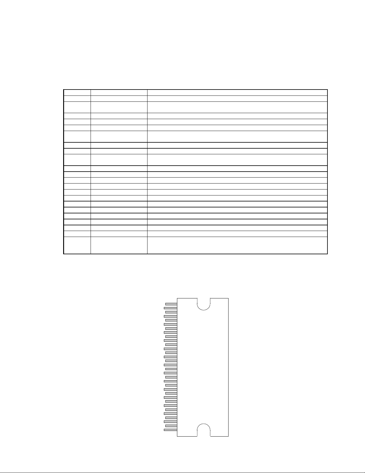
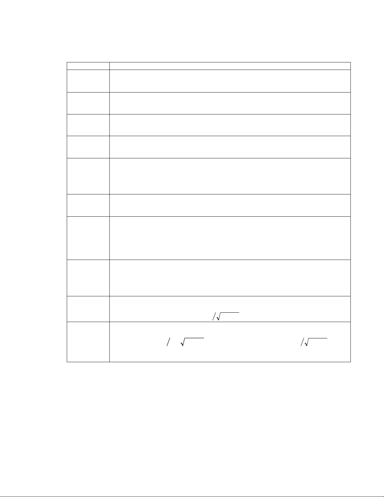
Pin Description
Pin
Function
1, 13 VBOOT2, VBOOT1 Bootstrap voltages for gate drive of high side MOSFET’s
2 VN10 “Floating” supply input. Normally connected to the output of onboard VN10 buck
3 VN10GND Power ground for onboard VN10 generator. Electrically tied to the TA2022 case.
4, 12 VPP2, VPP1 Positive power supply input pins.
5 VN10SW Switching output voltage for onboard VN10 generator (buck converter).
6 NC Not connected internally. May be connected to pin 7 without any loss of
7,10 OUT2, OUT1 Power amplifier outputs.
8, 9 VNN2, VNN1 Negative power supply inputs.
11 NC Not connected internally. May be connected to pin 10 without any loss of
14 VN10FDBK Feedback for onboard VN10 generator (nominally 11V above VNN)
15, 20 AGND Analog Ground.
16, 21 V5 5V power supply input.
17 REF Used to set internal bias. Typically 1.1V
18 VNNSENSE Negative supply voltage sense input.
19 VPPSENSE Positive supply voltage sense input.
22, 25 OAOUT1, OAOUT2 Outputs of Input Stage op amps.
23, 26 INV1, INV2 Inverting inputs of Input Stage op amps.
24 MUTE Logic input. A logic high puts the amplifier in mute mode. Ground if not used.
27 BIASCAP Bandgap reference times two (typically 2.5VDC).
28, 29 FBKGND2, FBKOUT2 Output voltage differential feedback for channel 2.
30,31 FBKGND1, FBKOUT1 Output voltage differential feedback for channel 1.
32 HMUTE Logic Output. A logic high indicates both amplifiers are muted, due to the mute
Description
converter. This voltage must be stable and referenced to VNN.
functionality or performance.
functionality or performance.
pin state, or a “fault” such as an overcurrent, undervoltage, or overvoltage
condition.
32-pin SSIP Package
(Front View)
VBOOT2
VN10
VN10GND
VPP2
VN10SW
OUT2
VNN2
VNN1
OUT1
VPP1
VBOOT1
VN10FDBK
AGND
REF
VNNSENSE
VPPSENSE
AGND
OAOUT1
INV1
MUTE
OAOUT2
INV2
BIASCAP
FBKGND2
FBKOUT2
FBKGND1
FBKOUT1
HMUTE
NC
NC
V5
V5
1
2
3
4
5
6
7
8
9
10
11
12
13
14
15
16
17
18
19
20
21
22
23
24
25
26
27
28
29
30
31
32
6 of 27 TA2022, Rev. 0.90, 12.00
TECHNICAL INFORMATION
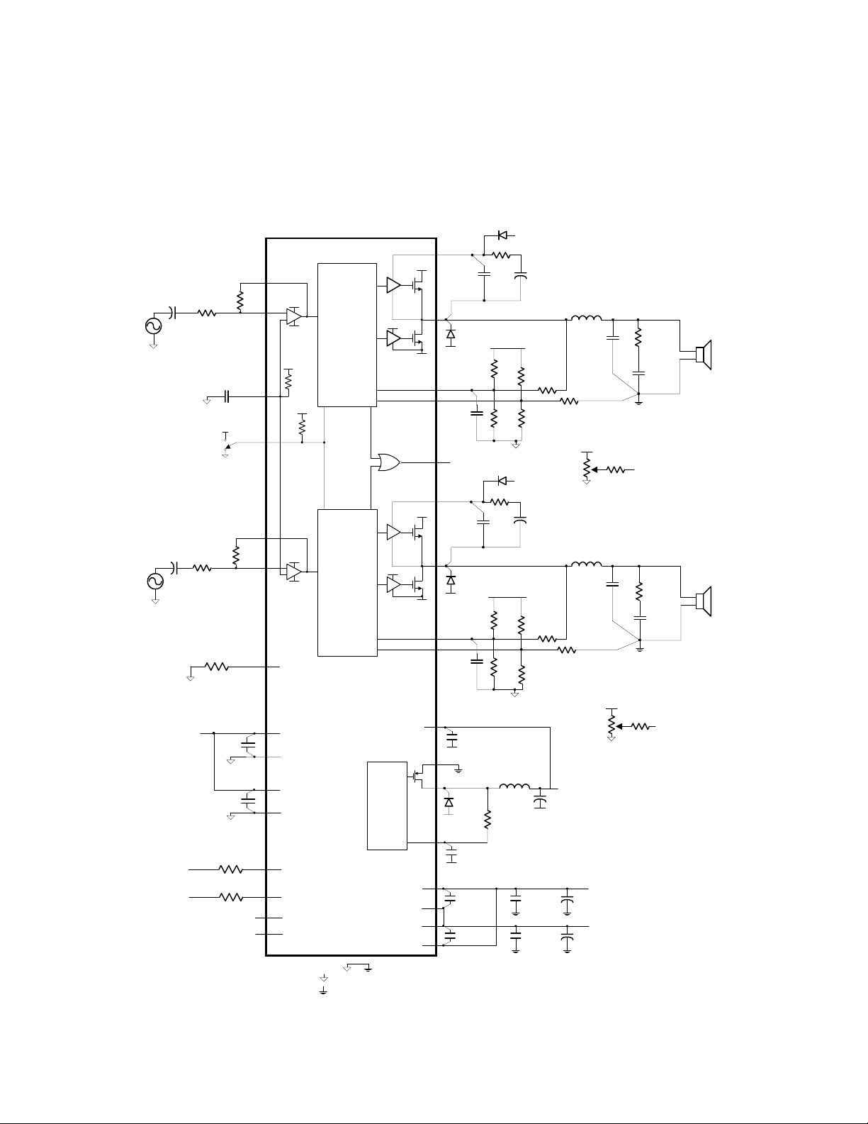
Application / Test Diagram
D
11DQ09
OUT1
D
O
MUR120
C
FB
390pF
AGND (Pin 20)
11DQ09
OUT2
D
O
MUR120
C
FB
560pF
AGND (Pin 20)
C
SW
0.1uF,35V
D
SW
11DQ09
C
SWFB
0.1uF,50V
C
HBR
0.1uF,100V
C
HBR
0.1uF,100V
B
RB 250
C
B
0.1uF
V5 (Pin 21)
R
FBA
1K
R
FBB
1.1K
D
B
RB 250
C
B
0.1uF
V5 (Pin 21)
R
FBA
1K
R
FBB
1.1K
100uH, 1A
R
SWFB
1K
Ω
Ω
Ω
L
VN10
+
Ω
VN10
Ω
+
C
Ω
SW
Ω
C
BAUX
47uF
R
FBA
1K
Ω
R
9.1K
R
FBB
1.1K
Ω
BAUX
47uF
R
FBA
1K
Ω
R
9.1K
R
FBB
1.1K
Ω
+
VNN
C
S
0.1uF, 50V
C
S
0.1uF, 50V
FBC
Ω
FBC
Ω
R
9.1K
C
SW
100uF, 35V
C
3.3uF
3.3uF
VNN
VPP
I
+
C
(Pin 20)
I
+
(Pin 20)
R
20K
R
REF
8.25K
R
VNNSENSE
R
VPPSENSE
R
20K
I
5V
I
C
0.1uF
Ω
Ω, 1%
20K
Ω
A
5V
(Pin 20)
R
20K
0.1uF
0.1uF
OAOUT1
R
F
Ω
BIASCAP
OAOUT2
F
Ω
C
S
C
249K
249K
S
INV1
MUTE
INV2
REF
Ω, 1%
Ω, 1%
22
23
2.5V
27
24
25
26
17
21
20
16
15
18
19
6
11
V5
-
+
AGND
200K
Ω
V5
V5
-
+
AGND
V5
AGND
V5
AGND
VNNSENSE
VPPSENSE
NC
NC
TA2022
Processing
&
Modulation
Processing
&
Modulation
VN10
VN10
VN10
Generator
VPP1
VNN1
VNN2
VPP2
VPP1
VNN1
VPP2
VNN2
13
10
31
30
32
1
7
29
28
2
3
5
14
12
9
8
4
VBOOT1
VNN1
(Pin 9)
FBKOUT1
FBKGND1
HMUTE
VBOOT2
VNN2
(Pin 8)
FBKOUT2
FBKGND2
VN10
VNN
VN10GND
VN10SW
VNN
VN10FBK
VNN
L
O
10uH, 10A
0.22uF
R
FBC
9.1K
Ω
V5 (Pin 21)
R
OFA
50K
Ω
AGND (Pin 20)
L
O
10uH, 10A
0.22uF
FBC
Ω
V5 (Pin 21)
R
50K
AGND (Pin 20)
VN10
+
C
S
100uF, 50V
+
C
S
100uF, 50V
VPP
VNN
C
O
R
Z
6.2
2W
Ω,
C
Z
0.22uF
R
OFB
10K
Ω
to FBKGND1
(Pin30)
Offset Trim
Circuit
C
R
O
Z
6.2
Ω,
C
Z
0.22uF
R
OFB
10K
OFA
Ω
Ω
2W
4Ω or 8
to FBKGND2
(Pin28)
Offset Trim
Circuit
R
4Ω or 8
R
L
Ω
L
Ω
Analog Ground
Power Ground
TA2022, Rev. 0.90, 12.00 7 of 27

g
TECHNICAL INFORMATION
External Components Description
Components Description
R
Inverting input resistance to provide AC gain in conjunction with RF. This input is
I
RF Feedback resistor to set AC gain in conjunction with RI. Please refer to the Amplifier
CI AC input coupling capacitor which, in conjunction with RI, forms a highpass filter at
R
FBA
R
Feedback divider resistor connected to AGND. This value of this resistor depends
FBB
R
Feedback resistor connected from either the OUT1(2) to FBKOUT1(2) or speaker
FBC
CFB Feedback delay capacitor that both lowers the idle switching frequency and filters
R
Potentiometer used to manually trim the DC offset on the output of the TA2022.
OFA
R
Resistor that limits the manual DC offset trim range and allows for more precise
OFB
R
Bias resistor. Locate close to pin 17 and ground at pin 20.
REF
CA BIASCAP decoupling capacitor. Should be located close to pin 27 and grounded at
CB High frequency bootstrap capacitor, which filters the high side gate drive supply.
C
Bulk bootstrap capacitor that supplements C
BAUX
RB Bootstrap resistor that limits C
DB Bootstrap diode that charges CB, and C
CSW VN10 generator filter capacitors. The high frequency capacitor (0.1uF) must be
LSW VN10 generator filter inductor. This inductor should be sized appropriately so that
D
Flywheel diode for the internal VN10 buck converter. This diode also prevents
SW
C
VN10
SWFB
biased at the BIASCAP voltage (approximately 2.4VDC).
Gain paragraph, in the Application Information section.
)CR2(1f
π=
IIC
Feedback divider resistor connected to V5. This resistor is normally set at 1kΩ.
on the supply voltage setting and helps set the TA2022 gain in conjunction with R
R
F, RFBA,
and R
. Please see the Modulator Feedback Design paragraphs in the
FBC
Application Information Section.
ground to FBKGND1(2). The value of this resistor depends on the supply voltage
setting and helps set the TA2022 gain in conjunction with R
should be noted that the resistor from OUT1(2) to FBKOUT1(2) must have a power
rating of greater than
Design paragraphs in the Application Information Section.
very high frequency noise from the feedback signal, which improves amplifier
performance. The value of C
so that the idle switching difference is greater than 40kHz. Please refer to the
Application / Test Circuit.
adjustment.
pin 20.
This capacitor must be located as close to pin 13 (VBOOT1) or pin1 (VBOOT2) for
reliable operation. The “negative” side of C
(pin 10) or OUT2 (pin 7). Please refer to the Application / Test Circuit.
in a reduction in the average switching frequency.
(bootstrap supply charging).
located close to pin 2 (VN10) to maximize device performance. The bulk capacitor
(100uF) should be sized appropriately such that the VN10 voltage does not
overshoot with respect to VNN during TA2022 turn on.
L
does not saturate, and VN10 does not overshoot with respect to VNN during
SW
TA2022 turn on.
VN10SW from going more than one diode drop negative with respect to VNN.
enerator feedback capacitor. This capacitor, in conjunction with R
(Refer to the Application/Test Circuit)
DISS
2
=
should be offset between channel 1 and channel 2
FB
BAUX
. Please see the Modulator Feedback
)(2RVPPP
FBC
should be connected directly to OUT1
B
during “clipping” events, which result
B
charging current during TA2022 power up
via RB, when the output is low (at VNN).
BAUX
I, RF, RFBA,
, and R
SWFB
. It
FBB
, filters
I,
8 of 27 TA2022, Rev. 0.90, 12.00
TECHNICAL INFORMATION
the VN10 feedback signal such that the loop is unconditionally stable.
R
VN10 generator feedback resistor. This resistor sets the nominal VN10 voltage.
SWFB
With R
equal to 1kΩ, the internally VN10 voltage will typically be 11V above
SWFB
VNN.
CS Supply decoupling for the power supply pins. For optimum performance, these
components should be located close to the TA2022 and returned to their respective
ground as shown in the Application/Test Circuit.
R
VNNSNESE
Overvoltage and undervoltage sense resistor for the negative supply (VNN). Please
refer to the Electrical Characteristics Section for the trip points as well as the
hysteresis band.
R
VPPSENSE
Overvoltage and undervoltage sense resistor for the positive supply (VPP). Please
refer to the Electrical Characteristics Section for the trip points as well as the
hysteresis band.
C
Supply decoupling for the high current Half-bridge supply pins. These components
HBR
must be located as close to the device as possible to minimize supply overshoot and
maximize device reliability. These capacitors should have good high frequency
performance including low ESR and low ESL. In addition, the capacitor rating must
be twice the maximum VPP voltage.
CZ Zobel capacitor, which in conjunction with RZ, terminates the output filter at high
frequencies. Use a high quality film capacitor capable of sustaining the ripple current
caused by the switching outputs.
RZ Zobel resistor, which in conjunction with CZ, terminates the output filter at high
frequencies. The combination of R
and CZ minimizes peaking of the output filter
Z
under both no load conditions or with real world loads, including loudspeakers which
usually exhibit a rising impedance with increasing frequency. Depending on the
program material, the power rating of R
may need to be adjusted. The typical
Z
power rating is 2 watts.
DO Fast Recovery diodes that minimize undershoots of the outputs with respect to
power ground during switching transitions as well as output shorts to ground. For
maximum effectiveness, these diodes must be located close to the output pins and
returned to their respective VNN. Please see Application/Test Circuit for VNN return
pin.
LO Output inductor, which in conjunction with CO, demodulates (filters) the switching
waveform into an audio signal. Forms a second order filter with a cutoff frequency
of and a quality factor of
C
O
Output capacitor, which, in conjunction with L
waveform into an audio signal. Forms a second order low-pass filter with a cutoff
frequency of
=
and a quality factor of
π=
)CL2(1f
OOC
.
CLCRQ
OOOL
, demodulates (filters) the switching
O
=
.
Use
CLCRQ
OOOL
a high quality film capacitor capable of sustaining the ripple current caused by the
switching outputs
TA2022, Rev. 0.90, 12.00 9 of 27
 Loading...