

TRION Herrtronic RDU-D Maintenance Manual
Supplemental Manual
Herrtronic® RDU-D
TRION® | www.trioniaq.com

Installation, Operation, & Maintenance Manual
TABLE OF CONTENTS
I. Warranty Information ................................................................................................................................3
II. General Description .................................................................................................................................. 3
Mounting Option .................................................................................................................................. 3
Accessory Bag Contents .....................................................................................................................4
RDU-D Dimensions ............................................................................................................................. 4
III. Installation Preparation ............................................................................................................................. 4
Unit Clearances ................................................................................................................................... 4
IV. Direct Mount Option .................................................................................................................................. 5
MDS with Direct Mount RDU ............................................................................................................... 5
MDD with Direct Mount RDU ............................................................................................................... 5
V. Remote Mount Option ................................................................................................................................ 6
MDS with Remote RDU ....................................................................................................................... 6
MDD with Remote RDU .......................................................................................................................7
VI. RDU Operation..........................................................................................................................................7
Steam Plume Chart ............................................................................................................................. 7
VII. Troubleshooting Chart...............................................................................................................................8
VIII. Parts List...................................................................................................................................................9
Exploded View.......................................................................................................................................9
IX. Wiring Diagrams........................................................................................................................................10
RDU-D with Transformer 460/600V. .................................................................................................... 10
RDU-D with Transformer 380V. ........................................................................................................... 11
RDU-D without Transformer ................................................................................................................12
MDS/MDM Control to (2) RDU-D Units ............................................................................................... 13
2 www.trioniaq.com
Herrtronic® RDU-D Supplement
Installation, Operation, & Maintenance Manual
I. LIMITED WARRANTY
Seller warrants the equipment of its manufacturing to
be free from defects in workmanship and material for a
period of 24 months after shipment. This warranty is
limited, however, to the repair or replacement of defective
equipment, which is returned, freight prepaid, to Seller’s
factory.
This limited warranty does not apply to any part or
component that is damaged in transit or when handling,
has been subject to misuse, negligence or accident, has
not been installed, operated or serviced according to
Seller’s instructions, or has been operated beyond the
factory-rated capacity or has been altered in any way.
Seller’s liability is limited to replacement of defective parts
or components and does not include any cost of labor
(including, but not limited to, labor required to remove
and/or reinstall any defective part) other than TRION/
HERRMIDIFIER factory labor.
TRION/HERRMIDIFIER shall not be responsible for
loss of use of any product, loss of time, inconvenience,
or damage to other equipment, or any other indirect or
consequential damage with respect to property whether
as a result of breach of warranty, neglect, or otherwise.
THE WARRANTIES AND LIABILITIES SET FORTH ARE
IN LIEU OF ALL OTHER WARRANTIES AND
LIABILITIES, EXPRESSED OR IMPLIED, IN LAW OR
IN FACT, INCLUDING IMPLIED WARRANTIES OF
MERCHANTABILITY AND FITNESS FORPARTICULAR
PURPOSE.
The foregoing shall constitute the total liability of seller
in the case of defective performance of all or any of the
equipment or services provided to Buyer. Buyer agrees
to accept and hereby accepts the foregoing as the sole
and exclusive remedy for any breach or alleged breach of
warranty by Seller.
II. GENERAL DESCRIPTION
The RDU-D Series Room Distribution Units are designed
as a companion module for all MD Series Herrtronic
humidiers.
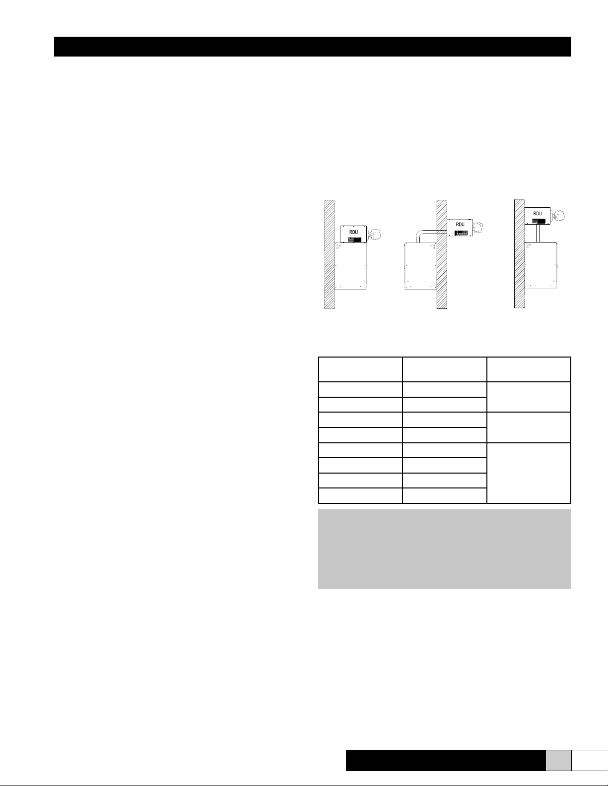
The RDU may be directly mounted on top of the Herrtronic
cabinet or mounted remotely. The RDU consists of a fan,
controls, & steam hose to distribute the steam directly into
the space. RDU-D must be remotely mounted when used
with an MDM series humidier.
Figure 1 - Mounting Options
Model No
RDU-D-1 208-240-1-50/60
RDU-D-1T 480-600-1-50/60
RDU-D-2 208-240-1-50/60
RDU-D-2T 480-600-1-50/60
Electrical
Characteristics
Capacity
5-50 lbs/hr.
60-100 lbs/hr.
RDU-D-2R 208-240-1-50/60
RDU-D-2L 208-240-1-50/60
RDU-D-2TR 480-600-1-50/60
110-250 lbs/hr.
RDU-D-2TL 480-600-1-50/60
Note: 1T & 2T models include a transformer to provide
208/230 single phase power to the RDU.
Note: MDD Units require two RDU units. For Direct
Mount you must use a specic right and left mount unit.
For remote mount, two Identical units may be used.
Herrtronic® RDU-D Supplement
For remote mounting applications, the plumbing and
electrical connections may be routed through the bottom
or back of the RDU. There are two electrical knockouts,
two steam supply knockouts and one condensate return
knockout on both the bottom and back to facilitate
installation.
www.trioniaq.com
3

Installation, Operation, & Maintenance Manual
10.05"
16.91"
15.40"
As shipped, the RDU is set up for direct unit mounting.
Longer wiring and condensate return tubing (supplied) will
be required for remote mounting. Be sure to use 18 gauge
(minimum) copper conductor wire with insulation rated for
600 VAC. Supply power may originate from the Herrtronic
humidier or a separate supply. If a separate source is
used, be sure to install a dedicated power disconnect.
All hardware and accessory components required for
installation are included as listed below:
Accessory Bag Contents
Item Quantity
¾” I.D. Plastic bushing 2
3” Diameter plastic hole plug 2
5/16” I.D. Plastic bushing 1
Steam inlet union 1*
2 ½” Stainless steel hose clamp 1*
¼” x 2” Lag screw 2
#8–32 x 3/8” Stainless steel machine screw 4
Wiring Kit
¼” O.D. Condensate return tubing
1
10’
*-Double quantity for RDU-D-2 series units
III. INSTALLATION PREPARATION
! WARNING !
Disconnect power to the humidier while
installing RDU.
The RDU unit must either be placed higher than the
Herrtronic unit or provisions for handling the condensate
via an external drain must be made. The following chart
details the physical clearances around the cabinet for
servicing the unit. Figure 13 details the clearances required
due to the steam plume.
MINIMUM CLEARANCES AROUND CABINET
LEFT - 15”
RIGHT - 15”
TOP* - 2”
BOTTOM - 0”
* Subject to output, fan speed and room conditions
NOTE:
The steam plume should not impinge on walls,
ceilings or other objects. Supply air registers, if
present, must be directed away from RDU.
Figure 2 - Overall Dimensions
1.20"
.56"
3.00"
(4) 7/8" Holes
Power Access
(2) 7/8" Holes
Optional Condensate Drain
Figure 3 - Bottom View Dimensions
2.25"
(4) 7/8" Knockouts
Power Access
3.00"
1.00"
.92"
2.39"
4.08"
5.71"
7.06" 4.00"
4.92"
.92"
Front of Unit
12.00"
12.70"
2.39"
.50"
7.70"
(2) 3" Holes
Steam Hose Inlet
(2) 5/16 X 5/8 Dia.
Keyhole Mounting Slots
(2) 2 1/2" Holes
Optional Steam Inlets
2.00"
4 www.trioniaq.com
Figure 4 - Back View Dimensions
Herrtronic® RDU-D Supplement
Installation, Operation, & Maintenance Manual
SIDE
REMOVE THE COVER FROM THE RDU
1. Loosen the two hex socket head set screws on the fan
speed control knob and remove knob (Figure 5).
2. Remove the phillips head screws which fasten the
cover to the housing.
Figure 5
PHILLIPS HEAD SCREWS
(6) PER SIDE
(1) ON FRONT
Fan Speed Control Knob
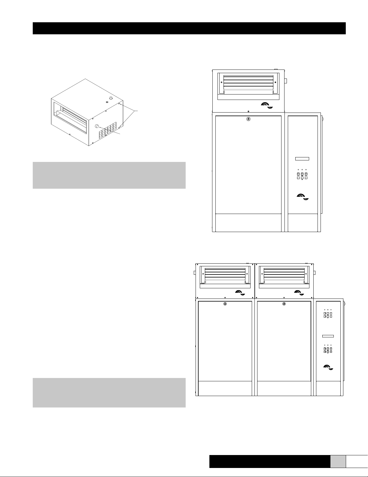
IV. DIRECT MOUNT OPTION (MDS, MDD)(Figure 6 & 7)
! WARNING!
Be sure to disconnect power to the Herrtronic
Humidier before beginning installation.
1. Assure that the mounting for the Herrtronic unit will
support the additional 40 pound load of each RDU
unit.
2. Remove the knock-out from the top of the Herrtronic
cabinet and install the 5/16” I.D. plastic bushing for the
condensate return.
3. Remove the rearmost 7/8” knockout from the top of
the Herrtronic cabinet.
4. Install one 3/4” plasitc bushing from the inside into the
rearmost 7/8” hole in the bottom of the RDU.
5. Place the RDU on the Herrtronic cabinet, guiding the
steam hose(s) into the tank compartment.
6. Feed the wires (total of seven) through the 3/4” bushing
and condensate tubing through the 5/16” bushing into
the Herrtronic unit.
7. Fasten the RDU in place using four #8-32 self-tapping
screws installed from inside the Herrtronic cabinet.
8. Replace the RDU cover & fan speed control knob.
9. Insert the condensate return tubing into the grey
plastic ll tee. It will extend I” into the tee.
10. Connect wires # 1 -6 to the 6 pole RDU terminal strip
located near the top of the Herrtronic high voltage
electrical compartment. Connect the ground wire #24
to the Herrtronic ground terminal located near the
bottom of the high voltage compartment.
Installation is now complete. Proceed to the RDU Operation
section of this manual then to the Start-Up section of the
Herrtronic Installation and Operation Manual OM-93.
HERRMIDIFIER
CYL FULL
FAULTPOWER
ON/OFF
BACK
ENTERFAULTS
HERRTRONIC MD
HERRMIDIFIER
Figure 6 - MDS Direct Mount
HERRMIDIFIER
HERRMIDIFIER
SLAVE
CYL FULL
ON/OFF
FAULTS
MASTER
CYL FULL
ON/OFF
FAULTS
HERRTRONIC MD
HERRMIDIFIER
FAULTPOWER
BACK
ENTER
FAULTPOWER
BACK
ENTER
NOTE
See Figure 15, 16 & 17 for standard electrical hookup
for MDM and MDS.
11. Remove jumper wire #39 from the Herrtronic 12
pole controls terminal strip located in the low voltage
electrical compartment between poles #1 and #2.
Herrtronic® RDU-D Supplement
Figure 7 - MDD Direct Mount
www.trioniaq.com
5
 Loading...