

Page 1
Notice to Contractor:
Once installation is complete, please
leave this manual with the customer
for future reference.
READ AND SAVE THESE INSTRUCTIONS
Comfort
STEAM
Humidication System
Trion® | www.trioniaq.com
TM
Page 2
Installation, Operation, & Maintenance Manual
COMFORTSTEAM
READ AND SAVE THESE INSTRUCTIONS
LIRE ET CONSERVER CES INSTRUCTIONS
TABLE OF CONTENTS
HOMEOWNER SECTION
1. Warranty Statement .................................................................................................................................3
2. Safety Warnings .......................................................................................................................................3
3. Warnings and Disclaimer .........................................................................................................................4
4. Homeowner Instructions and User Manual .............................................................................................. 4
5. Start-Up .................................................................................................................................................... 5
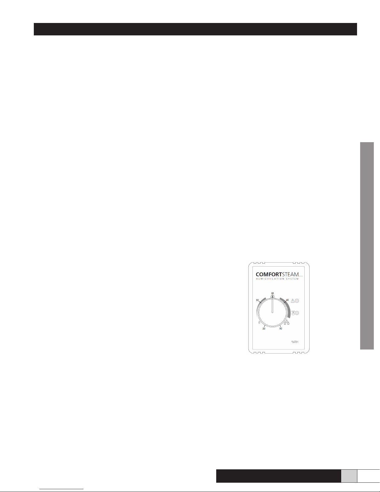
6. How to Control the Humidity ....................................................................................................................5
7. Functions of the Electronic Circuit ...........................................................................................................6
8. What to do if a Malfunction Occurs .......................................................................................................... 7
9. Description of Error Codes .......................................................................................................................7
10. Cleaning the Tank ....................................................................................................................................8
11. Preventative Maintenance .......................................................................................................................9
CONTRACTOR INSTRUCTIONS SECTION
12. Unpacking the Unit ................................................................................................................................... 10
13. Dimensions and Available Models ...........................................................................................................11
14. Detailed View of Wiring ............................................................................................................................ 12
15. Installing the Steam Hose and the Steam Diffuser ................................................................................. 14
16. Installing the Humidier ........................................................................................................................... 16
17. Installing the Water Supply ...................................................................................................................... 18
18. Installing the Air Pressure Probe ..............................................................................................................19
19. Making Electrical Connections ................................................................................................................. 20
20. Installing and Connecting the Humidistat ................................................................................................. 20
21. Start-up and Test Procedure ....................................................................................................................21
22. Wiring Diagrams ...................................................................................................................................... 22
2 www.trioniaq.com
Comfort
STEAM
TM
Page 3
Installation, Operation, & Maintenance Manual
1. Warranty
Humidier 5-Year Limited Warranty
This limited warranty covers Trion Residential Type Humidiers,
excluding duct work, wiring and installation. Trion warrants that all new
Trion humidiers are free from defects in material and workmanship
under normal, non-commercial use and service. Trion will remedy any
covered defects if they appear within 60 months from the date of original
installation & subject to the terms and conditions of this Limited 5-Year
Warranty stated below:
1. THIS LIMITED 5-YEAR WARRANTY is granted by Trion Customer
Service, 101 McNeill Road, Sanford, NC 27330.
2. This warranty shall extend only to any non-commercial owner who
has purchased the residential humidier other than for purposes
of resale.
3. All components are covered by this limited warranty except
expendable items, such as evaporative pads, media lter pads
and nozzles.
4. If, within the warranty period, any Trion residential humidier unit or
component requires service it must be performed by a competent
heating and/or air conditioning contractor (preferably the installing
contractor). Trion will not pay shipping charges, or labor charges
to remove or replace such defective parts or components. If the
part or component is found by inspection to contain such defective
material and workmanship it will be either repaired or exchanged
free of charge at Trion’s option, and returned freight collect.
5. In order to obtain the benets of this limited 5-year warranty, the
owner must notify the dealer or distributor of any defect within 30
days of its discovery. If after reasonable time you have not received
an adequate response from the dealer or distributor, notify in
writing to Trion Customer Service 101 McNeill Road, Sanford, NC
27330, or call 1-800-884-0002 or email customerservice@trioniaq.
com Humidiers which have been installed or become part of real
estate cannot be returned. Trion will receive, freight prepaid, only
removable parts or components of such defective humidiers.
6. This limited warranty does not apply to any part or component
that is damaged in transit or in handling, has been subject to
misuse, neglect or accident; has not been installed, operated
and serviced according to Trion’s instructions; has been operated
beyond the factory rated capacity; or altered in any such way that
its performance is affected. There is no warranty due to neglect,
alteration or ordinary wear and tear. Trion’s liability is limited to
replacement of defective parts or components and does not include
the payment of the cost of labor charges to remove or replace such
defective components or parts.
7. Trion will not be responsible for loss of use of any product;
loss of time, inconvenience, or any other indirect, incidental or
consequential damages with respect to person or property, whether
as a result of breach of warranty, neglect or otherwise. SOME
STATES DO NOT ALLOW THE EXCLUSION OR LIMITATION
OF INCIDENTAL OR CONSEQUENTIAL DAMAGES, SO THE
LIMITATION OR EXCLUSION IN THE PRECEDING SENTENCE
MAY NOT APPLY TO YOU.
8. THIS WARRANTY GIVES YOU SPECIFIC RIGHTS, AND YOU
MAY ALSO HAVE OTHER RIGHTS WHICH VARY FROM STATE
TO STATE.
9. Any warranty by Trion of merchantability, tness for use or any
other warranty (express, implied or statutory), representation or
guarantee other than those set forth herein, shall expire at the
expiration date of this express limited warranty. SOME STATES
DO NOT ALLOW LIMITATIONS ON HOW LONG AN IMPLIED
WARRANTY LASTS, SO THE LIMITATION IN THE PRECEDING
SENTENCE MAY NOT APPLY TO YOU.
10. Trion reserves the right to make changes in the design and material
of its products without incurring any obligation to incorporate such
changes in units completed on the effective date of such change.
2. Safety & Warnings
!
DANGER
RISK OF ELECTRIC SHOCK
Before cleaning, servicing, or parts replacement, the unit must
be disconnected from all sources of electricity.
!
WARNING
Improper installation, adjustment, alteration, service, or main-
tenance may cause property damage, injury, or death. This
appliance must be installed according to these instructions.
Read these instructions thoroughly before installing or servic-
ing the unit.
!
CAUTION
Read these instructions thoroughly before installing this unit.
Check data label and verify electrical specications agree
with those at the point of installation.
!
WARNING
Failure to install this unit in a position that is level and plumb
may impair the unit’s ability to drain if an overow condition
presents itself. Damage to personal property may also result.
!
WARNING
Installation in freezing conditions can result in unit failure.
Damage to personal property may also result.
!
WARNING
A drain safety pan should be installed under the unit and any
supply water / drain connections to prevent damage to prop-
erty in the event of a water leak or faulty operation.
!
CAUTION
Trion recommends that this humidier be installed by a
trained HVAC professional. Do not connect the unit to the
power source until the installation is complete. A thorough
checkout of the unit installation should be completed before
operating the unit. Failure to follow these directions may void
the manufacturer’s original warranty.
!
WARNING
Electrical power to the furnace must be disconnected before
proceeding. Serious injury or death may result.
Comfort
STEAM
TM
www.trioniaq.com
3
Page 4
Installation, Operation, & Maintenance Manual
HOMEOWNER / CONTRACTOR
3. Warnings and Disclaimer
Please read and understand the warnings and instructions
fully before you begin this installation and keep them for future
reference.
The manufacturer will assume no responsibility and the warranty
will be void if the installer or the user does not adhere to the
following precautions:
1. This humidier will be connected to and used under water
pressure and it must be installed in such a way that if
a leak occurs, the water could not cause any damage to
the property. Make sure all water connections are properly
installed or a water leak could occur.
2. This humidier is intended for use on forced warm air
circulation furnaces, as well as multi-fuel furnaces, which
have, at least, one supply duct connected to the furnace and
where a positive air pressure can be measured.
3. Do not install a humidier where the surrounding temperature
may be 32ºF (0ºC) or colder. Freezing water will damage
the humidier and may burst the supply line, resulting in
property damage.
4. Do not install the humidier directly on the furnace housing.
5. Always check that you are not about to cut or drill into an air
conditioning coil or electrical accessory during installation.
6. Do not install a humidier if the city water pressure exceeds
90 psi. Check the local codes related to pressure reduction.
7. Do not install the steam delivery stub or steam diffuser in
the supply duct if the pressure exceeds 0.5” Water Column
(0.125 kPa).
8. The installation, wiring and plumbing of the humidier must
comply with national, state and local electrical, plumbing
and building codes.
9. Electrical wiring and water lines must not come in contact
with sharp edges or hot surfaces.
10. Make certain an appropriate drain system is installed and
there is no resistance to the ow of the discharged water.
11. Do not set the humidity level higher than that recommended
or condensation damage will occur.
12. Please beware of sharp edges when you cut into a metal
duct.
13. Always shut the power off before you start the installation or
when doing maintenance. An electric shock from 120 or 240
volts could cause serious injury or death.
14. When you perform maintenance, please be careful because
the unit can be extremely hot. Always allow enough time for
the unit to cool down.
15. To prevent electric shock or injuries, never operate the
humidier without the cover as there are high voltage and
high temperatur components inside.
16. This humidier will only work with standard potable water,
not with technical water. The maximum water supply
temperature is 86 ºF (30 ºC).
4. Homeowner Instructions and User Manual
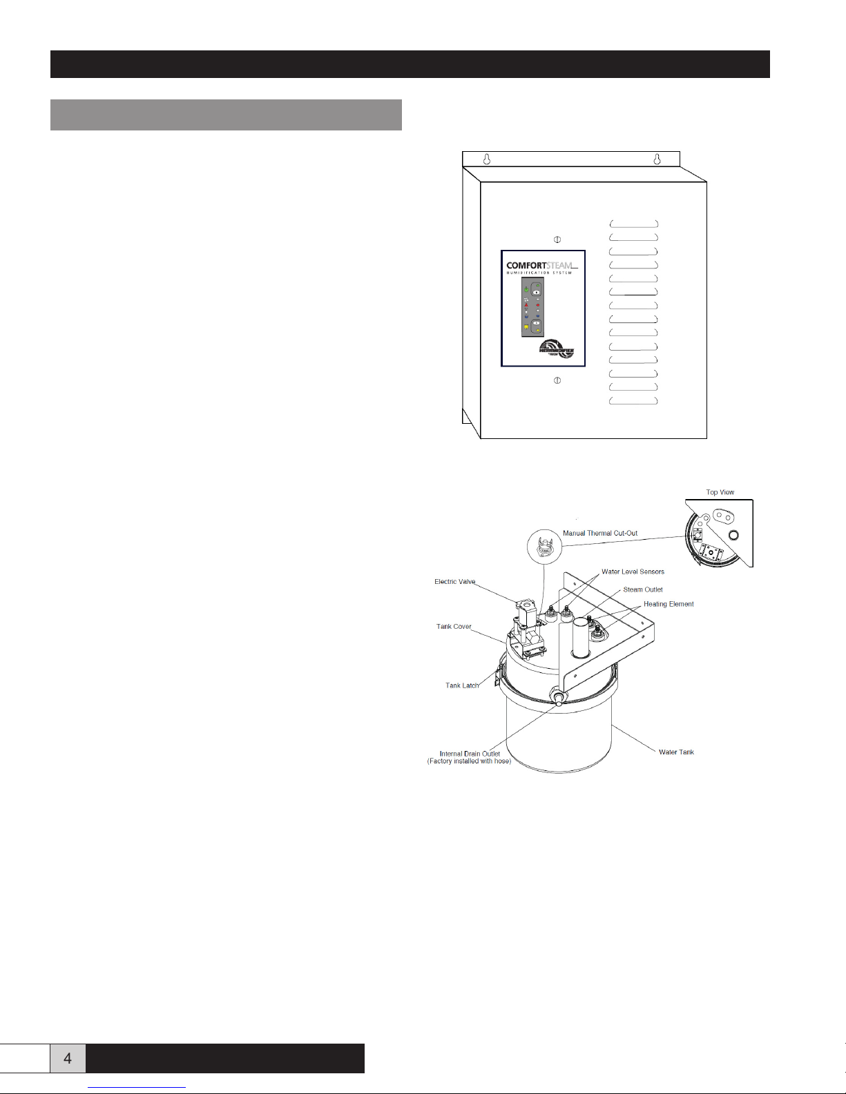
Figure 1 - External View
Figure 2 - Top and Side View
4 www.trioniaq.com
Comfort
STEAM
TM
Page 5
Installation, Operation, & Maintenance Manual
5. Start Up
The startup of the humidier is done as follows:
• Put the main power ON at the electrical panel. The green
pilot light comes ON. The humidier is ready to work.
• Open the water supply valve.
• Adjust the knob on the humidistat.
Note: The humidier may perform a ush cycle prior to producing
humidity. If the yellow drain LED is lit and the unit appears not
to be operating properly, allow the unit at least 15 minutes to
begin normal operation. This is considered normal as the control
system ensures that all systems are stable before operation.
Working Principle:
• Unlike other types of humidiers which produce humidity
by passing warm air on a water curtain, a rotating pad or
another type of media, this humidier produces humidity
from steam dispersed directly into the supply duct.
• A humidistat (installed either on the wall or the air return
duct) controls the unit. Adjust the setpoint of the humidistat
according to your need or comfort. Please read the next
section about the humidity control.
• When the humidistat senses a need for humidity, it starts the
humidication process.
• The tank lls with water.
• The electronic control starts the fan in the furnace to move
the air as the humidier starts boiling water and producing
steam. If the fan cannot start (i.e. there is no air movement
to transport the steam or insufcient air pressure), the
humidier stops itself. Please note that it may take a few
minutes to bring the water to a boil. The steam exits the
water tank through the steam hose, moves to the steam
delivery tube installed in the warm air duct and is released
into the duct where it mixes with the moving air.
• As water evaporates, the electric valve opens as needed to
replenish the water in the tank.
• When the humidity reaches the desired level, the humidier
stops producing steam. In order to eliminate the residues
and keep the tank as clean as possible, the humidier also
drains after a certain number of boiling / rell cycles. This
is determined by the DIP switches on the lower right corner
of the electronic control board. If there is still a demand
from the humidistat after draining, the tank rells and starts
to produce steam again. This process is part of the selfcleaning feature.
• When the humidistat is satised, the fan continues to run for
a short period of time in order to eliminate the steam from
the ducts and the unit goes to ready mode, waiting for the
next call from the humidistat.
6. How to control the humidity
Humidity between 35-40% is desirable. However, you should
take the outside temperature into consideration before setting
the humidity level in order to avoid condensation on the windows.
If you installed a ComfortSteam humidistat and an outdoor sensor,
a setpoint adjustment will be done automatically as the outdoor
temperature falls. The outdoor sensor reduces the setting of the
humidistat according to the outdoor temperature during cold
days without having to set the humidistat knob manually.
It does the opposite during mild days. Please see the below table
for the percentage of relative humidity on the electronic humidistat
label. The middle of the scale corresponds to the middle of the
comfort zone, approximately 35% RH (Relative Humidity).
If you are using a mechanical or other humidistat, the adjustment
according to the outside temperature will have to be done
manually. For your information, the following table shows the
recommended setting of the humidistat according to the outside
temperature. Please see Fig. 3.
Outside Temp Recommended Setting
-22°F (-30°C) 15%
-13°F (-25°C) 20%
-4°F (-20°C) 25%
+5°F (-30°C) 30%
+14°F (-10°C) 35%
above:
+23°F (-5°C) 40%
Figure 3
No matter which humidistat system you are using, please
be aware that the humidity level cannot adjust quickly. It may
take some time to build up the humidity to your comfort level.
Depending on the dryness of the house, carpets, furniture,
drapes and wood will absorb moisture before you can feel the
change.
HOMEOWNER
Comfort
STEAM
TM
If the house remains unoccupied during the winter season,
set the humidistat to the minimum set point in order to prevent
condensation.
www.trioniaq.com
5
Page 6
Installation, Operation, & Maintenance Manual
7. Functions of the Electronic Circuit
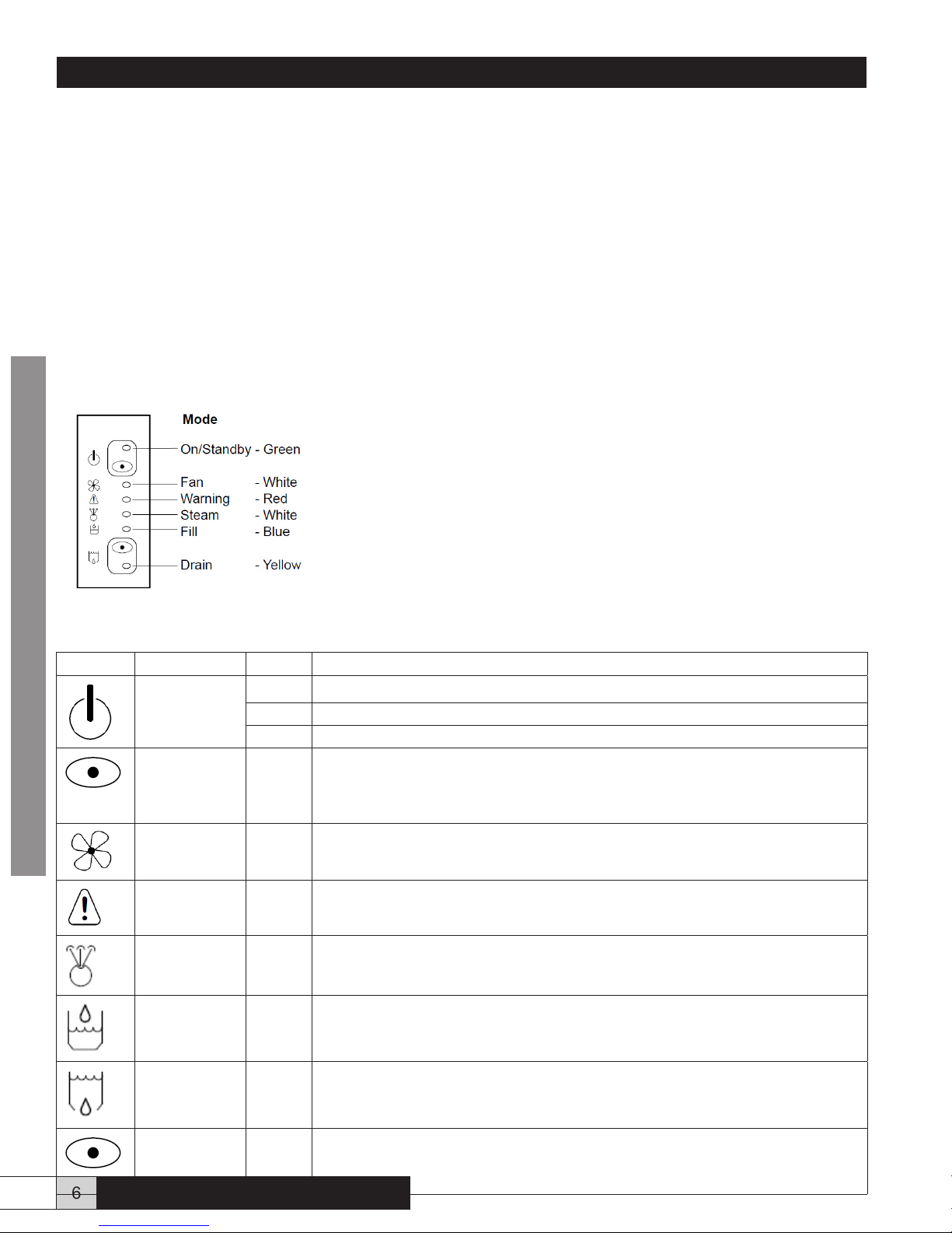
The electronic board located inside the unit controls all the humidier functions. The front panel is equipped with pilot lights indicating
the status of the humidier. Please see Fig. 5. Please see below for a reference to the description of the functions.
The red pilot light, which is a warning light, can either glow all the time or ash when activated.
In case of error, the humidier enters stand-by mode. The ashing of the pilot lights indicates which error happened. The error
recognition sequence is as follows:
• The green pilot light near the power button blinks once;
• The red light ashes a certain number of times, this is the error code;
• A pause with no light at all;
• Another blink of the green light, once;
• Another series of ashing of the red light;
• And so on until the condition is reset or service is performed. Shutting the power OFF at the breaker in the main panel or
depressing the power button until the green light is fully on will reset the error code.
The COMFORTSTEAM humidistat also has two pilot lights to indicate the current status.
The green light is lit when the humidistat is demanding for humidity, thus activating the
boiling cycle. The red light indicates a warning and reproduces the same warning code
as the red light on the humidier control panel. If ever the red light is lit or ashing on the
humidistat, you know immediately that the humidier needs attention.
Figure 5 - Modes
Icon Display Status Description
HOMEOWNER
On/Standby
Green Light
White
Button
Fan
White Light
Warning
Red Light
Steam
White Light
Filling Cycle
Blue Light
OFF The humidier has no power – Breaker is OFF.
Blinking The humidier has power, but is in standby mode.
ON The humidier has power and is functional.
Press to put the humidier in stand-by mode.
The green light is blinking.
Press and keep depressed 3 seconds to power or reset the humidier. The green light
is ON.
ON The fan control is activated.
ON An abnormal condition occurred.
Please refer to the error code table in Section 7.
ON The humidier is heating water to produce steam.
ON The electric water valve is open thus lling the humidier.
Draining Cycle
Yellow Light
White Button ON Not active on residential models.
ON The humidier is in draining mode.
6 www.trioniaq.com
Comfort
STEAM
TM
Page 7
Installation, Operation, & Maintenance Manual
8. What to do if a malfunction occurs
• Shut the main power OFF and restart the humidier to see if the error code disappears.
• If you see a water leak, follow the water supply tube and close the valve installed on the water pipe located near the humidier.
• Please refer to the error code table to identify the possible cause of the malfunction and the actions that you can take.
• Should the problem persist, please call your service company. They are the best qualied to help you quickly. Describe the
problem to them and mention the error code you observed on the front panel. They may help you solve the problem over the
phone. If needed, they will x the problem themselves or call our technical service.
• Should you attempt to look at the unit yourself, please apply all appropriate safety measures. - Shut the main power OFF and
wait for the unit to cool before you open it.
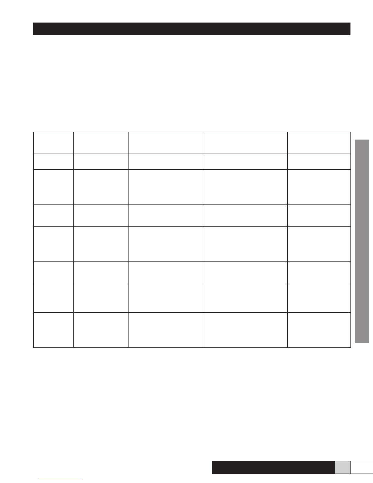
9. Description of error codes
Number of
ashes of the
red light
OFF No error The humidier is working
Continuous ONThere is water in the
1 Problem with the
2 Inadequate water
4 Inadequate
5 Not enough air ow
6 Temperature inside
Error Description Humidier Status Actions to be taken by the
ne
Risk of overow. Humidier
pan under the tank.
water level sensors
inside the unit.
supply.
drainage.
or pressure in the
supply duct
the tank exceeded
the high temperature
limit and the safety
switch has tripped.
stops itself.
Internal problem - Humidier
cannot read the water level
properly and stops itself.
Humidier cannot ll
properly and stops itself
- Heating elements and
supply valve are switched
off.
Humidier cannot drain
properly - Risk of overow the unit stops itself.
Humidier stops itself. Turn the main power OFF,
This is a very serious
condition. The humidier
stops itself and cannot start
without service.
Owner
None
Turn the main power OFF, then
- Open the unit and check for
leaks - Check the drain tube Close the supply valve and call
for service
Turn the main power OFF, then
call your service company.
Turn the main power OFF,
then - Check the water supply
circuit - Check if the water
supply valve is open. - Call your
service company
Turn the main power OFF, then
- Close the supply valve - Call
your service company.
then - Check the air lter in the
furnace. It may be clogged up Call your service company.
Turn the main power OFF, then
call your service company
Reset
Automatic Reset when
switching main power
ON again.
Automatic Reset when
switching main power
ON again.
Automatic Reset when
switching main power
ON again.
Automatic Reset when
switching main power
ON again.
Automatic Reset
when error conditions
disappear.
Only the service
company can reset the
unit after checking all
functions.
HOMEOWNER
Comfort
STEAM
TM
www.trioniaq.com
7
Page 8
Installation, Operation, & Maintenance Manual
10. Cleaning the tank
As with any device evaporating water, some minerals normally dissolved in the water may create deposits inside of the unit. Even
though the unit is draining and ushing itself during normal operation , it will require a bit of maintenance from time to time.
WARNING:
• The water tank and its contents can become extremely hot. Please be careful when you handle it.
• The tank may have water inside.
To drain the humidier, ensure that the humidistat is calling for humidity (You may have to adjust the setpoint higher to make this
happen), then cycle the main power and the unit will enter a drain cycle. It may take a few minutes for the tank to begin lling as
it needs to do to envoke the siphon draining system. Once the unit is drained, there will be approximately one inch of water in the
bottom of the tank. At this time the main power should be turned off and the unit should be allowed to cool.
Wait until the unit has cooled before proceeding with the following steps.
1. Before proceeding, ensure the main power is OFF.
2. Remove the cover by turning the two 1/4 turn screws to the left.
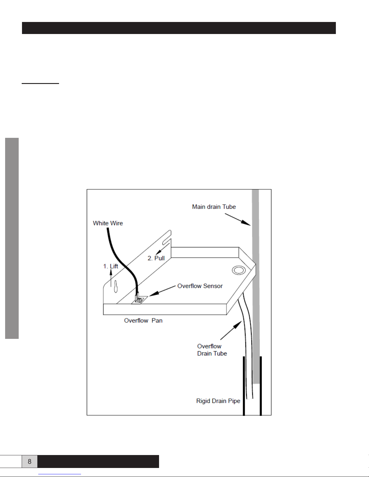
3. Unplug the white quick connect wire connected on the water pan at the bottom of the unit. This wire is connected to the overow
sensor. Please see Fig.6
HOMEOWNER
Figure 6
8 www.trioniaq.com
Comfort
STEAM
TM
Page 9
Installation, Operation, & Maintenance Manual
10. Cleaning the tank continued
4. Pull the plastic tube attached to the bottom of the unit out of the rigid drain pipe on the wall. You do not have to remove the plastic
tube attached to the bottom of the pan. Remove the overow pan from the unit by slightly loosening the front screw then lifting
the front of the pan off the screw and pulling it towards you. Please see Fig. 6. Remove the main drain tube from the rigid drain
pipe attached to the wall and check that they are both clean and clear from deposits.
5. Check that the water tank is not too hot to handle. Unfasten the latch around the water tank and remove the tank from the main
body of the humidier by pulling it down. When you remove the tank, it is possible to clean the round o-ring gasket, but don’t
discard it.
NOTE :This round gasket is mandatory and the unit will not work properly without it.
6. Soap or vinegar can be used to clean the water tank, the heating element and the tips of the level sensors. Other cleaning
products used to remove scale, lime or calcium are also available on the market, but DO NOT use a metal brush or any strong
acids to clean the tank as they may damage the stainless steel.
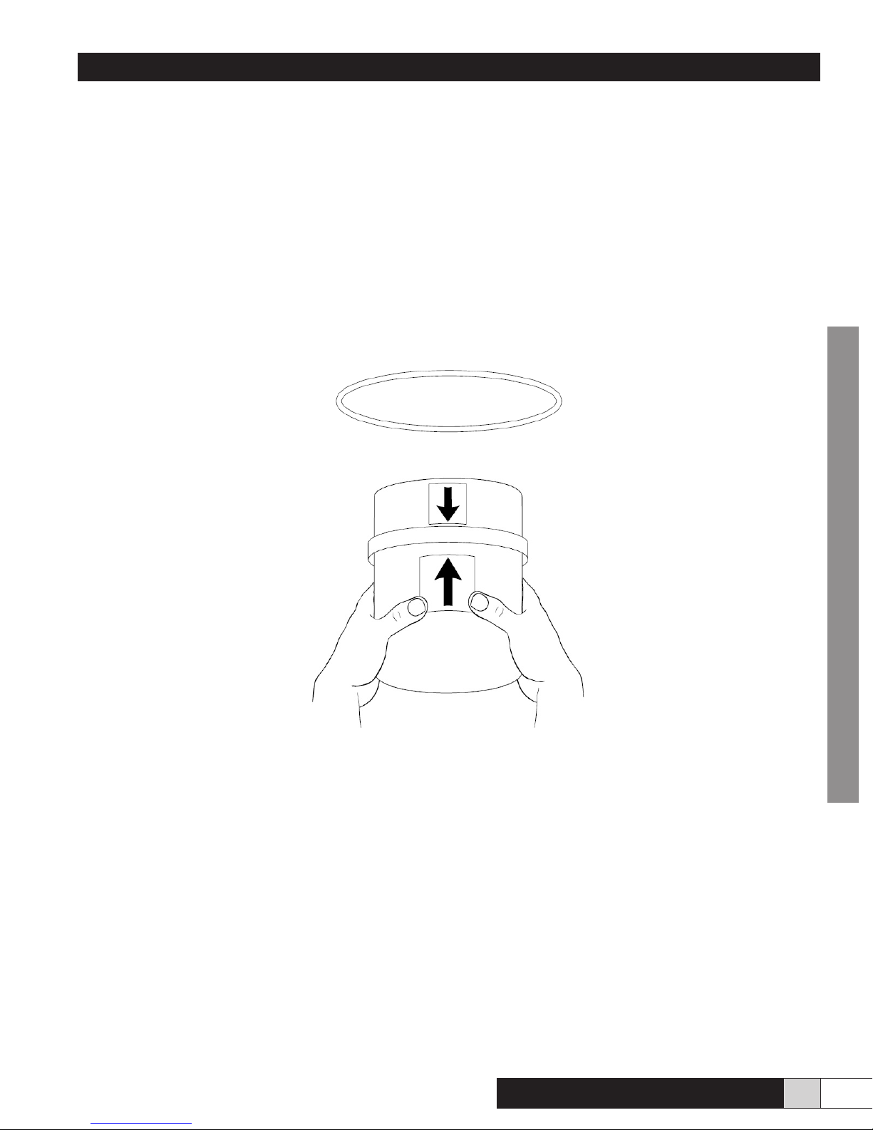
4. Once completed, reinstall the round gasket around the water tank collar. Please see Fig. 7. Align the two arrows located at the
front of the tank and the xed part while lifting the tank in place. Please see Fig.8. Apply even pressure to secure the tank properly
in the top part. Then close the latch holding the tank in position. Verify that the o-ring gasket and tank are seated properly.
Figure 7
Figure 8
5. Put the overow pan under the tank by sitting it back on its holding screws.
6. Reconnect the white wire of the overow sensor on the water pan.
7. Put the overow and main drain tubes back into the rigid drain pipe attached to the wall.
8. Put the cover back on the humidier and lock it with the two quarter-turn screws.
9. when nished, turn the main power back “ON” and readjust the humidistat to it’s previous setpoint.
11. Preventative Maintenance
Preventive maintenance to be performed every two years.
HOMEOWNER
In order to avoid problems due to accumulation of deposits, we suggest that you replace the centre metal tube, the silicone drain tube
and the low level sensor. We also suggest you replace the round o-ring gasket around the tank. All these components are available
in a tune-up kit.
To prepare for the Summer Season
• Shut the main power OFF
• Shut the water supply valve
• Perform a complete maintenance as described in section 8
• Dry the inside of the tank
Comfort
STEAM
TM
www.trioniaq.com
9
Page 10
Installation, Operation, & Maintenance Manual
12. Unpacking the Unit
Contents:
Please inspect the carton’s contents and report any missing parts or damage immediately.
1 Steam Humidier Unit
1 Main Drain tube (32” long – already installed and coiled inside the unit)
1 Steam hose (2 feet or 4 feet long x 1 inch I.D.) -depending on model
1 Steam delivery tube (6” L) or diffuser (12”, 15” or 19” L, depending on the humidier model)
1 Instruction and maintenance manual
1 Plastic bag containing installation material and hardware as follows:
2 Adjustable hose clips for the steam hose
1 Water hammer absorber (Red rubber hose with two brass ttings) Not supplied with model CFS-05B
1 Small bag - KIT #10S
1 Water supply tube (1/4” dia. x 7’ long)
1 Overow Drain tube for the pan (7/16” dia. x 24” long)
1 Pitot tube with plastic tube (5/16” dia. X 48” long)
NOTE : The electronic humidistat and the outdoor reset sensor are optional. They may be purchased separately. The humidistat can
be either wall type (RH) or duct type (DH).
CONTRACTOR
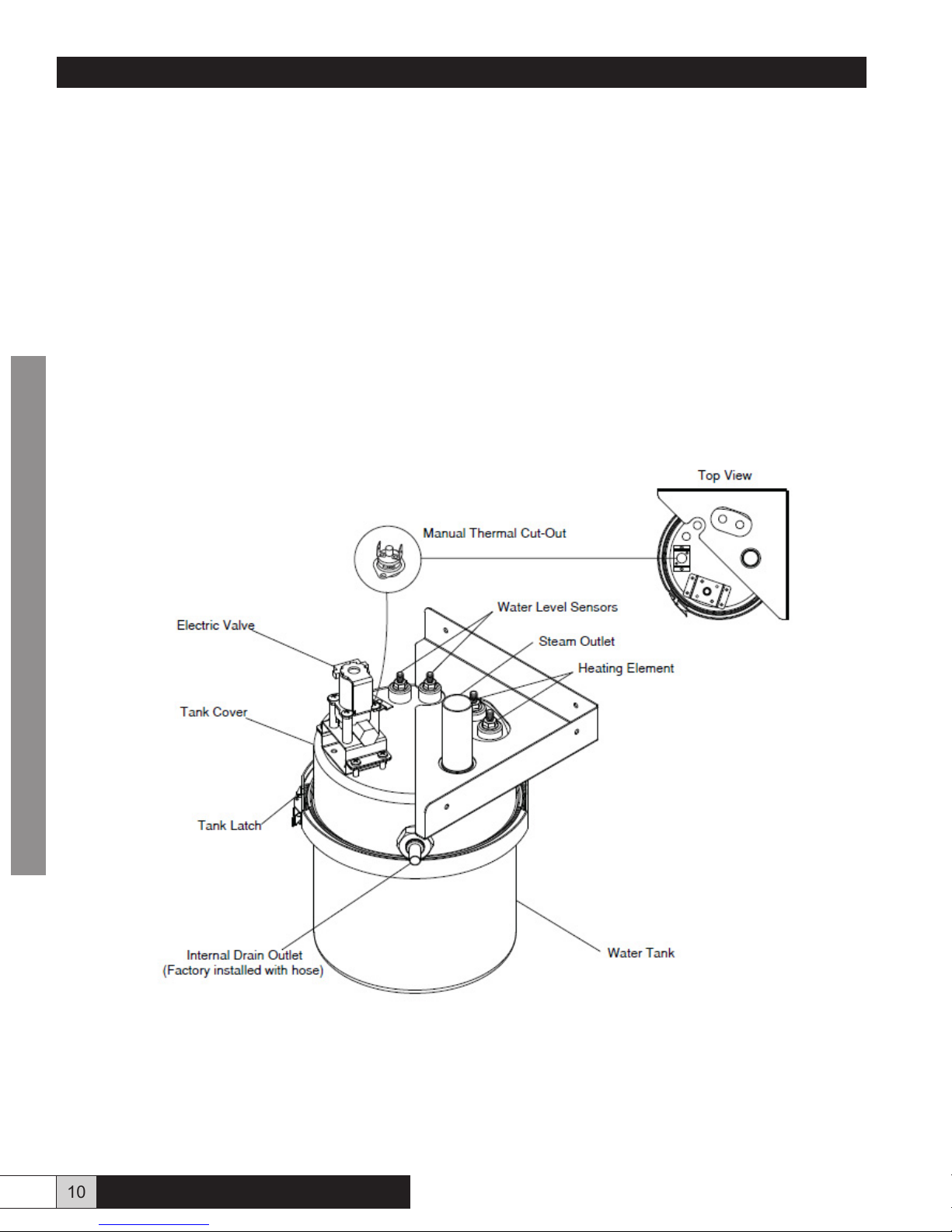
Figure 9 - Detailed Water Tank View
10 www.trioniaq.com
Comfort
STEAM
TM
Page 11
Installation, Operation, & Maintenance Manual
13. Dimensions and available models
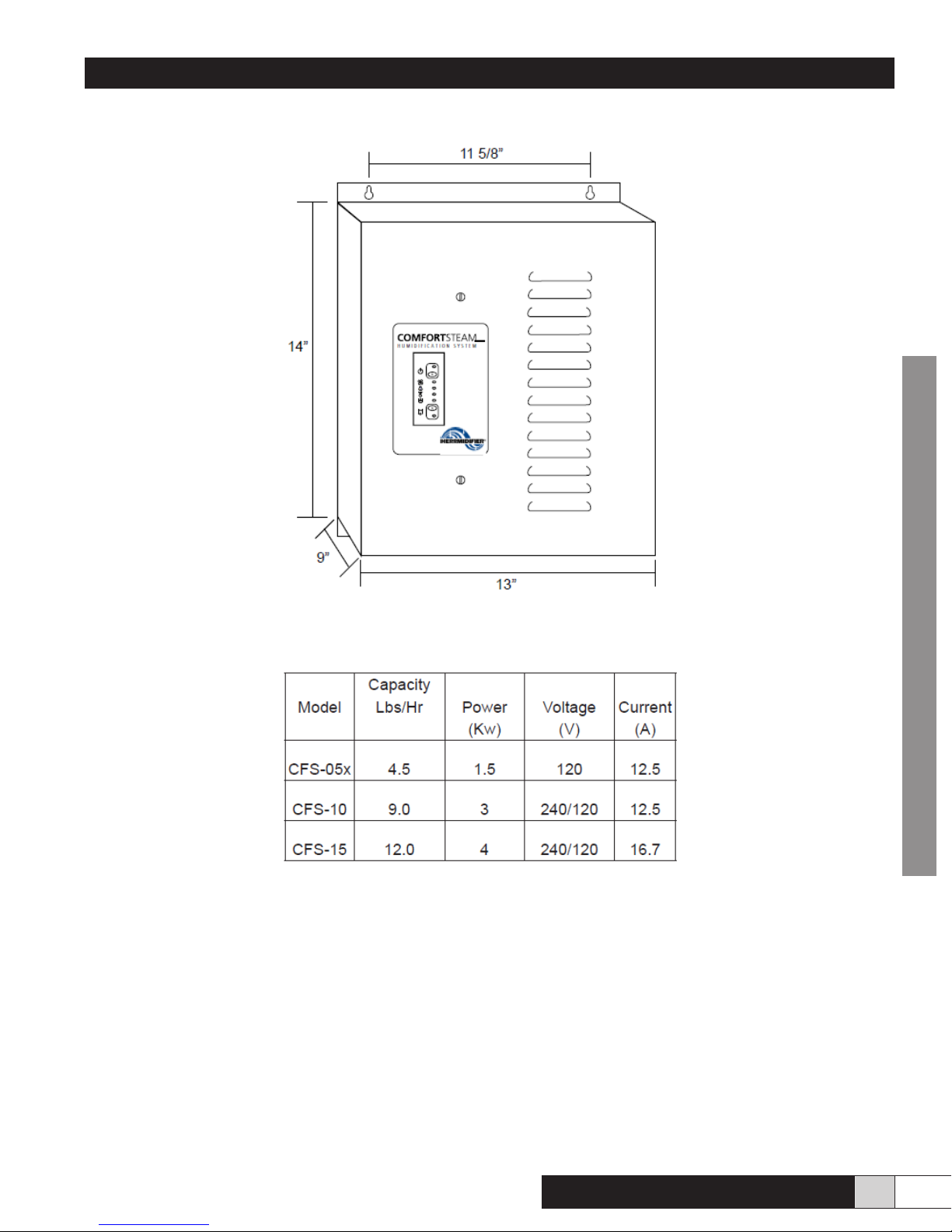
Figure 10 - Humidifer Dimensions
Figure 11 - Available Models
CONTRACTOR
Comfort
STEAM
TM
www.trioniaq.com
11
Page 12
Installation, Operation, & Maintenance Manual
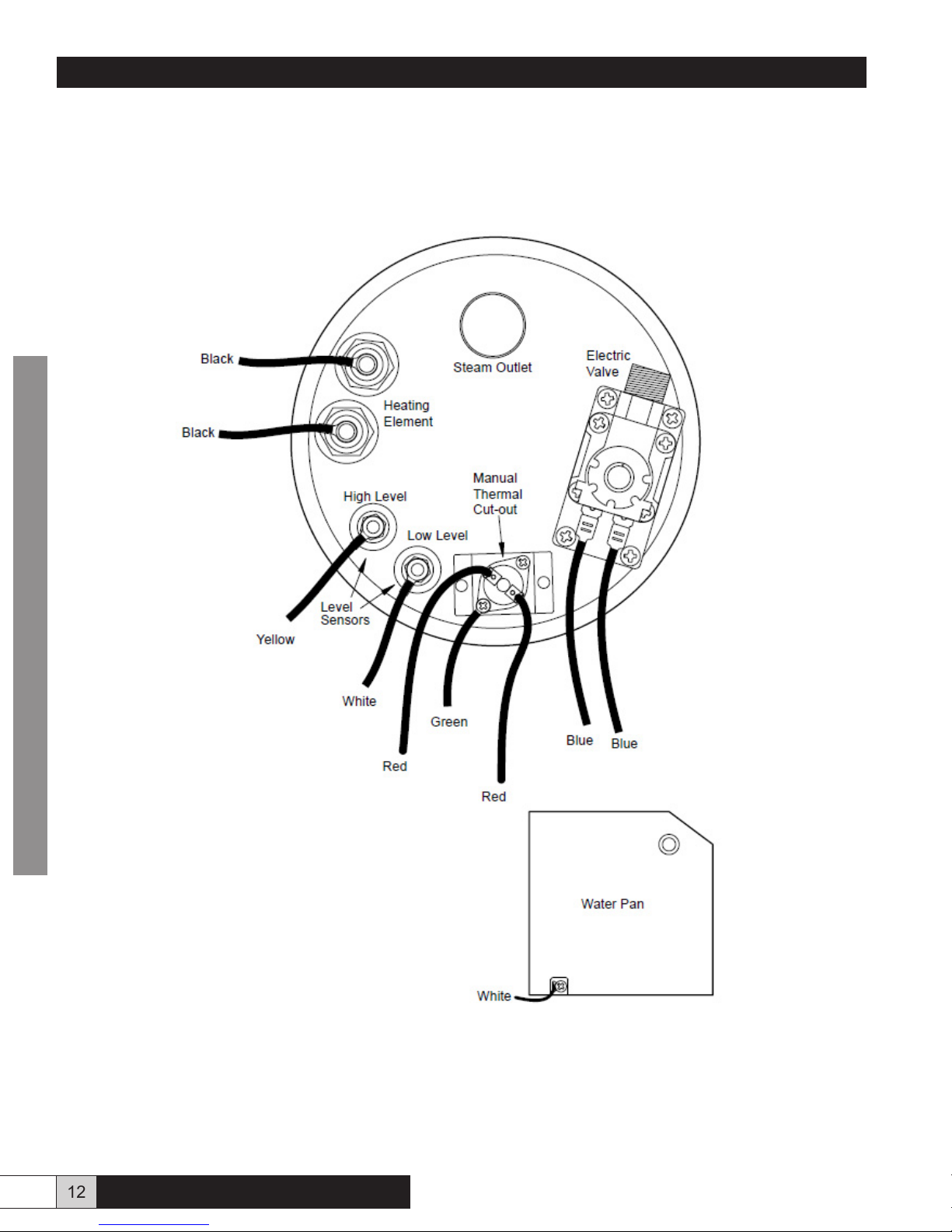
14. Detailed View of Wiring
CONTRACTOR
Figure 12 - Top of Unit
12 www.trioniaq.com
Comfort
STEAM
TM
Page 13
Installation, Operation, & Maintenance Manual
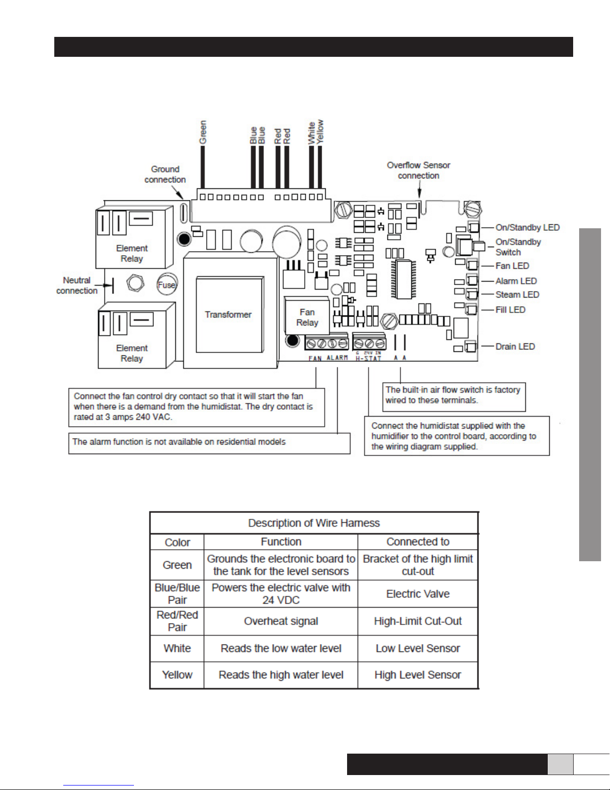
View and list of the wire harness by color and function.
CONTRACTOR
Comfort
STEAM
TM
www.trioniaq.com
13
Page 14
Installation, Operation, & Maintenance Manual
PLEASE READ SECTIONS 15 AND 16 BEFORE PROCEEDING.
15. Installing the Steam Hose and the Steam Diffuser
Proper installation of the steam delivery tube/diffuser and steam hose is critical for the troublefree operation of the humidier. Please
nd an accessible location on the duct and make sure you have a minimum length of 35” of straight duct downstream (without
elbows or other obstructions on which the steam could condense), to allow the steam to disperse easily into the airow. Once a
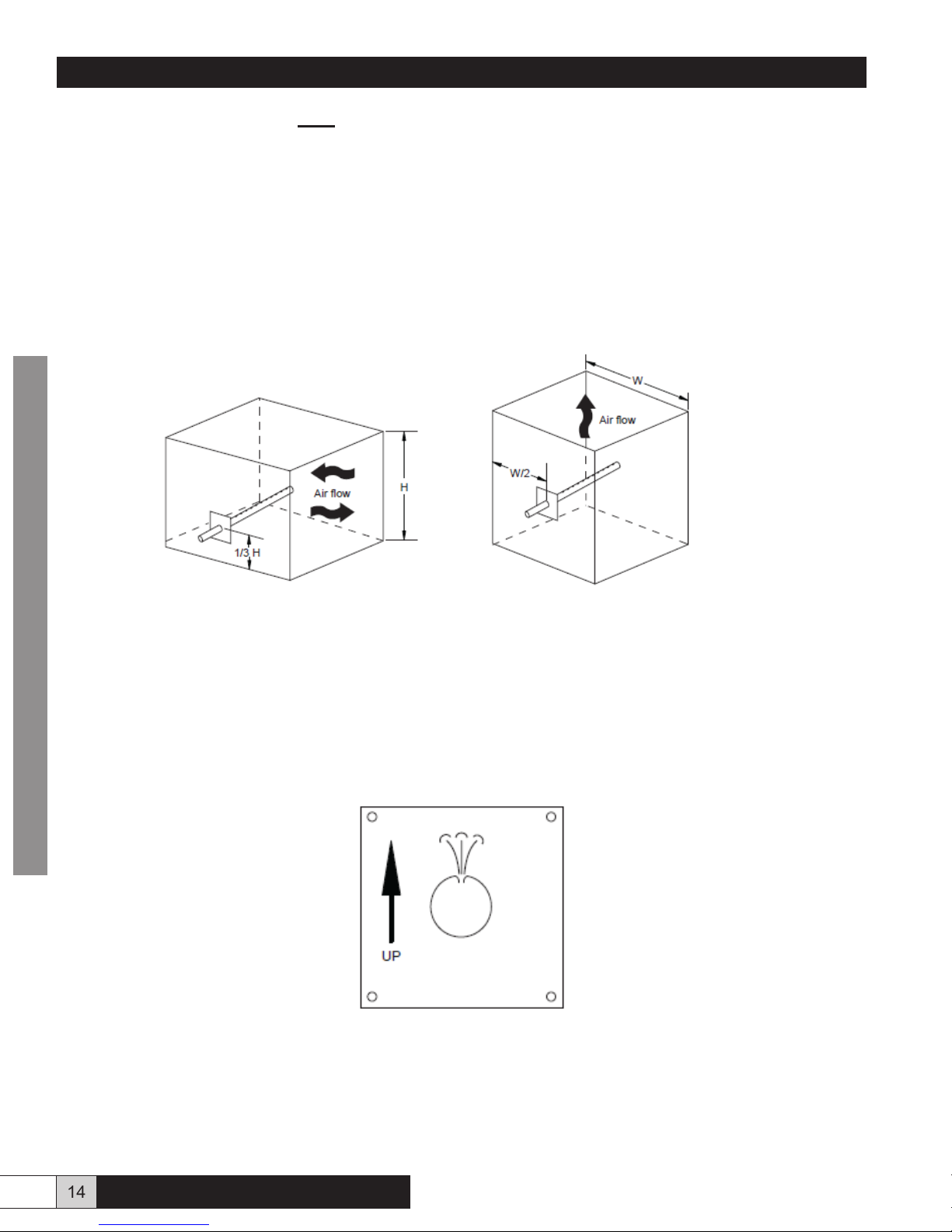
suitable location has been found make a 1 1/8” middle insertion hole in the warm air duct for the steam diffuser. For a horizontal duct,
make the 1 1/8” hole in the lower third of the duct height. Please see Fig. 13a. For a vertical duct, make the 1 1/8” hole in the middle
of the duct. Please see Fig. 13b.
Note: For High Velocity systems, the diffuser should be installed in the RETURN and not the warm air duct.
Figure 13a Figure 13b
Warning: Before installing anything on a duct, always check that you are not about to cut or drill into an air conditioning coil or
CONTRACTOR
electrical accessories.
• Insert the steam delivery tube/diffuser in duct and align arrow to point up. Fasten the steam diffuser to the duct using four #8 x
1/2” screws provided. in Kit #10S. Make sure the holes on the steam diffuser, where the steam exits from, are pointing up. Please
see Fig. 13c.
• Install one end of the steam hose onto the steam diffuser using a hose clamp and tighten it.
Figure 13c
14 www.trioniaq.com
Comfort
STEAM
TM
Page 15
Installation, Operation, & Maintenance Manual
PLEASE READ SECTIONS 14 AND 15 BEFORE PROCEEDING.
15. Installing the Steam Hose and the Steam Diffuser Continued
After installing the humidier (Section 15) use the second supplied hose clamp, to install the other end of the steam hose onto the
steam outlet on the top of the water tank and tighten it. Never try to reduce the diameter of the steam hose or any added rigid piping.
It has to be the same as the diameter of the humidier top steam outlet tting. The steam must ow without obstruction.
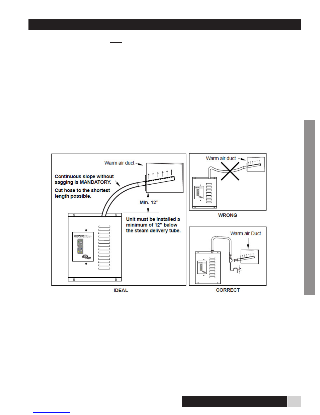
WARNING: Do not let the hose sag when it is connected to the duct. Please see Fig. 13d. A sufcient slope with no horizontal
section is mandatory to allow any condensation to ow back naturally to the water tank. Please see Fig. 14e. If condensation water
accumulates in the hose, the steam will not be able to escape normally through the steam delivery tube/diffuser and will lead to a
malfunction of the humidier.
Please keep in mind that the hose will soften when heated and will have a tendency to sag.
NOTE : If it is not possible to get enough slope for the condensation to return properly to the water tank, then an S-shaped steam
trap (not supplied) must be installed at the lowest point of the steam hose. This steam trap hose should have a minimum height of
4”. Please see Fig. 13d.
Figure 13d
NOTE : If it is not possible to get enough slope for the condensation to return properly to the water tank, then an S-shaped steam
trap (not supplied) must be installed at the lowest point of the steam hose. This steam trap hose should have a minimum height of
4”. Please see Fig. 13d.
CONTRACTOR
Comfort
STEAM
TM
www.trioniaq.com
15
Page 16
Installation, Operation, & Maintenance Manual
16. Installing the humidier
For ease of service, keep a minimum space of 24” in front of the unit.
• Remove the cover by turning the two 1/4 turn screws to the left and pull the cover towards you.
• Remove the white wire connected on the water pan at the bottom of the unit. This is the overow
• sensor.
• Remove the water pan by lifting the front off its holding screw and pull towards you. Do not remove those screws from the
humidier middle wall.
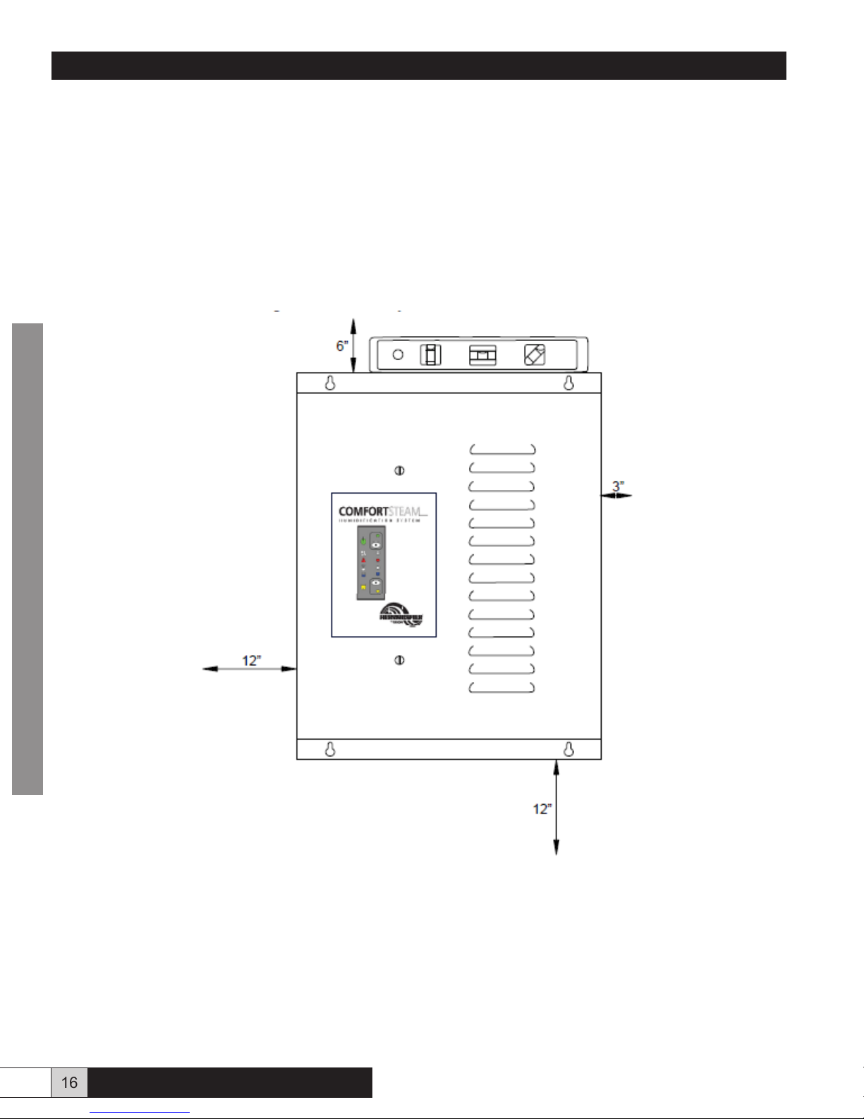
• The humidier must be installed on a vertical surface. Because of the length of the steam hose supplied, select the location of
the unit as close as possible within a maximum of 2 feet of the steam delivery tube/diffuser. Please see Fig. 14 for necessary
clearances around the humidier.
CONTRACTOR
REMINDER :
Figure 14
• Never install the humidier directly on the furnace body as this could void your furnace warranty.
16 www.trioniaq.com
Comfort
STEAM
TM
Page 17
Installation, Operation, & Maintenance Manual
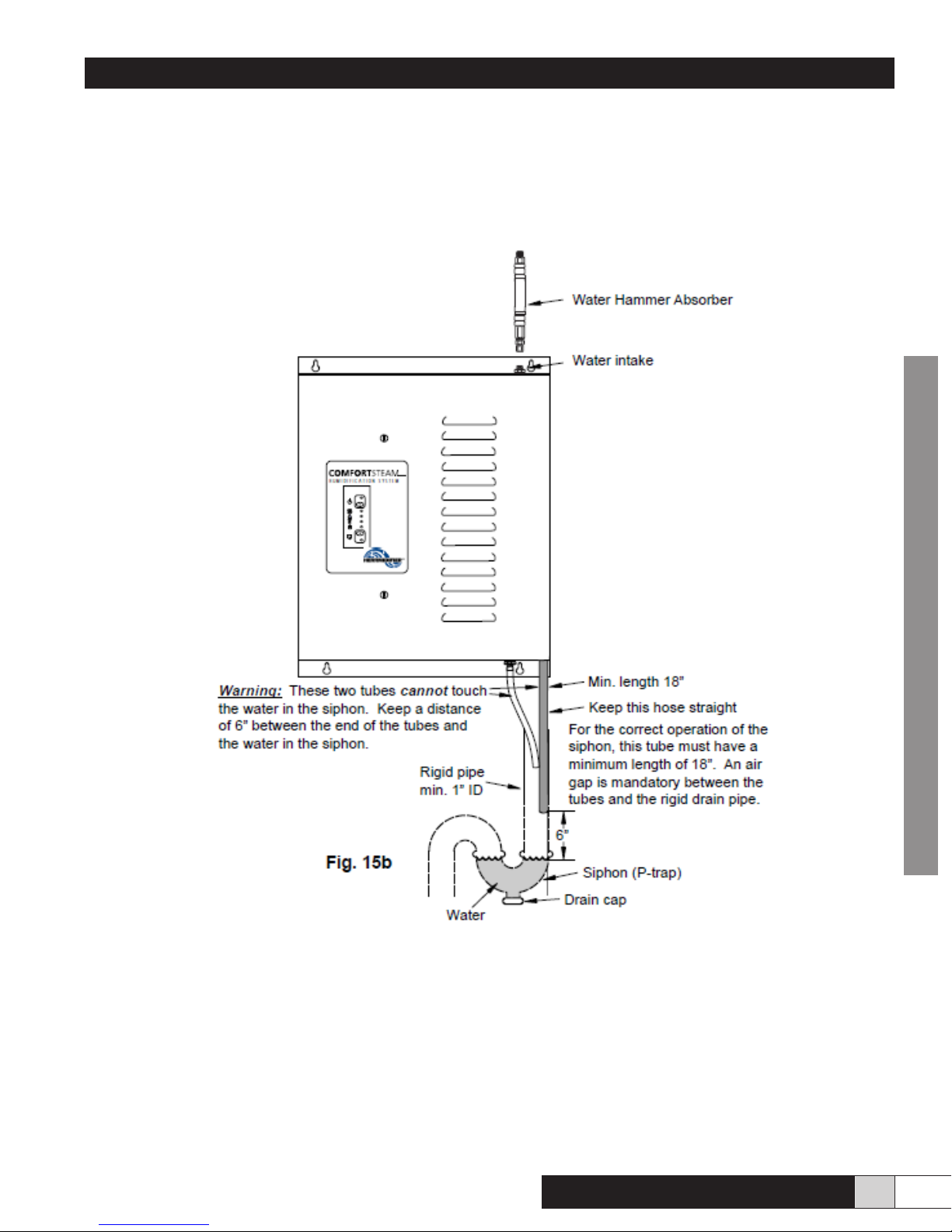
If a rigid drain pipe has to be installed under the unit and connected to the main house drain, we recommend a 1”
minimum I.D. tube or standard 1-1/2” I.D. ABS plumbing tube to do the installation. Please also install a siphon (P-trap) with a drain
cap.
The two exible drain tubes coming from the humidier which are inserted in the rigid pipe require a minimum free vertical length of
18”. It is very important to leave an air gap between the rigid pipe and the tubes to allow the siphon to function properly. The exible
tubes cannot touch the water contained in the siphon (Ptrap). Please see Fig. 15.
Figure 15
CONTRACTOR
• Since the unit is equipped with water level sensors, it is important to install it level from left to right and from back to front.
• Draw a level horizontal line on the wall and install two screws (# 8 minimum ) spaced at 11-5/8” from each other to hook the
humidier on the wall, then install two screws at the bottom of the unit and tighten them partially.
• Level the unit and tighten the four screws rmly.
Comfort
STEAM
TM
www.trioniaq.com
17
Page 18
Installation, Operation, & Maintenance Manual
17. Installing the water supply
Important Notes :
• Turn off the main water supply before beginning.
• The supply valve (not supplied) must be attached to a cold water pipe only, close to the humidier. Since the unit is draining hot
water, cold water is added to reduce the temperature before sending the water to the drain.
• We recommend installing a quarter of a turn shut off valve (not supplied) near the unit.
• In case of well water or other water containing particles, we also recommend installing a little strainer in the water line to protect
the solenoid valve.
• Model CFS-05B comes with the water supply line factory installed. The water hammer absorber mentioned below is not included.
Route water supply line as required.
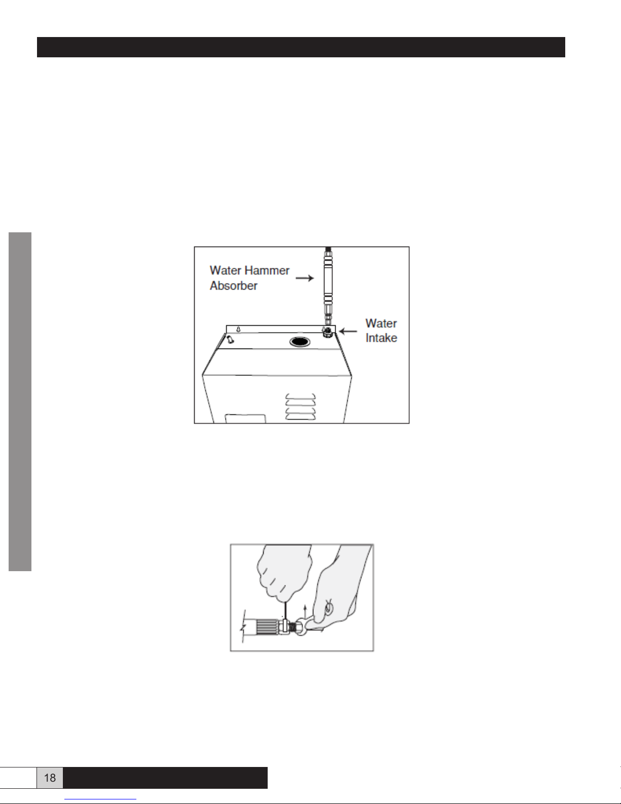
The water intake tting on the top of the humidier must be wrapped with teon tape. Screw the water hammer absorber (piece of
red rubber hose with two brass ttings) onto the water intake on the top of the humidier without stripping. Please see Fig. 16a. Also
use the same double wrench method for tightening.
CONTRACTOR
Figure 16a
At the other end of the water hammer absorber, connect the water supply tube, using the same type of tting used on the water supply
valve. Tighten the compression nut, without stripping, with two wrenches, one to hold the water hammer end, and one to turn the
compression nut. Please see Fig. 16b.
NOTE : The brass ferrule supplied is to be used only if the plastic supply tube is replaced by a copper tube. Either system works with
this humidier, but only plastic tubing is supplied.
Figure 16b
Keep the supply valve closed for now, you will open it during the start-up procedure.
18 www.trioniaq.com
Comfort
STEAM
TM
Page 19
Installation, Operation, & Maintenance Manual
18. Installing the air pressure probe
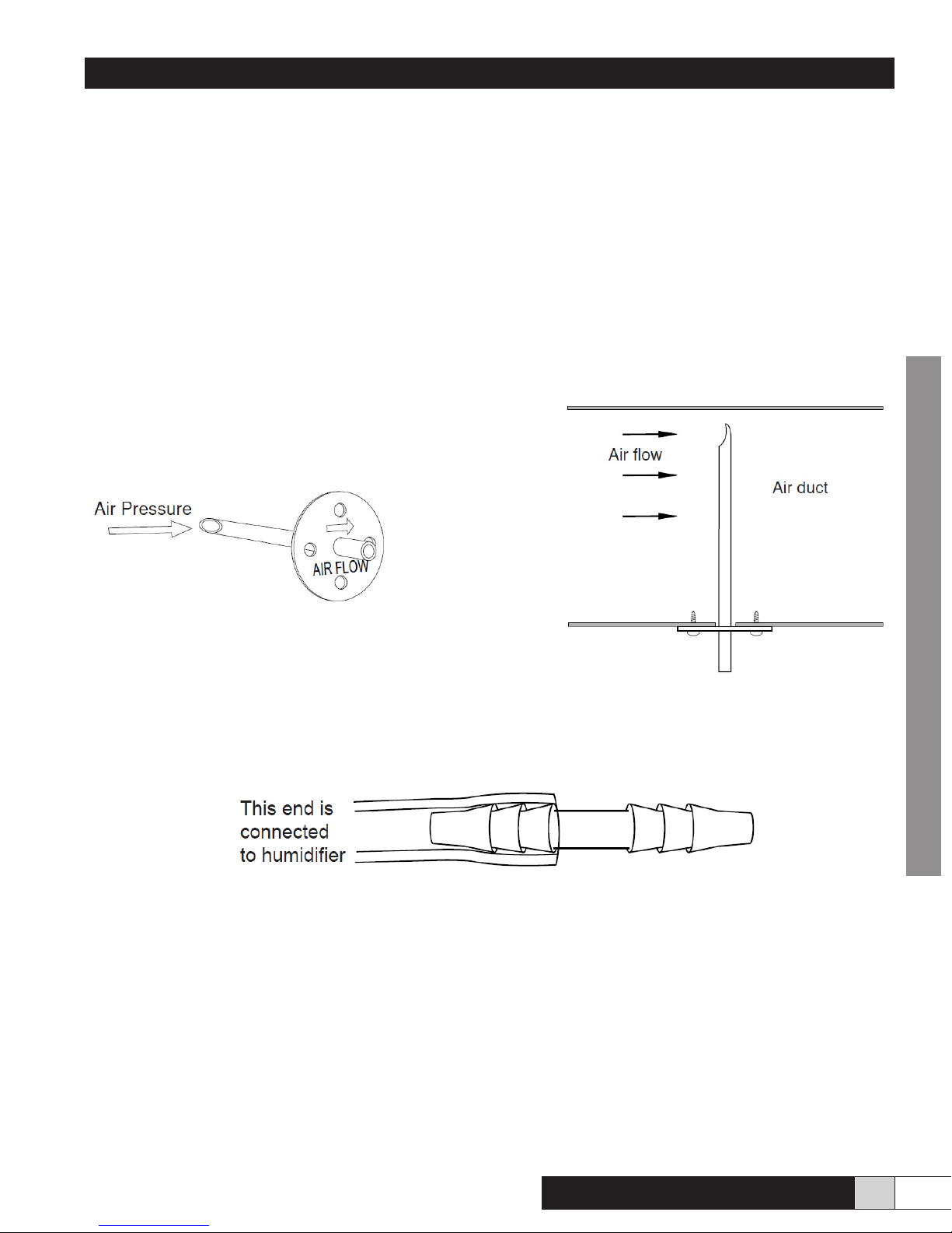
The pressure probe (also called a Pitot tube) connected to the pressure differential switch inside the unit checks whether there is
enough air pressure in the warm air duct to activate the humidier.
The probe has to be installed in the warm air duct, as close as possible to the humidier, but upstream (before the steam diffuser). A
48” long plastic tube is supplied to connect the pressure probe to the humidier.
Warning : Before installing anything on a duct, always check that you are not about to cut or drill into an air conditioning coil or
electrical accessories.
Drill a hole 3/8” dia. in an accessible location in the warm air duct.
Insert the probe and fasten it’s base to the duct using two sheet metal screws. The arrow visible on the probe ange indicates the air
ow direction in the duct (i.e. the curved end of the probe has to face the air ow). Please see Fig. 17a and Fig. 17b.
Figure 17a Figure 17a
Push one end of the plastic tube onto the probe outlet. Slip the other end of the tube onto the plastic barbed connector at the end of
the tubing already attached to the humidier. Please see Fig. 17c.
Figure 17c
CONTRACTOR
Comfort
STEAM
TM
www.trioniaq.com
19
Page 20
Installation, Operation, & Maintenance Manual
19. Making electrical connections
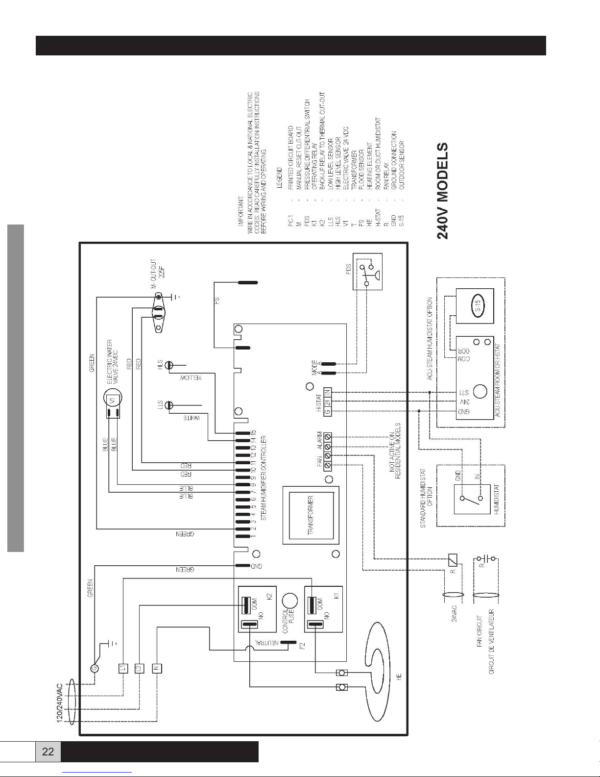
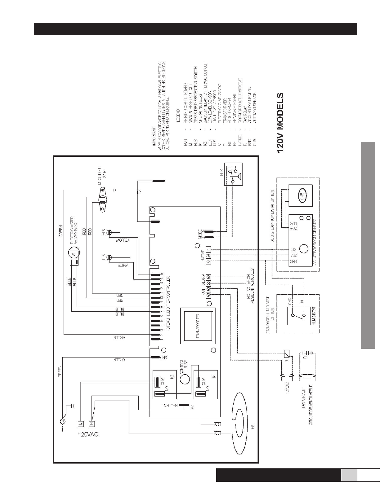
NOTE : All internal wiring is done at the factory. All external wiring shall be done by a qualied electrician and must conform to
procedures, regulations and local codes.
• A dedicated breaker in the main panel (or fused disconnect) must be installed.
• The voltage of the available power supply must be the same as the one required by the humidier.
• Except for the 120 volt model, all other humidiers need a 3-wire connection (L1-L2-Neutral) in order to supply 120 volts to the
transformer located on the control board.
• Ensure that the wire size and protection equipment conform to the sizes required by the Electrical
• Code.
• Wire according to the wiring diagram supplied in the cover of the unit.
• Starting the fan is mandatory with this type of humidier. The electronic controller board has a small relay that supplies a
dry contact at the terminals marked “FAN” to start the furnace fan. The installer must use this contact to engage a bigger relay
that starts the fan motor. Please refer to the furnace instruction manual to nd the right wiring diagram. The standard rating of
these contacts is 3A @ 240VAC or 6A @ 120VAC. Please do not exceed these ratings.
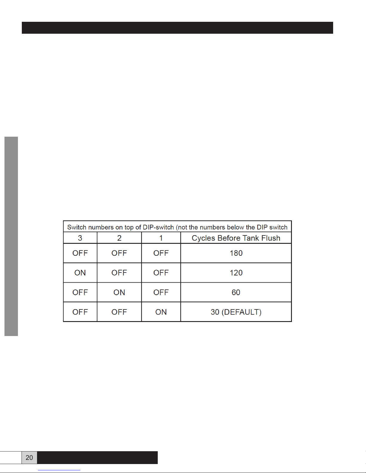
• Adjusting the DIP switches, located on the lower right corner of the circuit board, will change how the humidier handles
automatic tank ushes. The humidier will completely drain and rell with fresh water after a predetermined number of “rell
cycles”. Every time the unit replenishes the tank while producing steam is counted as one cycle. The table below shows how to
set the DIP switches in order to make the unit ush the tank at different intervals. Every 30 cycles equals approximately 5 hours
of operation.
NOTE : Cycles are cumulative across humidistat cycles. This means that if the humidistat satises when the counter is at 15 cycles,
the count will resume from 15 upon a new call for humidity. After the number of cycles, as set by the DIP switches, the tank will drain
and rell. If there is no call for humidity for 7 consecutive days, the tank will be drained and wait for future demand from the humidistat.
CONTRACTOR
20. Installing and connecting the humidistat
See wiring diagrams in section 21 for proper connection. If you are using a COMFORTSTEAM electronic humidistat with outdoor
sensor please refer to the instructions included with the humidistat. If you decide to use a standard mechanical humidistat, connect
the mechanical humidistat between the terminals marked GND (ground) & IN (input) on the humidier electronic board.
20 www.trioniaq.com
Comfort
STEAM
TM
Page 21
Installation, Operation, & Maintenance Manual
21. Start-up and test procedure
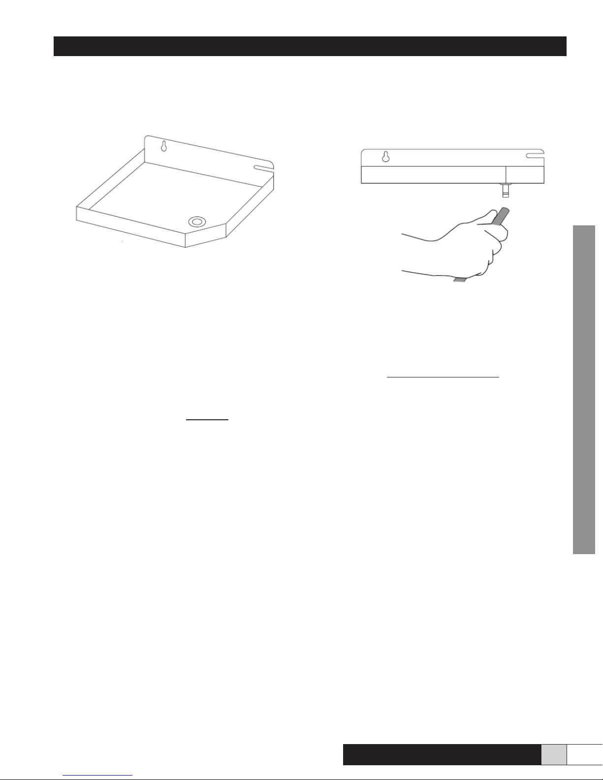
Take the 5/16 dia. plastic tube previously uncoiled and push one end on the connector located at the bottom of the overow pan.
Please see Fig. 18a and Fig.18b.
Figure 18a Figure 18b
• Install the overow pan under the tank by sliding it on its holding screws. You don’t have to tighten the screws.
• Reconnect the white wire for the overow sensor on the water pan.
• Cut the two drain tubes and insert them in the rigid pipe. Note that the main silicon drain tube must have a minimum length
of 18” below the bottom of the unit to allow the siphon to work properly. It is important to leave an air gap between the soft
tubes and the rigid pipe.
• Turn the handle of the water supply valve (fully counter-clockwise) to bring water to the humidier and let the water pressure
enter the system.
• Follow the water supply path completely and carefully check for leaks at the ttings.
• Turn the breaker “ON” to supply power to the humidier. The green light comes ON to conrm that the unit is ready to work.
• Test of the On/Standby button. Press the white button once. The green light goes OFF then ashes, indicating that the unit is in
standby mode but still powered. Press the white button again and keep it depressed for 3 seconds to power the humidier. The
green light will come ON, conrming that the unit is ready to work.
• Turn the humidistat clockwise past the middle of the scale to create a demand for humidity.
• The tank lls to the proper water level.
• The fan control starts the fan to move the air as the humidier starts boiling water and produces steam. If the fan cannot start,
the humidier suspends the ongoing operation. If the air pressure is insufcient, the unit will stop by itself. Please note that it
may take a few minutes to bring the water to a boil. The steam exits the water tank through the steam outlet and steam hose.
• The steam moves through the hose to the diffuser and is released into the warm air duct where it mixes with the moving air. 20.13
As water evaporates in the tank, the electric valve opens as needed to maintain the proper water level.
• When the humidity reaches the desired level the humidier stops producing steam. The unit may drain periodically in order to
eliminate the residues and keep the tank as clean as possible. The humidier also drains after a certain number of boiling – rell
cycles. If there is still a demand from the humidistat after draining, the tank rells and starts to produce steam again.
• When the humidistat is satised, the fan continues to run for a short period of time in order to eliminate the steam from the ducts.
• When everything is working ne, put the cover on the unit and attach it by turning the 1/4 turn latch to the right.
CONTRACTOR
Please don’t forget to leave this instruction manual with the customer.
Comfort
STEAM
TM
www.trioniaq.com
21
Page 22
Installation, Operation, & Maintenance Manual
22. Wiring diagrams
CONTRACTOR
22 www.trioniaq.com
Comfort
STEAM
TM
Page 23
Installation, Operation, & Maintenance Manual
CONTRACTOR
Comfort
STEAM
TM
www.trioniaq.com
23
Page 24
101 McNeill Rd. | Sanford, NC 27330
P: 800.884.0002 | F: 800.458.2379 | www.trioniaq.com | [email protected]
Trion
®
© Trion 2015. All Rights Reserved.Form No. 167649-001 Rev. 02/15
 Loading...