

Page 1
READ AND SAVE THESE INSTRUCTIONS
UNIT NOT FOR COMMERCIAL USE
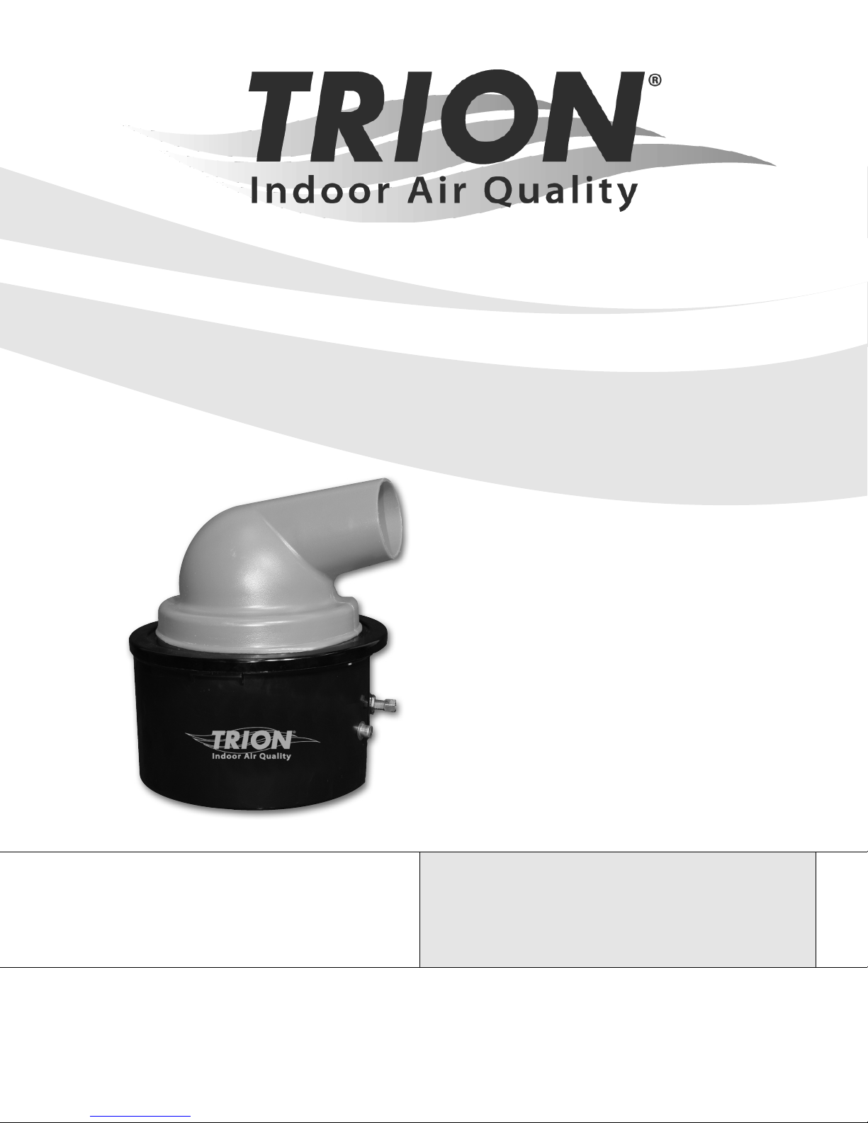
CB777
Centrifugal Atomizing Humidier
TRION® | www.trioniaq.com
Page 2

Installation, Operation, & Maintenance Manual
READ AND SAVE THESE INSTRUCTIONS
LIRE ET CONSERVER CES INSTRUCTIONS
TABLE OF CONTENTS
1. Warranty Statement .................................................................................................................................3
2. Safety Warnings .......................................................................................................................................3
3. Introduction ..............................................................................................................................................4
3.1. Unit Specications ............................................................................................................................. 4
3.2. Capacity Selection Guide .................................................................................................................. 4
3.3. Operation ........................................................................................................................................... 4
4. Installation ................................................................................................................................................ 5
4.1. Selecting the Unit Location ................................................................................................................ 5
4.2. Physical Installation ........................................................................................................................... 5
4.3. Final Installation .................................................................................................................................6
4.4. Electrical Installation .......................................................................................................................... 6
4.5. Humidistat Installation .......................................................................................................................7
5. Maintenance ............................................................................................................................................7
6. Parts List and Unit Diagram ..................................................................................................................... 8
2 www.trioniaq.com
ComfortBREEZE™ Model CB777
Page 3

Installation, Operation, & Maintenance Manual
CAUTION
Trion recommends that this humidier be installed by a
trained HVAC professional. Do not connect the unit to the
power source until the installation is complete. A thorough
checkout of the unit installation should be completed before
operating the unit. Failure to follow these directions may void
the manufacturer’s original warranty.
1. Warranty
This limited warranty covers TRION Residential Type Humidiers,
excluding duct work, wiring and installation. TRION warrants that all new
TRION humidiers are free from defects in material and workmanship
under normal, non-commercial use and service. TRION will remedy any
covered defects if they appear within 24 months from the date of original
installation & subject to the terms and conditions of this Limited 2-Year
Warranty stated below:
1. THIS LIMITED 2-YEAR WARRANTY is granted by TRION Customer
Service, 101 McNeill Road, Sanford, NC 27330.
2. This warranty shall extend only to any non-commercial owner who
has purchased the residential humidier other than for purposes of
resale.
3. All components are covered by this limited warranty except
expendable items, such as evaporative pads, media lter pads and
nozzles.
4. If, within the warranty period, any TRION residential humidier unit
or component requires service it must be performed by a competent
heating and/or air conditioning contractor (preferably the installing
contractor). TRION will not pay shipping charges, or labor charges
to remove or replace such defective parts or components. If the
part or component is found by inspection to contain such defective
material and workmanship it will be either repaired or exchanged free
of charge at TRION’s option, and returned freight collect.
5. In order to obtain the benets of this limited 2-year warranty, the owner
must notify the dealer or distributor of any defect within 30 days of its
discovery. If after reasonable time you have not received an adequate
response from the dealer or distributor, notify in writing to TRION
Customer Service 101 McNeill Road, Sanford, NC 27330, or call
1-800-884-0002 or email [email protected] Humidiers
which have been installed or become part of real estate cannot be
returned. TRION will receive, freight prepaid, only removable parts or
components of such defective humidiers.
6. This limited warranty does not apply to any part or component that is
damaged in transit or in handling, has been subject to misuse, neglect
or accident; has not been installed, operated and serviced according
to TRION’s instructions; has been operated beyond the factory rated
capacity; or altered in any such way that its performance is affected.
There is no warranty due to neglect, alteration or ordinary wear and
tear. TRION’s liability is limited to replacement of defective parts or
components and does not include the payment of the cost of labor
charges to remove or replace such defective components or parts.
7. TRION will not be responsible for loss of use of any product; loss of
time, inconvenience, or any other indirect, incidental or consequential
damages with respect to person or property, whether as a result
of breach of warranty, neglect or otherwise. SOME STATES DO
NOT ALLOW THE EXCLUSION OR LIMITATION OF INCIDENTAL
OR CONSEQUENTIAL DAMAGES, SO THE LIMITATION OR
EXCLUSION IN THE PRECEDING SENTENCE MAY NOT APPLY
TO YOU.
8. THIS WARRANTY GIVES YOU SPECIFIC RIGHTS, AND YOU MAY
ALSO HAVE OTHER RIGHTS WHICH VARY FROM STATE TO
STATE.
9. Any warranty by TRION of merchantability, tness for use or any other
warranty (express, implied or statutory), representation or guarantee
other than those set forth herein, shall expire at the expiration date
of this express limited warranty. SOME STATES DO NOT ALLOW
LIMITATIONS ON HOW LONG AN IMPLIED WARRANTY LASTS,
SO THE LIMITATION IN THE PRECEDING SENTENCE MAY NOT
APPLY TO YOU.
10. TRION reserves the right to make changes in the design and material
of its products without incurring any obligation to incorporate such
changes in units completed on the effective date of such change.
WARNING: Failure to install an air ow proving switch may result
in moisture build-up inside of the ductwork. Leaks, mold growth,
and severe water damage may result.
ComfortBREEZE™ Model CB777
Humidier 2-Year Limited Warranty
2. Safety & Warnings
DANGER
RISK OF ELECTRIC SHOCK
Before cleaning, servicing, or parts replacement, the unit must
be disconnected from all sources of electricity.
CAUTION
Read these instructions thoroughly before installing this unit.
Check data label and verify electrical specications agree
with those at the point of installation.
WARNING
Improper installation, adjustment, alteration, service, or
maintenance may cause property damage, injury, or death. This
appliance must be installed according to these instructions. Read
these instructions thoroughly before installing or servicing the unit.
WARNING
Failure to install this unit in a position that is level and plumb
may impair the unit’s ability to drain if an overow condition
presents itself. Damage to personal property may also result.
WARNING
Installation in freezing conditions can result in unit failure.
Damage to personal property may also result.
WARNING
This appliance is not intended for use by children or persons
with reduced physical, sensory or mental capabilities, or lack
of experience and knowledge, unless they have been given
supervision or instruction concerning use of the appliance
by a person responsible for their safety. Children should be
supervised to ensure that they do not play with the appliance.
WARNING
A drain pan should be installed under the unit and any supply
water / drain connections to prevent damage to property in the
event of a water leak or faulty operation.
CAUTION
TRION recommends that this humidier be installed by a
trained HVAC professional. Do not connect the unit to the
power source until the installation is complete. A thorough
checkout of the unit installation should be completed before
operating the unit. Failure to follow these directions may void
the manufacturer’s original warranty.
www.trioniaq.com
3
Page 4

Installation, Operation, & Maintenance Manual
3. Introduction
Congratulations on your choice of a TRION IAQ humidication
system. Your family can now look forward to breathing more
comfortable air, winter after winter. We are committed to
providing advanced products that improve the quality of the air
you breathe. The following information will familiarize you with
the operation of your new humidier and provide helpful tips on
how to obtain maximum performance from your unit.
The benets of a properly humidied environment (40-60%
Relative Humidity) are many. They include both personal comfort
as well as the preservation of furniture, draperies, carpets,
wooden oors and cabinets, paintings, pianos, etc.. Your home
will be more comfortable at a lower temperature (i.e.: 68° F)
at 40-60% Relative Humidity (RH) than at 71° to 72° F without
controlled humidity. Since every degree of temperature setback
represents about 3% of your heating costs, this can possibly
represent a signicant annual savings. During the heating
season, cold air is brought into the home and heated. When
heated, this air dries out and greatly increases its capacity to
hold more moisture. By using a humidier, a source of water
is provided to satisfy this increased moisture holding capability,
rather than having it drawn from our body surface and the
surrounding furnishings in the home. A properly maintained and
efciently operating humidier is a source of improved Indoor Air
Quality and personal comfort. We hope you will enjoy the
benets of your humidier.
3.1 Unit Specications
Type of Unit Centrifugal atomizing
Duct Mounting Return
GPD @ 140 ° F 6.0 maximum
GPD @ 120 ° F 6.0 maximum
GPD @ 100 ° F 6.0 maximum
Voltages 120V/ 240V
Unit Dimensions 10 1/2” DIA x 12 1/2” H
Standard Equipment Wall / duct mount humidistat
Features Centrifugal atomizer
Operates on low current, less than a
100w bulb
All brass valve assembly
Universal mounting options
2 year warranty
Installation Options:
Duct Side Mount
Free Standing Wall
Mounts on face of vertical or side of
horizontal return duct
Includes independent mounting
bracket
Mounts on wall
Includes independent mounting
bracket
3.2 Capacity Selection Guide
Sq Ft
Home
1000 .5 5.0 10.0
1500 3.0 10.0 16.5
2000 5.0 14.0 24.0
2500 7.5 19.0 30.5
3000 10.0 23.5 37.5
4000 14.5 33.0 51.5
*GPD = Gallons Per Day (Humidier Capacity)
The above calculations are for reference only and are based on
the following:
• Inside temperature 70°F / 50% relative humidity
• Outside Temp 20°F / 70% relative humidity
• 8 foot ceiling height
• Internal moisture gain of one pound per hour
• Furnace on-time of 70%
This chart uses A.R.I. standard designations:
A “Tight Home” is assumed to be well insulated with vapor
barriers, tight storm windows and doors, and a dampered
replace; air exchange rate of 0.50 changes per hour.
An “Average Home” is insulated and has a dampered replace,
but there are no vapor barriers, storm doors, or storm windows;
air exchange rate of 1.0 change per hour.
A “Loose Home” is generally one constructed before 1930, has
little or no insulation, no storm doors, storm windows, weather
stripping or vapor barriers, and often no effective dampering of
replaces; air exchange rate is as high as 1.5 changes per hour.
Tight Home
GPD*
Avg Home
GPD*
Loose Home
GPD*
3.3 Operation
Your centrifugal atomizer type humidier operates on the principle
of breaking down water droplets into a ne mist and atomizing
the moisture into the air. If applicable, set the humidistat in the
recommended range of 40-50% relative humidity for automatic
humidity control during the heating season (a lower setting
may be used to control condensation on single pane windows).
During the rst heating season, check the mineral buildup in the
humidier every month to establish the proper cleaning
schedule. Clean the unit at the end of each heating season, or
whenever mineral deposits appear to be impeding the discharge
of the water mist.
When shutting the humidier down for the summer months,
start with cleaning any mineral accumulation from the unit.
Leave the water turned off and the unit dry. If the furnace
fan is to be used for cooling purposes, disconnect power
to the humidier or turn the humidistat to the OFF position.
4 www.trioniaq.com
ComfortBREEZE™ Model CB777
Page 5
Installation, Operation, & Maintenance Manual
4. Installation
Selecting the Unit Location
Mounting on face of vertical return duct or side of horizontal
return duct When mounting your humidier on the face of
a horizontal return duct, or on the face of a vertical return
duct, certain conditions must be met for its proper operation:
• Mount the humidier on the vertical or horizontal cold air
return duct.
• Locate the humidier at least four (4) linear feet upstream of
either the furnace fan and/or lter and any turn in the duct.
This will ensure that condensation does not collect within
the duct and cause oxidation (rust).
• Mount the humidier at least six (6) linear feet (preferably
10 feet) upstream from any electronic air cleaner. Failure to
follow this recommendation can cause excessive nuisance
arcing and or power supply failure.
• If the duct seams inside the duct are not at, locate the
humidier at least three (3) linear feet upstream from the
seam.
• If the humidication needs of the home require more than
one humidier, each unit should be installed a minimum of
three (3) linear feet apart.
• DO NOT use this humidier on the discharge or warm air
supply side of a forced air heating system. This will reduce
the efciency of the humidier and may cause operational
problems.
• DO NOT mount the humidier in a furnace jacket.
• DO NOT install the humidier where freezing conditions
could occur.
• DO NOT install on gravity hot air systems.
Physical Installation
CAUTION
Only a trained HVAC servicer or contractor should install
this humidier. Do not connect the unit to the power source
until installation is complete. A thorough checkout of the unit
installation should be completed before operation. Failure to
follow these directions may void the manufacturer’s original
warranty.
Remember to select a location that is readily accessible for
periodic inspection and cleaning of your humidier. Allow a
minimum of 2” clearance in front of the humidier and 2” below
the water pan to allow for maintenance and repair.
2. Check the template with a level to ensure proper installation
of the Humidier.
3. Drill (4) 1/8” diameter holes (as shown on the template) for
mounting the wire bracket with sheet metal screws and at
washers provided.
4. Cut out the circle marked on the template. Do not cut this
opening over-sized.
5. With a hammer and heavy piece of metal, straighten the
metal edges to prevent injury to yourself and damage to the
Humidier.
6. Fit the rubber channel around the cut-out to cover the rough
edges of the hole and trim to t.
7. Attach the wire mounting bracket to the duct with (4) #10
sheet metal screws and at washers (provided).
8. Move the side adjusting arms vertically until the shelf of the
wire mounting bracket is level.
9. Mark the duct for securing adjusting arms and drill (2) 1/8”
holes. Fasten the arms in this position with (2) #10 sheet
metal screws and at washers (provided).
10. The oat and valve assembly have been factory adjusted
to maintain 1-1 1/2” of water in the water reservoir pan at
normal water pressure. If necessary, bend the oat arm to
the required position to maintain the water level at other
water pressures.
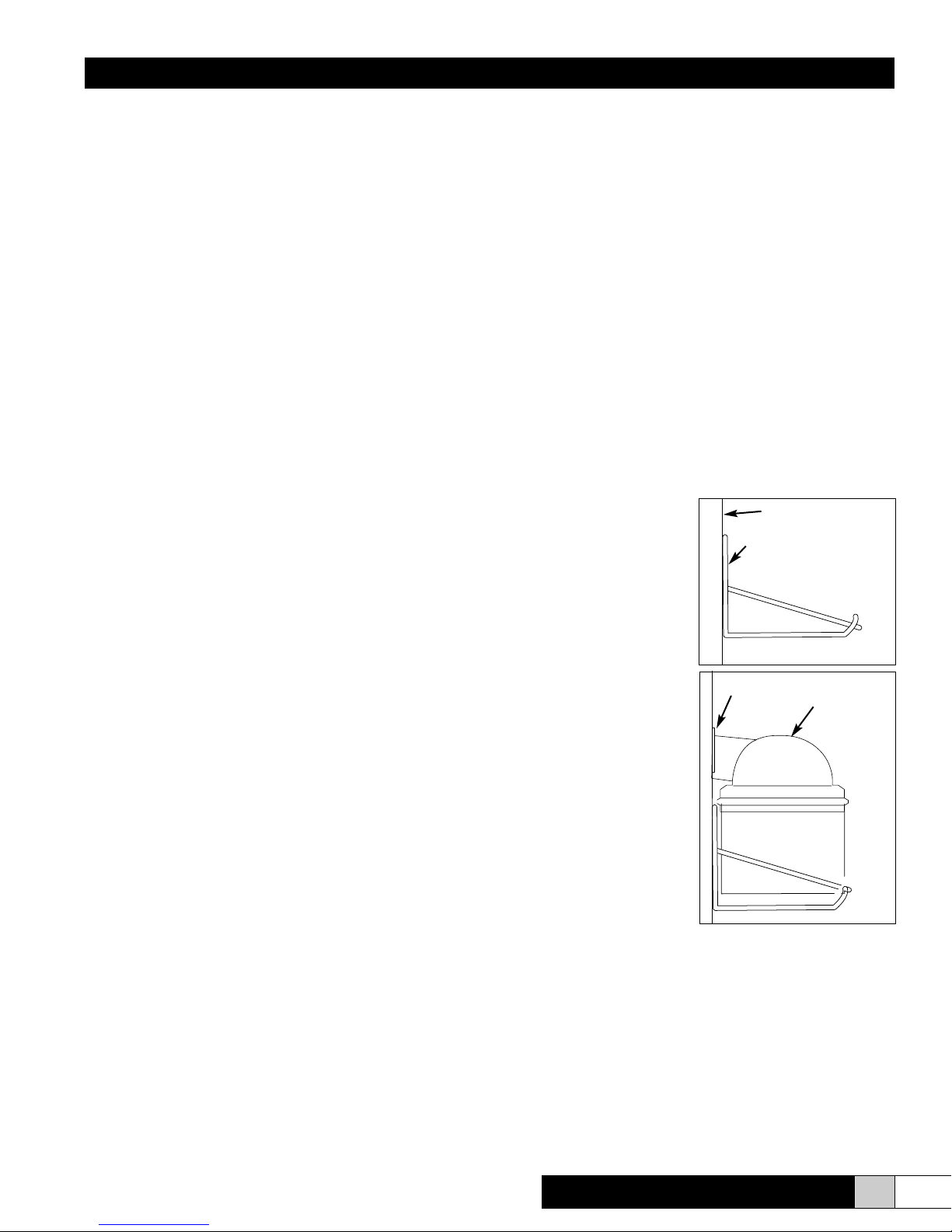
11. Before mounting the
humidier in its nal
position, carefully rotate the
impeller assembly by hand
to ensure it rotates freely.
Position the humidier on
the wire mounting bracket
with the oat and valve
assembly connection
facing the most convenient
location. Be sure that the
water reservoir pan feet
do not rest on the wire
bracket and that the water
reservoir pan is level.
12. The discharge dome
should approach the
opening in the duct,
however, it should not
extend into the duct. There
will be no heat loss, due
to the negative pressure
of the cold air return duct
(the air ow will create a
vacuum in the duct).
Cold air return duct
Wire mounting bracket
Bracket should be level
Rubber channel
Discharge
dome
Prior to installing this product:
• Read the instructions carefully to ensure safe operation.
Failure to follow them could damage the product or cause a
hazardous condition.
• Check the ratings given on the product to make sure it is
suitable for your application.
Mounting on the face of a vertical return duct or side of a
horizontal return
1. Mount the installation template on the side of the cold air
return air duct with the center line of the template lined up
with the center line of the return air duct. The narrow side of
the duct may be used if space permits.
ComfortBREEZE™ Model CB777
NOTE:
The following items are located in the carton:
• Bottom Pan
• Atomizing Assembly
• Discharge Dome
• Wire Mounting Bracket
The following items are located in the parts bag:
• Template
• (6) #10 x 3/4” screws
• (6) #10 at washers
• Rubber Channel
www.trioniaq.com
5
Page 6
Installation, Operation, & Maintenance Manual
Final installation steps for all mounting locations
• Install a saddle valve (not provided) on the nearest cold
water supply pipe (see the instructions on the package). If
applicable, connect the saddle valve upstream of any type
of water softener.
• After the saddle valve has been installed and 1/4” copper
tubing tted to the valve, but before attaching the copper
tubing to the oat and valve assembly, turn the saddle valve
to the open position and discharge the water into a bucket
or pan. This will allow the water to void the line of any debris
that may have accumulated during the installation process.
• Attach 1/4” copper tubing to the oat and valve assembly
with the ferrule and compression nut (provided).
Caution:
The oat and valve assembly must not turn when tightening the copper tubing compression ttings to the humidier
water reservoir pan tting.
• Turn the water supply on at the saddle valve.
• Check the water level in the water reservoir pan to ensure
it is 1 to 1 1/2” deep.
Failure to follow these instructions may result in improper
installation and therefore, void the manufacturer’s warranty.
1. Remove the cover from the junction box in the furnace
jacket.
2. Connect the humidier input leads to the two (2) leads that
run to the furnace blower motor. This connection provides
for the automatic operation of the humidier during the
heating season.
3. The humidier will only operate when the furnace blower is
in operation.
4. It is recommended to install the in the system to provide
optimum performance when continuous air circulation is
desired.
5. If a humidistat is not used in the installation, install an ON/
OFF switch in its place. This provides a simple, yet effective,
method of turning the humidier off during the summer
months when humidication is not desired.
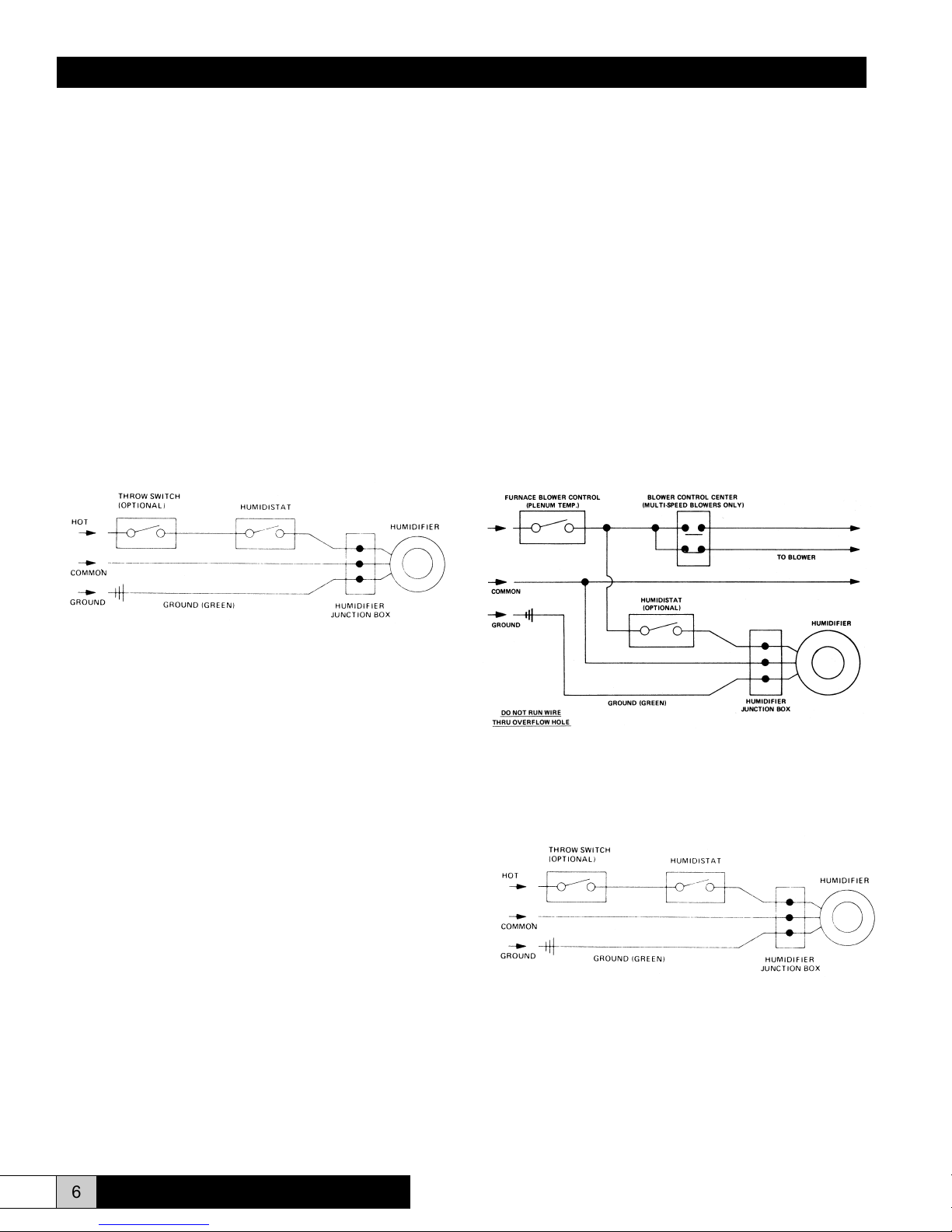
Wiring diagram for humidier installation - return duct
installation
Furnace wiring connection
TO BLOWER
=
INPUT POWER
IMPORTANT:
In installations where accidental overow could
cause water damage, connect a drain hose from the
humidier water reservoir pan overow tube to a
drain.
Do NOT use a soldered joint because the overow tube
will become heated and warp the water reservoir pan.
Electrical Installation
WARNING:
Improper electrical wiring can cause personal shock, injury,
or property damage. It is required that the unit be installed
by a properly qualied HVAC technician or electrician,
following NEC and any other local codes.
Electrical installation:
This humidier is intended to be wired directly to the integrated
control panel on your furnace. The electrical tap will provide
power to the humidier whenever the circulating air blower is
in operation.
INPUT POWER
Wiring diagram for humidier installation - free standing
installation
Dedicated wiring connection
INPUT POWER
Read the instructions in the furnace installation manual carefully
before attempting installation or operation of this humidier.
6 www.trioniaq.com
ComfortBREEZE™ Model CB777
Page 7

Installation, Operation, & Maintenance Manual
Humidistat Installation
Humidistat:
1. Locate the humidistat in the living area making sure that it
is at least ve (5) feet from a supply register (duct mounted
installation) or discharge nozzle (free standing installation).
2. The humidistat should be installed four and a half (4 1/2)
feet above the oor, out of the direct sun and not subject to
damage from trafc within the room.
3. If you would like the ability to cut off the electricity to the
humidier for maintenance, a throw -switch may be installed.
4. Turn the humidistat to the highest level (past 60%) and the
humidier should begin to run. The humidier should stop
when the humidistat is turned off.
5. Set the furnace controls and humidistat for the desired
conditions (30-40% RH is recommended). Operation of this
unit is automatic.
6. If condensation occurs on single pane windows, lower the
humidistat setting until the condensation has disappeared.
NOTE: It may take several days for the humidity level in
your home to reach comfortable levels.
5. Maintenance
Caution:
Before cleaning or servicing this unit, it is recommended
that the unit be disconnected from any electrical supply
outlet.
To enjoy the benets of a properly humidied environment,
periodic cleaning is necessary to control both water and
household impurities. Film or scum, which can contain bacteria
or fungi, may appear on the water surface, the sides, or bottom
of your humidier. A crusty deposit or scale may also appear
and is composed of minerals that have settled out of the water.
To improve the efciency of your humidier, and to reduce the
possibility of a health hazard, it is recommended that you take
the following precautions:
• Follow the manufacturer’s recommended cleaning and
maintenance instructions below and on the next page.
• The amount of minerals and other impurities in a water
source can vary greatly, therefore, the frequency of cleaning
the unit also varies.
• During the heating season, check for lm or scale build-up
in the unit, or any moving part. Establish a proper cleaning
schedule to ensure the efciency of the humidier.
• An algaecide, such as a humidier cleaning tablet or
bacteriostatic liquid/powder, can be used to combat algae
build-up, should it become evident.
• At the end of the winter humidication season, drain and
thoroughly clean your humidier as part of the summer
shutdown. Like your heating system and air conditioning
unit, periodic maintenance and cleaning are required to
ensure the safe and efcient operation of your humidier.
Due to the operation cycle of the furnace and humidier, it
may require 2 to 5 days to reach the proper humidication
level.
Your humidier is constructed from quality materials to assure
superior performance during normal operation. The motor
bearings are permanently lubricated and do not require oiling.
The motor is also thermal overload protected against extreme
conditions.
To clean the unit:
1. Turn the power to the furnace OFF or turn off the electric
switch to the humidier, if provided.
2. Disconnect the humidier motor leads.
3. Turn off the humidier water supply from the saddle valve
and remove water line from humidier.
4. Remove the humidier from the wire mounting bracket.
5. Remove the discharge dome from the humidier by pressing
on the sides of the dome and lifting upward.
6. Lift the entire atomizing assembly from the water reservoir
pan.
7. Remove the pump from the end of the impeller shaft. If the
pump is stuck in the motor drive shaft, run hot water over
the end of the shaft for a few seconds to loosen the pump.
8. Flush water through the impeller tube, ensuring that the six
holes at the top of the impeller tube are open and clear of
mineral deposits. A pipe cleaner works well for this cleaning
operation. Note: The impeller tube and pump can become
clogged by algae formations prevalent in certain water
sources. The addition of 10 drops of bleach to the water
reservoir pan each week is advisable.
9. Replace the pump into the impeller shaft.
10. Carefully rotate the impeller to ensure it turns freely. Do not
force the impeller shaft to turn or breakage could result.
11. With the atomizing assembly removed, clean the water
reservoir pan thoroughly. We suggest either a water/white
vinegar solution or liquid humidier cleaner.
12. Reassemble and remount the humidier by reversing steps
6, 5, and 4.
13. Reconnect the water line and motor leads to the humidier,
turn on the water supply from the saddle valve and restore
electrical power.
Maintenance instructions for models mounted on the face
of a vertical return duct, side of a horizontal return duct, or
mounted behind a wall using discharge extension.
ComfortBREEZE™ Model CB777
www.trioniaq.com
7
Page 8
Installation, Operation, & Maintenance Manual
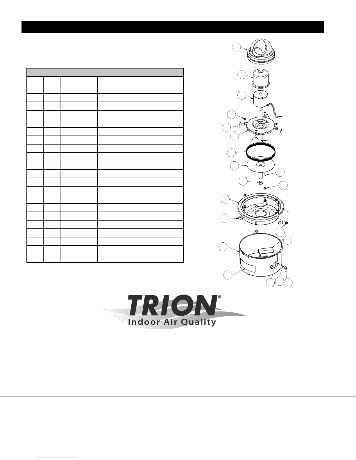
6. Parts List and Unit Diagram
1
Model 269450-001 Model CB777
Qty Item Part No Description
1 1 40 Discharge Dome
1 2 252413-001C Motor Cover
1 3 252596-001C Motor
6 4 10-32 Nut #10-32, Brass
4 5 19 Retainer Clip
1 6 352728-001C Motor Base
1 7 45C Diffuser Screen
1 8 D9PC Impeller
1 9 6-32 Set Screw #6-32 x 5/16
1 10 8AC Pump
4 11 90 Bushing
1 12 35PC Center Pan
4 13 23C Center Pan Support
1 14 16 Grommet
1 15 92PC Float & Valve Assembly
1 16 47-BC Bottom Pan
1 17 269529-001 Logo Label
1 18 FV-10 Locknut
1 19 FV-11 Sleeve, Brass, 1/4” Com. (Ferrule)
1 20 FV-12 Nut, Brass, 1/4” Com.
1 21 352680-002C Humidistat (Not Shown)
13
16
12
2
3
4
5
6
7
8
9
10
11
14
15
17
19
TRION
18
®
20
101 McNeill Rd. | Sanford, NC 27330
P: 800.884.0002 | F: 800.458.2379 | www.trioniaq.com | [email protected]
Form No. 269451-001 Rev. 07/17 © TRION 2017. All Rights Reserved.
 Loading...