

Trion 265000-001 Owner's Manual

Duct Mounted Atomizing Humidier
TM
Mister-
MINI
Table of Contents
Introduction ����������������������������������������������������������������������������������������������� 2
Specications ������������������������������������������������������������������������������������������� 2
Capacity Selection Chart �������������������������������������������������������������������������� 3
Output Capacity ���������������������������������������������������������������������������������������� 4
Installation
Location Selection ������������������������������������������������������������������������������ 5
Mounting �������������������������������������������������������������������������������������������� 6
Wiring �������������������������������������������������������������������������������������������7 & 8
Plumbing �������������������������������������������������������������������������������������������� 8
Start-up & Operation��������������������������������������������������������������������������������� 9
Maintenance
To Clean and Inspect ����������������������������������������������������������������������� 10
To Check for Leaks �������������������������������������������������������������������������� 10
To Clean Spray Nozzle �������������������������������������������������������������������� 11
To Clean Solenoid Valve ������������������������������������������������������������������ 12
Unit Diagram and Parts List�������������������������������������������������������������������� 13
Warranty ������������������������������������������������������������������������������������������������� 15
Caution: Read this manual carefully and completely
before installing this product. Installation and main-
tenance should be completed by qualied personnel.
265240-001 09/11
Introduction
The benets of a properly humidied environment (35-50% Relative Humidity) are
many� They include both personal comfort as well as the preservation of furniture,
draperies, carpets, wooden oors and cabinets, paintings, pianos, etc. Your home
can be more comfortable at a lower temperature (i.e.: 68° F) at 30-40% Relative
Humidity (RH) than at 71° to 72° F without controlled humidity. Since every degree
of temperature setback represents about 3% of your heating costs, this can possibly represent a signicant annual savings. During the heating season, cold air inltrates the home and must be heated. When heated, this air dries out and greatly
increases its capacity to hold more moisture. By using a humidier, a source of wa-
ter is provided to satisfy this increased moisture holding capability, rather than having it drawn from our body surface and the surrounding furnishings in the home�
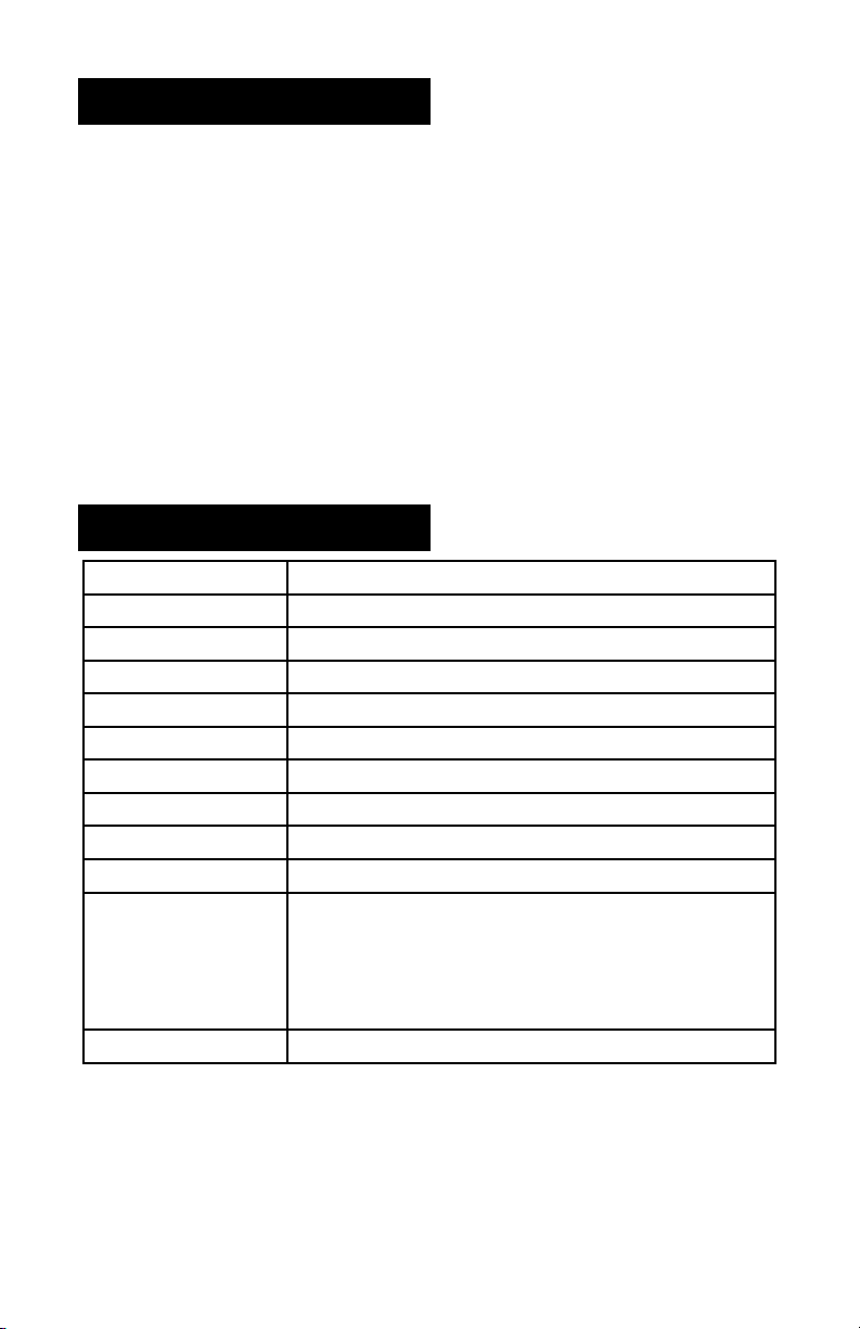
Specications
Model Mister-MINI
Type of Unit Atomizing/Evaporative
Duct Position Supply Duct
GPD @ 140°F 12�5 Gallons per day @ 60 psi
GPD @ 120°F 12�5 Gallons per day @ 60 psi
GPD @ 100°F Not Recommended for Temperatures <120°F
Voltage 24 VAC
Unit Dimensions 4�25"W x 3�88" D x 4�25" H
Duct Opening 3�125" W x 3�125" H
Shipping Weight 3 lbs
What's in the box (1) Humidier
(1) Wall/Duct Mount Humidistat
10' Plastic Water Line
(1) Instruction Manual
(1) Mounting Template
Features Two Year Warranty
2
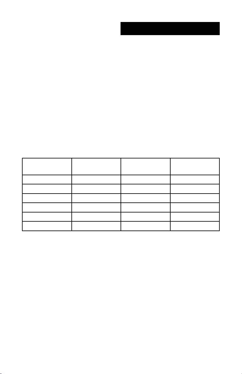
Capacity Selection
The table below is for reference only and is based upon the following:
Inside temperature of 70°F / 35% relative humidity
Outside temperature of 20°F / 70% relative humidity
8 foot ceiling height
Internal moisture gain of one pound per hour
Furnace on-time 70%
The chart uses Standard ASHRAE denitions:
A “Tight Home” is assumed to be well insulated with vapor barriers, tight storm
windows and doors, and a dampered replace. Air exchange rate of .5 changes
per hour�
An “Average Home” is insulated and has a dampered re place, but there are
no vapor barriers, storm doors, or storm windows� Air exchange rate of 1�0
changes per hour�
A “Loose Home” is generally one constructed before 1930, has little or no insulation, no storm doors, storm windows, weather stripping or vapor barriers,
and often no effective dampering of replaces. Air exchange rate is as high as
1�5 changes per hour
Sq. Footage of
Home
Tight Home
(GPD)
Average Home
(GPD)
1000 0�5 5�0 10�0
1500 3�0 10�0 16�5
2000 5�0 14�0 24�0
2500 7�5 19�0 30�5
3000 10�0 23�5 37�5
4000 14�5 33�0 51�5
Loose Home
(GPD)
3
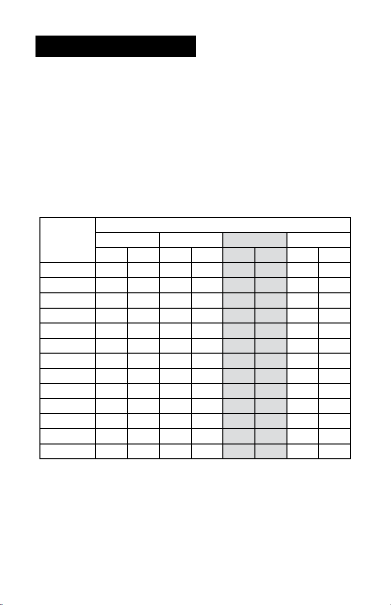
Output Capacity
Increasing or decreasing the nozzle size or supply water pressure can vary the
output capacity of this humidier. It is recommended that the humidier NOT be
used with water pressures below 40 PSI, otherwise, the mist may be adversely
affected�
This humidier comes standard with a .75 GPH (oil) nozzle with a hollow spray pattern� Alternatively sized nozzles may be purchased from your local HVAC supply
house or plumbing supply outlet. If the water pressure uctuates or is excessive,
a pressure regulator should be installed in the water line supplying the humidier.
The following chart illustrates the capacity of different nozzles at varying water
pressures� The capacity listed on the nozzle is for #2 fuel oil at 100 psi and should
not be considered relative to the water capacity of this humidier.
Nozzle
Pressure
(PSI)
0�4 0�5 0�75 1
GPH GPD GPH GPD GPH GPD GPH GPD
Nozzle Size
40 0�23 5�5 0�28 6�8 0�43 10�2 0�57 13�7
45 0�24 5�8 0�30 7�2 0�45 10�9 0�60 14�5
50 0�25 6�1 0�32 7�6 0�48 11�5 0�64 15�3
55 0�27 6�4 0�33 8�0 0�50 12�0 0�67 16�0
60 0�28 6�7 0�35 8�4 0�52 12�5 0�70 16�7
65 0�29 7�0 0�36 8�7 0�54 13�1 0�73 17�4
70 0�30 7�2 0�38 9�0 0�56 13�6 0�75 18�1
75 0�31 7�5 0�39 9�4 0�58 14�0 0�78 18�7
80 0�32 7�7 0�40 9�7 0�60 14�5 0�80 19�3
85 0�33 8�0 0�41 10�0 0�62 14�9 0�83 19�9
90 0�34 8�2 0�43 10�2 0�64 15�4 0�85 20�5
95 0�35 8�4 0�44 10�5 0�66 15�8 0�88 21�1
100 0�36 8�6 0�45 10�8 0�68 16�2 0�90 21�6
NOTE: Due to the operation cycle of the furnace and humidier,
it may take from 2-5 days to reach the proper humidication level.
4
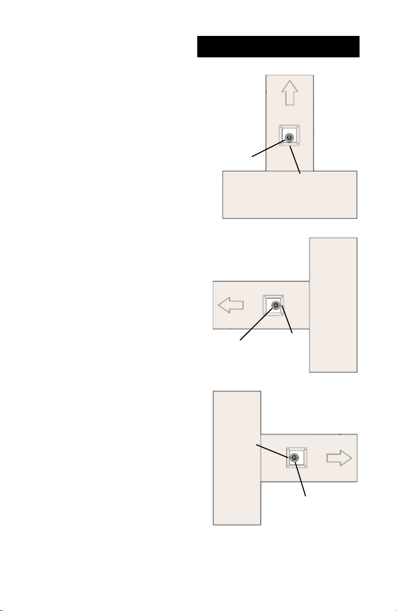
When selecting a location for the installa-
tion of your humidier, certain conditions
must be met for its proper operation� The
recommended location for this humidier
is on the warm air supply plenum, approximately 3 inches downstream of the
furnace discharge� The air temperature
must be at least 120ºF in order for the
temperature switch to operate properly�
In narrow plenum/duct arrangements,
the humidier should be mounted on the
narrow side of the duct� Select a location so that the spray from the nozzle will
not impinge on the furnace fan, control
switches, air conditioning or heat coils, or
walls of the duct�
The humidier should be mounted so
that the furnace air carries the mist away
from the humidier temperature switch.
The direction of airow is indicated inside
of the humidier housing and on the rating label on the side of the humidier.
DO NOT install the humidier where
freezing conditions could occur or where
accidental overow could cause water
damage to the home or property�
DO NOT install the humidier where the
temperature will exceed 180°F. Exces-
sive heat may cause softening and distortion of the plastic housing�The instal-
lation of a water lter may reduce the
potential clogging of the nozzle and solenoid valve in hard water applications�
Installation
Supply Plenum
Nozzle
Supply Plenum
Nozzle
Temperature
Switch
Temperature
Temperature
Switch
Furnace
Switch
Furnace
Supply Plenum
Nozzle
Furnace
5
 Loading...